EP3217116A1 - Rückgewinnung von durch einen verdichterantrieb erzeugter wärme - Google Patents
Rückgewinnung von durch einen verdichterantrieb erzeugter wärme Download PDFInfo
- Publication number
- EP3217116A1 EP3217116A1 EP16159292.8A EP16159292A EP3217116A1 EP 3217116 A1 EP3217116 A1 EP 3217116A1 EP 16159292 A EP16159292 A EP 16159292A EP 3217116 A1 EP3217116 A1 EP 3217116A1
- Authority
- EP
- European Patent Office
- Prior art keywords
- refrigerant
- compressor
- heat exchanger
- heat
- evaporator
- Prior art date
- Legal status (The legal status is an assumption and is not a legal conclusion. Google has not performed a legal analysis and makes no representation as to the accuracy of the status listed.)
- Withdrawn
Links
Images

Classifications
-
- F—MECHANICAL ENGINEERING; LIGHTING; HEATING; WEAPONS; BLASTING
- F25—REFRIGERATION OR COOLING; COMBINED HEATING AND REFRIGERATION SYSTEMS; HEAT PUMP SYSTEMS; MANUFACTURE OR STORAGE OF ICE; LIQUEFACTION SOLIDIFICATION OF GASES
- F25B—REFRIGERATION MACHINES, PLANTS OR SYSTEMS; COMBINED HEATING AND REFRIGERATION SYSTEMS; HEAT PUMP SYSTEMS
- F25B5/00—Compression machines, plants or systems, with several evaporator circuits, e.g. for varying refrigerating capacity
- F25B5/04—Compression machines, plants or systems, with several evaporator circuits, e.g. for varying refrigerating capacity arranged in series
-
- F—MECHANICAL ENGINEERING; LIGHTING; HEATING; WEAPONS; BLASTING
- F25—REFRIGERATION OR COOLING; COMBINED HEATING AND REFRIGERATION SYSTEMS; HEAT PUMP SYSTEMS; MANUFACTURE OR STORAGE OF ICE; LIQUEFACTION SOLIDIFICATION OF GASES
- F25B—REFRIGERATION MACHINES, PLANTS OR SYSTEMS; COMBINED HEATING AND REFRIGERATION SYSTEMS; HEAT PUMP SYSTEMS
- F25B31/00—Compressor arrangements
- F25B31/006—Cooling of compressor or motor
-
- F—MECHANICAL ENGINEERING; LIGHTING; HEATING; WEAPONS; BLASTING
- F25—REFRIGERATION OR COOLING; COMBINED HEATING AND REFRIGERATION SYSTEMS; HEAT PUMP SYSTEMS; MANUFACTURE OR STORAGE OF ICE; LIQUEFACTION SOLIDIFICATION OF GASES
- F25B—REFRIGERATION MACHINES, PLANTS OR SYSTEMS; COMBINED HEATING AND REFRIGERATION SYSTEMS; HEAT PUMP SYSTEMS
- F25B40/00—Subcoolers, desuperheaters or superheaters
- F25B40/06—Superheaters
-
- F—MECHANICAL ENGINEERING; LIGHTING; HEATING; WEAPONS; BLASTING
- F25—REFRIGERATION OR COOLING; COMBINED HEATING AND REFRIGERATION SYSTEMS; HEAT PUMP SYSTEMS; MANUFACTURE OR STORAGE OF ICE; LIQUEFACTION SOLIDIFICATION OF GASES
- F25B—REFRIGERATION MACHINES, PLANTS OR SYSTEMS; COMBINED HEATING AND REFRIGERATION SYSTEMS; HEAT PUMP SYSTEMS
- F25B2339/00—Details of evaporators; Details of condensers
- F25B2339/04—Details of condensers
- F25B2339/047—Water-cooled condensers
-
- F—MECHANICAL ENGINEERING; LIGHTING; HEATING; WEAPONS; BLASTING
- F25—REFRIGERATION OR COOLING; COMBINED HEATING AND REFRIGERATION SYSTEMS; HEAT PUMP SYSTEMS; MANUFACTURE OR STORAGE OF ICE; LIQUEFACTION SOLIDIFICATION OF GASES
- F25B—REFRIGERATION MACHINES, PLANTS OR SYSTEMS; COMBINED HEATING AND REFRIGERATION SYSTEMS; HEAT PUMP SYSTEMS
- F25B2400/00—General features or devices for refrigeration machines, plants or systems, combined heating and refrigeration systems or heat-pump systems, i.e. not limited to a particular subgroup of F25B
- F25B2400/05—Compression system with heat exchange between particular parts of the system
- F25B2400/054—Compression system with heat exchange between particular parts of the system between the suction tube of the compressor and another part of the cycle
-
- F—MECHANICAL ENGINEERING; LIGHTING; HEATING; WEAPONS; BLASTING
- F25—REFRIGERATION OR COOLING; COMBINED HEATING AND REFRIGERATION SYSTEMS; HEAT PUMP SYSTEMS; MANUFACTURE OR STORAGE OF ICE; LIQUEFACTION SOLIDIFICATION OF GASES
- F25B—REFRIGERATION MACHINES, PLANTS OR SYSTEMS; COMBINED HEATING AND REFRIGERATION SYSTEMS; HEAT PUMP SYSTEMS
- F25B2500/00—Problems to be solved
- F25B2500/28—Means for preventing liquid refrigerant entering into the compressor
Definitions
- the present invention relates to a heat pump system, and more particularly to a heat pump system that can recover heat generated by a compressor driver in its operation.
- a basic heat pump system typically has a refrigerant circuit including a compressor, a condenser, an expansion valve, and an evaporator. These components are generally serially connected via conduits or piping.
- the compressor generally compresses a refrigerant from a low pressure gas state to a high pressure gas state.
- the gas refrigerant leaves from the compressor and then flows through the condenser for being condensed at a substantially constant pressure to a saturated liquid state.
- the expansion valve is used to control the amount of refrigerant entering into the evaporator.
- the liquid refrigerant from the condenser flows through the expansion valve, results in the pressure of the liquid is decreased.
- the evaporator then evaporates the refrigerant to change its state from liquid to gas by absorbing heat from a secondary flow, such as an air flow passing through the evaporator.
- the refrigerant discharged from the evaporator goes back to the compressor to repeat the cycle.
- the evaporation of the refrigerant is finished in the evaporator, and the refrigerant sucked into the compressor should be complete gas state.
- the refrigerant sucked into the compressor from the evaporator may not be changed into the super-heated vapor that has evaporated beyond the saturated state. As a result, noise is increased and performance of the compressor is deteriorated.
- the compressor generally compresses or expands the refrigerant by using a piston connected to a motor.
- a compressor driver is connected between the mains supply and the compressor, and is also connected with a control board of the heat pump system.
- the compressor driver receives the control commands and the speed set-point from the control board, and then converts the power with the normal shape of the mains supply into a waveform that is suitable for powering the motor of the compressor to achieve a required speed set-point.
- the compressor driver generally includes a casing, and a lot of electronic components and specific circuits contained therein, such as MCU, IGBT(Insulated Gate Bipolar Transistor) modules, EMC filters, and PFC (Power Factor Correction) circuits. These electronic parts generate heat during the driver operation.
- the driver is usually equipped with a heat sink, like fins attached to the casing to dissipate heat with forced air flow, in the period, the heat sink may reach a temperature of 90 ⁇ to 125 ⁇ during the driver operation.
- the heat generated by the compressor driver is dissipated into the ambient air without recycling.
- a heat pump system including a refrigerant circuit, a compressor driver and an additional heat exchanger.
- the refrigerant circuit includes a compressor for compressing a refrigerant, a condenser downstream of the compressor for cooling the refrigerant, a throttling device downstream of the condenser for lowering the pressure of the refrigerant, and an evaporator downstream of the throttling device for vaporizing the refrigerant.
- the compressor driver is electrically connected with the compressor for powering the compressor, and the compressor driver generates heat in operation.
- the additional heat exchanger is connected with the compressor driver to obtain the heat generated by the compressor driver, and the additional heat exchanger is placed in the refrigerant circuit for transferring the obtained heat to the refrigerant passing therethrough.
- the additional heat exchanger performs like an additional evaporator to increase the evaporation capacity. Even if the liquid refrigerant could not be phase changed into a complete gas state in the evaporator, the additional heat exchanger can further heat the refrigerant to change its state into the super-heated vapor that has evaporated beyond the saturated state. Therefore, the possibility of liquid refrigerant entering the compressor can be reduced, and performance and efficiency of the system can be improved accordingly.
- the additional heat exchanger transfers the obtained heat to the refrigerant after the refrigerant flowing through the evaporator.
- the additional heat exchanger is placed at an inlet of the compressor.
- the additional heat exchanger transfers the obtained heat to the refrigerant before the refrigerant flowing through the evaporator.
- the additional heat exchanger is disposed at an inlet of the evaporator.
- the additional heat exchanger is connected with the compressor driver via fluid pipes, and a working medium flows in the fluid pipes to transfer the heat from the compressor driver to the additional heat exchanger.
- the working medium is in liquid form.
- the refrigerant circuit has a first heat exchanger operating as the condenser in a heating mode and operating as the evaporator in a cooling mode, and a second heat exchanger operating as the evaporator in the heating mode and operating as the condenser in the cooling mode.
- a heat pump system can be used for heating building interiors.
- the heat pump system includes a refrigerant circuit R and a superheating circuit SH.
- the refrigerant circuit R typically includes a compressor 10, a first heat exchanger 20 operating as a condenser, a throttling device 30, and a second heat exchanger 40 operating as an evaporator.
- the compressor 10 generally uses electrical power to compress a refrigerant from a low pressure gas state to a high pressure gas state thereby increasing the temperature, enthalpy and pressure of the refrigerant.
- the first heat exchanger 20 can be a plate-type heat exchanger.
- the refrigerant leaving from the compressor 10 flows through the first heat exchanger 20 for being condensed at a substantially constant pressure to a saturated liquid state.
- a heat transfer medium such as water passing through the first heat exchanger 20 obtains heat from the refrigerant flow and flows through a space heating/cooling circuit 60 to dissipate heat into building interiors.
- the space heating/cooling circuit 60 can be placed within a building (now shown) and allows hot or cold water acting as the heat transfer medium to pass therethrough for heating or cooling the building interiors.
- the throttling device 30 can take form of an electronic expansion valve for being used to control the amount of the refrigerant entering into the second heat exchanger 40.
- the liquid refrigerant from the first heat exchanger 20 flows through the electronic expansion valve 30, result in the pressure of the liquid is decreased.
- the refrigerant evaporates partially causing the refrigerant to change to a mixed liquid-gas state, reducing its temperature down to a value that makes possible heat exchanges in the second heat exchanger 40.
- the second heat exchanger 40 is a heat exchanger where the heat energy available in a working medium, like air flow is transferred to the refrigerant flow that evaporates inside from liquid to gas.
- the gas refrigerant discharged from the second heat exchanger 40 is sucked into the compressor 10 and repeats the refrigerant cycle for heating purpose.
- An additional heat exchanger 50 that can take form of a plate-type heat exchanger is connected in the refrigerant circuit R. Along the flowing direction of the refrigerant, the additional heat exchanger 50 is placed after the second heat exchanger 40 that is acting as the evaporator, and preferably at an inlet of the compressor 10.
- a compressor driver 11 is electrically connected with the compressor 10 to convert the power with the normal shape of the mains supply into a waveform that is suitable for powering a motor of the compressor to achieve a required speed set-point.
- the compressor driver 11 includes a casing, and a lot of electronic components and specific circuits contained in the casing, such as MCU, IGBT(Insulated Gate Bipolar Transistor) modules, EMC filters, and PFC (Power Factor Correction) circuits. These electronic parts generate heat during the driver operation, and in order to avoid thermal overload, the driver can be equipped with a heat sink, like fins attached to the casing to dissipate heat with forced air flow.
- the additional heat exchanger 50 is connected with the compressor driver 11 via fluid pipes to form the super-heating circuit SH.
- the fluid pipes can be made from appropriate metallic material, like aluminum, copper, or alloy containing aluminum or copper. Part of the fluid pipes encircles the casing of the compressor driver 11 or attached the heat sink so that the heat generated by the compressor driver 11 can be absorbed by a working medium flowing in the fluid pipes.
- the working medium can be in liquid form, like water.
- the working medium can also be in gaseous state, and in this embodiment, the forced air flow passing through the heat sink for absorbing heat generated by the compressor driver 11 can be collected and guided into the fluid pipes to act as the working medium.
- the working medium is pumped to circulate in the super-heating circuit SH.
- the working medium obtains heat when it passes through the compressor driver 11, and transfers the obtained heat to the refrigerant when it passes through the additional heat exchanger 50.
- the additional heat exchanger 50 performs like an additional evaporator to increase the evaporation capacity, by this means, even if the liquid refrigerant could not be phase changed into a complete gas state in the second heat exchanger 40, the additional heat exchanger 50 can further heat the refrigerant to change its state into the super-heated vapor that has evaporated beyond the saturated state. Therefore, the possibility of liquid refrigerant entering the compressor can be reduced, and performance and efficiency of the system can be improved accordingly.
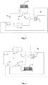
- Fig. 2 shows a second embodiment that the heat pump system works for cooling interiors of buildings.
- the refrigerant cycle is inversed for cooling purpose.
- the first heat exchanger 20 operates as the evaporator
- the second heat exchanger 40 operates as the condenser.
- the heat transfer medium like water dissipates heat to the refrigerant for vaporizing the refrigerant, and the water becoming cold passes through the space heating/cooling circuit 60 for cooling the building interiors.
- the additional heat exchanger 50 is placed after the first heat exchanger 20 acting as the evaporator now, preferably at the inlet of the compressor 10.
- Fig. 3 shows a third embodiment that the heat pump system works for heating purpose. Compared with the first embodiment, the only difference is the place of the additional heat exchanger.
- the additional heat exchanger 50 is placed before the second heat exchanger 40 that is acting as the evaporator now, preferably at an inlet of the second heat exchanger 40. In this way, the temperature of the refrigerant is increased before the refrigerant entering into the evaporator, and more energy are used to change the refrigerant phase from liquid form into gaseous state, thereby reducing the possibility of liquid refrigerant entering the compressor 10.
- Fig. 4 shows a fourth embodiment that the heat pump system works for cooling purpose.
- the additional heat exchanger 50 is placed before the first heat exchanger 20 that is acting as the evaporator now, preferably at the inlet of the first heat exchanger 20. In this way, the temperature of the refrigerant is increased before the refrigerant entering into the evaporator, and more energy are used to change the refrigerant phase from liquid form into gaseous state, thereby reducing the possibility of liquid refrigerant entering the compressor 10.
- the refrigerant circuit R can further include a reversing valve, like a four-way valve for switching the refrigerant cycle between a heating mode and a cooling mode.
- the first heat exchanger 20 operates as the condenser in the heating mode and operating as the evaporator in the cooling mode
- the second heat exchanger 40 operates as the evaporator in the heating mode and operates as the condenser in the cooling mode.
- Two additional heat exchangers 50 can be placed in the refrigerant circuit R, and be selectively energized in the heating mode and the cooling mode respectively to increase the evaporation capacity of the system.
- one additional heat exchanger can be placed after the second heat exchanger 40 (as shown in Fig. 1 ) or before the second heat exchanger 40 (as shown in Fig. 3 ) for being energized in the heating mode
- the other additional heat exchanger can be placed after the first heat exchanger 20 (as shown in Fig. 2 ) or before the first heat exchanger 20 (as shown in Fig. 4 ) for being energized in the cooling mode.
- a three-way valve (not shown) can be provided and connected with the two additional heat exchangers to energize appropriate one of them in the heating or cooling mode to increase the evaporation capacity with additional energy obtained from the compressor driver 11, thereby reducing the possibility of liquid refrigerant entering the compressor 10.
Landscapes
- Engineering & Computer Science (AREA)
- Physics & Mathematics (AREA)
- Mechanical Engineering (AREA)
- Thermal Sciences (AREA)
- General Engineering & Computer Science (AREA)
- Compression-Type Refrigeration Machines With Reversible Cycles (AREA)
Priority Applications (1)
| Application Number | Priority Date | Filing Date | Title |
|---|---|---|---|
| EP16159292.8A EP3217116A1 (de) | 2016-03-09 | 2016-03-09 | Rückgewinnung von durch einen verdichterantrieb erzeugter wärme |
Applications Claiming Priority (1)
| Application Number | Priority Date | Filing Date | Title |
|---|---|---|---|
| EP16159292.8A EP3217116A1 (de) | 2016-03-09 | 2016-03-09 | Rückgewinnung von durch einen verdichterantrieb erzeugter wärme |
Publications (1)
| Publication Number | Publication Date |
|---|---|
| EP3217116A1 true EP3217116A1 (de) | 2017-09-13 |
Family
ID=55527324
Family Applications (1)
| Application Number | Title | Priority Date | Filing Date |
|---|---|---|---|
| EP16159292.8A Withdrawn EP3217116A1 (de) | 2016-03-09 | 2016-03-09 | Rückgewinnung von durch einen verdichterantrieb erzeugter wärme |
Country Status (1)
| Country | Link |
|---|---|
| EP (1) | EP3217116A1 (de) |
Cited By (5)
| Publication number | Priority date | Publication date | Assignee | Title |
|---|---|---|---|---|
| CN109059333A (zh) * | 2018-06-19 | 2018-12-21 | 广东美的制冷设备有限公司 | 空调器、空调器的控制方法以及存储介质 |
| CN109099609A (zh) * | 2018-09-06 | 2018-12-28 | 珠海格力电器股份有限公司 | 热泵机组 |
| CN110145900A (zh) * | 2019-04-28 | 2019-08-20 | 北京君腾达制冷技术有限公司 | 一种空调及其防止压缩机液击装置和方法 |
| DE102018114786A1 (de) * | 2018-06-20 | 2019-12-24 | Stiebel Eltron Gmbh & Co. Kg | Verfahren zum Betrieb einer Wärmepumpe und eine Kältemaschine |
| US20210392794A1 (en) * | 2020-06-10 | 2021-12-16 | Emb-Papst Mulfingen Gmbh & Co. Kg | Heat Engine |
Citations (4)
| Publication number | Priority date | Publication date | Assignee | Title |
|---|---|---|---|---|
| US3421339A (en) * | 1967-05-31 | 1969-01-14 | Trane Co | Unidirectional heat pump system |
| DE102013004065A1 (de) * | 2013-03-11 | 2014-09-11 | Stiebel Eltron Gmbh & Co. Kg | Wärmepumpensvstem mit Energieversorgung |
| WO2014151375A1 (en) * | 2013-03-15 | 2014-09-25 | Trane International Inc. | Apparatuses, systems, and methods of variable frequency drive operation and control |
| DE102013225450B3 (de) * | 2013-12-10 | 2015-03-26 | Robert Bosch Gmbh | Wärmepumpe mit einem kältemittelgekühlten Inverter |
-
2016
- 2016-03-09 EP EP16159292.8A patent/EP3217116A1/de not_active Withdrawn
Patent Citations (4)
| Publication number | Priority date | Publication date | Assignee | Title |
|---|---|---|---|---|
| US3421339A (en) * | 1967-05-31 | 1969-01-14 | Trane Co | Unidirectional heat pump system |
| DE102013004065A1 (de) * | 2013-03-11 | 2014-09-11 | Stiebel Eltron Gmbh & Co. Kg | Wärmepumpensvstem mit Energieversorgung |
| WO2014151375A1 (en) * | 2013-03-15 | 2014-09-25 | Trane International Inc. | Apparatuses, systems, and methods of variable frequency drive operation and control |
| DE102013225450B3 (de) * | 2013-12-10 | 2015-03-26 | Robert Bosch Gmbh | Wärmepumpe mit einem kältemittelgekühlten Inverter |
Cited By (6)
| Publication number | Priority date | Publication date | Assignee | Title |
|---|---|---|---|---|
| CN109059333A (zh) * | 2018-06-19 | 2018-12-21 | 广东美的制冷设备有限公司 | 空调器、空调器的控制方法以及存储介质 |
| DE102018114786A1 (de) * | 2018-06-20 | 2019-12-24 | Stiebel Eltron Gmbh & Co. Kg | Verfahren zum Betrieb einer Wärmepumpe und eine Kältemaschine |
| CN109099609A (zh) * | 2018-09-06 | 2018-12-28 | 珠海格力电器股份有限公司 | 热泵机组 |
| CN110145900A (zh) * | 2019-04-28 | 2019-08-20 | 北京君腾达制冷技术有限公司 | 一种空调及其防止压缩机液击装置和方法 |
| US20210392794A1 (en) * | 2020-06-10 | 2021-12-16 | Emb-Papst Mulfingen Gmbh & Co. Kg | Heat Engine |
| DE102020115492A1 (de) | 2020-06-10 | 2021-12-16 | Ebm-Papst Mulfingen Gmbh & Co. Kg | Kraftwärmemaschine |
Similar Documents
| Publication | Publication Date | Title |
|---|---|---|
| EP3217116A1 (de) | Rückgewinnung von durch einen verdichterantrieb erzeugter wärme | |
| JP5634502B2 (ja) | 空調給湯複合システム | |
| US20160252289A1 (en) | Motor and drive arrangement for refrigeration system | |
| US20170089617A1 (en) | Gas heat-pump system | |
| CN105829810B (zh) | 具有两相回路的级联空调系统的操作 | |
| CN106461278B (zh) | 运行冷却器的方法 | |
| EP3244141A1 (de) | Abtauen mit durch einen kompressortreiber erzeugter wärme | |
| EP2765370A1 (de) | Kühlgerät und Warmwassererzeuger | |
| JP6846685B2 (ja) | 空気調和装置 | |
| JP2009236403A (ja) | 地熱利用ヒートポンプ装置 | |
| JP2008298407A (ja) | 多元ヒートポンプ式蒸気・温水発生装置 | |
| CN110914614B (zh) | 具有可控热交换器的热泵装置和热泵装置的运行方法 | |
| JP2012247136A (ja) | ブースターユニット、及びそれを備えた空気調和装置複合給湯装置 | |
| JP2013185741A (ja) | ヒートポンプ式給湯装置 | |
| WO2013080497A1 (ja) | 冷凍サイクル装置およびそれを備えた温水生成装置 | |
| EP3196557A1 (de) | Sole/wasser-wärmepumpensystem | |
| KR20170000029U (ko) | 캐스케이드형 히트펌프 장치 | |
| Varghese et al. | Heat Recovery System in Domestic Refrigerator | |
| JP6400187B2 (ja) | 冷凍サイクル装置 | |
| KR101664239B1 (ko) | 난방순환수로 제상이 이루어지는 히트펌프 및 이를 활용한 히트펌프 운전방법 | |
| KR101579117B1 (ko) | 핫가스 제상과 히트펌프를 병행한 시스템 | |
| JP2015094520A (ja) | 冷凍サイクル装置 | |
| JP2019533417A (ja) | Hvac&rシステムのための可変速駆動装置 | |
| JPH0854156A (ja) | エンジン排熱を利用する冷暖房装置とその運転方法 | |
| EP4317845A1 (de) | Kältekreislaufvorrichtung |
Legal Events
| Date | Code | Title | Description |
|---|---|---|---|
| PUAI | Public reference made under article 153(3) epc to a published international application that has entered the european phase |
Free format text: ORIGINAL CODE: 0009012 |
|
| AK | Designated contracting states |
Kind code of ref document: A1 Designated state(s): AL AT BE BG CH CY CZ DE DK EE ES FI FR GB GR HR HU IE IS IT LI LT LU LV MC MK MT NL NO PL PT RO RS SE SI SK SM TR |
|
| AX | Request for extension of the european patent |
Extension state: BA ME |
|
| STAA | Information on the status of an ep patent application or granted ep patent |
Free format text: STATUS: THE APPLICATION IS DEEMED TO BE WITHDRAWN |
|
| 18D | Application deemed to be withdrawn |
Effective date: 20180314 |