EP3217014A1 - Compressor - Google Patents
Compressor Download PDFInfo
- Publication number
- EP3217014A1 EP3217014A1 EP15866661.0A EP15866661A EP3217014A1 EP 3217014 A1 EP3217014 A1 EP 3217014A1 EP 15866661 A EP15866661 A EP 15866661A EP 3217014 A1 EP3217014 A1 EP 3217014A1
- Authority
- EP
- European Patent Office
- Prior art keywords
- rotor
- drive shaft
- stator
- weight portion
- respect
- Prior art date
- Legal status (The legal status is an assumption and is not a legal conclusion. Google has not performed a legal analysis and makes no representation as to the accuracy of the status listed.)
- Granted
Links
- 230000006835 compression Effects 0.000 claims abstract description 50
- 238000007906 compression Methods 0.000 claims abstract description 50
- 229910052751 metal Inorganic materials 0.000 claims description 44
- 239000002184 metal Substances 0.000 claims description 44
- 239000011248 coating agent Substances 0.000 claims description 5
- 238000000576 coating method Methods 0.000 claims description 5
- 229910000831 Steel Inorganic materials 0.000 abstract description 58
- 239000010959 steel Substances 0.000 abstract description 58
- 238000005452 bending Methods 0.000 abstract description 38
- 230000007246 mechanism Effects 0.000 abstract description 29
- 230000005484 gravity Effects 0.000 description 7
- 239000003507 refrigerant Substances 0.000 description 6
- 238000005057 refrigeration Methods 0.000 description 5
- 238000006073 displacement reaction Methods 0.000 description 4
- 238000005192 partition Methods 0.000 description 4
- 230000015572 biosynthetic process Effects 0.000 description 2
- 238000005516 engineering process Methods 0.000 description 2
- 239000007788 liquid Substances 0.000 description 2
- BQCADISMDOOEFD-UHFFFAOYSA-N Silver Chemical compound [Ag] BQCADISMDOOEFD-UHFFFAOYSA-N 0.000 description 1
- 239000003795 chemical substances by application Substances 0.000 description 1
- 230000000694 effects Effects 0.000 description 1
- 238000005461 lubrication Methods 0.000 description 1
- 229910052709 silver Inorganic materials 0.000 description 1
- 239000004332 silver Substances 0.000 description 1
Images


Classifications
-
- F—MECHANICAL ENGINEERING; LIGHTING; HEATING; WEAPONS; BLASTING
- F04—POSITIVE - DISPLACEMENT MACHINES FOR LIQUIDS; PUMPS FOR LIQUIDS OR ELASTIC FLUIDS
- F04C—ROTARY-PISTON, OR OSCILLATING-PISTON, POSITIVE-DISPLACEMENT MACHINES FOR LIQUIDS; ROTARY-PISTON, OR OSCILLATING-PISTON, POSITIVE-DISPLACEMENT PUMPS
- F04C23/00—Combinations of two or more pumps, each being of rotary-piston or oscillating-piston type, specially adapted for elastic fluids; Pumping installations specially adapted for elastic fluids; Multi-stage pumps specially adapted for elastic fluids
- F04C23/02—Pumps characterised by combination with or adaptation to specific driving engines or motors
-
- F—MECHANICAL ENGINEERING; LIGHTING; HEATING; WEAPONS; BLASTING
- F04—POSITIVE - DISPLACEMENT MACHINES FOR LIQUIDS; PUMPS FOR LIQUIDS OR ELASTIC FLUIDS
- F04C—ROTARY-PISTON, OR OSCILLATING-PISTON, POSITIVE-DISPLACEMENT MACHINES FOR LIQUIDS; ROTARY-PISTON, OR OSCILLATING-PISTON, POSITIVE-DISPLACEMENT PUMPS
- F04C18/00—Rotary-piston pumps specially adapted for elastic fluids
- F04C18/30—Rotary-piston pumps specially adapted for elastic fluids having the characteristics covered by two or more of groups F04C18/02, F04C18/08, F04C18/22, F04C18/24, F04C18/48, or having the characteristics covered by one of these groups together with some other type of movement between co-operating members
- F04C18/34—Rotary-piston pumps specially adapted for elastic fluids having the characteristics covered by two or more of groups F04C18/02, F04C18/08, F04C18/22, F04C18/24, F04C18/48, or having the characteristics covered by one of these groups together with some other type of movement between co-operating members having the movement defined in group F04C18/08 or F04C18/22 and relative reciprocation between the co-operating members
- F04C18/356—Rotary-piston pumps specially adapted for elastic fluids having the characteristics covered by two or more of groups F04C18/02, F04C18/08, F04C18/22, F04C18/24, F04C18/48, or having the characteristics covered by one of these groups together with some other type of movement between co-operating members having the movement defined in group F04C18/08 or F04C18/22 and relative reciprocation between the co-operating members with vanes reciprocating with respect to the outer member
-
- F—MECHANICAL ENGINEERING; LIGHTING; HEATING; WEAPONS; BLASTING
- F04—POSITIVE - DISPLACEMENT MACHINES FOR LIQUIDS; PUMPS FOR LIQUIDS OR ELASTIC FLUIDS
- F04C—ROTARY-PISTON, OR OSCILLATING-PISTON, POSITIVE-DISPLACEMENT MACHINES FOR LIQUIDS; ROTARY-PISTON, OR OSCILLATING-PISTON, POSITIVE-DISPLACEMENT PUMPS
- F04C23/00—Combinations of two or more pumps, each being of rotary-piston or oscillating-piston type, specially adapted for elastic fluids; Pumping installations specially adapted for elastic fluids; Multi-stage pumps specially adapted for elastic fluids
- F04C23/008—Hermetic pumps
-
- F—MECHANICAL ENGINEERING; LIGHTING; HEATING; WEAPONS; BLASTING
- F04—POSITIVE - DISPLACEMENT MACHINES FOR LIQUIDS; PUMPS FOR LIQUIDS OR ELASTIC FLUIDS
- F04C—ROTARY-PISTON, OR OSCILLATING-PISTON, POSITIVE-DISPLACEMENT MACHINES FOR LIQUIDS; ROTARY-PISTON, OR OSCILLATING-PISTON, POSITIVE-DISPLACEMENT PUMPS
- F04C29/00—Component parts, details or accessories of pumps or pumping installations, not provided for in groups F04C18/00 - F04C28/00
- F04C29/0021—Systems for the equilibration of forces acting on the pump
-
- F—MECHANICAL ENGINEERING; LIGHTING; HEATING; WEAPONS; BLASTING
- F04—POSITIVE - DISPLACEMENT MACHINES FOR LIQUIDS; PUMPS FOR LIQUIDS OR ELASTIC FLUIDS
- F04C—ROTARY-PISTON, OR OSCILLATING-PISTON, POSITIVE-DISPLACEMENT MACHINES FOR LIQUIDS; ROTARY-PISTON, OR OSCILLATING-PISTON, POSITIVE-DISPLACEMENT PUMPS
- F04C29/00—Component parts, details or accessories of pumps or pumping installations, not provided for in groups F04C18/00 - F04C28/00
- F04C29/0042—Driving elements, brakes, couplings, transmissions specially adapted for pumps
- F04C29/0085—Prime movers
-
- F—MECHANICAL ENGINEERING; LIGHTING; HEATING; WEAPONS; BLASTING
- F04—POSITIVE - DISPLACEMENT MACHINES FOR LIQUIDS; PUMPS FOR LIQUIDS OR ELASTIC FLUIDS
- F04C—ROTARY-PISTON, OR OSCILLATING-PISTON, POSITIVE-DISPLACEMENT MACHINES FOR LIQUIDS; ROTARY-PISTON, OR OSCILLATING-PISTON, POSITIVE-DISPLACEMENT PUMPS
- F04C29/00—Component parts, details or accessories of pumps or pumping installations, not provided for in groups F04C18/00 - F04C28/00
- F04C29/06—Silencing
-
- F—MECHANICAL ENGINEERING; LIGHTING; HEATING; WEAPONS; BLASTING
- F04—POSITIVE - DISPLACEMENT MACHINES FOR LIQUIDS; PUMPS FOR LIQUIDS OR ELASTIC FLUIDS
- F04C—ROTARY-PISTON, OR OSCILLATING-PISTON, POSITIVE-DISPLACEMENT MACHINES FOR LIQUIDS; ROTARY-PISTON, OR OSCILLATING-PISTON, POSITIVE-DISPLACEMENT PUMPS
- F04C2240/00—Components
- F04C2240/20—Rotors
-
- F—MECHANICAL ENGINEERING; LIGHTING; HEATING; WEAPONS; BLASTING
- F04—POSITIVE - DISPLACEMENT MACHINES FOR LIQUIDS; PUMPS FOR LIQUIDS OR ELASTIC FLUIDS
- F04C—ROTARY-PISTON, OR OSCILLATING-PISTON, POSITIVE-DISPLACEMENT MACHINES FOR LIQUIDS; ROTARY-PISTON, OR OSCILLATING-PISTON, POSITIVE-DISPLACEMENT PUMPS
- F04C2240/00—Components
- F04C2240/40—Electric motor
-
- F—MECHANICAL ENGINEERING; LIGHTING; HEATING; WEAPONS; BLASTING
- F04—POSITIVE - DISPLACEMENT MACHINES FOR LIQUIDS; PUMPS FOR LIQUIDS OR ELASTIC FLUIDS
- F04C—ROTARY-PISTON, OR OSCILLATING-PISTON, POSITIVE-DISPLACEMENT MACHINES FOR LIQUIDS; ROTARY-PISTON, OR OSCILLATING-PISTON, POSITIVE-DISPLACEMENT PUMPS
- F04C2240/00—Components
- F04C2240/60—Shafts
-
- F—MECHANICAL ENGINEERING; LIGHTING; HEATING; WEAPONS; BLASTING
- F04—POSITIVE - DISPLACEMENT MACHINES FOR LIQUIDS; PUMPS FOR LIQUIDS OR ELASTIC FLUIDS
- F04C—ROTARY-PISTON, OR OSCILLATING-PISTON, POSITIVE-DISPLACEMENT MACHINES FOR LIQUIDS; ROTARY-PISTON, OR OSCILLATING-PISTON, POSITIVE-DISPLACEMENT PUMPS
- F04C2240/00—Components
- F04C2240/80—Other components
- F04C2240/807—Balance weight, counterweight
Definitions
- the present invention relates to a compressor that is applied to an air conditioner and the like, and that includes a rotary-type compression portion and a motor.
- a compression portion of a compressor used in an air conditioner is driven by an electromagnetic motor.
- the electromagnetic motor is constituted of a rotor and a stator, and the rotor and the compression portion are connected to each other via a drive shaft (a shaft).
- the rotor of the motor rotates, which rotates the compression portion.
- the drive shaft adjacent to the compression portion is fixed, and the other end of the drive shaft adjacent to the rotor is a free end.
- the drive shaft is provided with a crank pin (an eccentric pin) adjacent to the compression portion, and the crank pin is fitted into a roller of the compression portion.
- the center of gravity of the roller of the compression portion is eccentrically positioned with respect to an axis of the drive shaft, and is not positioned on the axis of the drive shaft. Therefore, in order to keep balance with a centrifugal force generated by the rotation of the roller, a balance weight is provided as a weight, on the upper surface or the lower surface of the rotor.
- Patent Document 1 a technology is disclosed in which the center of a drive shaft is displaced, with respect to the center of a rotor of a motor, toward a first balance weight provided on the upper surface of the rotor, in order to suppress a centrifugal whirling of the rotor to reduce vibration and noise from the rotor.
- a technology is disclosed in which, in order to reduce vibration and noise during operation, a drive shaft is provided with a first section to which a rotor is mounted and a second section located adjacent to a cylinder chamber, and the central axis of the first section is displaced, with respect to the central axis of the second section, toward the opposite side to a side on which a balance weight is provided.
- noise is generated by vibration caused by a bending eigenvalue of a drive shaft.
- This noise based on resonance is larger than noise caused by other vibrations generated in the drive shaft.
- the drive shaft is not easily prevented from resonating at the eigenvalue.
- reducing a bending amount of the drive shaft can suppress the vibration and reduce the noise.
- an object of the present invention is to provide a compressor capable of reducing a bending amount of a drive shaft to reduce noise generated by vibration caused by a bending eigenvalue.
- a compressor includes: a compression portion; a motor portion including a rotor formed by a plurality of metal plates stacked on top of each other, and a stator provided around an outer circumferential portion of the rotor; and a drive shaft connecting the motor portion and the compression portion.
- the rotor includes a weight portion on a surface thereof on one side in an axial direction of the drive shaft. Of the stacked metal plates, the metal plate located adjacent to the weight portion protrudes toward the stator located remote from weight portion in a radial direction of the rotor with respect to an axis of the drive shaft.
- the stacked metal plate constituting a part of the rotor protrudes toward the stator located remote from the weight portion in the radial direction of the rotor. Therefore, when the rotor of the motor rotates, a magnetic attraction force generated adjacent to the stator is larger in a section from which the metal plates protrude than a magnetic attraction force in a section from which the metal plates do not protrude. As a result, even when a centrifugal force acts due to the weight portion at the time of rotation, since the magnetic attraction force is generated in a direction that alleviates bending of the drive shaft, the bending of the drive shaft can be alleviated, in comparison to a case in which the rotor does not have the section in which the metal plate protrudes.
- the surface on which the weight portion is provided on the one side in the axial direction of the drive shaft is a surface on the opposite side to a surface located adjacent to the compression portion, for example.
- the metal plate located adjacent to the weight portion may be stacked so as to be displaced toward the stator located remote from the weight portion in the radial direction of the rotor with respect to the axis of the drive shaft.
- the stacked metal plate constituting a part of the rotor is stacked in a displaced manner so as to protrude toward the stator located remote from the weight portion. Therefore, when the rotor of the motor rotates, the magnetic attraction force generated adjacent to the stator is larger in a section where the metal plate is stacked so as to protrude than a magnetic attraction force in a section where the metal plate is not stacked so as to protrude.
- the metal plate located adjacent to the weight portion may have a metal coating applied thereto so as to protrude toward the stator located remote from the weight portion in the radial direction of the rotor with respect to the axis of the drive shaft.
- the stacked metal plate constituting a part of the rotor has the metal coating applied thereto so as to protrude toward the stator located remote from the weight portion. Therefore, when the rotor of the motor rotates, the magnetic attraction force generated adjacent to the stator is larger in a section to which the metal coating is applied than a magnetic attraction force in a section from which the metal plate does not protrude.
- a weight of a section of the metal plate located adjacent to the weight portion with respect to the axis of the drive shaft may be reduced, taking into account a weight of a section of the metal plate that protrudes in the radial direction of the rotor.
- a second weight portion may be provided on a surface of the rotor on the other side opposite to the one side in the axial direction of the drive shaft.
- the metal plate located adjacent to the second weight portion protrudes toward the stator located remote from the second weight portion in the radial direction of the rotor with respect to the axis of the drive shaft.
- the metal plate located adjacent to the second weight portion protrudes toward the stator located remote from the second weight portion in the radial direction of the rotor, and in addition to the above-described metal plate located adjacent to the weight portion, the magnetic attraction force generated adjacent to the stator becomes larger than a magnetic attraction force in a section from which the metal plate does not protrude.
- the bending of the drive shaft can be further alleviated than a case in which the rotor does not have the section from which the metal plate protrudes.
- a compressor includes: a compression portion; a motor portion including a rotor formed by a plurality of metal plates stacked on top of each other, and a stator provided around an outer circumferential portion of the rotor; and a drive shaft connecting the motor portion and the compression portion.
- the rotor includes a weight portion on a surface thereof located remote from the compression portion in an axial direction of the drive shaft and includes a plurality of permanent magnets therein.
- the permanent magnets provided remote from the compression portion in the axial direction of the drive shaft are arranged such that a magnetic force increases in a direction toward the stator located remote from the weight portion in a radial direction of the rotor with respect to an axis of the drive shaft.
- the magnetic force of the permanent magnets increases toward the stator located remote from the weight portion in the radial direction of the rotor. Therefore, when the rotor of the motor rotates, the magnetic attraction force generated adjacent to the stator is larger in a section where the magnetic force of the permanent magnets increases than a magnetic attraction force in the other section. As a result, even when the centrifugal force acts due to the weight portion at the time of rotation, because the increased magnetic attraction force is generated in the direction that alleviates the bending of the drive shaft, the bending of the drive shaft can be alleviated, in comparison to a case in which the rotor does not have the section where the magnetic force of the permanent magnets increases.
- the permanent magnets provided remote from the compression portion in the axial direction of the drive shaft may be arranged so as to be shifted toward the stator in the radial direction of the rotor, in comparison to the other permanent magnets, or have a larger magnetic force than a magnetic force of the other permanent magnets.
- the permanent magnets are arranged so as to be shifted toward the stator located remote from the weight portion in the radial direction of the rotor, in comparison to the other permanent magnets. Therefore, when the rotor of the motor rotates, the magnetic attraction force generated adjacent to the stator is larger in a section where the permanent magnets are arranged so to be shifted than a magnetic attraction force in a section where the permanent magnets are not shifted.
- the magnetic force of the permanent magnets toward the stator located remote from the weight portion in the radial direction of the rotor is larger than a magnetic force of the other permanent magnets
- the magnetic attraction force generated adjacent to the stator is larger in a section where the magnetic force of the permanent magnets is larger than a magnetic attraction force in the other section, than in the other section.
- the bending amount of the drive shaft can be reduced, and the noise generated by the vibration caused by the bending eigenvalue can thus be reduced.
- the multi-cylinder rotary-type compressor 1 is provided with a cylindrical sealed container 2 whose upper and lower portions are respectively sealed by an upper cover 3 and a lower cover 4.
- a motor 5 is provided in the upper part of the interior of the sealed container 2, and a compression mechanism (a rotary compression mechanism) 6 to be driven by the motor 5 is provided in the lower part of the sealed container 2.
- a mounting leg 7 is provided on the outer circumference of the lower portion of the sealed container 2. Further, a discharge pipe 8 that penetrates through the upper cover 3 is provided in the upper portion of the sealed container 2. The discharge pipe 8 discharges a high-pressure refrigerant gas compressed by the multi-cylinder rotary compressor 1 toward a refrigeration cycle. Furthermore, an accumulator 9 is mounted on an outer circumferential portion of the sealed container 2. The accumulator 9 separates a liquid portion, such as oil and liquid refrigerant, contained in a low-pressure refrigerant gas returned from the refrigerating cycle side, and causes only a gas portion to be taken in by the compressor mechanism 6 via intake pipes 10 and 11.
- the motor 5 is provided with a stator 12 and a rotor 13.
- the stator 12 is fixedly installed on the inner circumferential surface of the sealed container 2 by press fitting and the like.
- the rotor 13 is connected to and integrally provided with a drive shaft 14. This configuration allows a rotational driving force of the rotor 13 to be transmitted to the compression mechanism 6 via the drive shaft 14.
- a first eccentric pin 15 and a second eccentric pin 16 are provided so as to respectively correspond to a first roller 24 and a second roller 25 of the rotary-type compression mechanism 6 described below.
- the rotary-type compression mechanism 6 is of a two-cylinder type, and a first cylinder chamber 17 and a second cylinder chamber 18 are respectively formed in first and second compression mechanisms 6A and 6B of the compression mechanism 6.
- the compression mechanism 6 is further provided with a first cylinder main body 19, a second cylinder main body 20, a partition plate (a separator plate) 21, an upper bearing 22, a lower bearing 23, and the like.
- the first cylinder main body 19 and the second cylinder main body 20 are fixedly installed inside the sealed container 2 so as to respectively correspond to the first eccentric pin 15 and the second eccentric pin 16 of the drive shaft 14.
- the partition plate 21 is interposed between the first cylinder main body 19 and the second cylinder main body 20, defining the first cylinder chamber 17 and the second cylinder chamber 18.
- the upper bearing 22 is provided on the upper surface of the first cylinder main body 19, defining the first cylinder chamber 17 and supporting the drive shaft 14.
- the lower bearing 23 is provided on the lower surface of the second cylinder main body 20, defining the second cylinder chamber 18 and supporting the drive shaft 14.
- the first and second compression mechanisms 6A and 6B are respectively provided with the first roller 24 and the second roller 25 and with blades 28 and 29.
- the first roller 24 and the second roller 25 are respectively rotatably fitted with the first eccentric pin 15 and the second eccentric pin 16, and rotate inside the first cylinder chamber 17 and the second cylinder chamber 18.
- the first eccentric pin 15 and the second eccentric pin 16 are connected to the drive shaft 14 and rotate integrally with the drive shaft 14.
- the center of gravity of the second roller 25 fitted with the second eccentric pin 16 is positioned, with respect to an axis of the drive shaft 14, remote from the center of gravity of the first roller 24 fitted with the first eccentric pin 15.
- the blades 28 and 29 are slidably fitted into blade grooves 26 and 27 provided in the first cylinder main body 19 and the second cylinder main body 20, and partition the interior of the first cylinder chamber 17 and the second cylinder chamber 18, respectively, into an intake chamber side and a discharge chamber side.
- the low-pressure refrigerant gas is taken into the first cylinder chamber 17 and the second cylinder chamber 18 of the first and second compression mechanisms 6A and 6B, from the intake pipes 10 and 11 via intake ports 30 and 31.
- the refrigerant gas taken into the first cylinder chamber 17 and the second cylinder chamber 18 is compressed by the rotation of the first roller 24 and the second roller 25, and then discharged into discharge chambers 32 and 33 via discharge ports and discharge valves (not illustrated).
- the refrigerant gas discharged into the discharge chambers 32 and 33 is discharged into the sealed container 2, and then delivered to the refrigeration cycle via the discharge pipe 8.
- the first cylinder main body 19, the second cylinder main body 20, the partition plate 21, the upper bearing 22, and the lower bearing 23, which constitute the compressor mechanism 6, are integrally tightened and fixed by bolts. Further, a bottom portion of the interior of the sealed container 2 is filled with refrigeration oil 34, such as PAG oil or POE oil.
- the refrigeration oil 34 can be supplied to lubrication parts inside the compressor mechanism 6 via oil supply holes and the like provided in the drive shaft 14. An appropriate amount of an extreme-pressure agent suitable for each type of oil is added to the refrigeration oil 34. Note that, because an oil supply mechanism for the compression mechanism 6 has a typical configuration, a detailed description thereof is omitted herein.
- a first balance weight 35 is provided on the upper surface of the rotor 13, which is one side of the drive shaft 14 in the axial direction thereof and is a surface located remote from the compression mechanism 6. Further, the center of gravity of the first balance weight 35 is positioned, with respect to the axis of the drive shaft 14, remote from the center of gravity of the first roller 24.
- a second balance weight 36 is provided on the lower surface of the rotor 13, which is the other side of the drive shaft 14 in the axial direction thereof and is a surface located adjacent to the compression mechanism 6. Further, the center of gravity of the second balance weight 36 is positioned, with respect to the axis of the drive shaft 14, remote from the center of gravity of the second roller 25.
- first balance weight 35 and the second balance weight 36 being provided on the upper surface and the lower surface of the rotor 13
- a centrifugal force that acts on the first balance weight 35 and the second balance weight 36 can be balanced against a centrifugal force that is generated by the rotation of the first roller 24 and the second roller 25 and acts on the first roller 24 and the second roller 25.
- the rotor 13 is formed by a plurality of steel plates insulated from each other and stacked on top of each other in the axial direction of the drive shaft 14.
- the steel plate is an example of a magnetic metal plate, and may be another magnetic metal plate.
- the steel plates stacked on top of each other suppress generation of an eddy current.
- the steel plates are arranged such that the outer surface of the rotor 13 is on the same plane. Therefore, conventionally, a gap (also referred to as an air gap) formed between the stator 12 and the rotor 13 is constant in the circumferential direction.
- the size of the air gap ranges, for example, from a hundred and several ten ⁇ m to several hundred ⁇ m in a manner that depends on the size of the motor 5 and the like.
- an air gap on a side on which the first balance weight 35 is installed is different from that on the opposite side to the side on which the first balance weight 35 is installed with respect to the drive shaft 14.
- the air gap on the opposite side, with respect to the drive shaft 14, to the side on which the first balance weight 35 is installed is narrower than that on the side on which the first balance weight 35 is installed.
- FIGS. 3 and 4 steel plates 13A, which are stacked on the upper side of the rotor 13, are arranged in a displaced manner so as to protrude further toward the stator 12 located remote from the side on which the first balance weight 35 is installed, than other steel plates 13B.
- the planar shape of the steel plate 13A and the planar shape of the steel plate 13B are identical to each other.
- a displacement amount of the steel plates 13A is approximately one tenth of the air gap, for example.
- FIG. 3 schematically illustrates a state in which the rotor 13 centrifugally whirls with an end adjacent to the compression mechanism 6 as a fixed end (the same state is illustrated below in FIGS. 5 , 7 , and 9 ).
- the number of the steel plates 13A arranged in the displaced manner depends, for example, on a magnetic attraction force to be increased, and is the number of steel plates accounting for a range from several % to a little over 10% on the upper side of the rotor 13.
- the minimum number of the steel plates 13A is assumed to be one, and the maximum number of the steel plates 13A is assumed to be in a range from half to two-thirds of the total number of the steel plates.
- FIG. 3 a case is illustrated in which, as a displacement amount of the steel plate 13A, the same value is applied to all of the steel plates 13A arranged in the displaced manner.
- the displacement amount of the steel plate 13A is not limited to this example.
- the displacement amount may be increased in a stepwise or continuous manner toward the upper side of the rotor 13, and is not limited to the illustrated example in the drawing.
- the magnetic attraction force is generated in a direction that alleviates the bending of the drive shaft 14, namely, in the opposite direction to the first balance weight 35 with respect to the axis of the drive shaft 14, and the bending of the drive shaft 14 can thus be alleviated.
- the weight of a section of the steel plate 13 of the rotor 13 located adjacent to the first balance weight 35 with respect to the axis of the drive shaft 14 may be reduced.
- FIGS. 5 and 6 an example is illustrated in which the formation of a through-hole 40 in each of the steel plates 13A reduces the weight of the steel plates 13A.
- the magnetic attraction force can be increased.
- a balance with the centrifugal force acting on the first roller 24 and the second roller 25 may worsen. Note that, because the weight of the protrusion section is smaller than that of the first balance weight 35, a degree by which the balance worsens is estimated not to be significantly large.
- the formation of the through-hole 40 enables the centrifugal force acting on the upper part of the rotor 13 to be balanced against the centrifugal force generated by the rotation of the first roller 24 and the second roller 25 and acting on the first roller 24 and the second roller 25.
- the present invention is not limited to this example. Specifically, the through-hole 40 may be provided in some of the steel plates 13A. Further, instead of providing the through-hole 40 in the steel plates 13A, the weight of the first balance weight 35 itself may be reduced, taking into account the protrusion section of the steel plates 13A.
- the present invention is not limited to this example.
- a steel plate 13C stacked on the lower side of the rotor 13 may be arranged in a displaced manner so as to protrude further toward the stator 12 located remote from the side on which the second balance weight 36 is installed, than the other steel plates 13B located in the intermediate section of the rotor 13.
- arranging the steel plate 13C of the rotor 13 in the displaced manner allows, when the drive shaft 14 resonates at the eigenvalue, the bending amount of the drive shaft 14 to be reduced, and allows, when the steel plate 13C and the steel plates 13A of the rotor 13 are displaced at the same time, the noise generated by the vibration caused by the bending eigenvalue to be further reduced.
- the steel plate 13C of the rotor 13 may be arranged so as to be displaced.
- the steel plates 13A stacked on the upper side of the rotor 13 are arranged in the displaced manner so as to protrude further toward the opposite side to the side where the first balance weight 35 is installed than the other steel plates
- the present invention is not limited to this example. Specifically, it is sufficient that, when the rotation of the rotor 13 is stopped, the air gap on the opposite side to the side where the first balance weight 35 is installed, with respect to the drive shaft 14, is caused to be narrower than that on the side where the first balance weight 35 is installed.
- a protrusion section 41 may be provided on an outer circumferential portion of the steel plate 13A by separately applying a coating thereto. In this case, the protrusion section 41 is formed by a silver paste or the like. Alternatively, the protrusion section 41 may be formed by changing the planar shape of the steel plate 13A itself to be different from that of the steel plate 13B in the other section.
- the protrusion section 41 is formed on the opposite side to the side where the first balance weight 35 is installed with respect to the drive shaft 14.
- the air gap on the opposite side to the side where the first balance weight 35 is installed, with respect to the drive shaft 14, is narrower than that on the side where the first balance weight 35 is installed.
- the protrusion section 41 of the steel plates 13A of the rotor 13 protrudes toward a side remote from the first balance weight 35, when the rotor 13 of the motor 5 rotates, a larger magnetic attraction force is generated adjacent to the stator 12 over the protrusion section 41 than over the other sections.
- the magnetic attraction force is generated in the direction that alleviates the bending of the drive shaft 14, namely, in the direction toward the stator 12 located remote from the first balance weight 35 with respect to the axis of the drive shaft 14, and the bending of the drive shaft 14 can thus be alleviated.
- the rotor 13 is different from the rotor 13 of the compressor according to the above-described first embodiment, and therefore the rotor 13 according to the present embodiment will be described below. Because the structural members other than the rotor 13 are the same as those of the first embodiment, a detailed description thereof will be omitted.
- the rotor 13 is formed by a plurality of steel plates insulated from each other and stacked on top of each other in the axial direction of the drive shaft 14.
- the steel plates stacked on top of each other suppress generation of an eddy current.
- Each of the steel plates according to the present embodiment is arranged such that the outer surface of the rotor 13 is on the same plane. Therefore, the gap (air gap) formed between the stator 12 and the rotor 13 is constant in the circumferential direction.
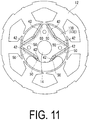
- Permanent magnets 42 and 50 are embedded in the rotor 13. Note that, although an arrangement example of the permanent magnets 42 and 50 is illustrated in FIG. 11 , the size, locations, orientations, and the like of the permanent magnets arranged in the rotor 13 are not limited to the arrangement example illustrated in FIG. 11 .
- the permanent magnets 42 and 50 are arranged inside openings formed in the steel plates.
- the permanent magnets 42 are arranged so as to be displaced further toward the stator 12 located on the opposite side to the side where the first balance weight 35 is installed than the permanent magnets 50 provided in another steel plate 13E.
- the planar shape of the steel plate 13D and the planar shape of the steel plate 13E are identical to each other.
- the plurality of permanent magnets 50 provided in a section other than the upper side of the rotor 13 are provided point-symmetrically with each other centered around the axis of the drive shaft 14, in the same manner as permanent magnets arranged in a conventional rotor.
- the plurality of permanent magnets 42 provided on the upper side of the rotor 13 are arranged so as to be displaced toward the opposite side to the side where the first balance weight 35 is installed, so that the center of the point-symmetry of the permanent magnets 42 is also displaced toward the opposite side to the side where the first balance weight 35 is installed with respect to the axis of the drive shaft 14.
- the present invention is not limited to this example.
- the magnetic attraction force increases on the upper side of the rotor 13 in the direction that alleviates the bending of the drive shaft 14, namely, in the radial direction opposite to the first balance weight 35 with respect to the axis of the drive shaft 14.
- a magnetic force of the permanent magnets arranged remote from the first balance weight 35, with respect to the axis of the drive shaft 14, is larger than that of the permanent magnets arranged adjacent to the first balance weight 35 with respect to the axis of the drive shaft 14.
- the magnetic attraction force is generated in the direction that alleviates the bending of the drive shaft 14, namely, in the radial direction opposite to the first balance weight 35 with respect to the axis of the drive shaft 14, and the bending of the drive shaft 14 can thus be alleviated.
- the permanent magnets 42 which are arranged on the upper side of the rotor 13, are arranged such that the magnetic attraction force increases in the radial direction opposite to the first balance weight 35 with respect to the axis of the drive shaft 14, the permanent magnets arranged on the lower side of the rotor 13 may also be arranged in the same manner. In this case, the permanent magnets arranged on the lower side of the rotor 13 are arranged such that the magnetic attraction force increases in the radial direction opposite to the second balance weight 36 with respect to the axis of the drive shaft 14.
- the present invention is not limited to this type of compressor.
- the present invention may also be applied to a rotary compressor in which only one rotary-type compression mechanism is provided, or to a scroll compressor and the like, in which one or a plurality of scroll-type compression mechanisms are provided.
Abstract
Description
- The present invention relates to a compressor that is applied to an air conditioner and the like, and that includes a rotary-type compression portion and a motor.
- A compression portion of a compressor used in an air conditioner is driven by an electromagnetic motor. The electromagnetic motor is constituted of a rotor and a stator, and the rotor and the compression portion are connected to each other via a drive shaft (a shaft). The rotor of the motor rotates, which rotates the compression portion.
- One end of the drive shaft adjacent to the compression portion is fixed, and the other end of the drive shaft adjacent to the rotor is a free end. Further, for a rotary-type compressor, the drive shaft is provided with a crank pin (an eccentric pin) adjacent to the compression portion, and the crank pin is fitted into a roller of the compression portion. As a result, the center of gravity of the roller of the compression portion is eccentrically positioned with respect to an axis of the drive shaft, and is not positioned on the axis of the drive shaft. Therefore, in order to keep balance with a centrifugal force generated by the rotation of the roller, a balance weight is provided as a weight, on the upper surface or the lower surface of the rotor.
- In Patent Document 1 described below, a technology is disclosed in which the center of a drive shaft is displaced, with respect to the center of a rotor of a motor, toward a first balance weight provided on the upper surface of the rotor, in order to suppress a centrifugal whirling of the rotor to reduce vibration and noise from the rotor. Further, in
Patent Document 2, a technology is disclosed in which, in order to reduce vibration and noise during operation, a drive shaft is provided with a first section to which a rotor is mounted and a second section located adjacent to a cylinder chamber, and the central axis of the first section is displaced, with respect to the central axis of the second section, toward the opposite side to a side on which a balance weight is provided. -
- Patent Document 1: Japanese Unexamined Patent Application Publication No.
2006-200527A - Patent Document 2: Japanese Unexamined Patent Application Publication No.
2009-74464A - During the operation of a compressor, noise is generated by vibration caused by a bending eigenvalue of a drive shaft. This noise based on resonance is larger than noise caused by other vibrations generated in the drive shaft. Given the structure of the compressor, the drive shaft is not easily prevented from resonating at the eigenvalue. However, even when the resonance has occurred, reducing a bending amount of the drive shaft can suppress the vibration and reduce the noise.
- In light of the foregoing, an object of the present invention is to provide a compressor capable of reducing a bending amount of a drive shaft to reduce noise generated by vibration caused by a bending eigenvalue.
- A compressor according to a first aspect of the present invention includes: a compression portion; a motor portion including a rotor formed by a plurality of metal plates stacked on top of each other, and a stator provided around an outer circumferential portion of the rotor; and a drive shaft connecting the motor portion and the compression portion. The rotor includes a weight portion on a surface thereof on one side in an axial direction of the drive shaft. Of the stacked metal plates, the metal plate located adjacent to the weight portion protrudes toward the stator located remote from weight portion in a radial direction of the rotor with respect to an axis of the drive shaft.
- With this configuration, the stacked metal plate constituting a part of the rotor protrudes toward the stator located remote from the weight portion in the radial direction of the rotor. Therefore, when the rotor of the motor rotates, a magnetic attraction force generated adjacent to the stator is larger in a section from which the metal plates protrude than a magnetic attraction force in a section from which the metal plates do not protrude. As a result, even when a centrifugal force acts due to the weight portion at the time of rotation, since the magnetic attraction force is generated in a direction that alleviates bending of the drive shaft, the bending of the drive shaft can be alleviated, in comparison to a case in which the rotor does not have the section in which the metal plate protrudes. Note that the surface on which the weight portion is provided on the one side in the axial direction of the drive shaft is a surface on the opposite side to a surface located adjacent to the compression portion, for example.
- In the first aspect of the present invention, of the stacked metal plates, the metal plate located adjacent to the weight portion may be stacked so as to be displaced toward the stator located remote from the weight portion in the radial direction of the rotor with respect to the axis of the drive shaft.
- With this configuration, the stacked metal plate constituting a part of the rotor is stacked in a displaced manner so as to protrude toward the stator located remote from the weight portion. Therefore, when the rotor of the motor rotates, the magnetic attraction force generated adjacent to the stator is larger in a section where the metal plate is stacked so as to protrude than a magnetic attraction force in a section where the metal plate is not stacked so as to protrude.
- In the first aspect of the present invention, of the stacked metal plates, the metal plate located adjacent to the weight portion may have a metal coating applied thereto so as to protrude toward the stator located remote from the weight portion in the radial direction of the rotor with respect to the axis of the drive shaft.
- With this configuration, the stacked metal plate constituting a part of the rotor has the metal coating applied thereto so as to protrude toward the stator located remote from the weight portion. Therefore, when the rotor of the motor rotates, the magnetic attraction force generated adjacent to the stator is larger in a section to which the metal coating is applied than a magnetic attraction force in a section from which the metal plate does not protrude.
- In the first aspect of the present invention, a weight of a section of the metal plate located adjacent to the weight portion with respect to the axis of the drive shaft may be reduced, taking into account a weight of a section of the metal plate that protrudes in the radial direction of the rotor.
- With this configuration, even when the stacked metal plate protrudes toward the opposite side to the weight portion with respect to the axis of the drive shaft, a centrifugal force that acts on the compression portion and a centrifugal force that acts on the rotor can be balanced against each other.
- In the first aspect of the present invention, a second weight portion may be provided on a surface of the rotor on the other side opposite to the one side in the axial direction of the drive shaft. Of the stacked metal plates, the metal plate located adjacent to the second weight portion protrudes toward the stator located remote from the second weight portion in the radial direction of the rotor with respect to the axis of the drive shaft.
- With this configuration, the metal plate located adjacent to the second weight portion protrudes toward the stator located remote from the second weight portion in the radial direction of the rotor, and in addition to the above-described metal plate located adjacent to the weight portion, the magnetic attraction force generated adjacent to the stator becomes larger than a magnetic attraction force in a section from which the metal plate does not protrude. As a result, the bending of the drive shaft can be further alleviated than a case in which the rotor does not have the section from which the metal plate protrudes.
- A compressor according to a second aspect of the present invention includes: a compression portion; a motor portion including a rotor formed by a plurality of metal plates stacked on top of each other, and a stator provided around an outer circumferential portion of the rotor; and a drive shaft connecting the motor portion and the compression portion. The rotor includes a weight portion on a surface thereof located remote from the compression portion in an axial direction of the drive shaft and includes a plurality of permanent magnets therein. The permanent magnets provided remote from the compression portion in the axial direction of the drive shaft are arranged such that a magnetic force increases in a direction toward the stator located remote from the weight portion in a radial direction of the rotor with respect to an axis of the drive shaft.
- With this configuration, the magnetic force of the permanent magnets increases toward the stator located remote from the weight portion in the radial direction of the rotor. Therefore, when the rotor of the motor rotates, the magnetic attraction force generated adjacent to the stator is larger in a section where the magnetic force of the permanent magnets increases than a magnetic attraction force in the other section. As a result, even when the centrifugal force acts due to the weight portion at the time of rotation, because the increased magnetic attraction force is generated in the direction that alleviates the bending of the drive shaft, the bending of the drive shaft can be alleviated, in comparison to a case in which the rotor does not have the section where the magnetic force of the permanent magnets increases.
- In the second aspect of the present invention, the permanent magnets provided remote from the compression portion in the axial direction of the drive shaft may be arranged so as to be shifted toward the stator in the radial direction of the rotor, in comparison to the other permanent magnets, or have a larger magnetic force than a magnetic force of the other permanent magnets.
- With this configuration, the permanent magnets are arranged so as to be shifted toward the stator located remote from the weight portion in the radial direction of the rotor, in comparison to the other permanent magnets. Therefore, when the rotor of the motor rotates, the magnetic attraction force generated adjacent to the stator is larger in a section where the permanent magnets are arranged so to be shifted than a magnetic attraction force in a section where the permanent magnets are not shifted. In other words, because the magnetic force of the permanent magnets toward the stator located remote from the weight portion in the radial direction of the rotor is larger than a magnetic force of the other permanent magnets, when the rotor of the motor rotates, the magnetic attraction force generated adjacent to the stator is larger in a section where the magnetic force of the permanent magnets is larger than a magnetic attraction force in the other section, than in the other section.
- According to the present invention, the bending amount of the drive shaft can be reduced, and the noise generated by the vibration caused by the bending eigenvalue can thus be reduced.
-
-
FIG. 1 is a vertical cross-sectional view of a compressor according to a first embodiment of the present invention. -
FIG. 2 is a horizontal cross-sectional view of a compression mechanism of the compressor according to the first embodiment of the present invention. -
FIG. 3 is a schematic vertical cross-sectional view of a rotor and a motor of the compressor according to the first embodiment of the present invention. -
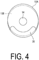
FIG. 4 is a plan view of the rotor of the compressor according to the first embodiment of the present invention. -
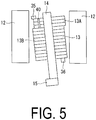
FIG. 5 is a schematic vertical cross-sectional view of a first modified example of the rotor and the motor of the compressor according to the first embodiment of the present invention. -
FIG. 6 is a plan view of the first modified example of the rotor of the compressor according to the first embodiment of the present invention. -
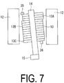
FIG. 7 is a schematic vertical cross-sectional view of a second modified example of the rotor and the motor of the compressor according to the first embodiment of the present invention. -
FIG. 8 is a plan view of the second modified example of the rotor of the compressor according to the first embodiment of the present invention. -
FIG. 9 is a schematic vertical cross-sectional view of a third modified example of the rotor and the motor of the compressor according to the first embodiment of the present invention. -
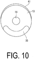
FIG. 10 is a plan view of the third modified example of the rotor of the compressor according to the first embodiment of the present invention. -
FIG. 11 is a horizontal cross-sectional view of a rotor and a motor of a compressor according to a second embodiment of the present invention. - A compressor 1 according to a first embodiment of the present invention will be described below with reference to the drawings. As illustrated in
FIG. 1 , the multi-cylinder rotary-type compressor 1 according to the present embodiment is provided with a cylindrical sealedcontainer 2 whose upper and lower portions are respectively sealed by anupper cover 3 and a lower cover 4. Amotor 5 is provided in the upper part of the interior of the sealedcontainer 2, and a compression mechanism (a rotary compression mechanism) 6 to be driven by themotor 5 is provided in the lower part of the sealedcontainer 2. - A mounting
leg 7 is provided on the outer circumference of the lower portion of the sealedcontainer 2. Further, a discharge pipe 8 that penetrates through theupper cover 3 is provided in the upper portion of the sealedcontainer 2. The discharge pipe 8 discharges a high-pressure refrigerant gas compressed by the multi-cylinder rotary compressor 1 toward a refrigeration cycle. Furthermore, anaccumulator 9 is mounted on an outer circumferential portion of the sealedcontainer 2. Theaccumulator 9 separates a liquid portion, such as oil and liquid refrigerant, contained in a low-pressure refrigerant gas returned from the refrigerating cycle side, and causes only a gas portion to be taken in by thecompressor mechanism 6 viaintake pipes - The
motor 5 is provided with astator 12 and arotor 13. Thestator 12 is fixedly installed on the inner circumferential surface of the sealedcontainer 2 by press fitting and the like. Therotor 13 is connected to and integrally provided with adrive shaft 14. This configuration allows a rotational driving force of therotor 13 to be transmitted to thecompression mechanism 6 via thedrive shaft 14. Further, in the lower part of thedrive shaft 14, a firsteccentric pin 15 and a secondeccentric pin 16 are provided so as to respectively correspond to afirst roller 24 and asecond roller 25 of the rotary-type compression mechanism 6 described below. - In the present embodiment, the rotary-
type compression mechanism 6 is of a two-cylinder type, and afirst cylinder chamber 17 and asecond cylinder chamber 18 are respectively formed in first and second compression mechanisms 6A and 6B of thecompression mechanism 6. Thecompression mechanism 6 is further provided with a first cylindermain body 19, a second cylindermain body 20, a partition plate (a separator plate) 21, anupper bearing 22, alower bearing 23, and the like. - The first cylinder
main body 19 and the second cylindermain body 20 are fixedly installed inside the sealedcontainer 2 so as to respectively correspond to the firsteccentric pin 15 and the secondeccentric pin 16 of thedrive shaft 14. The partition plate 21 is interposed between the first cylindermain body 19 and the second cylindermain body 20, defining thefirst cylinder chamber 17 and thesecond cylinder chamber 18. Theupper bearing 22 is provided on the upper surface of the first cylindermain body 19, defining thefirst cylinder chamber 17 and supporting thedrive shaft 14. Thelower bearing 23 is provided on the lower surface of the second cylindermain body 20, defining thesecond cylinder chamber 18 and supporting thedrive shaft 14. - The first and second compression mechanisms 6A and 6B are respectively provided with the
first roller 24 and thesecond roller 25 and withblades - The
first roller 24 and thesecond roller 25 are respectively rotatably fitted with the firsteccentric pin 15 and the secondeccentric pin 16, and rotate inside thefirst cylinder chamber 17 and thesecond cylinder chamber 18. The firsteccentric pin 15 and the secondeccentric pin 16 are connected to thedrive shaft 14 and rotate integrally with thedrive shaft 14. The center of gravity of thesecond roller 25 fitted with the secondeccentric pin 16 is positioned, with respect to an axis of thedrive shaft 14, remote from the center of gravity of thefirst roller 24 fitted with the firsteccentric pin 15. - As illustrated in
FIG. 2 , theblades blade grooves main body 19 and the second cylindermain body 20, and partition the interior of thefirst cylinder chamber 17 and thesecond cylinder chamber 18, respectively, into an intake chamber side and a discharge chamber side. - The low-pressure refrigerant gas is taken into the
first cylinder chamber 17 and thesecond cylinder chamber 18 of the first and second compression mechanisms 6A and 6B, from theintake pipes intake ports - The refrigerant gas taken into the
first cylinder chamber 17 and thesecond cylinder chamber 18 is compressed by the rotation of thefirst roller 24 and thesecond roller 25, and then discharged intodischarge chambers discharge chambers container 2, and then delivered to the refrigeration cycle via the discharge pipe 8. - The first cylinder
main body 19, the second cylindermain body 20, the partition plate 21, theupper bearing 22, and thelower bearing 23, which constitute thecompressor mechanism 6, are integrally tightened and fixed by bolts. Further, a bottom portion of the interior of the sealedcontainer 2 is filled withrefrigeration oil 34, such as PAG oil or POE oil. Therefrigeration oil 34 can be supplied to lubrication parts inside thecompressor mechanism 6 via oil supply holes and the like provided in thedrive shaft 14. An appropriate amount of an extreme-pressure agent suitable for each type of oil is added to therefrigeration oil 34. Note that, because an oil supply mechanism for thecompression mechanism 6 has a typical configuration, a detailed description thereof is omitted herein. - A
first balance weight 35 is provided on the upper surface of therotor 13, which is one side of thedrive shaft 14 in the axial direction thereof and is a surface located remote from thecompression mechanism 6. Further, the center of gravity of thefirst balance weight 35 is positioned, with respect to the axis of thedrive shaft 14, remote from the center of gravity of thefirst roller 24. Asecond balance weight 36 is provided on the lower surface of therotor 13, which is the other side of thedrive shaft 14 in the axial direction thereof and is a surface located adjacent to thecompression mechanism 6. Further, the center of gravity of thesecond balance weight 36 is positioned, with respect to the axis of thedrive shaft 14, remote from the center of gravity of thesecond roller 25. - As a result of the
first balance weight 35 and thesecond balance weight 36 being provided on the upper surface and the lower surface of therotor 13, a centrifugal force that acts on thefirst balance weight 35 and thesecond balance weight 36 can be balanced against a centrifugal force that is generated by the rotation of thefirst roller 24 and thesecond roller 25 and acts on thefirst roller 24 and thesecond roller 25. - The
rotor 13 is formed by a plurality of steel plates insulated from each other and stacked on top of each other in the axial direction of thedrive shaft 14. The steel plate is an example of a magnetic metal plate, and may be another magnetic metal plate. The steel plates stacked on top of each other suppress generation of an eddy current. Conventionally, the steel plates are arranged such that the outer surface of therotor 13 is on the same plane. Therefore, conventionally, a gap (also referred to as an air gap) formed between thestator 12 and therotor 13 is constant in the circumferential direction. The size of the air gap ranges, for example, from a hundred and several ten µm to several hundred µm in a manner that depends on the size of themotor 5 and the like. - Meanwhile, with respect to the air gap according to the present embodiment, when the rotation of the
rotor 13 is stopped, on the upper side of therotor 13, namely, on one side of thedrive shaft 14 in the axial direction thereof remote from thecompression mechanism 6, an air gap on a side on which thefirst balance weight 35 is installed is different from that on the opposite side to the side on which thefirst balance weight 35 is installed with respect to thedrive shaft 14. The air gap on the opposite side, with respect to thedrive shaft 14, to the side on which thefirst balance weight 35 is installed is narrower than that on the side on which thefirst balance weight 35 is installed. - For example, as illustrated in
FIGS. 3 and4 ,steel plates 13A, which are stacked on the upper side of therotor 13, are arranged in a displaced manner so as to protrude further toward thestator 12 located remote from the side on which thefirst balance weight 35 is installed, thanother steel plates 13B. Here, the planar shape of thesteel plate 13A and the planar shape of thesteel plate 13B are identical to each other. A displacement amount of thesteel plates 13A is approximately one tenth of the air gap, for example. Note thatFIG. 3 schematically illustrates a state in which therotor 13 centrifugally whirls with an end adjacent to thecompression mechanism 6 as a fixed end (the same state is illustrated below inFIGS. 5 ,7 , and9 ). - The number of the
steel plates 13A arranged in the displaced manner depends, for example, on a magnetic attraction force to be increased, and is the number of steel plates accounting for a range from several % to a little over 10% on the upper side of therotor 13. Note that the minimum number of thesteel plates 13A is assumed to be one, and the maximum number of thesteel plates 13A is assumed to be in a range from half to two-thirds of the total number of the steel plates. Note that, inFIG. 3 , a case is illustrated in which, as a displacement amount of thesteel plate 13A, the same value is applied to all of thesteel plates 13A arranged in the displaced manner. The displacement amount of thesteel plate 13A is not limited to this example. The displacement amount may be increased in a stepwise or continuous manner toward the upper side of therotor 13, and is not limited to the illustrated example in the drawing. - As a result of the
steel plates 13A stacked on the upper side of therotor 13 being arranged in the displaced manner, when the rotation of therotor 13 is stopped, the air gap on the opposite side, with respect to thedrive shaft 14, to the side on which thefirst balance weight 35 is installed is narrower than that on the side on which thefirst balance weight 35 is installed. As a result, because thesteel plates 13A of therotor 13 protrude toward the opposite side to thefirst balance weight 35, when therotor 13 of themotor 5 rotates, a larger magnetic attraction force is generated adjacent to thestator 12 over the protrusion section than over other sections. Specifically, even when the centrifugal force acts due to thefirst balance weight 35, as a result of thesteel plates 13A being arranged in the displaced manner as described above, the magnetic attraction force is generated in a direction that alleviates the bending of thedrive shaft 14, namely, in the opposite direction to thefirst balance weight 35 with respect to the axis of thedrive shaft 14, and the bending of thedrive shaft 14 can thus be alleviated. - As a result, even when the
drive shaft 14 resonates at an eigenvalue, compared with a case in which the steel plate is not arranged in the displaced manner, the bending amount of thedrive shaft 14 can be reduced, and noise generated by vibration caused by a bending eigenvalue can thus be reduced. - Taking into account the protrusion section of the
steel plates 13A, the weight of a section of thesteel plate 13 of therotor 13 located adjacent to thefirst balance weight 35 with respect to the axis of thedrive shaft 14 may be reduced. InFIGS. 5 and6 , an example is illustrated in which the formation of a through-hole 40 in each of thesteel plates 13A reduces the weight of thesteel plates 13A. - When the
steel plates 13A are arranged in the displaced manner, the magnetic attraction force can be increased. However, compared with a case in which thesteel plates 13A are not displaced, a balance with the centrifugal force acting on thefirst roller 24 and thesecond roller 25 may worsen. Note that, because the weight of the protrusion section is smaller than that of thefirst balance weight 35, a degree by which the balance worsens is estimated not to be significantly large. - As illustrated in
FIGS. 5 and6 , the formation of the through-hole 40 enables the centrifugal force acting on the upper part of therotor 13 to be balanced against the centrifugal force generated by the rotation of thefirst roller 24 and thesecond roller 25 and acting on thefirst roller 24 and thesecond roller 25. - Note that, in
FIGS. 5 and6 , although a case is illustrated in which the through-hole 40 is provided in all of thesteel plates 13A protruding toward thestator 12 located remote from thefirst balance weight 35, the present invention is not limited to this example. Specifically, the through-hole 40 may be provided in some of thesteel plates 13A. Further, instead of providing the through-hole 40 in thesteel plates 13A, the weight of thefirst balance weight 35 itself may be reduced, taking into account the protrusion section of thesteel plates 13A. - Although the compressor according to the first embodiment of the present invention is described above, the present invention is not limited to the configuration of the above-described embodiment.
- For example, in the above-described embodiment, although the air gap on the upper side of the
rotor 13 is narrowed in order to reduce the bending generated by the centrifugal force of thefirst balance weight 35, the present invention is not limited to this example. - For example, as illustrated in
FIGS. 7 and8 , a steel plate 13C stacked on the lower side of therotor 13 may be arranged in a displaced manner so as to protrude further toward thestator 12 located remote from the side on which thesecond balance weight 36 is installed, than theother steel plates 13B located in the intermediate section of therotor 13. As a result, when the rotation of therotor 13 is stopped, on the lower side of therotor 13, namely, on the other side in the axial direction of thedrive shaft 14, that is, on the side adjacent to thecompression mechanism 6, the air gap on the side remote from the side on which thesecond balance weight 36 is installed, with respect to thedrive shaft 14, is narrower than that on the side on which thesecond balance weight 36 is installed. - As a result, because the steel plate 13C of the
rotor 13 protrudes toward the side remote from thesecond balance weight 36, when therotor 13 of themotor 5 rotates, a larger magnetic attraction force is generated adjacent to thestator 12 over the protrusion section than over the other sections. Specifically, even when the centrifugal force acts due to thesecond balance weight 36, and the bending of thedrive shaft 14 occurs, as a result of the steel plate 13C being arranged in the displaced manner as described above, the magnetic attraction force is generated in the direction that alleviates the bending of thedrive shaft 14, namely, in the radial direction opposite to thesecond balance weight 36 with respect to the axis of thedrive shaft 14, and the bending of thedrive shaft 14 can thus be alleviated. - As described above, arranging the steel plate 13C of the
rotor 13 in the displaced manner allows, when thedrive shaft 14 resonates at the eigenvalue, the bending amount of thedrive shaft 14 to be reduced, and allows, when the steel plate 13C and thesteel plates 13A of therotor 13 are displaced at the same time, the noise generated by the vibration caused by the bending eigenvalue to be further reduced. Note that, when the bending amount of thedrive shaft 14 is larger on the lower side of therotor 13, only the steel plate 13C of therotor 13 may be arranged so as to be displaced. - Further, although, in the above-described embodiment, the
steel plates 13A stacked on the upper side of therotor 13 are arranged in the displaced manner so as to protrude further toward the opposite side to the side where thefirst balance weight 35 is installed than the other steel plates, the present invention is not limited to this example. Specifically, it is sufficient that, when the rotation of therotor 13 is stopped, the air gap on the opposite side to the side where thefirst balance weight 35 is installed, with respect to thedrive shaft 14, is caused to be narrower than that on the side where thefirst balance weight 35 is installed. For example, as illustrated inFIGS. 9 and10 , aprotrusion section 41 may be provided on an outer circumferential portion of thesteel plate 13A by separately applying a coating thereto. In this case, theprotrusion section 41 is formed by a silver paste or the like. Alternatively, theprotrusion section 41 may be formed by changing the planar shape of thesteel plate 13A itself to be different from that of thesteel plate 13B in the other section. - Of the stacked
steel plates 13A, theprotrusion section 41 is formed on the opposite side to the side where thefirst balance weight 35 is installed with respect to thedrive shaft 14. As a result, when the rotation of therotor 13 is stopped, the air gap on the opposite side to the side where thefirst balance weight 35 is installed, with respect to thedrive shaft 14, is narrower than that on the side where thefirst balance weight 35 is installed. As a result, because theprotrusion section 41 of thesteel plates 13A of therotor 13 protrudes toward a side remote from thefirst balance weight 35, when therotor 13 of themotor 5 rotates, a larger magnetic attraction force is generated adjacent to thestator 12 over theprotrusion section 41 than over the other sections. Specifically, even when the centrifugal force acts due to thefirst balance weight 35, and the bending of thedrive shaft 14 occurs, as a result of theprotrusion section 41 being formed as described above, the magnetic attraction force is generated in the direction that alleviates the bending of thedrive shaft 14, namely, in the direction toward thestator 12 located remote from thefirst balance weight 35 with respect to the axis of thedrive shaft 14, and the bending of thedrive shaft 14 can thus be alleviated. - As a result, even when the
drive shaft 14 resonates at the eigenvalue, the bending amount of thedrive shaft 14 can be reduced, and the noise generated by the vibration caused by the bending eigenvalue can thus be reduced. - Next, a compressor according to a second embodiment of the present invention will be described. In the compressor according to the present embodiment, the
rotor 13 is different from therotor 13 of the compressor according to the above-described first embodiment, and therefore therotor 13 according to the present embodiment will be described below. Because the structural members other than therotor 13 are the same as those of the first embodiment, a detailed description thereof will be omitted. - The
rotor 13 is formed by a plurality of steel plates insulated from each other and stacked on top of each other in the axial direction of thedrive shaft 14. The steel plates stacked on top of each other suppress generation of an eddy current. Each of the steel plates according to the present embodiment is arranged such that the outer surface of therotor 13 is on the same plane. Therefore, the gap (air gap) formed between thestator 12 and therotor 13 is constant in the circumferential direction. -
Permanent magnets rotor 13. Note that, although an arrangement example of thepermanent magnets FIG. 11 , the size, locations, orientations, and the like of the permanent magnets arranged in therotor 13 are not limited to the arrangement example illustrated inFIG. 11 . - The
permanent magnets steel plate 13D stacked on the upper side of therotor 13, thepermanent magnets 42 are arranged so as to be displaced further toward thestator 12 located on the opposite side to the side where thefirst balance weight 35 is installed than thepermanent magnets 50 provided in anothersteel plate 13E. Here, the planar shape of thesteel plate 13D and the planar shape of thesteel plate 13E are identical to each other. - Specifically, the plurality of
permanent magnets 50 provided in a section other than the upper side of therotor 13 are provided point-symmetrically with each other centered around the axis of thedrive shaft 14, in the same manner as permanent magnets arranged in a conventional rotor. Meanwhile, as described above, the plurality ofpermanent magnets 42 provided on the upper side of therotor 13 are arranged so as to be displaced toward the opposite side to the side where thefirst balance weight 35 is installed, so that the center of the point-symmetry of thepermanent magnets 42 is also displaced toward the opposite side to the side where thefirst balance weight 35 is installed with respect to the axis of thedrive shaft 14. - As a result, when the
rotor 13 of themotor 5 rotates, a larger magnetic attraction force is generated adjacent to thestator 12 in the upper side of therotor 13 than in the other sections of therotor 13. Specifically, even when the centrifugal force acts due to thefirst balance weight 35, and the bending of thedrive shaft 14 occurs, as a result of thepermanent magnets 42 being arranged in the displaced manner as described above, the magnetic attraction force is generated in the direction that alleviates the bending of thedrive shaft 14, namely, in the radial direction opposite to thefirst balance weight 35 with respect to the axis of thedrive shaft 14, and the bending of thedrive shaft 14 can thus be alleviated. - As a result, even when the
drive shaft 14 resonates at the eigenvalue, the bending amount of thedrive shaft 14 can be reduced, and the noise generated by the vibration caused by the bending eigenvalue can thus be reduced. - With respect to the compressor according to the second embodiment of the present invention, although an example is described in which the
permanent magnets 42 are arranged in the displaced manner on the upper side of therotor 13 in order to reduce the bending caused by the centrifugal force of thefirst balance weight 35, the present invention is not limited to this example. - Specifically, it is sufficient that the magnetic attraction force increases on the upper side of the
rotor 13 in the direction that alleviates the bending of thedrive shaft 14, namely, in the radial direction opposite to thefirst balance weight 35 with respect to the axis of thedrive shaft 14. For example, a magnetic force of the permanent magnets arranged remote from thefirst balance weight 35, with respect to the axis of thedrive shaft 14, is larger than that of the permanent magnets arranged adjacent to thefirst balance weight 35 with respect to the axis of thedrive shaft 14. - In this case also, the magnetic attraction force is generated in the direction that alleviates the bending of the
drive shaft 14, namely, in the radial direction opposite to thefirst balance weight 35 with respect to the axis of thedrive shaft 14, and the bending of thedrive shaft 14 can thus be alleviated. - Further, in the above-described embodiment, although an example is described in which the
permanent magnets 42, which are arranged on the upper side of therotor 13, are arranged such that the magnetic attraction force increases in the radial direction opposite to thefirst balance weight 35 with respect to the axis of thedrive shaft 14, the permanent magnets arranged on the lower side of therotor 13 may also be arranged in the same manner. In this case, the permanent magnets arranged on the lower side of therotor 13 are arranged such that the magnetic attraction force increases in the radial direction opposite to thesecond balance weight 36 with respect to the axis of thedrive shaft 14. - Further, although, with respect to the above-described compressors according to the first and second embodiments, a case is described in which the multi-cylinder rotary compressor is used as the compressor, the present invention is not limited to this type of compressor. For example, the present invention may also be applied to a rotary compressor in which only one rotary-type compression mechanism is provided, or to a scroll compressor and the like, in which one or a plurality of scroll-type compression mechanisms are provided.
-
- 1 Compressor
- 2 Sealed container
- 5 Motor (motor portion)
- 6 Compression mechanism (compression portion)
- 6A First compression mechanism
- 6B Second compression mechanism
- 8 Discharge pipe
- 9 Accumulator
- 10, 11 Intake pipe
- 12 Stator
- 13 Rotor
- 13A, 13B, 13C, 13D, 13E Steel plate
- 14 Drive shaft
- 15 First eccentric pin
- 16 Second eccentric pin
- 17 First cylinder chamber
- 18 Second cylinder chamber
- 19 First cylinder main body
- 20 Second cylinder main body
- 24 First roller
- 25 Second roller
- 35 First balance weight (weight portion)
- 36 Second balance weight (second weight portion)
- 40 Through-hole
- 41 Protrusion section
- 42, 50 Permanent magnet
Claims (7)
- A compressor comprising:a compression portion;a motor portion including a rotor formed by a plurality of metal plates stacked on top of each other, and a stator provided around an outer circumferential portion of the rotor; anda drive shaft connecting the motor portion and the compression portion,the rotor including a weight portion on a surface thereof on one side in an axial direction of the drive shaft, andof the stacked metal plates, the metal plate located adjacent to the weight portion protruding toward the stator located remote from the weight portion in a radial direction of the rotor with respect to an axis of the drive shaft.
- The compressor according to claim 1, wherein,
of the stacked metal plates, the metal plate located adjacent to the weight portion is stacked so as to be displaced toward the stator located remote from the weight portion in the radial direction of the rotor with respect to the axis of the drive shaft. - The compressor according to claim 1, wherein,
of the stacked metal plates, the metal plate located adjacent to the weight portion has a metal coating applied thereto so as to protrude toward the stator located remote from the weight portion in the radial direction of the rotor with respect to the axis of the drive shaft. - The compressor according to any one of claims 1 to 3, wherein
a weight of a section of the metal plate located adjacent to the weight portion with respect to the axis of the drive shaft is reduced, taking into account a weight of a section of the metal plate that protrudes in the radial direction of the rotor. - The compressor according to any one of claims 1 to 4, wherein
a second weight portion is provided on a surface of the rotor on an other side opposite to the one side in the axial direction of the drive shaft, and of the stacked metal plates, the metal plate located adjacent to the second weight portion protrudes toward the stator located remote from the second weight portion in the radial direction of the rotor with respect to the axis of the drive shaft. - A compressor comprising:a compression portion;a motor portion including a rotor formed by a plurality of metal plates stacked on top of each other, and a stator provided around an outer circumferential portion of the rotor; anda drive shaft connecting the motor portion and the compression portion,the rotor including a weight portion on a surface thereof located remote from the compression portion in an axial direction of the drive shaft and including a plurality of permanent magnets therein, and the permanent magnets provided remote from the compression portion in the axial direction of the drive shaft being arranged such that a magnetic force increases in a direction toward the stator located remote from the weight portion in a radial direction of the rotor with respect to an axis of the drive shaft in comparison to a magnetic force of other permanent magnets.
- The compressor according to claim 6, wherein
the permanent magnets provided remote from the compression portion in the axial direction of the drive shaft are arranged so as to be shifted toward the stator in the radial direction of the rotor in comparison to the other permanent magnets or have a larger magnetic force than a magnetic force of the other permanent magnets.
Applications Claiming Priority (2)
| Application Number | Priority Date | Filing Date | Title |
|---|---|---|---|
| JP2014251738A JP6502078B2 (en) | 2014-12-12 | 2014-12-12 | Compressor |
| PCT/JP2015/072828 WO2016092906A1 (en) | 2014-12-12 | 2015-08-12 | Compressor |
Publications (3)
| Publication Number | Publication Date |
|---|---|
| EP3217014A1 true EP3217014A1 (en) | 2017-09-13 |
| EP3217014A4 EP3217014A4 (en) | 2018-01-10 |
| EP3217014B1 EP3217014B1 (en) | 2019-05-22 |
Family
ID=56107104
Family Applications (1)
| Application Number | Title | Priority Date | Filing Date |
|---|---|---|---|
| EP15866661.0A Active EP3217014B1 (en) | 2014-12-12 | 2015-08-12 | Compressor |
Country Status (4)
| Country | Link |
|---|---|
| EP (1) | EP3217014B1 (en) |
| JP (1) | JP6502078B2 (en) |
| CN (1) | CN107076149A (en) |
| WO (1) | WO2016092906A1 (en) |
Families Citing this family (1)
| Publication number | Priority date | Publication date | Assignee | Title |
|---|---|---|---|---|
| JP6823096B2 (en) * | 2019-02-27 | 2021-01-27 | シナノケンシ株式会社 | Inner rotor type motor rotor |
Family Cites Families (8)
| Publication number | Priority date | Publication date | Assignee | Title |
|---|---|---|---|---|
| JPS57208842A (en) * | 1981-06-19 | 1982-12-22 | Toshiba Corp | Stacking method of iron core |
| JPS6413282U (en) * | 1987-07-14 | 1989-01-24 | ||
| JP2002272073A (en) * | 2001-03-08 | 2002-09-20 | Nissan Motor Co Ltd | Rotating electric machine |
| JP2006507941A (en) * | 2002-11-13 | 2006-03-09 | デカ プロダックツ リミテッド パートナーシップ | Distillation using vapor compression |
| JP2006042544A (en) * | 2004-07-29 | 2006-02-09 | Matsushita Electric Ind Co Ltd | Sealed motor compressor |
| JP5080287B2 (en) * | 2008-01-09 | 2012-11-21 | 株式会社日立産機システム | Compressor motor |
| JP6089412B2 (en) * | 2012-02-24 | 2017-03-08 | ダイキン工業株式会社 | Compressor |
| JP2014128101A (en) * | 2012-12-26 | 2014-07-07 | Toyota Industries Corp | Motor-driven compressor |
-
2014
- 2014-12-12 JP JP2014251738A patent/JP6502078B2/en active Active
-
2015
- 2015-08-12 CN CN201580060639.1A patent/CN107076149A/en active Pending
- 2015-08-12 WO PCT/JP2015/072828 patent/WO2016092906A1/en active Application Filing
- 2015-08-12 EP EP15866661.0A patent/EP3217014B1/en active Active
Also Published As
| Publication number | Publication date |
|---|---|
| EP3217014B1 (en) | 2019-05-22 |
| JP6502078B2 (en) | 2019-04-17 |
| JP2016113923A (en) | 2016-06-23 |
| EP3217014A4 (en) | 2018-01-10 |
| CN107076149A (en) | 2017-08-18 |
| WO2016092906A1 (en) | 2016-06-16 |
Similar Documents
| Publication | Publication Date | Title |
|---|---|---|
| US8814546B2 (en) | Compressor | |
| EP2749735B1 (en) | Compressor | |
| JP5441982B2 (en) | Rotary compressor | |
| US9145890B2 (en) | Rotary compressor with dual eccentric portion | |
| JP5114709B2 (en) | Hermetic scroll compressor and its assembly method | |
| US20150184652A1 (en) | Rotary machine and compressor | |
| CN107949701B (en) | Compressor | |
| EP3217014B1 (en) | Compressor | |
| EP3572670B1 (en) | Scroll compressor | |
| US9181947B2 (en) | Compressor | |
| KR101380987B1 (en) | Rotary compressor | |
| US20120128511A1 (en) | Compressor | |
| KR101563368B1 (en) | compressor | |
| WO2018131436A1 (en) | Compressor comprising shaft support | |
| WO2019021432A1 (en) | Scroll compressor | |
| JP5559839B2 (en) | Hermetic scroll compressor | |
| KR20110035823A (en) | Rotary compressor and its manufacturing method | |
| KR20110015856A (en) | Compressor | |
| CN107131126B (en) | Double-cylinder type hermetic compressor | |
| CN109923308B (en) | Compressor with a compressor housing having a plurality of compressor blades | |
| JP6673491B2 (en) | Hermetic compressor | |
| JP2013181516A (en) | Scroll compressor | |
| KR101698085B1 (en) | Hermetic compressor | |
| KR20110015855A (en) | Compressor | |
| KR20090012861A (en) | Two stage rotary compressor |
Legal Events
| Date | Code | Title | Description |
|---|---|---|---|
| STAA | Information on the status of an ep patent application or granted ep patent |
Free format text: STATUS: THE INTERNATIONAL PUBLICATION HAS BEEN MADE |
|
| PUAI | Public reference made under article 153(3) epc to a published international application that has entered the european phase |
Free format text: ORIGINAL CODE: 0009012 |
|
| STAA | Information on the status of an ep patent application or granted ep patent |
Free format text: STATUS: REQUEST FOR EXAMINATION WAS MADE |
|
| 17P | Request for examination filed |
Effective date: 20170522 |
|
| AK | Designated contracting states |
Kind code of ref document: A1 Designated state(s): AL AT BE BG CH CY CZ DE DK EE ES FI FR GB GR HR HU IE IS IT LI LT LU LV MC MK MT NL NO PL PT RO RS SE SI SK SM TR |
|
| AX | Request for extension of the european patent |
Extension state: BA ME |
|
| RAP1 | Party data changed (applicant data changed or rights of an application transferred) |
Owner name: MITSUBISHI HEAVY INDUSTRIES THERMAL SYSTEMS, LTD. |
|
| A4 | Supplementary search report drawn up and despatched |
Effective date: 20171212 |
|
| RIC1 | Information provided on ipc code assigned before grant |
Ipc: F04C 29/00 20060101ALI20171201BHEP Ipc: F04C 23/02 20060101AFI20171201BHEP |
|
| DAV | Request for validation of the european patent (deleted) | ||
| DAX | Request for extension of the european patent (deleted) | ||
| STAA | Information on the status of an ep patent application or granted ep patent |
Free format text: STATUS: EXAMINATION IS IN PROGRESS |
|
| 17Q | First examination report despatched |
Effective date: 20180905 |
|
| GRAP | Despatch of communication of intention to grant a patent |
Free format text: ORIGINAL CODE: EPIDOSNIGR1 |
|
| STAA | Information on the status of an ep patent application or granted ep patent |
Free format text: STATUS: GRANT OF PATENT IS INTENDED |
|
| INTG | Intention to grant announced |
Effective date: 20190212 |
|
| GRAS | Grant fee paid |
Free format text: ORIGINAL CODE: EPIDOSNIGR3 |
|
| GRAA | (expected) grant |
Free format text: ORIGINAL CODE: 0009210 |
|
| STAA | Information on the status of an ep patent application or granted ep patent |
Free format text: STATUS: THE PATENT HAS BEEN GRANTED |
|
| AK | Designated contracting states |
Kind code of ref document: B1 Designated state(s): AL AT BE BG CH CY CZ DE DK EE ES FI FR GB GR HR HU IE IS IT LI LT LU LV MC MK MT NL NO PL PT RO RS SE SI SK SM TR |
|
| REG | Reference to a national code |
Ref country code: GB Ref legal event code: FG4D |
|
| REG | Reference to a national code |
Ref country code: CH Ref legal event code: EP |
|
| REG | Reference to a national code |
Ref country code: IE Ref legal event code: FG4D |
|
| REG | Reference to a national code |
Ref country code: AT Ref legal event code: REF Ref document number: 1136448 Country of ref document: AT Kind code of ref document: T Effective date: 20190615 |
|
| REG | Reference to a national code |
Ref country code: DE Ref legal event code: R096 Ref document number: 602015030984 Country of ref document: DE |
|
| REG | Reference to a national code |
Ref country code: NL Ref legal event code: MP Effective date: 20190522 |
|
| REG | Reference to a national code |
Ref country code: LT Ref legal event code: MG4D |
|
| PG25 | Lapsed in a contracting state [announced via postgrant information from national office to epo] |
Ref country code: NO Free format text: LAPSE BECAUSE OF FAILURE TO SUBMIT A TRANSLATION OF THE DESCRIPTION OR TO PAY THE FEE WITHIN THE PRESCRIBED TIME-LIMIT Effective date: 20190822 Ref country code: FI Free format text: LAPSE BECAUSE OF FAILURE TO SUBMIT A TRANSLATION OF THE DESCRIPTION OR TO PAY THE FEE WITHIN THE PRESCRIBED TIME-LIMIT Effective date: 20190522 Ref country code: PT Free format text: LAPSE BECAUSE OF FAILURE TO SUBMIT A TRANSLATION OF THE DESCRIPTION OR TO PAY THE FEE WITHIN THE PRESCRIBED TIME-LIMIT Effective date: 20190922 Ref country code: AL Free format text: LAPSE BECAUSE OF FAILURE TO SUBMIT A TRANSLATION OF THE DESCRIPTION OR TO PAY THE FEE WITHIN THE PRESCRIBED TIME-LIMIT Effective date: 20190522 Ref country code: SE Free format text: LAPSE BECAUSE OF FAILURE TO SUBMIT A TRANSLATION OF THE DESCRIPTION OR TO PAY THE FEE WITHIN THE PRESCRIBED TIME-LIMIT Effective date: 20190522 Ref country code: HR Free format text: LAPSE BECAUSE OF FAILURE TO SUBMIT A TRANSLATION OF THE DESCRIPTION OR TO PAY THE FEE WITHIN THE PRESCRIBED TIME-LIMIT Effective date: 20190522 Ref country code: ES Free format text: LAPSE BECAUSE OF FAILURE TO SUBMIT A TRANSLATION OF THE DESCRIPTION OR TO PAY THE FEE WITHIN THE PRESCRIBED TIME-LIMIT Effective date: 20190522 Ref country code: LT Free format text: LAPSE BECAUSE OF FAILURE TO SUBMIT A TRANSLATION OF THE DESCRIPTION OR TO PAY THE FEE WITHIN THE PRESCRIBED TIME-LIMIT Effective date: 20190522 Ref country code: NL Free format text: LAPSE BECAUSE OF FAILURE TO SUBMIT A TRANSLATION OF THE DESCRIPTION OR TO PAY THE FEE WITHIN THE PRESCRIBED TIME-LIMIT Effective date: 20190522 |
|
| PG25 | Lapsed in a contracting state [announced via postgrant information from national office to epo] |
Ref country code: RS Free format text: LAPSE BECAUSE OF FAILURE TO SUBMIT A TRANSLATION OF THE DESCRIPTION OR TO PAY THE FEE WITHIN THE PRESCRIBED TIME-LIMIT Effective date: 20190522 Ref country code: GR Free format text: LAPSE BECAUSE OF FAILURE TO SUBMIT A TRANSLATION OF THE DESCRIPTION OR TO PAY THE FEE WITHIN THE PRESCRIBED TIME-LIMIT Effective date: 20190823 Ref country code: BG Free format text: LAPSE BECAUSE OF FAILURE TO SUBMIT A TRANSLATION OF THE DESCRIPTION OR TO PAY THE FEE WITHIN THE PRESCRIBED TIME-LIMIT Effective date: 20190822 Ref country code: LV Free format text: LAPSE BECAUSE OF FAILURE TO SUBMIT A TRANSLATION OF THE DESCRIPTION OR TO PAY THE FEE WITHIN THE PRESCRIBED TIME-LIMIT Effective date: 20190522 |
|
| REG | Reference to a national code |
Ref country code: AT Ref legal event code: MK05 Ref document number: 1136448 Country of ref document: AT Kind code of ref document: T Effective date: 20190522 |
|
| PG25 | Lapsed in a contracting state [announced via postgrant information from national office to epo] |
Ref country code: CZ Free format text: LAPSE BECAUSE OF FAILURE TO SUBMIT A TRANSLATION OF THE DESCRIPTION OR TO PAY THE FEE WITHIN THE PRESCRIBED TIME-LIMIT Effective date: 20190522 Ref country code: RO Free format text: LAPSE BECAUSE OF FAILURE TO SUBMIT A TRANSLATION OF THE DESCRIPTION OR TO PAY THE FEE WITHIN THE PRESCRIBED TIME-LIMIT Effective date: 20190522 Ref country code: SK Free format text: LAPSE BECAUSE OF FAILURE TO SUBMIT A TRANSLATION OF THE DESCRIPTION OR TO PAY THE FEE WITHIN THE PRESCRIBED TIME-LIMIT Effective date: 20190522 Ref country code: DK Free format text: LAPSE BECAUSE OF FAILURE TO SUBMIT A TRANSLATION OF THE DESCRIPTION OR TO PAY THE FEE WITHIN THE PRESCRIBED TIME-LIMIT Effective date: 20190522 Ref country code: AT Free format text: LAPSE BECAUSE OF FAILURE TO SUBMIT A TRANSLATION OF THE DESCRIPTION OR TO PAY THE FEE WITHIN THE PRESCRIBED TIME-LIMIT Effective date: 20190522 Ref country code: EE Free format text: LAPSE BECAUSE OF FAILURE TO SUBMIT A TRANSLATION OF THE DESCRIPTION OR TO PAY THE FEE WITHIN THE PRESCRIBED TIME-LIMIT Effective date: 20190522 |
|
| REG | Reference to a national code |
Ref country code: DE Ref legal event code: R097 Ref document number: 602015030984 Country of ref document: DE |
|
| PG25 | Lapsed in a contracting state [announced via postgrant information from national office to epo] |
Ref country code: IT Free format text: LAPSE BECAUSE OF FAILURE TO SUBMIT A TRANSLATION OF THE DESCRIPTION OR TO PAY THE FEE WITHIN THE PRESCRIBED TIME-LIMIT Effective date: 20190522 Ref country code: SM Free format text: LAPSE BECAUSE OF FAILURE TO SUBMIT A TRANSLATION OF THE DESCRIPTION OR TO PAY THE FEE WITHIN THE PRESCRIBED TIME-LIMIT Effective date: 20190522 |
|
| PLBE | No opposition filed within time limit |
Free format text: ORIGINAL CODE: 0009261 |
|
| STAA | Information on the status of an ep patent application or granted ep patent |
Free format text: STATUS: NO OPPOSITION FILED WITHIN TIME LIMIT |
|
| PG25 | Lapsed in a contracting state [announced via postgrant information from national office to epo] |
Ref country code: TR Free format text: LAPSE BECAUSE OF FAILURE TO SUBMIT A TRANSLATION OF THE DESCRIPTION OR TO PAY THE FEE WITHIN THE PRESCRIBED TIME-LIMIT Effective date: 20190522 |
|
| 26N | No opposition filed |
Effective date: 20200225 |
|
| PG25 | Lapsed in a contracting state [announced via postgrant information from national office to epo] |
Ref country code: PL Free format text: LAPSE BECAUSE OF FAILURE TO SUBMIT A TRANSLATION OF THE DESCRIPTION OR TO PAY THE FEE WITHIN THE PRESCRIBED TIME-LIMIT Effective date: 20190522 |
|
| PG25 | Lapsed in a contracting state [announced via postgrant information from national office to epo] |
Ref country code: SI Free format text: LAPSE BECAUSE OF FAILURE TO SUBMIT A TRANSLATION OF THE DESCRIPTION OR TO PAY THE FEE WITHIN THE PRESCRIBED TIME-LIMIT Effective date: 20190522 Ref country code: LI Free format text: LAPSE BECAUSE OF NON-PAYMENT OF DUE FEES Effective date: 20190831 Ref country code: CH Free format text: LAPSE BECAUSE OF NON-PAYMENT OF DUE FEES Effective date: 20190831 Ref country code: LU Free format text: LAPSE BECAUSE OF NON-PAYMENT OF DUE FEES Effective date: 20190812 Ref country code: MC Free format text: LAPSE BECAUSE OF FAILURE TO SUBMIT A TRANSLATION OF THE DESCRIPTION OR TO PAY THE FEE WITHIN THE PRESCRIBED TIME-LIMIT Effective date: 20190522 |
|
| REG | Reference to a national code |
Ref country code: BE Ref legal event code: MM Effective date: 20190831 |
|
| PG25 | Lapsed in a contracting state [announced via postgrant information from national office to epo] |
Ref country code: IE Free format text: LAPSE BECAUSE OF NON-PAYMENT OF DUE FEES Effective date: 20190812 |
|
| PG25 | Lapsed in a contracting state [announced via postgrant information from national office to epo] |
Ref country code: BE Free format text: LAPSE BECAUSE OF NON-PAYMENT OF DUE FEES Effective date: 20190831 |
|
| PG25 | Lapsed in a contracting state [announced via postgrant information from national office to epo] |
Ref country code: CY Free format text: LAPSE BECAUSE OF FAILURE TO SUBMIT A TRANSLATION OF THE DESCRIPTION OR TO PAY THE FEE WITHIN THE PRESCRIBED TIME-LIMIT Effective date: 20190522 |
|
| PG25 | Lapsed in a contracting state [announced via postgrant information from national office to epo] |
Ref country code: IS Free format text: LAPSE BECAUSE OF FAILURE TO SUBMIT A TRANSLATION OF THE DESCRIPTION OR TO PAY THE FEE WITHIN THE PRESCRIBED TIME-LIMIT Effective date: 20190922 |
|
| PG25 | Lapsed in a contracting state [announced via postgrant information from national office to epo] |
Ref country code: HU Free format text: LAPSE BECAUSE OF FAILURE TO SUBMIT A TRANSLATION OF THE DESCRIPTION OR TO PAY THE FEE WITHIN THE PRESCRIBED TIME-LIMIT; INVALID AB INITIO Effective date: 20150812 Ref country code: MT Free format text: LAPSE BECAUSE OF FAILURE TO SUBMIT A TRANSLATION OF THE DESCRIPTION OR TO PAY THE FEE WITHIN THE PRESCRIBED TIME-LIMIT Effective date: 20190522 |
|
| PG25 | Lapsed in a contracting state [announced via postgrant information from national office to epo] |
Ref country code: MK Free format text: LAPSE BECAUSE OF FAILURE TO SUBMIT A TRANSLATION OF THE DESCRIPTION OR TO PAY THE FEE WITHIN THE PRESCRIBED TIME-LIMIT Effective date: 20190522 |
|
| REG | Reference to a national code |
Ref country code: DE Ref legal event code: R082 Ref document number: 602015030984 Country of ref document: DE Representative=s name: CBDL PATENTANWAELTE GBR, DE |
|
| PGFP | Annual fee paid to national office [announced via postgrant information from national office to epo] |
Ref country code: GB Payment date: 20230629 Year of fee payment: 9 |
|
| PGFP | Annual fee paid to national office [announced via postgrant information from national office to epo] |
Ref country code: FR Payment date: 20230703 Year of fee payment: 9 Ref country code: DE Payment date: 20230627 Year of fee payment: 9 |