JP5114709B2 - Hermetic scroll compressor and its assembly method - Google Patents
Hermetic scroll compressor and its assembly method Download PDFInfo
- Publication number
- JP5114709B2 JP5114709B2 JP2007267231A JP2007267231A JP5114709B2 JP 5114709 B2 JP5114709 B2 JP 5114709B2 JP 2007267231 A JP2007267231 A JP 2007267231A JP 2007267231 A JP2007267231 A JP 2007267231A JP 5114709 B2 JP5114709 B2 JP 5114709B2
- Authority
- JP
- Japan
- Prior art keywords
- drive shaft
- balancer
- arc
- center
- motor
- Prior art date
- Legal status (The legal status is an assumption and is not a legal conclusion. Google has not performed a legal analysis and makes no representation as to the accuracy of the status listed.)
- Active
Links
Images


Landscapes
- Rotary Pumps (AREA)
Description
本発明は、密閉スクロール圧縮機およびその組立方法に関し、特に、密閉ケース内に収容される旋回スクロールに旋回運動を与える駆動軸回りの構造、および該駆動軸を旋回スクロールに組み付ける方法に関する。 The present invention relates to a hermetic scroll compressor and an assembling method thereof, and more particularly, to a structure around a drive shaft that imparts orbiting motion to a orbiting scroll accommodated in a hermetic case, and a method of assembling the driving shaft to the orbiting scroll.
スクロール圧縮機は、一般に、固定スクロールと旋回スクロールのそれぞれの端板に突設された固定スクロール翼と旋回スクロール翼とを互いに噛み合わせて複数の圧縮室を形成し、該旋回スクロールを駆動軸から軸心が偏心して形成されたクランク部によって旋回させて作動するように構成されている。
そして、固定スクロールはフレームに固定され、固定スクロールに対して旋回スクロールを自転させないで公転させるように、固定スクロールと旋回スクロールとの間にオルダム継手が介在されている。
In general, a scroll compressor forms a plurality of compression chambers by meshing fixed scroll blades and orbiting scroll blades projecting from respective end plates of the fixed scroll and the orbiting scroll to form a plurality of compression chambers. It is configured to rotate by a crank portion formed with an eccentric shaft center.
The fixed scroll is fixed to the frame, and an Oldham joint is interposed between the fixed scroll and the orbiting scroll so as to revolve without rotating the orbiting scroll with respect to the fixed scroll.
このように旋回スクロールは、駆動軸から軸心が偏心して形成されたクランク部によって旋回させられるため、旋回スクロールの旋回運動によって駆動軸には遠心力が生じるため、この遠心力によるアンバランスを打ち消すために駆動軸にはバランスウエイトが取付けられている。
密閉形スクロール圧縮機においては、一般的に駆動軸に対して上、中、下の3箇所にバランスウエイトを取付けてこのアンバランスを抑えているものが知られている。
In this way, the orbiting scroll is turned by the crank portion formed with its axis decentered from the drive shaft. Therefore, the turning force of the orbiting scroll generates a centrifugal force on the drive shaft, thereby canceling the unbalance due to the centrifugal force. Therefore, a balance weight is attached to the drive shaft.
A hermetic scroll compressor is generally known in which a balance weight is attached at three locations on the upper, middle and lower sides of the drive shaft to suppress this unbalance.
例えば、特開2004−270495号公報(特許文献1)には、図5示すように、旋回スクロール01の下面側の空間02内に、該空間02を略満たすような断面形状の上バランスウエイト03が回転軸(駆動軸)04に取付けられ、モータ05のロータ06上側(旋回スクロール側)には、中バランスウエイト07が、ロータ06下側(反旋回スクロール側)には、下バランスウエイト08がそれぞれ回転軸04に取付けられて、旋回スクロール01に旋回運動によるアンバランスを打ち消している。
For example, in Japanese Patent Application Laid-Open No. 2004-270495 (Patent Document 1), as shown in FIG. 5, an
また、この特許文献1には、前記上バランスウエイト03の形状が旋回スクロール01の下面側の空間02を略満たすようになっているため、該下面側の空間02に出入する潤滑油を最小限に抑えて該空間02内に潤滑油が溜まらないようにして不安定な遠心力を発生させる要因を排除して回転軸04に生じる回転運動のアンバランスの発生をも抑えている。
Further, in this
また、特開2004−204748号公報(特許文献2)においても、図6のように、旋回スクロール020の下面側の空間021内で、上バランスウエイト022が回転軸(駆動軸)023に取付けられ、モータ024のロータ025の上側には中バランスウエイト026が、ロータ025下側には下バランスウエイト027がそれぞれ回転軸023に取付けられて、旋回スクロール020に旋回運動によって生じる回転軸023のアンバランスを打ち消している。
また、この特許文献2には、各バランスウエイト022、026、027にそれぞれ調整部031を設けてバランスウエイトの微調整を可能にする構成が示されている。
Also in Japanese Patent Application Laid-Open No. 2004-204748 (Patent Document 2), the
Further, this
前記したように特許文献1、特許文献2には、それぞれ回転軸の上、中、下の位置の3箇所にバランスウエイトを取付けて旋回スクロールの旋回運動に伴って発生する回転主軸のアンバランスを抑えている構成が示されている。
しかし、特許文献1に示される回転軸04と上、中、下のバランスウエイト03、07、08との結合、および回転軸04を回転支持するフレーム部材09との支持構造では、回転軸04に上、中、下のバランスウエイト03、07、08、さらにはモータ05のロータ06を装着した状態で、圧縮機、すなわちフレーム部材09に組付けることができない。
すなわち、図5に示すようにフレーム部材09の軸受部010の貫通孔011の孔径では、上バランスウエイト03を通すことができない構造になっている。
As described above, in
However, in the support structure of the
That is, as shown in FIG. 5, the
予め、バランスウエイト03、07、08およびロータ06を回転軸04に装着できないため、回転軸04を軸受部010の貫通孔011に通した後にこれらバランスウエイト03、07、08およびロータ06を回転軸04に組付けなければならず、圧縮機の組立て工数が増大するとともに、圧縮機に回転軸04を組付けた後ロータ06やバランスウエイト03、07、08を焼嵌めや圧入を行うと、その焼嵌めや圧入の作業に伴って発生する熱による熱変形や、金属屑による摺動部の損傷などの問題が生じやすい。
Since the
また、図6に示す特許文献2の場合においても、特許文献1と同様に、回転軸023と回転軸023に上、中、下のバランスウエイト022、026、027、モータ024のロータ025、さらに軸受030を装着した状態で、フレーム部材028の貫通孔029に通過させることができない構造となっている。
従って、特許文献2においても、前記特許文献1で説明したような、圧縮機の組立て工数の増大とともに、熱変形や摺動部の損傷などの問題を生じやすい。
In the case of
Therefore, in
さらに、特許文献1、2においては、モータのロータに永久磁石が内蔵された、いわゆるIPMモータによって構成されることや、モータのロータについて回転軸をフレーム部材に組付ける前に回転軸に組み付けて磁化させる場合における組立ての安定性までは示されていない。
一般に、ロータに近接して配置された中、下バランウエイトは鉄系金属によって形成されているため、ロータの磁力によって磁化されやすく、モータのロータについて回転軸をフレーム部材に組付ける前に回転軸に組み付けて磁化させると、回転軸と一体となったバランサをフレームに組付ける際の組付け作業時に、他の部品に引き付けられて効率的な安定作業ができなくなる。また、IPMモータに金属くずが付着する問題も有している。
Further, in
In general, the lower balun weight is made of iron-based metal while being arranged close to the rotor, so it is easily magnetized by the magnetic force of the rotor, and the rotation shaft of the motor rotor before the rotation shaft is assembled to the frame member. If it is assembled and magnetized, the balancer integrated with the rotating shaft is attracted to other parts at the time of assembling work when assembling the balancer to the frame, and efficient stable work cannot be performed. There is also a problem that metal scraps adhere to the IPM motor.
そこで、本発明は、このような背景に鑑みてなされたものであり、駆動軸に取付けられる上、中、下のバランスウエイト、モータのロータ、さらには軸受を、駆動軸に予め装着した状態で、密閉形圧縮機のフレーム部材に取付けることができるようにした密閉スクロール圧縮機およびその組立方法を提供することを課題とする。 Therefore, the present invention has been made in view of such a background. In addition to being attached to the drive shaft, the middle and lower balance weights, the rotor of the motor, and the bearing are mounted on the drive shaft in advance. It is another object of the present invention to provide a hermetic scroll compressor that can be attached to a frame member of a hermetic compressor and an assembling method thereof.
また、モータのロータが永久磁石を内蔵した、いわゆるIPMモータの場合であって、組付け前に磁化される場合でも、磁化による引付力の影響を軽減して、安定した組立て作業ができる密閉スクロール圧縮機およびその組立方法を提供することを課題とする。 Further, even when the motor rotor is a so-called IPM motor with a built-in permanent magnet and is magnetized prior to assembly, the hermetically sealed operation can be reduced by reducing the influence of attracting force due to magnetization. It is an object of the present invention to provide a scroll compressor and an assembly method thereof.
前記課題を解決するため、本発明は、密閉ケース内に固定スクロールと旋回スクロールとからなる圧縮機構部と、前記旋回スクロールに駆動軸を介して回転駆動力を与えるモータと、前記旋回スクロールの背面側のフレーム部材に形成された円筒状の旋回空間内に配置されるとともに前記駆動軸に取付けられる上バランサと、前記モータの上側で前記駆動軸やロータの回転体に取付けられる中バランサと、前記モータの下側で前記駆動軸やロータの回転体に取付けられる下バランサとを備えた密閉形スクロール圧縮機において、前記上バランサと中バランサとの間に前記駆動軸を支える主軸受を取付け、前記フレーム部材の前記旋回空間の下方に前記主軸受が嵌合する軸受嵌合穴を形成し、該軸受嵌合穴の内径を前記旋回空間の内径より大きく前記旋回空間の軸心と一致させて形成して、前記主軸受、上、中、下バランサ、モータのロータを前記駆動軸に取付けた状態で、前記軸受を前記軸受嵌合穴に取付け可能に構成し、前記上バランサは前記駆動軸から径方向に突き出た円環部の周縁から軸方向に伸びる半円弧状の縦壁を有して形成されるともに、該半円弧状の縦壁の内側中央部には周方向溝が形成され、遠心力によって広がる潤滑油を該周方向溝に集めて前記縦壁に沿って前記旋回空間内に放出可能であり、前記縦壁の外壁面は外円弧で形成され、前記縦壁の内壁面は外側よりの第1内円弧と中央よりの第2内円弧とから形成され、前記外円弧の中心は前記駆動軸の中心におよそ一致させ、前記第1内円弧の中心は、前記外円弧の中心より前記縦壁の反対側に配置し、前記第2内円弧の中心は、前記外円弧の中心より前記縦壁側に配置して、前記第2内円弧の先端が前記外円弧と前記第1内円弧との間で形成されるように前記縦壁が形成されていることを特徴とする。 In order to solve the above-described problems, the present invention provides a compression mechanism unit including a fixed scroll and a turning scroll in a sealed case, a motor that applies a rotational driving force to the turning scroll via a drive shaft, and a rear surface of the turning scroll. An upper balancer which is disposed in a cylindrical swivel space formed in the frame member on the side and which is attached to the drive shaft; an intermediate balancer which is attached to the drive shaft and the rotor of the rotor on the upper side of the motor; In a hermetic scroll compressor having a lower balancer attached to the rotating body of the drive shaft or rotor below the motor, a main bearing supporting the drive shaft is attached between the upper balancer and the intermediate balancer, A bearing fitting hole for fitting the main bearing is formed below the orbiting space of the frame member, and the inner diameter of the bearing fitting hole is larger than the inner diameter of the orbiting space. It is formed so as to coincide with the axis of the orbiting space, and the bearing can be mounted in the bearing fitting hole with the main bearing, the upper, middle and lower balancers, and the motor rotor mounted on the drive shaft. The upper balancer is configured to have a semicircular arc-shaped vertical wall extending in the axial direction from the periphery of the annular portion protruding in the radial direction from the drive shaft, and the inner side of the semicircular arc-shaped vertical wall. A circumferential groove is formed in the center, and lubricating oil spreading by centrifugal force can be collected in the circumferential groove and discharged into the swirl space along the vertical wall, and the outer wall surface of the vertical wall is an outer arc. The inner wall surface of the vertical wall is formed of a first inner arc from the outside and a second inner arc from the center, and the center of the outer arc approximately coincides with the center of the drive shaft, The center of the inner arc is disposed on the opposite side of the vertical wall from the center of the outer arc, and the first arc The center of the inner arc is disposed closer to the vertical wall than the center of the outer arc, and the tip of the second inner arc is formed between the outer arc and the first inner arc. Is formed .
かかる発明によれば、前記上バランサと中バランサとの間の前記駆動軸に主軸受を取付け、前記フレーム部材の前記旋回空間の下方に前記主軸受が嵌合する軸受嵌合穴を形成し、該軸受嵌合穴の内径を前記旋回空間の内径より大きくかつ前記旋回空間の軸心と一致させて形成することによって、駆動軸に主軸受、上バランサ、中バランサ、下バランサ、さらにモータのロータを一体化した状態で、組付けが可能になるため、密閉形スクロール圧縮機の組立てが簡単化して、組立て工数が減少し生産効率が向上する。 According to this invention, a main bearing is attached to the drive shaft between the upper balancer and the middle balancer, and a bearing fitting hole into which the main bearing is fitted is formed below the turning space of the frame member, By forming the inner diameter of the bearing fitting hole to be larger than the inner diameter of the swirl space and to coincide with the axis of the swirl space, the main shaft, the upper balancer, the middle balancer, the lower balancer, and the rotor of the motor are provided on the drive shaft. Assembling is possible in a state where the components are integrated, so that the assembly of the hermetic scroll compressor is simplified, the number of assembling steps is reduced, and the production efficiency is improved.
さらには、スクロール圧縮機に駆動軸を組付けた後にロータやバランサを焼嵌めや圧入して後から取り付けると、その焼嵌めや圧入の作業に伴って発生する熱や金属屑によって熱変形や摺動部の損傷などが生じやすいという問題があるが、駆動軸に主軸受、上バランサ、中バランサ、下バランサ、さらにモータのロータを一体化した状態で、組付けが可能になるため、これら問題が解消されて熱変形や摺動部の損傷のない密閉形スクロール圧縮機を得ることができる。 Furthermore, if the rotor or balancer is shrink-fitted or press-fitted after the drive shaft is assembled to the scroll compressor and then attached later, the heat generated by the shrink-fitting or press-fitting operation or metal debris causes thermal deformation or sliding. There is a problem that the moving part is likely to be damaged, but it is possible to assemble with the drive shaft integrated with the main bearing, upper balancer, middle balancer, lower balancer, and motor rotor. Is eliminated, and a hermetic scroll compressor without thermal deformation or damage to the sliding portion can be obtained.
また、かかる構成によれば、前記旋回空間内に臨んで配置されたシール部材に対して、また潤滑部分に対して潤滑油を行き渡らせることができるため、シール性および潤滑性を向上することができる。 Further, according to whether this configuration, the seal member being disposed facing the said pivoting space, also it is possible to spread the lubricating oil to the lubricating portions, to improve the sealing property and lubricity Can do.
また、好ましくは、前記主軸受の下面側には環状のカバー部材が取付けられ、該カバー部材の内周縁は前記駆動軸近傍まで伸び、外周縁は前記モータを覆うように形成されていることを特徴とする。
かかる構成によれば、カバー部材によって、主軸受を経由して落下してきた潤滑油を該主軸受けの下方に配置されるモータのロータやコイルエンド等に直接降りかからないようにして、潤滑油がモータのロータによって攪拌されて、このモータの近傍に配置される密閉形スクロール圧縮機の吐出口から潤滑油が圧縮ガスとともに排出されることを防止している。
なお、前記カバー部材は外周縁が垂下して前記モータに接触しても導電しないように樹脂等の非導電性材料によって形成されていることが望ましい。
Preferably, an annular cover member is attached to the lower surface side of the main bearing, the inner peripheral edge of the cover member extends to the vicinity of the drive shaft, and the outer peripheral edge is formed to cover the motor. Features.
According to such a configuration, the lubricating oil is prevented from falling directly on the rotor or coil end of the motor disposed below the main bearing by the cover member so that the lubricating oil falling via the main bearing does not fall on the motor. The lubricating oil is prevented from being discharged together with the compressed gas from the discharge port of the hermetic scroll compressor disposed in the vicinity of the motor.
The cover member is preferably formed of a non-conductive material such as a resin so that the outer peripheral edge hangs down and does not conduct even if it contacts the motor.
次に、密閉形スクロール圧縮機の組立方法にかかる本発明は、密閉ケース内に固定スクロールと旋回スクロールとからなる圧縮機構部と、前記旋回スクロールに駆動軸を介して回転駆動力を与えるモータと、前記旋回スクロールの背面側のフレーム部材に形成された旋回空間内に配置されるとともに前記駆動軸に取付けられる上バランサと、前記モータの上側で前記駆動軸やロータの回転体に取付けられる中バランサと、前記モータの下側で前記駆動軸やロータの回転体に取付けられる下バランサとを備え、前記上バランサは前記駆動軸から径方向に突き出た円環部の周縁から軸方向に伸びる半円弧状の縦壁を有して形成されるともに、該半円弧状の縦壁の内側中央部には周方向溝が形成され、遠心力によって広がる潤滑油を該周方向溝に集めて前記縦壁に沿って前記旋回空間内に放出可能であり、前記縦壁の外壁面は外円弧で形成され、前記縦壁の内壁面は外側よりの第1内円弧と中央よりの第2内円弧とから形成され、前記外円弧の中心は前記駆動軸の中心におよそ一致させ、前記第1内円弧の中心は、前記外円弧の中心より前記縦壁の反対側に配置し、前記第2内円弧の中心は、前記外円弧の中心より前記縦壁側に配置して、前記第2内円弧の先端が前記外円弧と前記第1内円弧との間で形成されるように前記縦壁が形成されている密閉形スクロール圧縮機の組立方法であって、前記フレーム部材の前記旋回空間の下方に前記主軸受が嵌合する軸受嵌合穴を形成し、該嵌合穴の内径を前記旋回空間の内径より大きく前記旋回空間の軸心と一致させて形成し、前記上バランサと中バランサとの間に前記駆動軸を支える主軸受を、さらに前記上、中、下バランサ、モータのロータを前記駆動軸に取付けて一体化し、その後該一体化された部品を前記軸受嵌合穴に前記軸受をフレーム部材の下方から組付けることを特徴とする。
Next, the present invention according to the assembling method of the hermetic scroll compressor includes: a compression mechanism unit composed of a fixed scroll and a orbiting scroll in a hermetic case; and a motor for applying a rotational driving force to the orbiting scroll via a driving shaft. An upper balancer that is disposed in the orbiting space formed in the frame member on the back side of the orbiting scroll and that is attached to the drive shaft; and an intermediate balancer that is attached to the drive shaft and the rotor of the rotor above the motor. And a lower balancer attached to the rotating body of the drive shaft or rotor below the motor, the upper balancer extending in the axial direction from the periphery of the annular portion protruding in the radial direction from the drive shaft It is formed with an arc-shaped vertical wall, and a circumferential groove is formed in the inner central portion of the semi-arc-shaped vertical wall, and lubricating oil spreading by centrifugal force is collected in the circumferential groove. The outer wall surface of the vertical wall is formed by an outer arc, and the inner wall surface of the vertical wall is a first inner arc from the outside and the second inner wall from the center. And the center of the outer arc is substantially coincident with the center of the drive shaft, the center of the first inner arc is disposed on the opposite side of the vertical wall from the center of the outer arc, and the first arc The center of the second inner arc is disposed on the vertical wall side with respect to the center of the outer arc, and the tip of the second inner arc is formed between the outer arc and the first inner arc. a method of assembling a hermetically sealed scroll compressor wall is formed, said main bearing forms a bearing fitting hole for fitting below the swivel space of the frame member, the inner diameter of the fitting hole The upper balancer is formed to be larger than the inner diameter of the swirl space and coincide with the axis of the swirl space. The main bearing that supports the drive shaft between the balancer and the upper, middle, and lower balancers, and the rotor of the motor are attached to the drive shaft and integrated, and then the integrated component is inserted into the bearing fitting hole. The bearing is assembled from below the frame member.
かかる発明によれば、駆動軸に主軸受、上バランサ、中バランサ、下バランサ、さらにモータのロータを一体化した状態で、密閉ケース内のフレーム部材に組付け可能にしたため、密閉形スクロール圧縮機の組立が簡素化されるともに、従来の駆動軸を組み込んだ後にバランサ等を組付ける場合に比べて、焼嵌めや圧入作業に伴って発生する熱や金属屑による熱変形や摺動部の損傷などの問題が解消される。 According to this invention, since the main bearing, the upper balancer, the middle balancer, the lower balancer, and the rotor of the motor are integrated with the drive shaft, it can be assembled to the frame member in the sealed case. Compared to the case where a balancer or the like is assembled after incorporating a conventional drive shaft, the heat generated by shrink fitting or press-fitting work, thermal deformation due to metal scraps, or damage to sliding parts is simplified. Such problems are solved.
さらに、好ましくは、前記上、中、下バランサのうちの少なくとも中、下バランサを非磁性体材料で形成し、前記ロータが組付けられる前にロータ内の永久磁石に着磁することを特徴とする。
かかる構成によれば、ロータが組付けられる前にロータ内の永久磁石に着磁しておいても、中、下バランサが非磁性体材料で形成されているため、駆動軸に主軸受、上バランサ、中バランサ、下バランサ、さらにモータのロータを一体化した状態で、密閉ケース内のフレーム部材に組付ける際に、前記バランサが周りの部品に引き付けられることによる組付け作業への悪影響が低減されて、安定した組立て作業ができる。
また、組付け前に予め着磁することで安定した高密度の磁気を着磁することが可能になるので、モータの出力を向上することができる。
Furthermore, preferably, at least one of the upper, middle, and lower balancers, the lower balancer is formed of a non-magnetic material, and magnetized on a permanent magnet in the rotor before the rotor is assembled. To do.
According to such a configuration, even if the permanent magnet in the rotor is magnetized before the rotor is assembled, the middle and lower balancers are formed of the non-magnetic material. When the balancer, middle balancer, lower balancer, and motor rotor are integrated into the frame member in the sealed case, the balancer is attracted to the surrounding parts, reducing adverse effects on assembly work. Thus, stable assembly work can be performed.
Moreover, since it becomes possible to magnetize the stable high-density magnetism by pre-magnetizing before assembly, the output of the motor can be improved.
本発明によれば、駆動軸に取付けられる上、中、下のバランスウエイト、モータのロータ、さらには軸受を、駆動軸に予め装着した状態で、密閉形圧縮機のフレーム部材に取付けることができるようになり、組付け性が向上し、さらに熱変形や摺動部の損傷のない、さらに動バランス性能が向上した密閉形スクロール圧縮機を得ることができる。 According to the present invention, the upper, middle, and lower balance weights, the motor rotor, and the bearing that are attached to the drive shaft can be attached to the frame member of the hermetic compressor in a state of being mounted on the drive shaft in advance. As a result, it is possible to obtain a hermetic scroll compressor having improved assemblability, further free from thermal deformation and damage to the sliding portion and further improved dynamic balance performance.
また、モータのロータが永久磁石を内蔵した、いわゆるIPMモータで組付け前に予め磁化されている場合であっても、磁化による引付力の影響を軽減して、安定した組立て作業ができ、組付け性を向上することができるとともに、予め磁化を可能にすることによるモータ出力の向上が得られる。 Moreover, even when the rotor of the motor is magnetized in advance before assembly with a so-called IPM motor with a built-in permanent magnet, the influence of the attracting force due to magnetization can be reduced, and stable assembly work can be performed. The assemblability can be improved, and the motor output can be improved by enabling the magnetization in advance.
以下、図面を参照して本発明の好適な実施の形態を例示的に詳しく説明する。但しこの実施の形態に記載されている構成部品の寸法、材質、形状、その相対的配置等は特に特定的な記載がない限りは、この発明の範囲をそれに限定する趣旨ではなく、単なる説明例に過ぎない。 Hereinafter, exemplary embodiments of the present invention will be described in detail with reference to the drawings. However, the dimensions, materials, shapes, relative arrangements, etc. of the components described in this embodiment are not intended to limit the scope of the present invention unless otherwise specified, but are merely illustrative examples. Only.
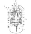
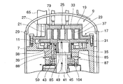
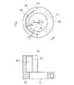
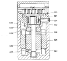
図1は、本発明にかかる密閉形スクロール圧縮機の実施形態を示す全体構成断面図であり、図2は図1の全体断面図のうちの上方の部分の拡大図である。図3は駆動軸の組付け状態の示す説明図である。図4は上バランサの説明図であり、(a)は平面図であり、(b)は(a)のC−C断面図である。 FIG. 1 is an overall cross-sectional view showing an embodiment of a hermetic scroll compressor according to the present invention, and FIG. 2 is an enlarged view of an upper portion of the overall cross-sectional view of FIG. FIG. 3 is an explanatory view showing the assembled state of the drive shaft. 4A and 4B are explanatory views of the upper balancer. FIG. 4A is a plan view, and FIG. 4B is a cross-sectional view taken along the line C-C in FIG.
図1、図2を参照して密閉形スクロール圧縮機の全体構成について説明する。図1に示すように、密閉形スクロール圧縮機1を構成する縦長の円筒形状の密閉ケース2は、湾曲形状の下ケース3と湾曲形状の上ケース5と円筒状の中ケース6とがそれぞれ溶接接合されて形成されている。
密閉ケース2内の上方寄りに、密閉ケース2内を上下に仕切るようにフレーム部材7が中ケース6の内部に取付けられている。
そして、フレーム部材7の上方にはスクロール圧縮機構部(圧縮機構部)9が配置され、下方にはスクロール圧縮機構部9を構成する旋回スクロール11に旋回運動の回転力を与えるモータ13が配置されている。さらに、密閉ケース2の底部には潤滑油が収容されるようになっていて、底部に貯留された潤滑油を汲み上げる給油ポンプ15がモータ13の下方に配置されている。
The overall configuration of the hermetic scroll compressor will be described with reference to FIGS. 1 and 2. As shown in FIG. 1, a vertically long cylindrical sealed
A
A scroll compression mechanism (compression mechanism) 9 is disposed above the
図2に示すように、スクロール圧縮機構部9は、固定スクロール17と、この固定スクロール17の下方に配置された旋回スクロール11とによって構成されている。固定スクロール17は、円板状の端板19と、この端板19の一方の面の周縁部に突設された環状壁21と、この環状壁21で囲まれた部分に該環状壁21とほぼ等しい高さに突設された固定スクロール翼23と、端板19の略中央部に設けられた吐出口25と、端板19の周縁部に設けられた吸入口27とで構成されている。そして、環状壁21の延長部分がボルト29でフレーム部材7に固定されている。
As shown in FIG. 2, the scroll compression mechanism unit 9 is composed of a fixed
一方、旋回スクロール11は、円板状の旋回スクロール11の端板31と、この端板31の一方の面に前記固定スクロール翼23と等しい高さに突設された旋回スクロール翼33と、他方の面の中央部には軸受ボス部35が突設されて構成されている。
On the other hand, the orbiting
また、旋回スクロール11の端板31に螺旋状に突設され上方向を向いた旋回スクロール翼33と、固定スクロール17の端板19に螺旋状に突設され下方向を向いた固定スクロール翼23とが噛合い、それぞれの壁の間に圧縮室37を形成している。
In addition, the
そして、固定スクロール17と旋回スクロール11との噛み合い状態を保持して旋回スクロール11を固定スクロール17に対して相対的に旋回運動させるために、旋回スクロール11の端板31とフレーム部材7との間にオルダム機構38が設けられている。
Then, in order to maintain the meshed state of the fixed
フレーム部材7には、旋回スクロール11の軸受ボス部35の軸心線に対して偏心した円筒状の旋回空間39が上下方向に貫通して設けられており、この旋回空間39の下端部分にはモータ13の駆動軸41を回転自在に支持する転がり軸受ないしはすべり軸受で構成された主軸受43が設けられている。なお、転がり軸受はコロ軸受けでも玉軸受でもよい。
The
駆動軸41の上端部には、駆動軸41の軸中心線と偏心した位置にクランク部45が形成され、該クランク部45が旋回スクロール11の軸受ボス部35に嵌入している。この軸受ボス部35がクランク部45の旋回軸受を形成している。
また、図1に示すように、駆動軸41の下端部には、サブフレーム46に支持され給油ポンプ15が接続されていて、この給油ポンプ15で潤滑油をパイプ47によって汲み上げて、駆動軸41の軸中心部を貫通して設けられた貫通油路49を介して前記クランク部45の上端から軸受ボス部35内に放出するようになっている。
A
Further, as shown in FIG. 1, an
前記モータ13は、複数の分割ステータ51がモータフレーム53の内周に沿って環状に配設された、いわゆる分割式のステータによって構成され、回転子はロータ55の内部に永久磁石が埋め込まれるいわゆるIPMモータによって構成している。そして、ロータ55は駆動軸41に取り付けられて着磁される。
The
さらに、このモータ13の巻線は、アンモニア冷媒に対して耐食性が強く信頼性の高いアルミニウム電線によって形成されている。
なお、使用される圧縮ガスはアンモニア冷媒を用いており、吐出ガス温度の上昇を抑えるためにアンモニアの液冷媒を固定スクロール17の端板19に取付けられた液インジェクション配管57から圧縮室37内に噴射するようになっている。
Furthermore, the winding of the
Note that the compressed gas used is ammonia refrigerant, and in order to suppress the rise in discharge gas temperature, the ammonia liquid refrigerant is fed into the
また、駆動軸41に対して偏心したクランク部45の回転に伴うアンバランスを打ち消すために、駆動軸41には、上から順に上バランサ59、中バランサ61、下バランサ63の3つのバランサが取り付けられていて、上バランサ59は鉄製で、中バランサ61、下バランサ63はそれぞれステンレス等の非磁性体材によって形成されている。また駆動軸中心からの重心の偏心方向が上バランサ59と中バランサ61とは同一方向となり、下バランサ63は上バランサ59と中バランサ61の位置とは駆動軸中心に関して反対側に位置している。
Further, in order to cancel the unbalance accompanying the rotation of the
さらに、前記固定スクロール17の吸入口27には、吸入管65が上ケース5を貫通して設けられ、中ケース6にはケース内の高圧ガスを吐出する吐出管67が設けられている。
Further, a
次に、前記スクロール圧縮機構部9による冷媒ガスの圧縮動作について説明する。
まず、モータ13に給電すると、駆動軸41が回転を開始する。そして、回転力が旋回スクロール11に伝えられる。
旋回スクロール11の軸受ボス部35は駆動軸41に対して、偏心して設けられたクランク部45と嵌合しており、しかもオルダム機構38によって自転が阻止されているため、この旋回スクロール11は自転の伴わない旋回運動を行う。
従って、旋回スクロール11に突設された旋回スクロール翼33も旋回運動を行い、この旋回運動に伴って、旋回スクロール翼33と固定スクロール翼23との間に形成された圧縮室37が小さくなり、吸入管65を介して吸入されたガスが圧縮されて吐出口25から吐出されて、密閉ケース2内の上方に吐出されてからフレーム部材7の周囲に形成された図示しない連通孔を通って下方側に流れて密閉ケース2内のフレーム部材7の下方の空間内に高圧ガスが貯留され、吐出管67から外部へ排出される。
Next, the refrigerant gas compression operation by the scroll compression mechanism 9 will be described.
First, when power is supplied to the
Since the bearing
Therefore, the
次に、潤滑油の供給について説明する。
下ケース3の底部に収容された潤滑油を給油ポンプ15によって汲み上げて、貫通油路49を介してクランク部45の上端から軸受ボス部35の内部に放出して、クランク部45と軸受ボス部35との摺動部を潤滑し、その後、軸受ボス部35の下方に形成された隙間85、さらにフレーム部材7に径方向に形成された横穴87から密閉ケース2内に排出され、下方の油槽に戻される。
また、隙間85からの潤滑油の一部は上バランサ59の遠心力によって縦壁88に沿って上方に案内されて、旋回シール79に向かって放出されるようになっている。そして旋回シール79の潤滑やシールに用いられる。
Next, the supply of lubricating oil will be described.
Lubricating oil stored in the bottom of the lower case 3 is pumped up by the
A part of the lubricating oil from the
この上バランサ59は、図4(a)、(b)に示すように、駆動軸41から径方向に突き出る円環部86に対して該円環部86の周縁から軸方向に伸びる半円弧状の縦壁88を有して形成されるともに、該半円弧状の内側中央部には周方向溝89が形成され、遠心力によって広がる潤滑油を周方向溝89に集めて縦壁88に沿って上方の旋回空間39内に放出するように構成されている。
As shown in FIGS. 4A and 4B, the
さらに具体的に説明すると、円環部86とその円環部86の周縁部から軸方向に突出した半円弧状の縦壁88で形成され、その縦壁88の外壁面は該円環部86の外径におよそ等しい外円弧Raで形成され、内壁面は外側よりの内円弧Rbと中央よりの内円弧Rcとから形成されている。
外円弧Raの中心Eは駆動軸中心におよそ一致させ、内円弧Rcの中心Fは、中心Eより縦壁の反対側すなわち図の右側に配置し、内円弧Rbの中心Gは、中心Eより縦壁側すなわち図の左側に配置して、内円弧Rbの先端が外円弧Raと内円弧Rcとの間で形成されるように縦壁88の円弧が形成されている。
More specifically, an
The center E of the outer arc Ra substantially coincides with the drive shaft center, the center F of the inner arc Rc is arranged on the opposite side of the vertical wall from the center E, that is, on the right side of the figure, and the center G of the inner arc Rb is from the center E. The arc of the
次に、以上のように構成された密閉形スクロール圧縮機において、図1、図3を参照して、駆動軸41回りの詳細構成、およびその組付けについて説明する。
図3に示すように、フレーム部材7は、中央部分が下方に円筒状に突出した形状を有し、該突出部分には旋回空間39が形成され、該旋回空間39の下方には連続して同心円状に主軸受43が嵌合する軸受嵌合穴100が形成されている。
軸受嵌合穴100の内径Aは旋回空間39の内径Bより大きく形成されている。
Next, in the hermetic scroll compressor configured as described above, a detailed configuration around the
As shown in FIG. 3, the
An inner diameter A of the bearing
駆動軸41には、上バランサ59と、主軸受43と、中バランサ61と、モータ13のロータ55と、下バランサ63とが、駆動軸41の下方側から挿入されて圧入または焼嵌め等によって取り付けられている。
また、主軸受43の下面部には環状の主軸受押板102が取り付けられている。主軸受押板102は、主軸受43を下から支持するようにボルト104によってフレーム部材7の下面に締結する。
また、ボルト104と共締めにて主軸受押板102の下面側に環状のモータカバー部材(カバー部材)106が取付けられている。
該モータカバー部材106の内周縁は駆動軸41近傍まで伸び、外周縁はモータ13を覆うように形成されている。なお、外周縁はロータ55の一部分を覆うものでもよい。
An
An annular main
An annular motor cover member (cover member) 106 is attached to the lower surface side of the main
The inner peripheral edge of the
モータカバー部材106を設けることで、主軸受43を経由して落下してきた潤滑油を下方に配置されるモータ13に直接降りかからないようにして、潤滑油がモータ13のロータ55によって攪拌されて、このモータ13の近傍に配置される密閉形スクロール圧縮機の吐出管67から潤滑油が圧縮ガスとともに排出されることを防止している。
モータカバー部材106は外周縁が垂下してモータ13に接触しても導電しないように樹脂等の非導電性材料によって形成されている。
By providing the
The
そして、このように駆動軸41に取り付けられた、上バランサ59と、主軸受43と、中バランサ61と、モータ13のロータ55と、下バランサ63と、主軸受押板102と、モータカバー部材106とが、予め一体に組立てられてから、前記フレーム部材7の下方から、駆動軸41の先端部のクランク部45を軸受ボス部35内に嵌合し、上バランサ59を旋回空間39内に収容し、主軸受43を軸受嵌合穴100の内周に嵌合するとともにボルト104で固定して、駆動軸41に一体に取り付けられた部品も、駆動軸41の組み付けと同時に組付ける。
The
かかる実施形態によれば、軸受嵌合穴100の内径Aを旋回空間39の内径Bより大きく形成することによって、駆動軸41に主軸受43、上バランサ59、中バランサ61、下バランサ63、さらにロータ55、主軸受押板102、モータカバー部材106を一体化した状態で、組付けが可能になるため、密閉形スクロール圧縮機の組立てが簡単化して、組立て工数が減少し生産効率が向上する。
According to this embodiment, by forming the inner diameter A of the bearing
さらに、駆動軸41を組付けた後にロータ55や各バランサ59、61、63等を焼嵌めや圧入を行うと、その焼嵌めや圧入の作業に伴って発生する熱や金属屑によって熱変形や摺動部の損傷などが生じやすいという問題があるが、駆動軸に主軸受、上バランサ、中バランサ、下バランサ、さらにモータのロータを一体化した状態で、組付けが可能になるため、これら問題が解消されて熱変形や摺動部の損傷のない密閉形スクロール圧縮機を得ることができる。
Further, when the
さらに、駆動軸41に取付けられるロータ55が永久磁石を内蔵したロータであって組付け前に着磁されていても、バランサ、特に中バランサ61、下バランサ63が非磁性体材料のステンレスによって形成されているため、中、下バランサ61、63がロータ55によって磁化されないので、駆動軸41に主軸受43、上バランサ59、中バランサ61、下バランサ63、さらにロータ55、主軸受押板102、モータカバー部材106を一体化した状態で、フレーム部材7への組付ける際に、中、下バランサ61、63が周りの部品に引き付けられることによる、組付け作業への悪影響が低減されて、安定した組立て作業ができる。
Further, even if the
また、組付け前に予め着磁することで安定した高密度の磁気を着磁することが可能になるので、モータの出力を向上することができる。 Moreover, since it becomes possible to magnetize the stable high-density magnetism by pre-magnetizing before assembly, the output of the motor can be improved.
本発明によれば、駆動軸に取付けられる上、中、下のバランスウエイト、モータのロータ、さらには軸受を、駆動軸に予め装着した状態で、密閉形圧縮機のフレーム部材に取付けることができるようなるとともに、モータのロータが永久磁石を内蔵した、いわゆるIPMモータの場合であって、組付け前に磁化される場合でも、磁化による引付力の影響を軽減して、安定した組立て作業ができるので、冷凍空調用密閉形圧縮機を始めとしてモータを内蔵したカーエアコン用圧縮機、空気圧縮機及び真空ポンプ等を含むスクロール流体機械への適用に際して有益である。 According to the present invention, the upper, middle, and lower balance weights, the motor rotor, and the bearing that are attached to the drive shaft can be attached to the frame member of the hermetic compressor in a state of being mounted on the drive shaft in advance. In addition, even in the case of a so-called IPM motor in which the rotor of the motor has a built-in permanent magnet, and magnetized before assembly, the influence of the attracting force due to magnetization is reduced and stable assembly work can be performed. Therefore, it is useful for application to a scroll fluid machine including a compressor for a car air conditioner having a built-in motor, an air compressor, a vacuum pump, and the like, including a hermetic compressor for refrigeration and air conditioning.
1 密閉形スクロール圧縮機
2 密閉ケース
7 フレーム部材
9 スクロール圧縮機構部(圧縮機構部)
11 旋回スクロール
13 モータ
17 固定スクロール
35 軸受ボス部
39 旋回空間
41 駆動軸
43 主軸受
51 ステータ
55 ロータ
59 上バランサ
61 中バランサ
63 下バランサ
88 上バランサの縦壁
89 周方向溝
100 軸受嵌合穴
106 モータカバー部材(カバー部材)
A 軸受嵌合穴の内径
B 旋回空間内径
1
9 Scroll compression mechanism (compression mechanism)
DESCRIPTION OF
A Inner diameter of bearing fitting hole B Inner diameter of turning space
Claims (5)
前記上バランサと中バランサとの間に前記駆動軸を支える主軸受を取付け、前記フレーム部材の前記旋回空間の下方に前記主軸受が嵌合する軸受嵌合穴を形成し、該軸受嵌合穴の内径を前記旋回空間の内径より大きく前記旋回空間の軸心と一致させて形成して、前記主軸受、上、中、下バランサ、モータのロータを前記駆動軸に取付けた状態で、前記軸受を前記軸受嵌合穴に取付け可能に構成し、
前記上バランサは前記駆動軸から径方向に突き出た円環部の周縁から軸方向に伸びる半円弧状の縦壁を有して形成されるともに、該半円弧状の縦壁の内側中央部には周方向溝が形成され、遠心力によって広がる潤滑油を該周方向溝に集めて前記縦壁に沿って前記旋回空間内に放出可能であり、
前記縦壁の外壁面は外円弧で形成され、前記縦壁の内壁面は外側よりの第1内円弧と中央よりの第2内円弧とから形成され、
前記外円弧の中心は前記駆動軸の中心におよそ一致させ、前記第1内円弧の中心は、前記外円弧の中心より前記縦壁の反対側に配置し、前記第2内円弧の中心は、前記外円弧の中心より前記縦壁側に配置して、前記第2内円弧の先端が前記外円弧と前記第1内円弧との間で形成されるように前記縦壁が形成されている
ことを特徴とする密閉形スクロール圧縮機。 A compression mechanism composed of a fixed scroll and a turning scroll in a sealed case, a motor for applying a rotational driving force to the turning scroll via a drive shaft, and a cylindrical shape formed on a frame member on the back side of the turning scroll An upper balancer disposed in the swivel space and attached to the drive shaft, an intermediate balancer attached to the rotating body of the drive shaft and rotor above the motor, and the drive shaft and rotor below the motor In a hermetic scroll compressor having a lower balancer attached to a rotating body,
A main bearing that supports the drive shaft is attached between the upper balancer and the middle balancer, and a bearing fitting hole for fitting the main bearing is formed below the turning space of the frame member. The inner bearing is formed to be larger than the inner diameter of the orbiting space and coincide with the axial center of the orbiting space, and the main bearing, the upper, middle, and lower balancers and the rotor of the motor are attached to the drive shaft, and the bearing Is configured to be attachable to the bearing fitting hole ,
The upper balancer is formed to have a semicircular arc-shaped vertical wall extending in the axial direction from the periphery of the annular portion protruding in the radial direction from the drive shaft, and at the inner central portion of the semicircular arc-shaped vertical wall. Is formed with a circumferential groove, the lubricating oil spreading by centrifugal force can be collected in the circumferential groove and discharged into the swirl space along the vertical wall,
The outer wall surface of the vertical wall is formed by an outer arc, and the inner wall surface of the vertical wall is formed by a first inner arc from the outside and a second inner arc from the center,
The center of the outer arc is approximately coincident with the center of the drive shaft, the center of the first inner arc is arranged on the opposite side of the vertical wall from the center of the outer arc, and the center of the second inner arc is The vertical wall is formed so that the tip of the second inner arc is formed between the outer arc and the first inner arc, arranged on the vertical wall side from the center of the outer arc. A hermetic scroll compressor characterized by the above.
前記フレーム部材の前記旋回空間の下方に前記主軸受が嵌合する軸受嵌合穴を形成し、該嵌合穴の内径を前記旋回空間の内径より大きく前記旋回空間の軸心と一致させて形成し、前記上バランサと中バランサとの間に前記駆動軸を支える主軸受を、さらに前記上、中、下バランサ、モータのロータを前記駆動軸に取付けて一体化し、その後該一体化された部品を前記軸受嵌合穴に前記軸受をフレーム部材の下方から組付ける
ことを特徴とする密閉形スクロール圧縮機の組立方法。 In a closed space formed in a compression mechanism part composed of a fixed scroll and a turning scroll in a sealed case, a motor for applying a rotational driving force to the turning scroll via a drive shaft, and a frame member on the back side of the turning scroll And an upper balancer attached to the drive shaft, an intermediate balancer attached to the drive shaft and rotor rotator above the motor, and a drive shaft and rotor rotator below the motor. A lower balancer to be mounted , and the upper balancer is formed with a semi-arc-shaped vertical wall extending in the axial direction from a peripheral edge of an annular portion protruding in a radial direction from the drive shaft. A circumferential groove is formed in an inner central portion of the vertical wall, and lubricating oil spreading by centrifugal force can be collected in the circumferential groove and discharged into the swirl space along the vertical wall, An outer wall surface of the wall is formed by an outer arc, and an inner wall surface of the vertical wall is formed by a first inner arc from the outside and a second inner arc from the center, and the center of the outer arc is at the center of the drive shaft. The center of the first inner arc is arranged on the opposite side of the vertical wall from the center of the outer arc, and the center of the second inner arc is arranged on the vertical wall side of the center of the outer arc. An assembly method of a hermetic scroll compressor in which the vertical wall is formed such that a tip of the second inner arc is formed between the outer arc and the first inner arc ,
A bearing fitting hole into which the main bearing is fitted is formed below the orbiting space of the frame member, and an inner diameter of the fitting hole is made larger than an inner diameter of the orbiting space and coincides with an axis of the orbiting space. A main bearing for supporting the drive shaft between the upper balancer and the middle balancer, and an upper, middle, lower balancer, and motor rotor mounted on the drive shaft, and then integrated. An assembly method of a hermetic scroll compressor, wherein the bearing is assembled into the bearing fitting hole from below the frame member.
Priority Applications (1)
| Application Number | Priority Date | Filing Date | Title |
|---|---|---|---|
| JP2007267231A JP5114709B2 (en) | 2007-10-12 | 2007-10-12 | Hermetic scroll compressor and its assembly method |
Applications Claiming Priority (1)
| Application Number | Priority Date | Filing Date | Title |
|---|---|---|---|
| JP2007267231A JP5114709B2 (en) | 2007-10-12 | 2007-10-12 | Hermetic scroll compressor and its assembly method |
Related Child Applications (1)
| Application Number | Title | Priority Date | Filing Date |
|---|---|---|---|
| JP2012115595A Division JP5559839B2 (en) | 2012-05-21 | 2012-05-21 | Hermetic scroll compressor |
Publications (2)
| Publication Number | Publication Date |
|---|---|
| JP2009097358A JP2009097358A (en) | 2009-05-07 |
| JP5114709B2 true JP5114709B2 (en) | 2013-01-09 |
Family
ID=40700609
Family Applications (1)
| Application Number | Title | Priority Date | Filing Date |
|---|---|---|---|
| JP2007267231A Active JP5114709B2 (en) | 2007-10-12 | 2007-10-12 | Hermetic scroll compressor and its assembly method |
Country Status (1)
| Country | Link |
|---|---|
| JP (1) | JP5114709B2 (en) |
Families Citing this family (8)
| Publication number | Priority date | Publication date | Assignee | Title |
|---|---|---|---|---|
| WO2011104879A1 (en) * | 2010-02-26 | 2011-09-01 | 株式会社 日立製作所 | Scroll compressor |
| JP5455763B2 (en) * | 2010-04-23 | 2014-03-26 | 日立アプライアンス株式会社 | Scroll compressor, refrigeration cycle equipment |
| CN103429899A (en) | 2011-03-24 | 2013-12-04 | 三洋电机株式会社 | Scroll compression device |
| CN103443463B (en) * | 2011-03-24 | 2015-12-16 | 三洋电机株式会社 | Scroll compression device |
| JP5824668B2 (en) * | 2011-03-25 | 2015-11-25 | パナソニックIpマネジメント株式会社 | Ring body holding jig and scroll compression device |
| JP2012202252A (en) * | 2011-03-24 | 2012-10-22 | Sanyo Electric Co Ltd | Scroll compression device |
| WO2018020651A1 (en) | 2016-07-29 | 2018-02-01 | 株式会社日立産機システム | Scroll-type fluid machine and method for assembling same |
| US12162357B2 (en) * | 2022-02-10 | 2024-12-10 | Schaeffler Technologies AG & Co. KG | Drive plate configuration for torque converter |
Family Cites Families (5)
| Publication number | Priority date | Publication date | Assignee | Title |
|---|---|---|---|---|
| JP4123551B2 (en) * | 1997-11-17 | 2008-07-23 | 株式会社日立製作所 | Scroll compressor |
| JP4103225B2 (en) * | 1998-06-24 | 2008-06-18 | 株式会社日本自動車部品総合研究所 | Compressor |
| JP2000097168A (en) * | 1998-09-21 | 2000-04-04 | Sanyo Electric Co Ltd | Oilless scroll fluid machine |
| JP4094504B2 (en) * | 2003-07-08 | 2008-06-04 | 株式会社デンソー | Scroll compressor |
| JP4875346B2 (en) * | 2005-11-09 | 2012-02-15 | 三菱重工業株式会社 | Scroll compressor |
-
2007
- 2007-10-12 JP JP2007267231A patent/JP5114709B2/en active Active
Also Published As
| Publication number | Publication date |
|---|---|
| JP2009097358A (en) | 2009-05-07 |
Similar Documents
| Publication | Publication Date | Title |
|---|---|---|
| JP5114709B2 (en) | Hermetic scroll compressor and its assembly method | |
| US7938630B2 (en) | Compressor | |
| US8992188B2 (en) | Revolution type compressor | |
| CN103237990B (en) | Hermetic compressor and manufacture method thereof | |
| CN105683576B (en) | Electric scroll compressor | |
| CN109642570B (en) | scroll compressor | |
| EP3567212A1 (en) | Compressor having oldham's ring | |
| JP6745913B2 (en) | Compressor | |
| JP5559839B2 (en) | Hermetic scroll compressor | |
| CN211230820U (en) | Scroll compressor having a discharge port | |
| JPH07286586A (en) | Scroll type fluid device | |
| JP6320575B2 (en) | Electric compressor | |
| JP2008082272A (en) | Fluid compressor | |
| JP5836845B2 (en) | Scroll compressor | |
| JP2006177158A (en) | Hermetic electric compressor and refrigeration cycle apparatus | |
| JP2013204476A (en) | Scroll compressor | |
| EP3217014B1 (en) | Compressor | |
| JP6598881B2 (en) | Scroll compressor | |
| JP2009074464A (en) | Compressor | |
| JP5773922B2 (en) | Scroll compressor | |
| JP2013204479A (en) | Fluid compressor | |
| JPH05133353A (en) | Scroll compressor | |
| JP2014101835A (en) | Scroll compressor | |
| JPH074369A (en) | Scroll compressor | |
| JPH0323390A (en) | Enclosed motor driven scroll compressor |
Legal Events
| Date | Code | Title | Description |
|---|---|---|---|
| A621 | Written request for application examination |
Free format text: JAPANESE INTERMEDIATE CODE: A621 Effective date: 20100917 |
|
| A131 | Notification of reasons for refusal |
Free format text: JAPANESE INTERMEDIATE CODE: A131 Effective date: 20120323 |
|
| A977 | Report on retrieval |
Free format text: JAPANESE INTERMEDIATE CODE: A971007 Effective date: 20120329 |
|
| A521 | Request for written amendment filed |
Free format text: JAPANESE INTERMEDIATE CODE: A523 Effective date: 20120521 |
|
| TRDD | Decision of grant or rejection written | ||
| A01 | Written decision to grant a patent or to grant a registration (utility model) |
Free format text: JAPANESE INTERMEDIATE CODE: A01 Effective date: 20120918 |
|
| A01 | Written decision to grant a patent or to grant a registration (utility model) |
Free format text: JAPANESE INTERMEDIATE CODE: A01 |
|
| A61 | First payment of annual fees (during grant procedure) |
Free format text: JAPANESE INTERMEDIATE CODE: A61 Effective date: 20120920 |
|
| R150 | Certificate of patent or registration of utility model |
Free format text: JAPANESE INTERMEDIATE CODE: R150 Ref document number: 5114709 Country of ref document: JP Free format text: JAPANESE INTERMEDIATE CODE: R150 |
|
| FPAY | Renewal fee payment (event date is renewal date of database) |
Free format text: PAYMENT UNTIL: 20151026 Year of fee payment: 3 |
|
| R250 | Receipt of annual fees |
Free format text: JAPANESE INTERMEDIATE CODE: R250 |
|
| R250 | Receipt of annual fees |
Free format text: JAPANESE INTERMEDIATE CODE: R250 |
|
| R250 | Receipt of annual fees |
Free format text: JAPANESE INTERMEDIATE CODE: R250 |
|
| R250 | Receipt of annual fees |
Free format text: JAPANESE INTERMEDIATE CODE: R250 |
|
| R250 | Receipt of annual fees |
Free format text: JAPANESE INTERMEDIATE CODE: R250 |
|
| R250 | Receipt of annual fees |
Free format text: JAPANESE INTERMEDIATE CODE: R250 |
|
| R250 | Receipt of annual fees |
Free format text: JAPANESE INTERMEDIATE CODE: R250 |
|
| R250 | Receipt of annual fees |
Free format text: JAPANESE INTERMEDIATE CODE: R250 |