EP3216430B1 - Intraorale vorrichtung zur einstellung des unterkiefers - Google Patents
Intraorale vorrichtung zur einstellung des unterkiefers Download PDFInfo
- Publication number
- EP3216430B1 EP3216430B1 EP17382334.5A EP17382334A EP3216430B1 EP 3216430 B1 EP3216430 B1 EP 3216430B1 EP 17382334 A EP17382334 A EP 17382334A EP 3216430 B1 EP3216430 B1 EP 3216430B1
- Authority
- EP
- European Patent Office
- Prior art keywords
- point
- patient
- mouth
- splint
- lower jaw
- Prior art date
- Legal status (The legal status is an assumption and is not a legal conclusion. Google has not performed a legal analysis and makes no representation as to the accuracy of the status listed.)
- Active
Links
- 210000004283 incisor Anatomy 0.000 claims description 81
- 230000008878 coupling Effects 0.000 claims description 6
- 238000010168 coupling process Methods 0.000 claims description 6
- 238000005859 coupling reaction Methods 0.000 claims description 6
- 230000000284 resting effect Effects 0.000 claims description 5
- 230000003068 static effect Effects 0.000 claims description 5
- 230000000903 blocking effect Effects 0.000 claims description 3
- 210000000214 mouth Anatomy 0.000 description 102
- 238000010586 diagram Methods 0.000 description 17
- 230000007246 mechanism Effects 0.000 description 15
- 210000002455 dental arch Anatomy 0.000 description 13
- 238000000034 method Methods 0.000 description 12
- 210000001847 jaw Anatomy 0.000 description 10
- 210000004400 mucous membrane Anatomy 0.000 description 10
- 238000013461 design Methods 0.000 description 9
- 238000000926 separation method Methods 0.000 description 6
- 210000003484 anatomy Anatomy 0.000 description 5
- 208000037265 diseases, disorders, signs and symptoms Diseases 0.000 description 5
- 238000006073 displacement reaction Methods 0.000 description 5
- 208000001797 obstructive sleep apnea Diseases 0.000 description 5
- 210000003800 pharynx Anatomy 0.000 description 5
- 206010041235 Snoring Diseases 0.000 description 4
- 230000008859 change Effects 0.000 description 4
- 230000004913 activation Effects 0.000 description 3
- 230000006978 adaptation Effects 0.000 description 3
- 238000004364 calculation method Methods 0.000 description 3
- 230000006378 damage Effects 0.000 description 3
- 230000007547 defect Effects 0.000 description 3
- 208000035475 disorder Diseases 0.000 description 3
- 210000004373 mandible Anatomy 0.000 description 3
- 238000004519 manufacturing process Methods 0.000 description 3
- 238000005259 measurement Methods 0.000 description 3
- 230000008569 process Effects 0.000 description 3
- 201000002859 sleep apnea Diseases 0.000 description 3
- 208000027418 Wounds and injury Diseases 0.000 description 2
- 208000008784 apnea Diseases 0.000 description 2
- 238000013459 approach Methods 0.000 description 2
- 238000013528 artificial neural network Methods 0.000 description 2
- 206010006514 bruxism Diseases 0.000 description 2
- 230000009956 central mechanism Effects 0.000 description 2
- 230000007423 decrease Effects 0.000 description 2
- 201000010099 disease Diseases 0.000 description 2
- 208000014674 injury Diseases 0.000 description 2
- 238000005304 joining Methods 0.000 description 2
- 230000000670 limiting effect Effects 0.000 description 2
- 238000013178 mathematical model Methods 0.000 description 2
- 239000002184 metal Substances 0.000 description 2
- 230000000877 morphologic effect Effects 0.000 description 2
- 230000007935 neutral effect Effects 0.000 description 2
- 230000000241 respiratory effect Effects 0.000 description 2
- 230000029058 respiratory gaseous exchange Effects 0.000 description 2
- 210000001738 temporomandibular joint Anatomy 0.000 description 2
- 241000251730 Chondrichthyes Species 0.000 description 1
- 241001391944 Commicarpus scandens Species 0.000 description 1
- 206010021079 Hypopnoea Diseases 0.000 description 1
- JEYCTXHKTXCGPB-UHFFFAOYSA-N Methaqualone Chemical compound CC1=CC=CC=C1N1C(=O)C2=CC=CC=C2N=C1C JEYCTXHKTXCGPB-UHFFFAOYSA-N 0.000 description 1
- 241000121185 Monodon monoceros Species 0.000 description 1
- 206010062519 Poor quality sleep Diseases 0.000 description 1
- NIXOWILDQLNWCW-UHFFFAOYSA-N acrylic acid group Chemical group C(C=C)(=O)O NIXOWILDQLNWCW-UHFFFAOYSA-N 0.000 description 1
- QVGXLLKOCUKJST-UHFFFAOYSA-N atomic oxygen Chemical compound [O] QVGXLLKOCUKJST-UHFFFAOYSA-N 0.000 description 1
- 230000008901 benefit Effects 0.000 description 1
- 210000000988 bone and bone Anatomy 0.000 description 1
- 230000002802 cardiorespiratory effect Effects 0.000 description 1
- 208000026106 cerebrovascular disease Diseases 0.000 description 1
- 238000004140 cleaning Methods 0.000 description 1
- 230000001143 conditioned effect Effects 0.000 description 1
- 230000007812 deficiency Effects 0.000 description 1
- 230000002950 deficient Effects 0.000 description 1
- 230000001419 dependent effect Effects 0.000 description 1
- 230000002526 effect on cardiovascular system Effects 0.000 description 1
- 230000000694 effects Effects 0.000 description 1
- 230000006870 function Effects 0.000 description 1
- 230000036541 health Effects 0.000 description 1
- 230000006872 improvement Effects 0.000 description 1
- 238000003780 insertion Methods 0.000 description 1
- 230000037431 insertion Effects 0.000 description 1
- 230000004807 localization Effects 0.000 description 1
- 210000004072 lung Anatomy 0.000 description 1
- 230000014759 maintenance of location Effects 0.000 description 1
- 239000000463 material Substances 0.000 description 1
- 210000002050 maxilla Anatomy 0.000 description 1
- 238000003801 milling Methods 0.000 description 1
- 210000003205 muscle Anatomy 0.000 description 1
- 229910052760 oxygen Inorganic materials 0.000 description 1
- 239000001301 oxygen Substances 0.000 description 1
- 230000036961 partial effect Effects 0.000 description 1
- 230000003252 repetitive effect Effects 0.000 description 1
- 208000023504 respiratory system disease Diseases 0.000 description 1
- 230000002441 reversible effect Effects 0.000 description 1
- 230000009291 secondary effect Effects 0.000 description 1
- 210000004872 soft tissue Anatomy 0.000 description 1
- 238000002560 therapeutic procedure Methods 0.000 description 1
- 230000001052 transient effect Effects 0.000 description 1
- 238000009423 ventilation Methods 0.000 description 1
- 230000000007 visual effect Effects 0.000 description 1
Images


Classifications
-
- A—HUMAN NECESSITIES
- A61—MEDICAL OR VETERINARY SCIENCE; HYGIENE
- A61F—FILTERS IMPLANTABLE INTO BLOOD VESSELS; PROSTHESES; DEVICES PROVIDING PATENCY TO, OR PREVENTING COLLAPSING OF, TUBULAR STRUCTURES OF THE BODY, e.g. STENTS; ORTHOPAEDIC, NURSING OR CONTRACEPTIVE DEVICES; FOMENTATION; TREATMENT OR PROTECTION OF EYES OR EARS; BANDAGES, DRESSINGS OR ABSORBENT PADS; FIRST-AID KITS
- A61F5/00—Orthopaedic methods or devices for non-surgical treatment of bones or joints; Nursing devices; Anti-rape devices
- A61F5/56—Devices for preventing snoring
- A61F5/566—Intra-oral devices
-
- A—HUMAN NECESSITIES
- A61—MEDICAL OR VETERINARY SCIENCE; HYGIENE
- A61C—DENTISTRY; APPARATUS OR METHODS FOR ORAL OR DENTAL HYGIENE
- A61C5/00—Filling or capping teeth
- A61C5/007—Dental splints; teeth or jaw immobilisation devices; stabilizing retainers bonded to teeth after orthodontic treatments
-
- A—HUMAN NECESSITIES
- A61—MEDICAL OR VETERINARY SCIENCE; HYGIENE
- A61C—DENTISTRY; APPARATUS OR METHODS FOR ORAL OR DENTAL HYGIENE
- A61C7/00—Orthodontics, i.e. obtaining or maintaining the desired position of teeth, e.g. by straightening, evening, regulating, separating, or by correcting malocclusions
- A61C7/08—Mouthpiece-type retainers or positioners, e.g. for both the lower and upper arch
-
- A—HUMAN NECESSITIES
- A61—MEDICAL OR VETERINARY SCIENCE; HYGIENE
- A61F—FILTERS IMPLANTABLE INTO BLOOD VESSELS; PROSTHESES; DEVICES PROVIDING PATENCY TO, OR PREVENTING COLLAPSING OF, TUBULAR STRUCTURES OF THE BODY, e.g. STENTS; ORTHOPAEDIC, NURSING OR CONTRACEPTIVE DEVICES; FOMENTATION; TREATMENT OR PROTECTION OF EYES OR EARS; BANDAGES, DRESSINGS OR ABSORBENT PADS; FIRST-AID KITS
- A61F5/00—Orthopaedic methods or devices for non-surgical treatment of bones or joints; Nursing devices; Anti-rape devices
- A61F5/56—Devices for preventing snoring
-
- A—HUMAN NECESSITIES
- A61—MEDICAL OR VETERINARY SCIENCE; HYGIENE
- A61C—DENTISTRY; APPARATUS OR METHODS FOR ORAL OR DENTAL HYGIENE
- A61C19/00—Dental auxiliary appliances
- A61C19/04—Measuring instruments specially adapted for dentistry
- A61C19/05—Measuring instruments specially adapted for dentistry for determining occlusion
-
- A—HUMAN NECESSITIES
- A61—MEDICAL OR VETERINARY SCIENCE; HYGIENE
- A61C—DENTISTRY; APPARATUS OR METHODS FOR ORAL OR DENTAL HYGIENE
- A61C7/00—Orthodontics, i.e. obtaining or maintaining the desired position of teeth, e.g. by straightening, evening, regulating, separating, or by correcting malocclusions
-
- A—HUMAN NECESSITIES
- A61—MEDICAL OR VETERINARY SCIENCE; HYGIENE
- A61F—FILTERS IMPLANTABLE INTO BLOOD VESSELS; PROSTHESES; DEVICES PROVIDING PATENCY TO, OR PREVENTING COLLAPSING OF, TUBULAR STRUCTURES OF THE BODY, e.g. STENTS; ORTHOPAEDIC, NURSING OR CONTRACEPTIVE DEVICES; FOMENTATION; TREATMENT OR PROTECTION OF EYES OR EARS; BANDAGES, DRESSINGS OR ABSORBENT PADS; FIRST-AID KITS
- A61F5/00—Orthopaedic methods or devices for non-surgical treatment of bones or joints; Nursing devices; Anti-rape devices
- A61F5/56—Devices for preventing snoring
- A61F2005/563—Anti-bruxisme
Definitions
- the present invention concerns an intra-oral device for mandibular adjustment, applicable in the treatment of sleep apnea, respiratory disorders and bruxism, as a sports mouth guard and as a positioner without set up (a device used to position the dental arches in an ideal position).
- the device includes an upper splint adapted to a patient's upper jaw and a lower splint adapted to a patient's lower jaw, wherein the upper splint and the lower splint are related to allow the positioning, in a customised and controlled way for each patient, of the lower jaw in different positions of protrusion advance, both when the patient's mouth is closed, when the mouth is open and during the process of opening and closing of the patient's mouth.
- the device of the invention has the particularity of being totally customised for each patient, since splints are designed according to the patient's anatomy, oral cavity morphology, required mandibular protrusive advancement and the sequence, in millimetres, of the mandibular protrusive advancement that is desired, thus changing a lower splint for another lower splint with another different mandibular protrusive advancement.
- the device of the invention falls within the technical sector of odontology for the design and manufacture of orthodontic devices, and more specifically for that of intra-oral dental appliances for the treatment of snoring, sleep apnea-hypopnea syndrome, as well as other disorders such as bruxism, breathing disorders, as a sports mouth guard, and a positioner without set-up.
- SAHS Sleep apnea-hypopnea syndrome
- the number of occlusions can vary from one to hundreds of times, depending on the severity of the disease, which causes that, over time, cardiovascular, cardiorespiratory, and cerebrovascular diseases, and neuropsychiatric disorders can be caused. These are the secondary effects due to oxygen desaturation, transient and subconscious awakenings caused by SAHS.
- sleep apnea-hypopnea syndrome has a serious impact on patients' quality of life due to lack of sleep and/or deep sleep at night.
- intra-oral devices intended to act on a patient to reduce sleep apnea are known in the market. These intra-oral devices, known as MAD, advance the lower jaw relative to the upper jaw, opening a larger space in the back of the oral cavity and thereby facilitating the passage of air from the pharynx and also into the pharynx.
- Intra-oral devices generally comprise a dental appliance made to measure for the patient with an upper splint intended to be placed in the upper dental arch of the upper jaw and a lower splint intended to be placed in the lower dental arch of the lower jaw.
- these two splints may be adhered to each other, called a monobloc device or apparatus, and in a second embodiment, the two splints comprise two independent elements.
- the intra-oral device of this second embodiment is the most commonly used at present.
- Devices with separate parts typically connect the upper splint and the lower splint with mechanisms that are positioned and tensioned so as to maintain the lower splint forward relative to the upper splint, in comparison to a rest state in which both splints would be in a neutral position, one above the other, according to the normal bite of the patient.
- mandibular advancement mechanisms are known in the state of the art.
- central metal mechanisms composed of a lower part and an upper part, respectively connected to the lower splint and to the upper splint of the dental device.
- the lower splint and the upper splint are interconnected by an adjustable mechanism in the longitudinal direction, for example by means of an adjustable threaded connection, which allows adjusting the position of the lower splint with respect to the upper splint.
- An example of this type of mandibular advancement mechanism is the patent with publication number DE 103 41 260 .
- Another device with mandibular advancement mechanism is the Spanish patent with publication number ES 2 365 003 property of the same holder as the present invention.
- This Spanish patent includes an adjustable central mechanism that adjusts the patient's mandibular protrusion.
- said adjustable central mechanism has a system that allows the patient to perform laterality, which are relative displacements in both directions of a transverse direction. In this way, the patient feels more comfortable and avoids problems in the dental arches.
- This device described in the Spanish patent, allows opening and a simultaneous mandibular advancement during said opening.
- Another type of mechanism is one that combines lateral metallic and acrylic elements. It comprises a device composed of a lower splint and an upper splint, which are connected laterally by upper and lower flanges, together with an adjustable screw in each of the upper flanges, which at the time of adjustment applies a force against the flanges causing the jaw to move forward.
- Somnomed, Somnodent which corresponds to that disclosed by the patent with publication number US 6604527 and also in other products such as the dorsal application Dynflex, and that of Dr. Nordstrom, NorSor II produced by Murdock labs.
- devices comprising mandibular advancement mechanisms made of plastic material, generally consisting of one or more plastic ties that link the lower splint and the upper splint of the device.
- the mechanism is formed by a single tie arranged like a connecting rod in the front area of the upper and lower splints, interconnecting both so that the jaw is advanced with respect to the upper jaw.
- the mechanism consists of two ties, one on either side of the device, the ends of which are connected to one side of the lower splint and to the same side of the upper splint.
- An example of this mandibular advancement mechanism is disclosed in the patent with publication No. US 2012073582 A1 belonging to the Silent Nit device, or in the Narval device produced by Resmed as disclosed in the patent with publication No. 7146982 .
- a single tie is provided, the ends of which are connected to two opposite sides of the lower splint and whose central area is supported on the front of the upper splint of the device.
- devices provided with plastic mandibular advancement mechanisms are more comfortable for the patient because they have some lateral and/or longitudinal flexibility, which allows the patient to move the jaw slightly when they are asleep, while the jaw is kept correctly advanced with respect to the upper jaw, achieving greater comfort and adaptation in the patient.
- This device is digitally designed and manufactured by milling, which provides advancement precise increments to facilitate the calibration of mandibular advancement without the need for an adjustable mechanism or tie exchanges. Digital manufacturing also avoids production errors.
- This device is described in the patent with publication number US 2016/0184129 , and is used by Microdental's Micro2.
- a mandibular repositioning appliance including a first splint with a first connecting member comprising a forward facing axis for protrusive positioning of a mandible: a second splint with a second connecting member; and a link arm coupled to first connecting member for pivotal movement about said axis, the link arm extending transverse to said axis to engage with said second connecting member in a slidable coupling that allows a range of relative movement in said transverse dimension; wherein protrusive positioning of the mandible is provided by relative positioning of the link arm along said axis; and wherein said members are attached to lateral legs of said splints such that the forward facing axis is substantially aligned with either side of the mid-sagittal plane in use in a patient.
- the invention proposes an intra-oral mandibular adjustment device, comprising an upper splint configured to fit a patient's upper jaw and a lower splint configured to conform to the lower jaw of said patient, wherein the upper splint and the lower splint are related so as to be able to place the lower jaw in different positions when the patient makes use of the device of the invention.
- the intra-oral device comprises two followers arranged on two opposite sides, and housings delimited by edges comprising contact surfaces, where the followers are located on the opposite sides of the upper splint or lower splint, and where the housings are located in extensions that are interdependent to the lower splint or upper splint.
- the device could include a single follower and a single contact surface.
- the extensions may comprise a structure without the housings, so that in these cases the contact surface comprises one of the edges of said extensions.
- the followers are fitted into the housings, where the followers are in tangential contact with the contact surfaces during use of the device of the invention.
- These contact surfaces in combination with the followers when in tangential contact with said contact surfaces constitute means for guiding and positioning of the lower jaw if the patient opens or closes the mouth.
- the contact surfaces in combination with the followers when in tangential contact with said contact surfaces constitute a means of static positioning of the lower jaw.
- the followers of the intra-oral device comprise lugs protruding outwardly with respect to opposite outer faces of the lower splint or upper splint, where the followers are located below or above a plane delimiting a lower or upper surface of the upper splint or lower splint, respectively, all depending on whether the contact surfaces and followers are located on the lower splint or the upper splint.
- the upper splint and the lower splint are related by a coupling with lateral gaps, wherein said lateral gaps are delimited between the extensions, and portions of the opposite outer faces, and wherein said lateral gaps allow controlled lateral mobility in a transverse direction of the lower jaw towards two opposite sides of the lower jaw when the patient makes use of the device of the invention.
- the extensions include inner faces and outer faces opposite the inner faces, wherein said outer faces comprise dome-shaped surfaces on which internal mucous membranes of the patient's cheeks can rest to prevent said internal mucous membranes from entering into the housings and thereby preventing injury to the patient, possible pinching of the mucous membranes in particular.
- the followers of the intra-oral device include ends located within the housings without protruding outwardly with respect to the outer faces of the extensions. This feature also helps to prevent possible damage to the mucous membranes of the cheeks.
- Each housing comprises a closed contour, which is formed by an upper stop, a lower stop, the contact surface on which the follower contacts, and an additional surface facing, and opposite said contact surface.
- the upper stop can constitute an element that delimits the maximum opening of the patient's mouth.
- the additional surface constitutes a stop to limit a possible inadequate mandibular advancement of the patient.
- the contact surfaces of the housings comprise a profile with arched trajectory.
- the contact surfaces will be designed in accordance to the patient's parameters, which will define a trajectory to follow.
- the numerous possible trajectories of the contact surface are defined by a characteristic equation which will be described below in the section of the embodiment example of the invention, so that, in order to determine the trajectory of the contact surface, the previously known positions of a first point of the lower incisors of the lower jaw when said first point is located in a position with the mouth closed (position in contact with the occlusal plane) and in a position with the mouth open are related.
- An initial tangential contact of the follower with the contact surface is also taken as known datum when the patient has the mouth closed.
- the followers are fitted into the housings in a position in which said followers are in contact simultaneously with the contact surfaces, with the upper stops and with the lower stops of the housings maintaining a static position of the lower splint with respect to the upper splint, wherein the thus configured intra-oral device maintains the lower jaw in a resting position with the patient's closed mouth blocking the mobility of the patient's lower jaw.
- the two lateral contact surfaces are contained in two asymmetrical planes, where said contact surfaces are defined by different curves.
- This embodiment of the invention is applicable to those patients who have a deformity or defect in the upper jaw, lower jaw, or even in the mandibular joint, so that in this situation when these patients open his/her mouths, there is an asymmetric opening where the variation of the separation between the upper and lower molars of one side (right) of the mouth is different from the variation of the separation between the upper and lower molars of the other side (left) of the patient's mouth.
- the device of the invention has the purpose of solving the problems caused by snoring and apneas due to a poor passage of air through the pharynx, based essentially on causing the mandibular advancement in a controlled way, so that the lower jaw is forced to move progressively forward, pulling with it the tongue and soft tissues that can posturally block the pharynx. According to the mandibular advancement required for each patient, the lower splints will be exchanged.
- the device of the invention has the particularity of being totally customised for each patient, since the structure of the splints is designed according to the patient's anatomy, the morphology of the oral cavity, the required mandibular advancement and the sequence in millimetres of the mandibular advancement that is desired in order to go from one lower splint to another lower splint, thus varying the trajectory of the contact surface.
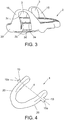
- the intra-oral mandibular adjustment device comprises an arch-shaped upper splint (1) configured to be adapted and fixed to an upper jaw (16) of a patient and an arch-shaped lower splint (2) configured to be adapted and fixed to a lower jaw (9) of the patient.
- the upper splint (1) and the lower splint (2) are related to each other to be able to place the lower jaw (9) in different controlled positions when the patient wearing the device of the invention has the mouth in the closed position, in the open position, and also during the movement of opening and closing of the mouth.
- the intra-oral device of the invention allows to place the lower jaw (9) with the mouth closed on an initial neutral position without retrusion and without protrusion advancement, while in other embodiments the intra-oral device allows to place the lower jaw (9) in different positions of mandibular advancement with the mouth closed.
- the intra-oral device during the opening of the patient's mouth, the intra-oral device generates intermediate positions in protrusion advancement of the lower jaw (9) which are more advanced positions than the initial position with the mouth closed. Including up to the maximum jaw opening that the device allows, the lower jaw (9) assumes a final position that is also a more advanced position than the initial position with the mouth closed and than all the intermediate positions that the lower jaw (9) runs along during its opening.
- the intra-oral device of the invention maintains the initial mandibular advancement which is taken as an initial reference with the mouth closed, in all the intermediate positions and also the corresponding final position with maximum jaw opening that the device allow, i.e. in this particular case the intra-oral device of the invention maintains the initial mandibular advancement constant during the opening of the mouth and also when it reaches the final position corresponding with the maximum jaw opening that the device allows.
- the intra-oral device shown in the figures comprises a pair of followers (19) arranged in a transverse direction (4) outside the molars of the patient's teeth, and at least one pair of contact surfaces (3a) also arranged outside the molars of the patient's teeth, where the followers (19) are configured to contact on said contact surfaces (3a) through a tangential contact.
- the device of the invention comprises a single follower (19) and a single contact surface (3a).
- the followers (19) are located on the upper splint (1) and the contact surfaces (3a) are located on the lower splint (2), although, it is also possible to do the reverse, i.e., that the followers (19) are located on the lower splint (2) and the contact surfaces (3a) are located on the upper splint (1).
- the intra-oral device comprises the two contact surfaces (3a) located on the lower splint (2), and two followers (19) located on the upper splint (1), wherein the followers (19) and contact surfaces (3a) are in correspondence with the molars of the upper jaw (16) and the molars of the lower jaw (9) of the patient, respectively.
- the two followers (19) of the upper splint (1) are configured to be fitted into housings (3), wherein said housings (3) are located in extensions (15) interdependent to the lower splint (2), and where said housings (3) are delimited by edges that comprise the contact surfaces (3a) on which the followers (19) contact tangentially.
- the lower splint (2) moves guided by the followers (19) of the upper splint (1) through the contact surfaces (3a) of the lower splint (2), where said followers (19) serve as fixed guiding elements on which the lower splint (2) is guided by tangential contact on the contact surfaces (3a) of the lower splint (2).
- each housing (3) of the lower splint (2) comprises a closed contour that consists of an upper stop (3c), a lower stop (3d) and two opposite faced guide sections called contact surface (3a) and an additional surface (3b), wherein said opposite guide sections of the contour of the housing (3) have arched profile trajectories.
- any position of the lower splint (2) depends on the tangential contact of the pair of followers (19) on the guide contact surfaces (3a) that define part of the contour of the housings (3) of the lower splint (2).
- the two contact surfaces (3a) and the two followers (19) are configured so that a patient with the mouth closed in an initial resting position and when said patient is wearing the device of the invention on the inside of his/her mouth, his/her lower jaw (9) is placed, for example in a position of protrusion advancement, and that in any open mouth position of the user, the lower jaw (9) is placed in a position of protrusion advancement further forward than the initial position of protrusion advancement with the mouth closed, although it is also possible to maintain the initial position of protrusion advancement when the patient opens his/her mouth, as has already been referred to above.
- the followers (19) of the upper splint (1) comprise lugs protruding outwardly with respect to opposite outer faces (20) of the lower splint (2), wherein the followers (19) are located below a plane (17) that delimits a lower surface of the upper splint (1).
- the lower splint (2) also includes opposite outer faces (20'). These opposite outer faces (20, 20') comprise outer side surfaces of the upper splint (1) and the lower splint (2).
- the followers (19) will be located above a plane, which delimits an upper surface of the lower splint.
- the coupling between the upper splint (1) and the lower splint (2) is a coupling with lateral gaps (18) that allow a controlled mobility of the lower jaw (9) towards both sides of the lower jaw (9) in a transverse direction to achieve greater comfort for the patient wearing the device of the invention within his/her mouth.
- the lateral gaps (18) are delimited between inner faces (15a) of the extensions (15) where the housings (3) are located, and some portions of the opposite outer faces (20) of the upper splint (1).
- the extensions (15) include other outer faces (15b) opposite to the inner faces (15a), wherein said outer faces (15b) can contact with the internal mucous membranes of the cheeks of the patient, and where said outer faces (15b) comprise dome-shaped surfaces to better adapt to the patient's internal mucous membranes of the cheeks and more effectively prevent possible pinching of the internal mucous membranes of the cheeks in the areas of coupling of the followers (19) within the housings (3).
- These dome-shaped surfaces of the outer faces (15b) are configured taking into account, since they are customised, the shape of the dental arch of the patient.
- the followers (19) of the upper splint (1) are located in a fixed position, while the contact surfaces (3a) of the lower splint (2) are located at a distance that may vary.
- an upper splint (1) and a set of several lower splints (2) are taken ( Figure 5 ), wherein the positioning of the extensions (15) and contact surfaces (3a) of the lower splints (2) varies from lower splints (2) with respect to other lower splints (2).
- a particular lower splint (2) is taken maintaining a fixed positioning of the contact surfaces (3a), and a set of several upper splints (1) where the positioning of the followers (19) varies from the upper splints (1) with respect to other upper splints (1).
- the followers (19) of the upper splint (1) are fixed into the housings (3) of the lower splint (2), at the same time as said followers (19) are also in simultaneous contact with the contact surfaces (3a), the upper stops (3c) and lower stops (3d) of the housings (3) maintaining a static position of the lower splint (2) in the position desired with respect to the upper splint (1).
- the device keeps the lower jaw (9) in a resting position with the patient's mouth closed blocking the mobility of the lower jaw (9).
- Figure 7a shows a movement of the lower jaw, taking as a reference a point (p) of the central lower incisors (7) which passes from an initial position "ai" when the patient has his/her mouth closed with a determined percentage of protrusion advancement, up to a final position "bi" when the patient has his/her mouth open, also with a protrusion advancement further advanced than the initial position "ai" of protrusion with the mouth closed.
- the end limits of the upper straight line (5c) correspond to a point (c) of maximum retrusion and a point (d) of maximum protrusion of the lower jaw (9) when the mouth is closed, where said end limits correspond to the end positions of the point (p) of the lower incisors (7) of the lower jaw (9).
- the initial position "ai" of the point (p) of the lower incisors (7) is located in an area of the upper straight line (5c), and the final position "bi" of the point (p) of the lower incisors (7) is located on an area of the forward curve (5a).
- initial “ai” and final “bi” the patient first moves his/her lower jaw (9) with the mouth closed until placing the point (p) of the incisors in one of the various initial positions "ai” with a determined degree or percentage of protrusion, (for example as shown in Figure 9 : (25%, 50%, 60%, 75%) and subsequently, with the initial position "ai” as reference, the patient opens his/her mouth until the point (p) of the incisors reaches the final position "bi" located on the forward curved line (5a), where the "b” final position is a position of protrusion advancement further forward than the initial position "ai".
- the path from point (p) of the lower incisors (7) from the initial position "ai” to the final position "bi”, is a path defined by a trailing edge (8), where it is possible to maintain the initial position of the mandibular protrusion advancement, and where said trailing edge (8) is performed during the mobility of the lower splint (2) dragged by the lower jaw (9), which moves following the trajectory of tangential contact of each contact surface (3a) on the follower (19).
- the increase in the percentage of protrusion advancement of the lower jaw (9) with the mouth closed referenced with positions "ai" along the upper straight line (5c) is inversely proportional to the length of the trailing edge (8) which corresponds to the distance between each initial position "ai" of the point (p) of the lower incisors (7) which it takes along the upper straight line (5 c) and each final position "bi" of the point (p) of the lower incisors (7) which it takes along the forward curved line (5a) of the Posselt diagram (5).
- the initial position "ai" would correspond to a percentage of protrusion advancement of 50%.
- the percentage will decline, and as we approach the point (d) the percentage corresponding to the end of maximum protrusion will increase.
- a first angle " ⁇ " is also measured to define the angular space between the plane of occlusion (6) where the upper straight line (5c) of the Posselt diagram (5) is contained and a first inclined straight line (10) that connects the centre of the condyle (9a) of the lower jaw (9) with the point (p) of the lower incisors (7).
- An angle " ⁇ ” is defined, which is an angular amplitude that corresponds to the rotation of the lower jaw (9) when the point (p) of the lower incisors (7) passes from the "ai" position to the "bi” position.
- the condyle (9a) takes a first referenced position with the point "ac"
- the condyle (9a) takes a second position referenced with the point "bc” which is in a position further forward and below the point "ac”; in such a way that joining the point "ac” and the point "bc” a second inclined straight line (11) is obtained.
- a second angle " ⁇ " is defined, which symbolises the direction in which the condyle (9a) will move during the opening of the mouth in a movement of protrusion advancement when the lower jaw (9) passes from the initial position "ai" to the final position "bi".
- the capacity of advancement of the lower jaw (9) is represented from the protrusion and retrusion data provided by the doctor and located on the upper straight line (5c), which correspond to the different initial positions "ai" of the point (p) of the lower incisors (7).
- a curved line is drawn that simplifies the forward curved line (5a) and rear curved line (5b), since there is really only one curved line (distance between the condyle (9a) and the point (p) of the lower incisors (7) of the lower jaw (9)) centred on a point of the second inclined line (11), simplifying the displacement of the condyle (9a) and passing through the point (c) of maximum retrusion (rear curved line (5b)) and the point (d) of maximum protrusion (forward curved line (5a)).
- the length of the rear curved line (5b) is around 20-25 mm of linear separation between an upper incisor (12) of the upper jaw (16) and the lower incisor (7) of the lower jaw (9), i.e. when the patient opens the mouth along the rear curved line (5b), a pure rotation is produced during the opening of the lower jaw (9) measured as a straight line between the lower incisors (7) and upper incisors (12) which reaches 20-25 mm.
- the forward curved line (5a) is limited according to the data input for "maximum opening" of the patient's mouth and, therefore, of the lower jaw (9).
- Figure 10 shows "X” and "Y” related distances measured in perpendicular directions with reference to a point of origin of the upper incisor (12) of the upper jaw (16). Specifically, they are distances measured between said point of origin and different positions that the followers (19) of the upper splint (1) may have, which are in contact with the contact surfaces (3a) of the lower splint.
- This point of origin can be taken on an edge of the upper incisor (12) and also in other parts of said upper incisor (12). It could even be taken as a point of origin located on the upper splint (1) that may be in contact with the upper incisor (12).
- the lower jaw (9) is a single one-piece bone, it allows to directly obtain trailing edges (8') from the chin of the lower jaw (9) through different forms represented in Figures 7b , 7c and 8 .
- the first segment “MDi” is the distance between a position of protrusion advancement of the lower jaw (9) with reference to the initial position "ai” of the point (p) of the lower incisors (7) and the centre of the condyle (9a);
- the second segment “MDm” is the distance between the same advancement position of the lower jaw (9), but with reference to an initial position "ai"' of the point (p') of the chin;
- the third segment is the distance between the positions of the points (p) and (p') of the lower incisors (7) and chin when they are taking their initial positions "ai” and "ai”', respectively.
- the doctor decides where to place a first model of lower splint (2) with specific contact surface (3a), which delimits part of the contour of the housing (3); for example 60% of the total advancement measured from the point (c) of maximum retrusion ( Figure 8 ); and therefore, the result is one of the initial positions "ai" represented (60%) of the point (p) of the lower incisors (7) with the mouth of the patient closed.
- This initial position (ai) will be located on the upper straight line (5c) of advancement of the Posselt diagram (5) and the final position "bi" of the point (p) of the lower incisors (7), where the mouth at the maximum opening will be located on the forward curved line (5a) of the Posselt diagram (5).
- the result is that the initial position "ai' " of advancement of the point (p') of the symphysis menti with the mouth of the patient closed will be located on the upper straight line (5c') of advancement of the Posselt diagram (5') and a position "bi' " of the point (p') of the symphysis menti, where the mouth at the maximum opening will be located in the forward curved line (5a') of the Posselt diagram (5').
- the final position "bi" of the point (p') of the symphysis menti depends on the mobility capacity of each patient, but as a minimum it is required to be in the same vertical as the initial position "ai' " of said point (p') when on the forward curved line (5a') of the Posselt diagram (5'). Therefore, the device of the invention does not generate a retrusion of the lower jaw (9), and also, obviously, no retrusion of the chin during opening of the mouth.
- the final position "bi" of the point (p) of the lower incisors (7) of the lower jaw (9) is calculated from the final position "bi' " of the point (p') of the chin.
- the trailing edge (8') delimited between the “ai' ", "bi' “ positions of the point (p') of the chin is the curve by which it is decided to move the centre of the symphysis menti so that it does not retract and, in the case of the movement capacity of the lower jaw (9), it can even be advanced.
- the trailing edge (8) is delimited between the positions "ai", "bi” of the point (p) of the lower incisors (7) of the lower jaw (9).
- the trailing edge (8) which traverses the point (p) of the lower incisors (7) from the initial position "ai” to the final position "bi"
- the trailing edge (8') which traverses the point (p') of the symphysis menti from the initial position "ai' " to the final position "bi' ", are related to the contact surface (3a) of the lower splint (2) in the following way, according to Figures 7a , 7b , 7c , and 10 .
- any reference point can be taken from both the lower jaw (9) and the upper jaw (16), as any other cranial reference point.
- Other planes as a reference can also be taken such as the Frankfurt plane, Silla-Nasion plane and ENA-ENP plane. Other graphical and mathematical methodologies could also be used.
- the device of the invention is manufactured by CAD/CAM, wherein the various lower splints (2) are designed to increase the degree of advancement progressively to advance the lower mandible (2) millimetrically with the change of splints.
- the linkage between the two splints: lower (1), upper (2), allows to perform a movement of opening and graduated advancement by means of the relative displacement of the contact surface (3a) of contact with respect to the follower (19), so that each contact surface (3a) of the upper splint reproduces a movement according to said contact surface (3a) by contact with the fixed element called the follower (19).
- Each device of the invention has several lower splints (2) with two contact surfaces (3a) each, and the upper splint (1) with the two followers (19), wherein said contact surfaces (3a) change their shape, size and position according to a morphological study of the patient and various input data provided by the doctor such as: maximum opening of the patient's mouth, degree of mandibular advancement, degree of laterality and activation of the series of different contact surfaces (3a).
- the position, size and shape of the followers (19) can also be changed.
- the different profiles of the contact surfaces (3a) are optimised for the patient's mandibular movement for each of the lower splints (2), allowing greater comfort, total freedom of movement and preventing the retrusion of the lower jaw (9). That is, each patient will have unique input data that will result in an individual device adapted to his/her anatomical characteristics.
- the method for creating the sequence of splints comprises a succession of steps to be taken to obtain the different devices to achieve different mandibular advancements.
- the profiles of the contact surface sequence (3a) are calculated with a mathematical model from a series of data that doctors measure in patients and from an anatomic-cranial study.
- the doctors' data are:
- the neural network will allow the continuous improvement of the device as the number of patients treated increases, so that the treatment of the future patients will start from a learning process that will allow to carry out adjustments on the device that will be able to increase, more and more, the efficiency and benefit of the therapy on the health of patients.
- an intra-oral device model is constructed which represents, for each patient, the curves of forward and trailing contact movements. These curves limit the trajectory that the jaw will make when the device of the invention is used, so that an opening movement with gradual protrusive advancement has been studied. From this curve and the points of the trajectory followed by the condyle (9a) through the joint cavity the profile of the contact surface (3a) required is obtained.
- the opening achievable with the device of the invention is limited to a certain value because there may be patients in whom the upper airway section decreases as a consequence of the negative effect that the hyoid has on said section.
- the new curves of opening movements with protrusive advancement are calculated which will give rise to the new splints.
- the process continues until the maximum advancement permitted by the intra-oral device and the sequence of splints is generated with the step given, which will allow to re-adapt the treatment of the patient should he/she need more mandibular advancement.
- a treatment for the patient is formed by a set of splints with different contact surfaces (3a) that adapt to the patient's functional need at different points of advancement.
- the exchanging from one to another splint of the intra-oral device can be customised as directed by the doctor.
- each contact surface (3a) is individually and independently designed to control the advancement, degree of laterality and the possible three-dimensional rotations of the jaw.
- the intra-oral device consists of two splints (1, 2) that will be manufactured from the digitisation of the impressions of both the patients' dental arches. From the set of designs of possible splints, the contact surface (3a) has been developed which, in at least one embodiment of the invention, has the upper stop (3c) which prevents opening in the case that the theoretical limit of the contour/trailing curves of the Posselt diagram is exceeded.
- each extension (15), where the housing (3) is located includes the outer face (15b) having a dome-shaped surface which acts as a resting surface for the mucous membranes of the inner face of the patient's cheek, preventing said mucous membranes from entering into the housing (3) through which the follower (19) can be displaced.
- the additional surface (3b) also has the function of side stop in case the patient performs mandibular advancement movements, where the follower (19) will contact with said additional surface (3b).
- the two lateral contact surfaces (3a) are contained in two symmetrical planes, wherein the device of the invention comprised in this embodiment is applicable to patients who, in principle, do not have deformities or defects in the upper jaw, lower jaw or mandibular joint, so that the opening of the mouth in these patients is normal without there being any asymmetries on either side of the mouth during opening.
- the two lateral contact surfaces (3a) are contained in two asymmetrical planes, wherein said contact surfaces (3a) are defined by different curves.
- This embodiment of the invention is applicable to those patients who have a deformity or defect in the upper jaw, lower jaw, or even in the mandibular joint, so that in this situation when these patients open his/her mouths, it is an asymmetric opening where the variation of the separation between the upper and lower molars of one side of the mouth is different from the variation of the separation between the upper and lower molars of the other side of the patient's mouth, so that the device of this embodiment is capable of respecting and maintaining the normal opening of the patient's mouth without causing tensions, maintaining said asymmetrical variation on both sides of the mouth during opening.
- the mandibular rotation made by these patients with the design solution of the left and right side of the two contact surfaces (3a) is a unique design for each protrusion position according to the mandibular movement of the patient.
- the curve of the trajectory of the curve of each contact surface (3a) has the ideal trajectory to reproduce the optimum mandibular trajectory (opening with advancement) of the Posselt diagram; it being also noted that the contact surface (3a) may have any design while maintaining tangential contact with the corresponding follower (19).
- the device of the invention has the following characteristics to adapt it to the dental arch of each patient:
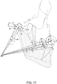
- Figures 11 to 16 show how the "ICR” (instantaneous centre of rotation) methodology is carried out and also the numerous trajectories possible of the contact surface (3a) which is defined by a curve according to an equation, which is described below.
- the points "al", "bl" of the contact surface (3a) of the extension (15) can be determined from the movement that the follower (19) will have, which will move interdependently to the lower jaw (9).
- Each contact (3a) surface can also be incorporated into a fin-shaped extension (15) like the one shown in Figure 6 , wherein said contact surface (3a) is part of an outside edge that defines the fin-shaped extension (15).
- an initial point "al" of the contact surface (3a) is taken as a basis, which corresponds to the tangential contact of the follower (19) on the contact surface (3a); where said initial point "al” corresponds to a closed position of the patient's mouth in which the point (p) of the lower incisors (7) of the lower jaw (9) is located in the initial position "ai” in coincidence with the upper line (5c) of the Posselt diagram (5).
- the position of the point (p) of the incisors will change along the contact curve (8) and as a result the centre of the condyle (9a) will also change position; for example from an initial position "ac” with the mouth closed to a final position "bc" with the mouth open.
- the final position "bi" of the point "p" of the incisors with the mouth open can be any of the forward curve line (5a) that meets the condition of opening with advancement or that no retrusion is produced.
- an advancement "s" of the condyle (9a) is calculated for each data of position "ai", “bi” of the point (p) of the lower incisors (7), unlike the device of the Somnodent patent ( US 6604527 ), wherein the displacement of the condyle is not taken into account for the calculation.
- the angle " ⁇ " is a known fact because it is previously measured with an x-ray scanner, etc.
- Said point “bl” of the contact surface (3a) can also be calculated from the intersection in the "ICR” point of two straight lines “Lc” and “Li” which are perpendicular, respectively to two lines: a first line which links the positions “ai", “bi” of the point (p) of the lower incisors with the mouth closed and open; and a second line linking the positions "ac", "bc” from the centre of the condyle (9a) that also correspond with the mouth closed and with the mouth open.
- the two straight lines “Lc” and “Li” are linked to a central points "ci", "cc" of the first and second line, respectively; all as shown in Figures 12 and 12a .
- x ICR x cc + L c ⁇ cos ⁇ 2 ′
- y ICR y cc + L c ⁇ sin ⁇ 2 ′
- y cc + L c ⁇ sin ⁇ 2 ′ y ci + L i ⁇ sin ⁇ i 2 ′ L c and L i are obtained wherein:
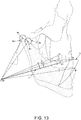
- a way to calculate the contact surface (3a) in the upper splint (1) mounted on the upper jaw (16) of the patient begins with, for example, a follower (19) having a circular section and that obviously will contact on the contact surface (3a) during use of the device of the invention, so that the references that are indicated in Figures 14a and 14b relate to the following elements.
- r radius of the follower (19).
- ⁇ ai Angle which will begin from the contact surface (3a) which corresponds to the initial position (ai) of the point (p) of the lower incisors (7) of the lower jaw (9); this angle having a value between 0 and 90°.
- ⁇ bi Angle which will reach the contact surface (3a) up to a position which corresponds to the final position (bi) of the point (p) of the lower incisors (7) of the lower jaw (9); this angle having a value between 0 and 90°.
- a 1 ' known precise location of the follower (19) as being input data.
- a 1 corresponding lower point with the tangential contact of the follower (19) and contact surface (3a).
- b 1 ' Reference point corresponding to another area of tangential contact of the follower (19) and contact surface (3a).
- Figures 15a and 15b are two different embodiments of two curved trajectories that define two contact surfaces (3a), each of which includes the initial point (al) and the final point (bl).
- other points (i1), and (i2) are also shown, whose coordinates are used to calculate other additional points of the curved trajectories defined by the equation described; wherein said additional points have coordinates (x i1 , y i1 ), (x i2 , y i2 ).
Landscapes
- Health & Medical Sciences (AREA)
- Life Sciences & Earth Sciences (AREA)
- Veterinary Medicine (AREA)
- Public Health (AREA)
- General Health & Medical Sciences (AREA)
- Animal Behavior & Ethology (AREA)
- Engineering & Computer Science (AREA)
- Otolaryngology (AREA)
- Vascular Medicine (AREA)
- Biomedical Technology (AREA)
- Orthopedic Medicine & Surgery (AREA)
- Nursing (AREA)
- Pulmonology (AREA)
- Heart & Thoracic Surgery (AREA)
- Oral & Maxillofacial Surgery (AREA)
- Dentistry (AREA)
- Epidemiology (AREA)
- Orthopedics, Nursing, And Contraception (AREA)
- Dental Tools And Instruments Or Auxiliary Dental Instruments (AREA)
- Endoscopes (AREA)
Claims (11)
- Intraorale Vorrichtung zur Einstellung des Unterkiefers, mit:- einer oberen Schiene (1), die ausgebildet ist, sich an einen Oberkiefer (16) eines Patienten anzupassen, und einer unteren Schiene (2), die ausgebildet ist, sich an einen Unterkiefer (9) des Patienten anzupassen;- mindestens einem Mitnehmer (19) und mindestens einer Kontaktfläche (3a), auf der der Mitnehmer (19) Kontakt hat;wobei die obere Schiene und die untere Schiene über den Mitnehmer (19) und die Kontaktfläche (3a) miteinander interagieren; und wobei der Unterkiefer (9) in unterschiedliche Stellungen in Bezug auf den Oberkiefer (16) einstellbar ist;
dadurch gekennzeichnet, dass die Kontaktfläche (3a) durch eine Kurve gemäß der Gleichung festgelegt ist:


wobei:


 li = bekannter Linealabstand, der zum Mittelpunkt der geraden Linie ai-bi gemessen wird;θi = bekannter Winkel, den die gerade Linie ai-bi bildet;wobei:


wobei:ai = (xai, yai) = bekannter Eingangsdatenpunkt;bi = (xbi, ybi) = bekannter Eingangsdatenpunkt;bc = (xbc, ybc) = bekannter Punkt;MDi= bekannter mandibulärer Abstand;β = bekannter Winkel;wobei:- die Variable "t" zwischen 0 und 1 liegt;- die Koordinaten "xal", "yal" einen Anführungspunkt "al" der Kontaktfläche (3a) entsprechend zu einer bekannten Anfangsposition des Mitnehmers (19) definieren, wenn der Mund des Patienten geschlossen ist;- die Koordinaten "xbl", "ybl" einen Endpunkt "bl" der Kontaktfläche (3a) definieren, der einer Endposition des Mitnehmers (19) bei offenem Mund des Patienten entspricht;- die Variablen "xil", "xi2" einen Wert haben, der zwischen den Koordinaten "xal" und "xbl" liegt; und- die Variablen "xil", "yi2" einen Wert haben, der zwischen den Koordinaten "yal" und "ybl" liegt;- "ICR" ein Punkt ist, der einem Mittelpunkt des Unterkiefers (9) entspricht;- "L1" der Abstand zwischen dem Punkt "ICR" und dem Anfangspunkt "al" der Kontaktfläche (3a) ist;- "Lciri" der Abstand zwischen dem Punkt "ICR" und einer Position "ai" eines Punkts (p) der unteren Schneidezähne (7) des Unterkiefers (9) bei geschlossenem Mund ist;- der Winkel "θ4" einen begrenzten Winkelbereich zwischen einer Ebene parallel zu der Ebene der Okklusion (6) bei beschlossenem Mund des Patienten und einer Richtung umfasst, die durch den Punkt "IRC" und den Endpunkt "bl" der Kontaktfläche (3a) verläuft;- der Winkel "θ3" einen begrenzen Winkelbereich zwischen einer Ebene parallel zu der Ebene der Okklusion (6) mit geschlossenem Mund des Patienten und einer Richtung, die durch den Punkt "ICR" und den Anfangspunkt "al" der Kontaktfläche (3a) verläuft, umfasst,;- der Winkel "θ'i" einen Winkelbereich umfasst, der zwischen der Ebene der Okklusion (6) bei geschlossenem Mund des Patienten und einer Richtung liegt, die durch den Punkt "ICR" und die Position "ai" des Punkts (p) der unteren Schneidezähne (7) des Unterkiefers (7) bei geschlossenem Mund des Patienten verläuft;- der Winkel "θ'i" einen Winkelbereich umfasst, der zwischen der Ebene der Okklusion (6) bei geschlossenem Mund des Patienten und einer Richtung liegt, die durch die Position "ai" des Punktes (p) der unteren Schneidezähne (7) des Unterkiefers (9) bei geschlossenem Mund und durch eine Position "bi" des Punktes (p) der unteren Schneidezähne (7) des Unterkiefers (9) bei offenem Mund des Patienten verläuft;- der Winkel "α" einen Winkelbereich umfasst, der zwischen einer Richtung liegt, die durch die Position "ai" des Punkts (p) der unteren Schneidezähne (7) des Unterkiefers (9) und einem Anfangspunkt "ac" des Kondylus (9a) bei beschlossenem Mund des Patienten verläuft, und eine zweite Richtung, die durch den Punkt "ac" und einem Endpunkt "bc" des Kondylus (9a) bei offenem Mund des Patienten verläuft; wobei der Winkel "α" eine Winkelamplitude ist, die der Drehung des Unterkiefers (9) entspricht, wenn der Punkt (p) der unteren Schneidezähne (7) von der Position "ai" zu der Position "bi" wandert;- der Winkel "β" einen begrenzten Winkelbereich umfasst zwischen einer Ebene, die parallel zu der Ebene der Okklusion (6) bei geschlossenem Mund des Patienten ist, und einer Richtung, die durch den Anfangspunkt "ac" des Kondylus (9a) bei geschlossenem Mund und durch den Endpunkt "bc" des Kondylus (9a) bei offenem Mund verläuft;- der Abstand "s" ein Abstand ist, der zwischen dem Anfangspunkt "ac" des Kondylus (9a) bei geschlossenem Mund und dem Endpunkt "bc" des Kondylus (9a) bei offenem Mund des Patienten liegt;- "MDi" der Abstand zwischen der Mitte des Kondylus (9a) und dem Punkt (p) der unteren Schneidezähne (7) des Unterkiefers (9) ist. - Intraorale Vorrichtung zur Einstellung des Unterkiefers nach Anspruch 1, dadurch gekennzeichnet, dass- sie zwei Seitenkontaktflächen (3a) und zwei Seitenmitnehmer (19) aufweist, die aus Fahnen bestehen, die in Bezug auf die gegenüberliegenden Außenflächen nach außen hervorstehen, die ausgewählt sind aus Außenflächen der unteren Schiene und gegenüberliegenden Außenflächen der oberen Schiene;- die Seitenmitnehmer (19) in einem Bereich angeordnet sind, der ausgewählt aus einem Bereich, der unter einer Ebene liegt, die eine untere Fläche der oberen Schiene begrenzt, und einem Bereich, der über einer Ebene liegt, die eine obere Fläche der unteren Schiene begrenzt;- die Kontaktflächen (3a) in Erweiterungsbereichen (15) liegen;wobei die Kontaktflächen (3a) zusammen mit den Mitnehmern (19) eine Einrichtung zum Führen und Positionieren des Unterkiefers (9) bilden, wenn die Mitnehmer (19) tangential mit den Kontaktflächen (3a) in Kontakt sind.
- Intraorale Vorrichtung zur Einstellung des Unterkiefers nach Anspruch 2, dadurch gekennzeichnet, dass die obere Schiene und die untere Schiene durch eine Kopplung mit lateralen Spalten (18) miteinander verbunden sind; wobei die lateralen Spalten (18) zwischen den Erweiterungsbereichen (15) und Bereichen der gegenüberliegenden Außenflächen der oberen Schiene oder der unteren Schiene begrenzt sind; und wobei die lateralen Spalten (18) eine gesteuerte laterale Beweglichkeit in einer Querrichtung des Unterkiefers (9) in Richtung zu den gegenüberliegenden Seiten des Unterkiefers (9) zulassen, wenn der Patient die Vorrichtung verwendet.
- Intraorale Vorrichtung zur Einstellung des Unterkiefers nach Anspruch 2 oder 3, dadurch gekennzeichnet, dass die Erweiterungsbereiche (15) Innenflächen (15a) und Außenflächen (15b) gegenüberliegend zu den Innenflächen (15a) aufweisen, wobei die Außenflächen (15b) kuppelförmige Flächen aufweisen.
- Intraorale Vorrichtung zur Einstellung des Unterkiefers nach einem der vorhergehenden Ansprüche 2 bis 4, dadurch gekennzeichnet, dass die Kontaktflächen (3a) zusammen mit den Mitnehmern (19) eine statische Positioniereinrichtung für den Unterkiefer (9) bilden, wenn der Mund des Patienten geschlossen ist und die Mitnehmer (19) tangential mit den Kontaktflächen (3a) in Kontakt sind.
- Intraorale Vorrichtung zur Einstellung des Unterkiefers nach einem der vorhergehenden Ansprüche 2 bis 5, dadurch gekennzeichnet, dass die Erweiterungsbereiche (15) Gehäuse (3) aufweisen, die durch Kanten, die die Kontaktflächen (3a) aufweisen, begrenzt sind; wobei die Mitnehmer (19) in die Gehäuse (3) eingepasst sind.
- Intraorale Vorrichtung zur Einstellung des Unterkiefers nach Anspruch 6, dadurch gekennzeichnet, dass die Seitenmitnehmer (19) Enden (19a) enthalten, die in den Gehäusen (3) liegen, ohne in Bezug auf die Außenflächen (15b) der Erweiterungsbereiche (15) nach außen hervorzustehen.
- Intraorale Vorrichtung zur Einstellung des Unterkiefers nach Anspruch 6 oder 7, dadurch gekennzeichnet, dass jedes Gehäuse (3) einen geschlossenen Umriss aufweist, der durch ein unteres Stoppelement (3d), die Kontaktfläche (3a), eine weitere Fläche (3b), die der Kontaktfläche (3a) gegenüberliegt, und ein oberes Stoppelement (3c), das ausgebildet ist, das Einstellen der Höhe des Gehäuses (3) gemäß einer optimalen Öffnung des Mundes des Patienten zu ermöglichen, gebildet ist.
- Intraorale Vorrichtung zur Einstellung des Unterkiefers nach einem der vorhergehenden Ansprüche 2 bis 8, dadurch gekennzeichnet, dass die zwei Seitenkontaktflächen (3a) in zwei asymmetrischen Ebenen enthalten sind; wobei die Kontaktflächen (3a) durch unterschiedliche Kurven definiert sind.
- Intraorale Vorrichtung zur Einstellung des Unterkiefers nach Anspruch 8, dadurch gekennzeichnet, dass- die Mitnehmer (19) gleichzeitig mit den Kontaktflächen (3a), mit den oberen Stoppelementen (3c) und den unteren Stoppelementen (3d) der Gehäuse (3) in Kontakt sind; wobei die beschriebene Konfiguration eine statische Stellung der unteren Schiene in Bezug auf die obere Schiene beibehält; die Vorrichtung bei ihrer Verwendung den Unterkiefer (9) in einer Ruheposition bei geschlossenem Mund des Patienten hält, wodurch die Beweglichkeit des Unterkiefers (9) aufgehoben wird.
- Intraorale Vorrichtung zur Einstellung des Unterkiefers nach einem der vorhergehenden Ansprüche, dadurch gekennzeichnet, dass jede der Kontaktflächen (3a) ein Profil mit bogenförmiger Bahn aufweist.
Priority Applications (9)
| Application Number | Priority Date | Filing Date | Title |
|---|---|---|---|
| ES17382334T ES2771177T3 (es) | 2017-06-05 | 2017-06-05 | Dispositivo intra-oral de regulación mandibular |
| EP17382334.5A EP3216430B1 (de) | 2017-06-05 | 2017-06-05 | Intraorale vorrichtung zur einstellung des unterkiefers |
| CN201780091675.3A CN110769789B (zh) | 2017-06-05 | 2017-06-28 | 用于下颌调节的口内装置 |
| CA3063671A CA3063671A1 (en) | 2017-06-05 | 2017-06-28 | Intra-oral device for mandibular adjustment |
| JP2020516967A JP6873323B2 (ja) | 2017-06-05 | 2017-06-28 | 下顎調整用の口腔内デバイス |
| PCT/IB2017/053855 WO2017149523A1 (en) | 2017-06-05 | 2017-06-28 | Intra-oral device for mandibular adjustment |
| AU2017228043A AU2017228043B2 (en) | 2017-06-05 | 2017-06-28 | Intra-oral device for mandibular adjustment |
| US16/619,252 US11304844B2 (en) | 2017-06-05 | 2017-06-28 | Intra-oral device for mandibular adjustment |
| KR1020207000117A KR102401696B1 (ko) | 2017-06-05 | 2017-06-28 | 하악골 교정용 구강내 장치 |
Applications Claiming Priority (1)
| Application Number | Priority Date | Filing Date | Title |
|---|---|---|---|
| EP17382334.5A EP3216430B1 (de) | 2017-06-05 | 2017-06-05 | Intraorale vorrichtung zur einstellung des unterkiefers |
Publications (2)
| Publication Number | Publication Date |
|---|---|
| EP3216430A1 EP3216430A1 (de) | 2017-09-13 |
| EP3216430B1 true EP3216430B1 (de) | 2019-11-13 |
Family
ID=59078000
Family Applications (1)
| Application Number | Title | Priority Date | Filing Date |
|---|---|---|---|
| EP17382334.5A Active EP3216430B1 (de) | 2017-06-05 | 2017-06-05 | Intraorale vorrichtung zur einstellung des unterkiefers |
Country Status (9)
| Country | Link |
|---|---|
| US (1) | US11304844B2 (de) |
| EP (1) | EP3216430B1 (de) |
| JP (1) | JP6873323B2 (de) |
| KR (1) | KR102401696B1 (de) |
| CN (1) | CN110769789B (de) |
| AU (1) | AU2017228043B2 (de) |
| CA (1) | CA3063671A1 (de) |
| ES (1) | ES2771177T3 (de) |
| WO (1) | WO2017149523A1 (de) |
Cited By (1)
| Publication number | Priority date | Publication date | Assignee | Title |
|---|---|---|---|---|
| RU2725280C1 (ru) * | 2019-10-15 | 2020-06-30 | Общество С Ограниченной Ответственностью "Доммар" | Приспособления и методы планирования ортодонтического лечения |
Families Citing this family (15)
| Publication number | Priority date | Publication date | Assignee | Title |
|---|---|---|---|---|
| US11207207B2 (en) * | 2013-12-30 | 2021-12-28 | Prosomnus Sleep Technologies Inc. | Mandibular advancement device |
| US10258319B2 (en) | 2015-05-18 | 2019-04-16 | Richard L. Arden | Airway assist device and method |
| US10010313B2 (en) | 2015-05-18 | 2018-07-03 | Richard L. Arden | Mandibular subluxation device and method |
| US10342526B2 (en) | 2015-07-01 | 2019-07-09 | Richard L. Arden | Airway assist device and method |
| US11000404B2 (en) * | 2018-03-01 | 2021-05-11 | Richard D. Hamburg | Oral appliance |
| US20210228320A1 (en) * | 2018-04-27 | 2021-07-29 | ProSomnus Sleep Technologies, Inc. | Symmetrical advancement of mandible |
| DE102018114103B4 (de) * | 2018-06-13 | 2024-09-05 | Jörg Schlieper | Unterkieferprotrusionseinrichtung |
| AU2020381572A1 (en) * | 2019-11-15 | 2022-06-02 | Raghavendra Vitthalrao GHUGE | Dynamic mandibular and lingual repositioning devices, controller station, and methods of treating and/or diagnosing medical disorders |
| US11666477B2 (en) * | 2019-11-15 | 2023-06-06 | Sleep Solutions Of Texas, Llc | Lingual repositioning devices, controller station, and methods of treating and/or diagnosing medical disorders |
| TWI737347B (zh) * | 2020-06-12 | 2021-08-21 | 許漢忠 | 下頜骨位移調整裝置 |
| TWI726787B (zh) * | 2020-08-05 | 2021-05-01 | 許漢忠 | 下頜骨調整裝置 |
| CN116209412A (zh) | 2020-08-07 | 2023-06-02 | 许汉忠 | 下颌骨调整装置 |
| WO2022256792A1 (en) * | 2021-06-02 | 2022-12-08 | Align Technology, Inc. | Occlusal block design for lateral locking |
| EP4362865A1 (de) * | 2021-07-02 | 2024-05-08 | Sleep Solutions of Texas, LLC | Maxillare und mandibuläre vorrichtungen zur erhöhung der kleinsten konzentrischen atemwegquerschnittsfläche eines benutzers für verbesserungen bei körperlichen aktivitäten |
| CN115998469B (zh) * | 2023-03-24 | 2023-05-26 | 四川大学 | 一种可调节的平导和斜导一体化结构的壳状保持器 |
Family Cites Families (27)
| Publication number | Priority date | Publication date | Assignee | Title |
|---|---|---|---|---|
| AUPP450598A0 (en) | 1998-07-06 | 1998-07-30 | Palmisano, Richard George | A mandibular advancement device |
| JP3579793B2 (ja) * | 1998-10-15 | 2004-10-20 | 和也 藤田 | 歯科用咬合器及びその変換プレート |
| FR2831427B1 (fr) | 2001-10-26 | 2004-08-20 | Philippe Mousselon | Orthese intra-orale anti-ronflement |
| US7216648B2 (en) * | 2002-09-06 | 2007-05-15 | Apneon, Inc. | Systems and methods for moving and/or restraining tissue in the upper respiratory system |
| DE10341260B4 (de) | 2003-09-04 | 2005-11-24 | Konrad Hofmann | Okklusionsschienenanordnung |
| US6983752B2 (en) * | 2004-03-11 | 2006-01-10 | Sleep Sound Services Zzz | Dental appliance for the treatment of sleep disorders |
| US7730891B2 (en) * | 2005-10-07 | 2010-06-08 | Lamberg Steven B | Intraoral mandibular advancement device for treatment of sleep disorders |
| US8316857B2 (en) * | 2006-04-06 | 2012-11-27 | Airway Technologies, Llc | Oral appliance for treating a breathing condition |
| US7637262B2 (en) * | 2006-06-12 | 2009-12-29 | Bailey Dennis R | Anti-retrusion oral appliance |
| CN100436237C (zh) * | 2006-07-10 | 2008-11-26 | 东北大学 | 一种拟人双足机器人人工腿 |
| JP2010508131A (ja) * | 2006-11-07 | 2010-03-18 | クリストファー・ケリー | 下顎前進装置 |
| GB0703384D0 (en) * | 2007-02-21 | 2007-03-28 | Ortho Pro Teknica Ltd | Orthodontic appliances |
| CN101742976B (zh) * | 2007-05-17 | 2014-11-19 | 迈克尔·斯塔布斯 | 下颌前移装置 |
| ES2365003B2 (es) * | 2009-10-22 | 2012-02-13 | Laboratorio Ortoplus, S.L. | Dispositivo intra-oral de avance mandibular regulable, aplicable para evitar el ronquido y la apnea del sueño. |
| DE102010046369B4 (de) | 2010-09-24 | 2013-01-24 | Erkodent Erich Kopp Gmbh | Antischnarchvorrichtung |
| US8945185B2 (en) * | 2011-02-02 | 2015-02-03 | Colorado State University Research Foundation | Interspinous spacer devices for dynamic stabilization of degraded spinal segments |
| KR101271576B1 (ko) * | 2011-09-14 | 2013-06-11 | 서울대학교산학협력단 | 코골이 및 수면 무호흡 치료 기구 |
| AU2012375641B2 (en) * | 2012-03-26 | 2015-09-10 | Konrad Hofmann | Occlusion splint arrangement |
| CA2791139A1 (en) * | 2012-09-24 | 2014-03-24 | Panthera Dental Inc. | Mandibular protrusion device |
| WO2015103084A1 (en) * | 2013-12-30 | 2015-07-09 | Microdental Laboratories | Mandibular advancement device |
| US9820882B2 (en) | 2013-12-30 | 2017-11-21 | Prosomnus Sleep Technologies | Mandibular advancement device |
| US20160051398A1 (en) * | 2014-08-25 | 2016-02-25 | Airway Technologies, Llc | Oral appliance |
| US9861513B2 (en) * | 2014-12-22 | 2018-01-09 | Riaz Rayek | System and method for treating obstructive sleep apnea and correcting malocclusion simultaneously |
| AU2015101689B4 (en) * | 2015-03-20 | 2016-04-28 | Lambert, Geoffrey James MR | Mandibular reposition device and coupling therefor |
| KR101590813B1 (ko) * | 2015-09-01 | 2016-02-02 | 심윤섭 | 코골이 수면 무호흡 치료 가능한 교체 타입 조절자를 갖는 턱 관절 교정장치 |
| CN205144838U (zh) * | 2015-10-09 | 2016-04-13 | 东莞定远陶齿制品有限公司 | 一种口腔止鼾器 |
| US10856955B2 (en) * | 2016-11-28 | 2020-12-08 | Genius Platforms, LLC | Orthodontic appliance for mandibular advancement |
-
2017
- 2017-06-05 ES ES17382334T patent/ES2771177T3/es active Active
- 2017-06-05 EP EP17382334.5A patent/EP3216430B1/de active Active
- 2017-06-28 AU AU2017228043A patent/AU2017228043B2/en active Active
- 2017-06-28 JP JP2020516967A patent/JP6873323B2/ja active Active
- 2017-06-28 US US16/619,252 patent/US11304844B2/en active Active
- 2017-06-28 CA CA3063671A patent/CA3063671A1/en active Pending
- 2017-06-28 WO PCT/IB2017/053855 patent/WO2017149523A1/en active Application Filing
- 2017-06-28 CN CN201780091675.3A patent/CN110769789B/zh active Active
- 2017-06-28 KR KR1020207000117A patent/KR102401696B1/ko active IP Right Grant
Non-Patent Citations (1)
| Title |
|---|
| None * |
Cited By (1)
| Publication number | Priority date | Publication date | Assignee | Title |
|---|---|---|---|---|
| RU2725280C1 (ru) * | 2019-10-15 | 2020-06-30 | Общество С Ограниченной Ответственностью "Доммар" | Приспособления и методы планирования ортодонтического лечения |
Also Published As
| Publication number | Publication date |
|---|---|
| CN110769789A (zh) | 2020-02-07 |
| KR102401696B1 (ko) | 2022-05-25 |
| CN110769789B (zh) | 2022-03-15 |
| JP6873323B2 (ja) | 2021-05-19 |
| EP3216430A1 (de) | 2017-09-13 |
| ES2771177T3 (es) | 2020-07-06 |
| JP2020528331A (ja) | 2020-09-24 |
| AU2017228043B2 (en) | 2023-11-16 |
| CA3063671A1 (en) | 2017-09-08 |
| AU2017228043A1 (en) | 2019-11-28 |
| KR20200031092A (ko) | 2020-03-23 |
| US11304844B2 (en) | 2022-04-19 |
| US20200163795A1 (en) | 2020-05-28 |
| WO2017149523A1 (en) | 2017-09-08 |
Similar Documents
| Publication | Publication Date | Title |
|---|---|---|
| EP3216430B1 (de) | Intraorale vorrichtung zur einstellung des unterkiefers | |
| US11844719B2 (en) | Breathing assist device | |
| US20220265395A1 (en) | Combined orthodontic movement of teeth with airway development therapy | |
| US20180207020A1 (en) | Breathing assistance apparatus | |
| JP2009028084A (ja) | 口腔内装置及びその製造方法 | |
| US20220401254A1 (en) | Oral appliance device | |
| KR20190117864A (ko) | 선형 가변형 코골이 방지 마우스피스 | |
| US10912670B2 (en) | Oral appliance and method for manufacturing the same | |
| Šmahel et al. | Three-dimensional morphology of the palate in subjects with unilateral complete cleft lip and palate at the stage of permanent dentition | |
| US20180338856A1 (en) | Systems, methods and oral appliance devices | |
| KR102525907B1 (ko) | 선형 가변형 코골이 방지 마우스피스 | |
| US11723791B2 (en) | Dental appliances for treating sleep disorders |
Legal Events
| Date | Code | Title | Description |
|---|---|---|---|
| PUAI | Public reference made under article 153(3) epc to a published international application that has entered the european phase |
Free format text: ORIGINAL CODE: 0009012 |
|
| STAA | Information on the status of an ep patent application or granted ep patent |
Free format text: STATUS: THE APPLICATION HAS BEEN PUBLISHED |
|
| AK | Designated contracting states |
Kind code of ref document: A1 Designated state(s): AL AT BE BG CH CY CZ DE DK EE ES FI FR GB GR HR HU IE IS IT LI LT LU LV MC MK MT NL NO PL PT RO RS SE SI SK SM TR |
|
| AX | Request for extension of the european patent |
Extension state: BA ME |
|
| STAA | Information on the status of an ep patent application or granted ep patent |
Free format text: STATUS: REQUEST FOR EXAMINATION WAS MADE |
|
| 17P | Request for examination filed |
Effective date: 20180126 |
|
| RBV | Designated contracting states (corrected) |
Designated state(s): AL AT BE BG CH CY CZ DE DK EE ES FI FR GB GR HR HU IE IS IT LI LT LU LV MC MK MT NL NO PL PT RO RS SE SI SK SM TR |
|
| STAA | Information on the status of an ep patent application or granted ep patent |
Free format text: STATUS: EXAMINATION IS IN PROGRESS |
|
| 17Q | First examination report despatched |
Effective date: 20180629 |
|
| GRAP | Despatch of communication of intention to grant a patent |
Free format text: ORIGINAL CODE: EPIDOSNIGR1 |
|
| STAA | Information on the status of an ep patent application or granted ep patent |
Free format text: STATUS: GRANT OF PATENT IS INTENDED |
|
| INTG | Intention to grant announced |
Effective date: 20190801 |
|
| GRAS | Grant fee paid |
Free format text: ORIGINAL CODE: EPIDOSNIGR3 |
|
| GRAA | (expected) grant |
Free format text: ORIGINAL CODE: 0009210 |
|
| STAA | Information on the status of an ep patent application or granted ep patent |
Free format text: STATUS: THE PATENT HAS BEEN GRANTED |
|
| AK | Designated contracting states |
Kind code of ref document: B1 Designated state(s): AL AT BE BG CH CY CZ DE DK EE ES FI FR GB GR HR HU IE IS IT LI LT LU LV MC MK MT NL NO PL PT RO RS SE SI SK SM TR |
|
| REG | Reference to a national code |
Ref country code: CH Ref legal event code: EP Ref country code: AT Ref legal event code: REF Ref document number: 1200907 Country of ref document: AT Kind code of ref document: T Effective date: 20191115 |
|
| REG | Reference to a national code |
Ref country code: DE Ref legal event code: R096 Ref document number: 602017008671 Country of ref document: DE |
|
| REG | Reference to a national code |
Ref country code: IE Ref legal event code: FG4D |
|
| REG | Reference to a national code |
Ref country code: CH Ref legal event code: NV Representative=s name: ISLER AND PEDRAZZINI AG, CH |
|
| REG | Reference to a national code |
Ref country code: SE Ref legal event code: TRGR |
|
| REG | Reference to a national code |
Ref country code: LT Ref legal event code: MG4D |
|
| REG | Reference to a national code |
Ref country code: NO Ref legal event code: T2 Effective date: 20191113 |
|
| PG25 | Lapsed in a contracting state [announced via postgrant information from national office to epo] |
Ref country code: PT Free format text: LAPSE BECAUSE OF FAILURE TO SUBMIT A TRANSLATION OF THE DESCRIPTION OR TO PAY THE FEE WITHIN THE PRESCRIBED TIME-LIMIT Effective date: 20200313 Ref country code: PL Free format text: LAPSE BECAUSE OF FAILURE TO SUBMIT A TRANSLATION OF THE DESCRIPTION OR TO PAY THE FEE WITHIN THE PRESCRIBED TIME-LIMIT Effective date: 20191113 Ref country code: LT Free format text: LAPSE BECAUSE OF FAILURE TO SUBMIT A TRANSLATION OF THE DESCRIPTION OR TO PAY THE FEE WITHIN THE PRESCRIBED TIME-LIMIT Effective date: 20191113 Ref country code: GR Free format text: LAPSE BECAUSE OF FAILURE TO SUBMIT A TRANSLATION OF THE DESCRIPTION OR TO PAY THE FEE WITHIN THE PRESCRIBED TIME-LIMIT Effective date: 20200214 Ref country code: LV Free format text: LAPSE BECAUSE OF FAILURE TO SUBMIT A TRANSLATION OF THE DESCRIPTION OR TO PAY THE FEE WITHIN THE PRESCRIBED TIME-LIMIT Effective date: 20191113 Ref country code: BG Free format text: LAPSE BECAUSE OF FAILURE TO SUBMIT A TRANSLATION OF THE DESCRIPTION OR TO PAY THE FEE WITHIN THE PRESCRIBED TIME-LIMIT Effective date: 20200213 Ref country code: FI Free format text: LAPSE BECAUSE OF FAILURE TO SUBMIT A TRANSLATION OF THE DESCRIPTION OR TO PAY THE FEE WITHIN THE PRESCRIBED TIME-LIMIT Effective date: 20191113 |
|
| REG | Reference to a national code |
Ref country code: NL Ref legal event code: FP |
|
| PG25 | Lapsed in a contracting state [announced via postgrant information from national office to epo] |
Ref country code: RS Free format text: LAPSE BECAUSE OF FAILURE TO SUBMIT A TRANSLATION OF THE DESCRIPTION OR TO PAY THE FEE WITHIN THE PRESCRIBED TIME-LIMIT Effective date: 20191113 Ref country code: IS Free format text: LAPSE BECAUSE OF FAILURE TO SUBMIT A TRANSLATION OF THE DESCRIPTION OR TO PAY THE FEE WITHIN THE PRESCRIBED TIME-LIMIT Effective date: 20200313 Ref country code: HR Free format text: LAPSE BECAUSE OF FAILURE TO SUBMIT A TRANSLATION OF THE DESCRIPTION OR TO PAY THE FEE WITHIN THE PRESCRIBED TIME-LIMIT Effective date: 20191113 |
|
| PG25 | Lapsed in a contracting state [announced via postgrant information from national office to epo] |
Ref country code: AL Free format text: LAPSE BECAUSE OF FAILURE TO SUBMIT A TRANSLATION OF THE DESCRIPTION OR TO PAY THE FEE WITHIN THE PRESCRIBED TIME-LIMIT Effective date: 20191113 |
|
| REG | Reference to a national code |
Ref country code: ES Ref legal event code: FG2A Ref document number: 2771177 Country of ref document: ES Kind code of ref document: T3 Effective date: 20200706 |
|
| PG25 | Lapsed in a contracting state [announced via postgrant information from national office to epo] |
Ref country code: EE Free format text: LAPSE BECAUSE OF FAILURE TO SUBMIT A TRANSLATION OF THE DESCRIPTION OR TO PAY THE FEE WITHIN THE PRESCRIBED TIME-LIMIT Effective date: 20191113 Ref country code: DK Free format text: LAPSE BECAUSE OF FAILURE TO SUBMIT A TRANSLATION OF THE DESCRIPTION OR TO PAY THE FEE WITHIN THE PRESCRIBED TIME-LIMIT Effective date: 20191113 Ref country code: RO Free format text: LAPSE BECAUSE OF FAILURE TO SUBMIT A TRANSLATION OF THE DESCRIPTION OR TO PAY THE FEE WITHIN THE PRESCRIBED TIME-LIMIT Effective date: 20191113 Ref country code: CZ Free format text: LAPSE BECAUSE OF FAILURE TO SUBMIT A TRANSLATION OF THE DESCRIPTION OR TO PAY THE FEE WITHIN THE PRESCRIBED TIME-LIMIT Effective date: 20191113 |
|
| REG | Reference to a national code |
Ref country code: DE Ref legal event code: R097 Ref document number: 602017008671 Country of ref document: DE |
|
| PG25 | Lapsed in a contracting state [announced via postgrant information from national office to epo] |
Ref country code: SM Free format text: LAPSE BECAUSE OF FAILURE TO SUBMIT A TRANSLATION OF THE DESCRIPTION OR TO PAY THE FEE WITHIN THE PRESCRIBED TIME-LIMIT Effective date: 20191113 Ref country code: SK Free format text: LAPSE BECAUSE OF FAILURE TO SUBMIT A TRANSLATION OF THE DESCRIPTION OR TO PAY THE FEE WITHIN THE PRESCRIBED TIME-LIMIT Effective date: 20191113 |
|
| PLBE | No opposition filed within time limit |
Free format text: ORIGINAL CODE: 0009261 |
|
| STAA | Information on the status of an ep patent application or granted ep patent |
Free format text: STATUS: NO OPPOSITION FILED WITHIN TIME LIMIT |
|
| 26N | No opposition filed |
Effective date: 20200814 |
|
| PG25 | Lapsed in a contracting state [announced via postgrant information from national office to epo] |
Ref country code: SI Free format text: LAPSE BECAUSE OF FAILURE TO SUBMIT A TRANSLATION OF THE DESCRIPTION OR TO PAY THE FEE WITHIN THE PRESCRIBED TIME-LIMIT Effective date: 20191113 |
|
| PG25 | Lapsed in a contracting state [announced via postgrant information from national office to epo] |
Ref country code: MC Free format text: LAPSE BECAUSE OF FAILURE TO SUBMIT A TRANSLATION OF THE DESCRIPTION OR TO PAY THE FEE WITHIN THE PRESCRIBED TIME-LIMIT Effective date: 20191113 |
|
| PG25 | Lapsed in a contracting state [announced via postgrant information from national office to epo] |
Ref country code: LU Free format text: LAPSE BECAUSE OF NON-PAYMENT OF DUE FEES Effective date: 20200605 |
|
| PG25 | Lapsed in a contracting state [announced via postgrant information from national office to epo] |
Ref country code: IE Free format text: LAPSE BECAUSE OF NON-PAYMENT OF DUE FEES Effective date: 20200605 |
|
| REG | Reference to a national code |
Ref country code: AT Ref legal event code: UEP Ref document number: 1200907 Country of ref document: AT Kind code of ref document: T Effective date: 20191113 |
|
| PG25 | Lapsed in a contracting state [announced via postgrant information from national office to epo] |
Ref country code: TR Free format text: LAPSE BECAUSE OF FAILURE TO SUBMIT A TRANSLATION OF THE DESCRIPTION OR TO PAY THE FEE WITHIN THE PRESCRIBED TIME-LIMIT Effective date: 20191113 Ref country code: MT Free format text: LAPSE BECAUSE OF FAILURE TO SUBMIT A TRANSLATION OF THE DESCRIPTION OR TO PAY THE FEE WITHIN THE PRESCRIBED TIME-LIMIT Effective date: 20191113 Ref country code: CY Free format text: LAPSE BECAUSE OF FAILURE TO SUBMIT A TRANSLATION OF THE DESCRIPTION OR TO PAY THE FEE WITHIN THE PRESCRIBED TIME-LIMIT Effective date: 20191113 |
|
| PG25 | Lapsed in a contracting state [announced via postgrant information from national office to epo] |
Ref country code: MK Free format text: LAPSE BECAUSE OF FAILURE TO SUBMIT A TRANSLATION OF THE DESCRIPTION OR TO PAY THE FEE WITHIN THE PRESCRIBED TIME-LIMIT Effective date: 20191113 |
|
| P01 | Opt-out of the competence of the unified patent court (upc) registered |
Effective date: 20230531 |
|
| PGFP | Annual fee paid to national office [announced via postgrant information from national office to epo] |
Ref country code: IT Payment date: 20230609 Year of fee payment: 7 |
|
| PGFP | Annual fee paid to national office [announced via postgrant information from national office to epo] |
Ref country code: ES Payment date: 20230703 Year of fee payment: 7 Ref country code: CH Payment date: 20230702 Year of fee payment: 7 |
|
| PGFP | Annual fee paid to national office [announced via postgrant information from national office to epo] |
Ref country code: GB Payment date: 20240517 Year of fee payment: 8 |
|
| PGFP | Annual fee paid to national office [announced via postgrant information from national office to epo] |
Ref country code: DE Payment date: 20240626 Year of fee payment: 8 |
|
| PGFP | Annual fee paid to national office [announced via postgrant information from national office to epo] |
Ref country code: NL Payment date: 20240606 Year of fee payment: 8 |
|
| PGFP | Annual fee paid to national office [announced via postgrant information from national office to epo] |
Ref country code: AT Payment date: 20240620 Year of fee payment: 8 |
|
| PGFP | Annual fee paid to national office [announced via postgrant information from national office to epo] |
Ref country code: NO Payment date: 20240522 Year of fee payment: 8 Ref country code: FR Payment date: 20240514 Year of fee payment: 8 |
|
| PGFP | Annual fee paid to national office [announced via postgrant information from national office to epo] |
Ref country code: SE Payment date: 20240611 Year of fee payment: 8 Ref country code: BE Payment date: 20240529 Year of fee payment: 8 |