EP3216407B1 - Système de stabilisation fonctionnellement dynamique postérieure - Google Patents
Système de stabilisation fonctionnellement dynamique postérieure Download PDFInfo
- Publication number
- EP3216407B1 EP3216407B1 EP16184594.6A EP16184594A EP3216407B1 EP 3216407 B1 EP3216407 B1 EP 3216407B1 EP 16184594 A EP16184594 A EP 16184594A EP 3216407 B1 EP3216407 B1 EP 3216407B1
- Authority
- EP
- European Patent Office
- Prior art keywords
- coupler
- flexible
- unit
- flexible coupler
- previous
- Prior art date
- Legal status (The legal status is an assumption and is not a legal conclusion. Google has not performed a legal analysis and makes no representation as to the accuracy of the status listed.)
- Active
Links
- 230000006641 stabilisation Effects 0.000 title claims description 41
- 238000011105 stabilization Methods 0.000 title claims description 41
- 210000000988 bone and bone Anatomy 0.000 claims description 50
- 238000007906 compression Methods 0.000 claims description 10
- 230000007246 mechanism Effects 0.000 claims description 10
- 230000006835 compression Effects 0.000 claims description 9
- 238000005452 bending Methods 0.000 claims description 8
- 238000004873 anchoring Methods 0.000 claims description 6
- 230000000670 limiting effect Effects 0.000 claims description 6
- 238000000034 method Methods 0.000 description 14
- 230000004927 fusion Effects 0.000 description 12
- 238000003780 insertion Methods 0.000 description 12
- 230000037431 insertion Effects 0.000 description 12
- 208000014674 injury Diseases 0.000 description 9
- 238000002513 implantation Methods 0.000 description 8
- 230000006378 damage Effects 0.000 description 7
- 206010061246 Intervertebral disc degeneration Diseases 0.000 description 6
- 208000018180 degenerative disc disease Diseases 0.000 description 6
- 208000021600 intervertebral disc degenerative disease Diseases 0.000 description 6
- 239000000463 material Substances 0.000 description 6
- 208000027418 Wounds and injury Diseases 0.000 description 5
- 239000007943 implant Substances 0.000 description 5
- 238000001356 surgical procedure Methods 0.000 description 5
- 230000000284 resting effect Effects 0.000 description 4
- 238000013519 translation Methods 0.000 description 4
- 230000008733 trauma Effects 0.000 description 4
- 238000011282 treatment Methods 0.000 description 4
- 238000013459 approach Methods 0.000 description 3
- 238000006073 displacement reaction Methods 0.000 description 3
- 210000001519 tissue Anatomy 0.000 description 3
- 230000008878 coupling Effects 0.000 description 2
- 238000010168 coupling process Methods 0.000 description 2
- 238000005859 coupling reaction Methods 0.000 description 2
- 201000010099 disease Diseases 0.000 description 2
- 208000037265 diseases, disorders, signs and symptoms Diseases 0.000 description 2
- 230000007935 neutral effect Effects 0.000 description 2
- 230000036961 partial effect Effects 0.000 description 2
- 230000007170 pathology Effects 0.000 description 2
- 229920002530 polyetherether ketone Polymers 0.000 description 2
- 230000008569 process Effects 0.000 description 2
- 230000000087 stabilizing effect Effects 0.000 description 2
- 230000000451 tissue damage Effects 0.000 description 2
- 231100000827 tissue damage Toxicity 0.000 description 2
- 239000004698 Polyethylene Substances 0.000 description 1
- 210000003484 anatomy Anatomy 0.000 description 1
- 230000007850 degeneration Effects 0.000 description 1
- 230000000368 destabilizing effect Effects 0.000 description 1
- 230000010339 dilation Effects 0.000 description 1
- 238000011065 in-situ storage Methods 0.000 description 1
- 230000002427 irreversible effect Effects 0.000 description 1
- 238000002684 laminectomy Methods 0.000 description 1
- 238000005259 measurement Methods 0.000 description 1
- 230000006461 physiological response Effects 0.000 description 1
- 229920003023 plastic Polymers 0.000 description 1
- 239000004033 plastic Substances 0.000 description 1
- -1 polyethylene Polymers 0.000 description 1
- 229920000573 polyethylene Polymers 0.000 description 1
- 229920001296 polysiloxane Polymers 0.000 description 1
- 238000004321 preservation Methods 0.000 description 1
- 230000001737 promoting effect Effects 0.000 description 1
- 230000003068 static effect Effects 0.000 description 1
- 208000024891 symptom Diseases 0.000 description 1
- 238000003466 welding Methods 0.000 description 1
Images


Classifications
-
- A—HUMAN NECESSITIES
- A61—MEDICAL OR VETERINARY SCIENCE; HYGIENE
- A61B—DIAGNOSIS; SURGERY; IDENTIFICATION
- A61B17/00—Surgical instruments, devices or methods, e.g. tourniquets
- A61B17/56—Surgical instruments or methods for treatment of bones or joints; Devices specially adapted therefor
- A61B17/58—Surgical instruments or methods for treatment of bones or joints; Devices specially adapted therefor for osteosynthesis, e.g. bone plates, screws, setting implements or the like
- A61B17/68—Internal fixation devices, including fasteners and spinal fixators, even if a part thereof projects from the skin
- A61B17/70—Spinal positioners or stabilisers ; Bone stabilisers comprising fluid filler in an implant
- A61B17/7001—Screws or hooks combined with longitudinal elements which do not contact vertebrae
- A61B17/7002—Longitudinal elements, e.g. rods
- A61B17/7019—Longitudinal elements having flexible parts, or parts connected together, such that after implantation the elements can move relative to each other
- A61B17/7026—Longitudinal elements having flexible parts, or parts connected together, such that after implantation the elements can move relative to each other with a part that is flexible due to its form
- A61B17/7029—Longitudinal elements having flexible parts, or parts connected together, such that after implantation the elements can move relative to each other with a part that is flexible due to its form the entire longitudinal element being flexible
-
- A—HUMAN NECESSITIES
- A61—MEDICAL OR VETERINARY SCIENCE; HYGIENE
- A61B—DIAGNOSIS; SURGERY; IDENTIFICATION
- A61B17/00—Surgical instruments, devices or methods, e.g. tourniquets
- A61B17/56—Surgical instruments or methods for treatment of bones or joints; Devices specially adapted therefor
- A61B17/58—Surgical instruments or methods for treatment of bones or joints; Devices specially adapted therefor for osteosynthesis, e.g. bone plates, screws, setting implements or the like
- A61B17/68—Internal fixation devices, including fasteners and spinal fixators, even if a part thereof projects from the skin
- A61B17/70—Spinal positioners or stabilisers ; Bone stabilisers comprising fluid filler in an implant
-
- A—HUMAN NECESSITIES
- A61—MEDICAL OR VETERINARY SCIENCE; HYGIENE
- A61B—DIAGNOSIS; SURGERY; IDENTIFICATION
- A61B17/00—Surgical instruments, devices or methods, e.g. tourniquets
- A61B17/16—Bone cutting, breaking or removal means other than saws, e.g. Osteoclasts; Drills or chisels for bones; Trepans
- A61B17/17—Guides or aligning means for drills, mills, pins or wires
- A61B17/1739—Guides or aligning means for drills, mills, pins or wires specially adapted for particular parts of the body
- A61B17/1757—Guides or aligning means for drills, mills, pins or wires specially adapted for particular parts of the body for the spine
-
- A—HUMAN NECESSITIES
- A61—MEDICAL OR VETERINARY SCIENCE; HYGIENE
- A61B—DIAGNOSIS; SURGERY; IDENTIFICATION
- A61B17/00—Surgical instruments, devices or methods, e.g. tourniquets
- A61B17/56—Surgical instruments or methods for treatment of bones or joints; Devices specially adapted therefor
- A61B17/58—Surgical instruments or methods for treatment of bones or joints; Devices specially adapted therefor for osteosynthesis, e.g. bone plates, screws, setting implements or the like
- A61B17/68—Internal fixation devices, including fasteners and spinal fixators, even if a part thereof projects from the skin
- A61B17/70—Spinal positioners or stabilisers ; Bone stabilisers comprising fluid filler in an implant
- A61B17/7001—Screws or hooks combined with longitudinal elements which do not contact vertebrae
- A61B17/7002—Longitudinal elements, e.g. rods
- A61B17/7004—Longitudinal elements, e.g. rods with a cross-section which varies along its length
- A61B17/7007—Parts of the longitudinal elements, e.g. their ends, being specially adapted to fit around the screw or hook heads
-
- A—HUMAN NECESSITIES
- A61—MEDICAL OR VETERINARY SCIENCE; HYGIENE
- A61B—DIAGNOSIS; SURGERY; IDENTIFICATION
- A61B17/00—Surgical instruments, devices or methods, e.g. tourniquets
- A61B17/56—Surgical instruments or methods for treatment of bones or joints; Devices specially adapted therefor
- A61B17/58—Surgical instruments or methods for treatment of bones or joints; Devices specially adapted therefor for osteosynthesis, e.g. bone plates, screws, setting implements or the like
- A61B17/68—Internal fixation devices, including fasteners and spinal fixators, even if a part thereof projects from the skin
- A61B17/70—Spinal positioners or stabilisers ; Bone stabilisers comprising fluid filler in an implant
- A61B17/7001—Screws or hooks combined with longitudinal elements which do not contact vertebrae
- A61B17/7002—Longitudinal elements, e.g. rods
- A61B17/701—Longitudinal elements with a non-circular, e.g. rectangular, cross-section
-
- A—HUMAN NECESSITIES
- A61—MEDICAL OR VETERINARY SCIENCE; HYGIENE
- A61B—DIAGNOSIS; SURGERY; IDENTIFICATION
- A61B17/00—Surgical instruments, devices or methods, e.g. tourniquets
- A61B17/56—Surgical instruments or methods for treatment of bones or joints; Devices specially adapted therefor
- A61B17/58—Surgical instruments or methods for treatment of bones or joints; Devices specially adapted therefor for osteosynthesis, e.g. bone plates, screws, setting implements or the like
- A61B17/68—Internal fixation devices, including fasteners and spinal fixators, even if a part thereof projects from the skin
- A61B17/70—Spinal positioners or stabilisers ; Bone stabilisers comprising fluid filler in an implant
- A61B17/7001—Screws or hooks combined with longitudinal elements which do not contact vertebrae
- A61B17/7002—Longitudinal elements, e.g. rods
- A61B17/7019—Longitudinal elements having flexible parts, or parts connected together, such that after implantation the elements can move relative to each other
- A61B17/7023—Longitudinal elements having flexible parts, or parts connected together, such that after implantation the elements can move relative to each other with a pivot joint
-
- A—HUMAN NECESSITIES
- A61—MEDICAL OR VETERINARY SCIENCE; HYGIENE
- A61B—DIAGNOSIS; SURGERY; IDENTIFICATION
- A61B17/00—Surgical instruments, devices or methods, e.g. tourniquets
- A61B17/56—Surgical instruments or methods for treatment of bones or joints; Devices specially adapted therefor
- A61B17/58—Surgical instruments or methods for treatment of bones or joints; Devices specially adapted therefor for osteosynthesis, e.g. bone plates, screws, setting implements or the like
- A61B17/68—Internal fixation devices, including fasteners and spinal fixators, even if a part thereof projects from the skin
- A61B17/70—Spinal positioners or stabilisers ; Bone stabilisers comprising fluid filler in an implant
- A61B17/7001—Screws or hooks combined with longitudinal elements which do not contact vertebrae
- A61B17/7002—Longitudinal elements, e.g. rods
- A61B17/7019—Longitudinal elements having flexible parts, or parts connected together, such that after implantation the elements can move relative to each other
- A61B17/7025—Longitudinal elements having flexible parts, or parts connected together, such that after implantation the elements can move relative to each other with a sliding joint
-
- A—HUMAN NECESSITIES
- A61—MEDICAL OR VETERINARY SCIENCE; HYGIENE
- A61B—DIAGNOSIS; SURGERY; IDENTIFICATION
- A61B17/00—Surgical instruments, devices or methods, e.g. tourniquets
- A61B17/56—Surgical instruments or methods for treatment of bones or joints; Devices specially adapted therefor
- A61B17/58—Surgical instruments or methods for treatment of bones or joints; Devices specially adapted therefor for osteosynthesis, e.g. bone plates, screws, setting implements or the like
- A61B17/68—Internal fixation devices, including fasteners and spinal fixators, even if a part thereof projects from the skin
- A61B17/70—Spinal positioners or stabilisers ; Bone stabilisers comprising fluid filler in an implant
- A61B17/7001—Screws or hooks combined with longitudinal elements which do not contact vertebrae
- A61B17/7002—Longitudinal elements, e.g. rods
- A61B17/7019—Longitudinal elements having flexible parts, or parts connected together, such that after implantation the elements can move relative to each other
- A61B17/7026—Longitudinal elements having flexible parts, or parts connected together, such that after implantation the elements can move relative to each other with a part that is flexible due to its form
- A61B17/7028—Longitudinal elements having flexible parts, or parts connected together, such that after implantation the elements can move relative to each other with a part that is flexible due to its form the flexible part being a coil spring
-
- A—HUMAN NECESSITIES
- A61—MEDICAL OR VETERINARY SCIENCE; HYGIENE
- A61B—DIAGNOSIS; SURGERY; IDENTIFICATION
- A61B17/00—Surgical instruments, devices or methods, e.g. tourniquets
- A61B17/56—Surgical instruments or methods for treatment of bones or joints; Devices specially adapted therefor
- A61B17/58—Surgical instruments or methods for treatment of bones or joints; Devices specially adapted therefor for osteosynthesis, e.g. bone plates, screws, setting implements or the like
- A61B17/68—Internal fixation devices, including fasteners and spinal fixators, even if a part thereof projects from the skin
- A61B17/70—Spinal positioners or stabilisers ; Bone stabilisers comprising fluid filler in an implant
- A61B17/7074—Tools specially adapted for spinal fixation operations other than for bone removal or filler handling
- A61B17/7076—Tools specially adapted for spinal fixation operations other than for bone removal or filler handling for driving, positioning or assembling spinal clamps or bone anchors specially adapted for spinal fixation
- A61B17/7077—Tools specially adapted for spinal fixation operations other than for bone removal or filler handling for driving, positioning or assembling spinal clamps or bone anchors specially adapted for spinal fixation for moving bone anchors attached to vertebrae, thereby displacing the vertebrae
- A61B17/708—Tools specially adapted for spinal fixation operations other than for bone removal or filler handling for driving, positioning or assembling spinal clamps or bone anchors specially adapted for spinal fixation for moving bone anchors attached to vertebrae, thereby displacing the vertebrae with tubular extensions coaxially mounted on the bone anchors
-
- A—HUMAN NECESSITIES
- A61—MEDICAL OR VETERINARY SCIENCE; HYGIENE
- A61B—DIAGNOSIS; SURGERY; IDENTIFICATION
- A61B17/00—Surgical instruments, devices or methods, e.g. tourniquets
- A61B17/56—Surgical instruments or methods for treatment of bones or joints; Devices specially adapted therefor
- A61B17/58—Surgical instruments or methods for treatment of bones or joints; Devices specially adapted therefor for osteosynthesis, e.g. bone plates, screws, setting implements or the like
- A61B17/88—Osteosynthesis instruments; Methods or means for implanting or extracting internal or external fixation devices
- A61B17/8863—Apparatus for shaping or cutting osteosynthesis equipment by medical personnel
-
- A—HUMAN NECESSITIES
- A61—MEDICAL OR VETERINARY SCIENCE; HYGIENE
- A61B—DIAGNOSIS; SURGERY; IDENTIFICATION
- A61B17/00—Surgical instruments, devices or methods, e.g. tourniquets
- A61B17/56—Surgical instruments or methods for treatment of bones or joints; Devices specially adapted therefor
- A61B17/58—Surgical instruments or methods for treatment of bones or joints; Devices specially adapted therefor for osteosynthesis, e.g. bone plates, screws, setting implements or the like
- A61B17/88—Osteosynthesis instruments; Methods or means for implanting or extracting internal or external fixation devices
- A61B17/8897—Guide wires or guide pins
-
- A—HUMAN NECESSITIES
- A61—MEDICAL OR VETERINARY SCIENCE; HYGIENE
- A61B—DIAGNOSIS; SURGERY; IDENTIFICATION
- A61B17/00—Surgical instruments, devices or methods, e.g. tourniquets
- A61B17/56—Surgical instruments or methods for treatment of bones or joints; Devices specially adapted therefor
- A61B17/58—Surgical instruments or methods for treatment of bones or joints; Devices specially adapted therefor for osteosynthesis, e.g. bone plates, screws, setting implements or the like
- A61B17/68—Internal fixation devices, including fasteners and spinal fixators, even if a part thereof projects from the skin
- A61B2017/681—Alignment, compression, or distraction mechanisms
-
- A—HUMAN NECESSITIES
- A61—MEDICAL OR VETERINARY SCIENCE; HYGIENE
- A61B—DIAGNOSIS; SURGERY; IDENTIFICATION
- A61B90/00—Instruments, implements or accessories specially adapted for surgery or diagnosis and not covered by any of the groups A61B1/00 - A61B50/00, e.g. for luxation treatment or for protecting wound edges
- A61B90/03—Automatic limiting or abutting means, e.g. for safety
- A61B2090/037—Automatic limiting or abutting means, e.g. for safety with a frangible part, e.g. by reduced diameter
-
- A—HUMAN NECESSITIES
- A61—MEDICAL OR VETERINARY SCIENCE; HYGIENE
- A61B—DIAGNOSIS; SURGERY; IDENTIFICATION
- A61B90/00—Instruments, implements or accessories specially adapted for surgery or diagnosis and not covered by any of the groups A61B1/00 - A61B50/00, e.g. for luxation treatment or for protecting wound edges
- A61B90/06—Measuring instruments not otherwise provided for
- A61B2090/061—Measuring instruments not otherwise provided for for measuring dimensions, e.g. length
Definitions
- the present invention relates to devices and methods for treating spinal conditions, and specifically to spinal stabilization systems for controlling or restricting relative motion between vertebrae.
- the spine includes a series of joints known as motion segment units. Each unit represents the smallest component of the spine that exhibits a kinematic behavior characteristic of the entire spine.
- the motion segment unit is capable of flexion, extension, lateral bending, and translation.
- the components of each motion segment unit include two adjacent vertebrae, the corresponding apophyseal joints, an intervertebral disc, and connecting ligamentous tissue, with each component of the motion segment unit contributing to the mechanical stability of the joint.
- the intervertebral discs that separate adjacent vertebrae provide stiffness that helps to restrain relative motion of the vertebrae in flexion, extension, axial rotation, and lateral bending.
- a damaged disc may provide inadequate stiffness, which may result in excessive relative vertebral motion when the spine is under a given load, causing pain and further damage to the disc.
- treatment may include fusion, discectomy, and/or a laminectomy.
- fusion results in a permanent, rigid fixation with irreversible loss of range of motion at fused vertebral levels.
- loss of mobility at the fused levels causes stress to be transferred to other neighboring motion segments, which can cause or accelerate degeneration of those segments.
- fusion often does not alleviate some or all of the pain.
- a rod-shaped implant element for application in spine surgery or trauma as well as a stabilization apparatus comprising such rod-shaped implant element are known, wherein the rod-shaped implant element has an integral flexible section.
- Said implant element may be used for the connection of bone anchoring elements, wherein the stabilization apparatus can limit the movement of two vertebrae or parts of a bone in relation to each other in a defined manner.
- the present disclosure provides a functionally dynamic stabilization unit and system for treatment of spinal instability due to, for example, injury, trauma, or degenerative disc disease (DDD).
- Each unit, and collectively, the system is configured to control flexion, extension, and translation of affected vertebrae, thereby stabilizing the vertebral segments by restoring normal function. This is achieved by providing a unit and system that allow for lateral bending, axial compression, rotation, anterior segmental height adjustment, and posterior segmental height adjustment.
- the unit and system provide sufficient segmental stiffness, while also controlling the range of motion to stabilize the vertebral segments.
- the system mimics the natural movement of the normal spine.
- the system is configured to allow adjustment over time, revision surgery (e.g., fusion), and percutaneous implantation.
- a functionally dynamic spinal stabilization system may comprise a flexible coupler and can include a cylindrical body portion including one or more slots in the wall of the cylindrical body.
- the system can further include a pair of gripping arms for attachment to bone anchors, the arms being located at opposed ends of the coupler.
- the flexible coupler may also include an internal range-of-motion limiting mechanism configured to limit motion of the flexible coupler in bending, compression, and tension.
- the system can further comprise a pair of bone anchors configured to cooperate with the gripping arms for attachment to bone tissue.
- the system further includes a rigid coupler having a pair of gripping arms for attachment to bone anchors.
- the arms can be located at opposed ends of the coupler.
- this coupler does not allow extension or compression. Rather, the coupler promotes fusion by preventing motion at this segment.
- the method can comprise attaching a first bone anchor to a vertebra and attaching a second bone anchor to an adjacent vertebrae.
- a flexible coupler may then be attached to the first and second bone anchors.
- the flexible coupler can include a cylindrical body portion having one or more slots in the wall of the cylindrical body and an internal range-of-motion limiting mechanism configured to limit motion of the flexible coupler in bending, compression, and tension.
- the method can include producing at least one incision over at least two adjacent vertebrae to be treated and positioning at least two wires such that each wire separately contacts a pedicle of one the at least two vertebrae.
- a screw may be secured to each vertebrae, and the distance between the screws inserted into two adjacent vertebrae is measured.
- a flexible coupler to be attached to the screws is selected, and the length of the flexible coupler is adjusted based on the distance measured.
- the present disclosure provides a functionally dynamic stabilization unit and a system incorporating functionally dynamic stabilization units for treatment of spinal instability.
- the present disclosure further provides minimally-invasive methods for implanting spinal stabilization systems, as well as instruments that will facilitate these methods.
- the unit, system, and methods of the present disclosure may be used to treat spinal pathologies caused by, for example, injury, trauma, or degenerative disc disease (DDD).
- the stabilization unit and systems comprising such units are configured to control flexion, extension and translation of an affected unstable vertebral area, thereby stabilizing vertebral segments and restoring normal function. This is achieved by providing a unit and system that allow for lateral bending, axial compression, rotation, anterior segmental height adjustment, and posterior segmental height adjustment on the spine.
- the unit and system provide sufficient segmental stiffness within a patient's neutral or active zone, while also limiting or controlling range of motion outside a desired zone. In use, the system mimics the natural movement of the normal spine.
- the system is configured to allow adjustment over time, revision surgery, and percutaneous delivery or implantation.
- FIG. 1 shows an embodiment of a functionally dynamic stabilization system 8, implanted between adjacent vertebrae 2, 4.
- FIG. 2 illustrates a top view of an implanted functionally dynamic stabilization system
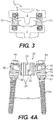
- FIG. 3 illustrates a posterior view of the system 8 of FIGS. 1-2 .
- the system 8 can include one or more flexible stabilization units 10 that can be implanted on a posterior portion of the spine to stabilize affected vertebrae 2, 4.
- each functionally dynamic stabilization unit 10 may comprise a flexible coupler 20 connected to at least one bone anchor 50, such as a pedicle screw or bone screw.
- the coupler 20 may comprise a flexible body 22 including slots 24 and openings 26.
- the flexible body 22 may include, at one end, a gripping arm 30 having an opening 32 for insertion of a bone anchor 50, and at an opposite end a second gripping arm 40, also having an opening 33 for receiving a bone anchor 50.
- the gripping arms 30, 40 may be integrally formed with the body 22 or may be detachably connected to the body 22.
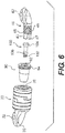
- one end of the gripping arm 40 may be threaded for connection to the flexible body 22 via, for example, a sleeve 90 in the flexible body 22, as shown in FIG. 6 .
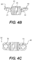
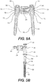
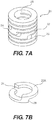
- Each gripping arm 30, 40 of the coupler 20 can include, on one side, a concavely-shaped cavity 34, 44 configured to seat against a semi-spherical ball bearing 60, shown in FIGS. 5A-5B , and 6 .
- the ball bearing 60 can have a through-hole, allowing it to fit over the bone anchor 50.
- the bone anchor 50 may have an elongate, threaded shaft 52 extending into a flange 56 that connects to a head portion 54 upon which the ball bearing 60 may be placed.
- the flange 56 may further include serrations 57 to facilitate anchorage to bone tissue and reduce loosening of the anchor 50 over time.
- the bone anchor 50 may be, for example, a pedicle screw.
- the bone anchor 50 can be cannulated to enable the unit 10 or system 8 to be percutaneously delivered.
- the concavely-shaped cavities 34, 44 allow the gripping arms to slide or rotate with respect to the bearing 60, thereby enabling the gripping arms 30, 40 to move relative to the bone anchor 50.
- Other appropriate structures may be used to connect the flexible body 22 to the bone anchors 50 while permitting relative movement between the two.
- a washer 70 may be placed onto the screw 50 and against the flange 56 or nut 80.
- the washer 70 can be configured and shaped to lie against the ball bearing 60.
- An assembled functionally dynamic stabilization unit 10 would further include a nut 80 screwed onto the head portion 54 of the screw 50 to secure the components to one another, as illustrated in FIGS. 4A and 5A .
- Each functionally dynamic stabilization unit 10 is configured to allow a range of motion or displacement of between 1.5 and 3.0 mm, where displacement may be measured from the center of a first pedicle screw connected to a first gripping arm 30 to the center of a second pedicle screw connected to the second gripping arm 40.
- This displacement or range of motion may be achieved, for example, through rotation, extension, or translation.
- FIG. 6 illustrates an exploded view of the flexible coupler of FIGS. 4A-4C .
- one of the gripping arms 40 may be removably attached to the coupler 20.
- the coupler 20 can include a threaded opening 28 for securing the second gripping arm 40, and other components, to the coupler 20.
- there may be a sleeve 90 having an opening 92 at one end and including a threaded rim 94 around the opening 92 for threadably connecting to the coupler body 22.
- the sleeve 90 can be configured to reside within the coupler body 22 and to receive and cooperate with a pin 100.
- the pin 100 can comprise an elongate body 102 with a threaded end, the body 102 extending into a semispherical head region 104 and including a skirt or shoulder region 106.
- the sleeve 90 and pin 100 form an extension and compression stop within the coupler body 22, functioning to limit range of motion of the flexible coupler 20 to the patient's neutral or active zone.
- the rim 92 of the sleeve 90 may be threaded to engage the threaded end 46 of the detachable second gripping arm 40.
- the overall length of the coupler 20 may be adjusted by varying the amount of threading of the second gripping arm 40 into the sleeve 90 (i.e., varying the number of rotations of the arm 40 into the sleeve 90).
- the threaded end 46 of the detachable second gripping arm 40 may extend into a plurality of compressible finger projections 43, each projection 43 terminating at a flanged lip 47.
- the flanged lip 47 serves as a locking mechanism, preventing the second gripping arm 40 from being unscrewed from the sleeve 90 after assembly.
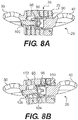
- the threaded end 46 may also include a well 48 for receiving an elastomeric plug 110, as shown in FIG. 8C .
- the elastomeric plug 110 may be formed of a soft, compliant plastic material such as, for example, silicone, polyethylene, or polyethyletherketone (PEEK).
- PEEK polyethyletherketone
- the plug 110 interacts with the threaded opening 92, reducing the slack or play between the arm 40 and the sleeve 90.
- Other suitable structures that permit adjustment of the length of the flexible body while providing control of the amount of compression and extension of the flexible body may also be used.
- a gripping arm can be attached at a friction fit, a telescoping connection, or using a ratchet mechanism.
- the coupler body 22 may include a cylindrical body comprised of a series of coil units 22A.
- the series of coil units 22 when connected to one another to form a stepwise series of slots 24, whereby each slot 24 terminates at an opening 26 of the flexible body 22.
- the series of coil units 22A can be formed from a single piece of material such that the units 22A are integrally connected with one another.
- the coil units 22A can be etched or cut from a single, tubular piece of material.
- one or more coil units 22A can be formed individually and stacked upon one another. The stacked coil units 22A can be connected to one another, for example, by welding or through mechanical connections.
- the coupler body 22 may vary in degree of stiffness based on the height, width, distance or angle between two adjacent slots 24 and the number of units 22A forming the coupler body 22. Further, one or more units 22A may be formed from different materials so as to vary the mechanical properties of the body 22. In addition, the dimensions of the units 22A, slots 24, and openings 26 can be varied within a single body 22.
- FIGS. 8A-8D show an embodiment of the fully assembled flexible coupler 20 in a resting state ( FIGS. 8A and 8D ), fully-expanded or distracted state ( FIG. 8B ), and a fully compressed state ( FIG. 8C ).
- the pin 100 and sleeve 90 are not engaged (i.e., free of resistive forces or encumbrances).
- the fully-expanded or distracted state FIG.
- the pin head 104 having a dimension that is larger than the width of the narrowed opening 98, abuts the narrowed opening 98 of the sleeve 90, preventing the flexible coupler body 22 from over expanding.
- the end of the sleeve 90 with the narrowed opening 98 abuts the inner edge of the first gripping arm 30, as shown.
- the cooperation of the sleeve 90 and pin 100 inside the coupler body 22 provides a distraction-compression stopping mechanism to control or limit the range of motion that can be offered, preventing not only injury or damage to the affected vertebral segments but also to the functionally dynamic stabilization unit itself.
- Other types of cooperating elements such as, for example, a telescoping element or internal piston, may be sued to control or limit the range of motion of the coupler body 22.
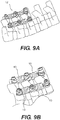
- the functionally dynamic stabilization unit 10 may be used alone to stabilize a pair of vertebral segments. Further, if desired, more than one unit 10 may be used in combination to form a multi-level, functionally dynamic stabilization system 12, as shown in FIGS. 9A and 9B .
- the multi-level, functionally dynamic stabilization system 12 may include two or more of the units 10 connected to one another.
- FIG. 10 illustrates a side view of the system shown in FIGS. 9A-9B .
- the system 12 includes a pair of flexible couplers 20 connected in series.
- the couplers 20 are positioned such that the first gripping arm 30 of each coupler 20 is placed around one ball bearing 60, with a bone anchor 50 and nut 80 securing the combination together. It is understood that more than two couplers 20 may be connected in this manner, and either the first 30 or second 40 gripping arm of any single coupler may be combined with the first 30 or second 40 gripping arm of another coupler 20 on a bone anchor 50.
- Any number of couplers 20 may be implanted either along one side, or on both sides, of a patient's spine. Further, the units 10 may have differing mechanical properties according to the patient's pathology and anatomy.
- the stabilization systems of the present disclosure can allow fusion of one or more vertebral motion segments, along with functionally dynamic stabilization of other motion segments.
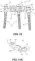
- the stabilization system may include a rigid, fusion-promoting coupler 101, such as the one shown in FIG. 11A .
- the rigid coupler 101 can be configured for use with the bone anchors 50, ball bearings 60, and washers 70 described previously.
- the rigid coupler 101 comprises two components 122, 124, each of which extends to a gripping arm 130, 140, respectively, in a manner similar to that in the flexible coupler 20 previously described.
- Each of the arms 130,140 includes an opening 132 for attachment to a bone anchor 50, in a manner similar to that described with respect to the flexible coupler 20.
- the two components 122,124 may be attached to one another to allow adjustment of the length of the rigid coupler 101.
- the components 122,124 can include threaded surfaces, and the length of the rigid coupler 101 can be adjusted by twisting one component 122 with respect to the other component 124, much like the manner previously described for adjusting the length of the flexible coupler 20.
- Each of the gripping arms 130,140 can also include, on an underside, a concave cavity 134,144, respectively, configured to seat against a semi-spherical ball bearing 60.
- the implantation of the rigid coupler 101 to the bone anchors 50 is similar to that for the flexible coupler 20, as previously described.
- a rigid, fusion-promoting coupler 201 may be provided.
- the rigid, fusion-promoting coupler 201 is similar to rigid coupler 101 except that it may not utilize threaded surfaces of components for adjusting a length of the coupler 201.
- the rigid coupler 201 can be configured for use with the bone anchors 50, ball bearings 60, and washers 70 described previously.
- the rigid coupler 201 comprises two components 222, 224, each of which extends to a gripping arm 230, 240, respectively, in a manner similar to that in the flexible coupler 20 previously described.
- Each of the arms 230, 240 includes an opening (not shown) for attachment to a bone anchor 50, in a manner similar to that described with respect to the flexible coupler 20.
- Each of the gripping arms 230, 240 can also include, on an underside, a concave cavity 234, 244, respectively, configured to seat against a semi-spherical ball bearing 60.
- the first component 222 and the second component 224 may be movable relative to one another to facilitate adjustment of the length of the coupler 201.
- the component 222 may include a cavity 226 configured to receive a fastening element 230 to secure the first component 222 relative to the second component 224. Because the first and second components do not include threaded surfaces, they may be moved relative to one another by sliding the components rather than twisting. Such an embodiment permits the surgeon to adjust the length of the rigid coupler 201 in situ as necessary.
- the fastening element 230 may be any suitable fastening element such as a screw or a nut.
- the fastening element 230 may comprise a break-away nut having a first portion configured to fixingly engage the portion 226 of component 222 to fix the position of the first component 222 relative to the second component and a second portion configured to engage an insertion tool for tightening of the first portion to the rigid coupler.
- the second portion of the break-away nut may be a break-away portion that has a thinner wall or area of lower yield-strength material, and is configured to break when a sufficient torque is applied (i.e., when the nut 230 has been sufficiently tightened).
- An internal surface of cavity 226 and an external surface of the fastening element 230 may be provided with threads to facilitate engagement of the cavity 226 with the fastening element 230.
- the stabilization system may include both functionally dynamic, flexible couplers 20 and rigid couplers 101, thereby providing a modular system that allows the combination of motion preservation and fusion at discrete segments of the patient's spine.
- the surgeon will have greater flexibility to address the specific needs of the patient. Therefore, one spinal segment may have functionally dynamic stabilization (i.e., non-fusion), while an adjacent segment may have rigid, segmental fixation (i.e., fusion).
- FIG. 12 illustrates a multi-segmental system 12 comprising three discreet stabilization units 10a, 10b, 10c utilizing flexible couplers 20a, 20b and a rigid coupler 101.
- the flexible couplers 20a, 20b of units 10a and 10c increase the segmental stiffness of the affected motion segment and restrict the range of motion in flexion, extension, lateral bending and rotation, while preserving motion.
- the posterior segmental height can be adjusted as well.
- the rigid, fusion-promoting coupler 101 of unit 10b provides rigid, segmental fixation, thereby promoting fusion, while utilizing the same type of bone anchors 50 and instruments.
- an implanted system may include only functionally dynamic, flexible couplers 20 connected to vertebra with bone anchors 50, as described above.
- an implanted system may include only functionally dynamic, flexible couplers 20 connected to vertebra with bone anchors 50, as described above.
- the units and systems of the present disclosure can be implanted using a minimally-invasive, muscle-sparing approach.
- Such approaches can include percutaneous methods or a series of small incisions that minimize tissue damage.
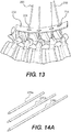
- FIGS. 13-19 illustrate exemplary embodiments of insertion instruments that may be provided separately or as a set along with the system.
- a series of K-wires 200 are inserted into the pedicles of the patient's spine.
- the K-wires 200 may be inserted through a series of small incisions in the patient's back.
- a wire template 202 may be provided to assist the surgeon in placement of the incisions and K-wires 200.
- the wire template 202 may include predetermined openings 204 that align with the pedicles of the patient's spine, as illustrated.
- the openings 204 may be bilaterally located in line with both pedicles of vertebrae to be treated.
- the template may be provided in various sizes to accommodate patients having variations in pedicle spacing.
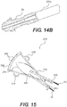
- the cannulated bone anchors 50 may be passed over the K-wires 200, and using a series of extension rods 220a, 220b, 220c, shown in FIG. 14A , the bone anchors can be implanted within selected vertebra. As shown in FIG. 14B , the extension rods can attach to the head portions 54 of the bone anchors 50 to allow manipulation of the anchors 50. In addition, a dilatation sleeve (not shown) can be provided, and the extension rods can be passed through the dilation sleeve to access the implantation site.
- the extension rods 220 can be used to manipulate the anchors 50 and the attached vertebrae to ascertain the full range of motion in a static condition and with an applied load. Such information may be useful to the surgeon to predict the possible range of corrective motion desirable for that spine segment.
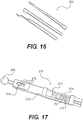
- a caliper 240 may also be provided with the instrument set.
- the caliper 240 can comprise a pair of pivoting arms 242, 244, each arm extending to a finger engaging opening 246, 248, respectively, and terminating at an opposite end into a gripping end 250, 252, respectively.
- the pivoting arms 242, 244 can be connected via a leaf spring 254.
- the ends of the arms 242, 244 are configured to provide a reading or measurement of the distance between a pair of adjacent bone anchors 50 using the indicia markings 258 on a backboard 256.
- the gripping ends 250, 252 can be configured to hold a portion of the ball bearing 60 of each bone anchor 50. This enables the caliper 240 to function even when the bone anchors 50 are situated in a nonparallel or unique angle relative to one another.
- FIG. 16 illustrates various rod extensions 260 that are configured to connect to other components of the anchor, such as the ball bearing 60, washer 70, or nut 80.
- Each of these rod extensions 260 enables minimally-invasive or percutaneous manipulation of the respective component.
- a coupler length adjuster 270 may be provided to ensure that the coupler length is correct prior to insertion.
- the length adjuster 270 may include a body 272 having a pair of grips 271, between which a coupler 20,101 can be held.
- the pair of grips 271 form the insertion area 274 for the coupler.
- Within the body 272 is a spring-loaded mechanism that exerts biased force against one of the grips 271.
- the spring- loaded mechanism may be controlled by turning a knob 280, thereby twisting the coupler 20,101, and consequently adjusting its length.
- the body 272 may further include a window 278 within which there appear indicia 276 indicating the length of the coupler.
- a flexible coupler 20 is illustrated, it is understood that the length adjuster 270 is also applicable for use with a rigid coupler 101.
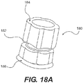
- FIG. 18A illustrates an exemplary embodiment of a suitable nut 180 having a break-away portion 182, connecting an anchor- engaging lower portion 186 to an upper portion 184.
- the break-away portion 182, having a thinner wall or area of lower yield-strength material, is configured to break when a sufficient torque is applied (i.e., when the nut 180 has been sufficiently tightened).
- FIG. 19 shows an exemplary insertion tool 290 useful for insertion of the nut 180.
- the insertion tool 290 comprises an elongate body 292 extending from a handle portion 294 to a nut coupling end 296 at an opposite end.
- the coupling end 296 may be configured to securely attach to the nut at the upper portion 184, as shown in FIG. 18B , and the elongate body 292, with a nut coupled thereto, can be inserted into a previously defined access site to secure the nut 180 to a bone anchor 50.
- the nut 180 will break at break-away portion 182, leaving the lower portion 186 on a bone anchor and allowing the upper portion 184 to be withdrawn.
- the surgeon may elect to repeat this process at an adjacent level until all the affected levels of the patient's spine have been treated.
- the entire process may be done percutaneously and/or with minimal disruption to the surrounding tissue.
Claims (15)
- Coupleur flexible (20) pour une unité de stabilisation vertébrale (10), le coupleur (20) ayant un corps (22), une paire de bras (30, 40), les bras (30, 40) étant positionnés au niveau d'extrémités opposées du coupleur (20), et un mécanisme de limitation d'amplitude des mouvements configuré de façon à contrôler une ampleur de flexion, une ampleur de compression, et une ampleur d'extension du coupleur ;
le mécanisme de limitation d'amplitude des mouvements comprenant un manchon (90) s'étendant intérieurement à partir d'une première extrémité du coupleur (20) vers une deuxième extrémité du coupleur (20) et ayant une ouverture distale rétrécie (98), et un corps allongé (100) s'étendant intérieurement à partir de la deuxième extrémité du coupleur (20) vers la première extrémité du coupleur (20) et ayant une extrémité agrandie (104) disposée au sein du manchon (90) et étant dimensionnée de sorte que l'extrémité agrandie (104) aboute contre la paroi de l'ouverture rétrécie (98) lorsque le coupleur (20) est allongé ou fléchi ;
caractérisé en ce que
le manchon (90) aboute contre la deuxième extrémité du coupleur (20) lorsque le coupleur (20) est comprimé. - Coupleur flexible (20) selon la revendication 1, dans lequel au moins l'un des bras (30, 40) est raccordé au corps (22) du coupleur flexible (20) au niveau d'un raccord fileté.
- Coupleur flexible selon l'une des revendications précédentes, dans lequel le corps (22) est extensible et compressible le long d'un axe longitudinal du corps (22).
- Coupleur flexible (20) selon l'une des revendications précédentes, dans lequel le corps (22) peut être fléchi le long de son axe.
- Coupleur flexible (20) selon l'une des revendications précédentes, dans lequel le corps (22) est cylindrique et inclut une pluralité d'éléments (22A) formant des fentes (24) au sein du corps (22).
- Coupleur flexible (20) selon l'une des revendications précédentes, dans lequel une longueur du coupleur flexible (20) est ajustable.
- Coupleur flexible (20) selon la revendication 6, dans lequel l'un des bras (30, 40) est attaché au coupleur (20) au niveau d'un raccord fileté, et la longueur du coupleur (20) peut être ajustée par rotation du bras (30, 40) par rapport au raccord fileté.
- Coupleur flexible (20) selon l'une des revendications précédentes, dans lequel le mouvement du corps allongé (100) relativement au manchon (90) dans une première direction définit une amplitude d'extension du coupleur (20), et un mouvement du corps allongé (100) relativement au manchon (90) dans une deuxième direction, opposée à la première direction, définit une amplitude de compression du coupleur (20).
- Coupleur flexible (20) selon l'une des revendications précédentes, dans lequel le mécanisme de limitation d'amplitude des mouvements est situé dans le corps (22).
- Unité de stabilisation vertébrale (10) comprenant un coupleur flexible selon l'une des revendications précédentes, l'unité (10) comprenant en outre un système d'ancrage incluant une pluralité d'ancres osseuses (50) configurées pour coopérer avec les bras (30, 40) du coupleur flexible (20) pour attacher le coupleur (20) à un os.
- Unité (10) selon la revendication 10, dans laquelle le système d'ancrage osseux inclut en outre au moins une articulation sphérique (60) et au moins un écrou (80).
- Unité (10) selon l'une des revendications 10 et 11, dans laquelle chaque bras (30, 40) inclut une portion concave (34, 44) ayant une ouverture (32, 33), et le système d'ancrage inclut en outre une articulation semi-sphérique (60) pour chaque ancre osseuse (50).
- Unité (10) selon la revendication 12, dans laquelle le coupleur flexible (20) est apte à bouger relativement à la pluralité d'ancres osseuses (50).
- Unité (10) selon l'une des revendications 11 à 13, dans laquelle le coupleur flexible (20) est configuré de façon à être apte à bouger relativement au système d'ancrage.
- Unité (10) selon l'une des revendications 11 à 14, dans laquelle le système d'ancrage inclut en outre une pluralité d'écrous (180), chaque écrou (180) ayant une portion rétrécie cassable (182) configurée de façon à se rompre lorsqu'un couple suffisant est appliqué à l'écrou (180).
Applications Claiming Priority (4)
| Application Number | Priority Date | Filing Date | Title |
|---|---|---|---|
| US86934206P | 2006-12-10 | 2006-12-10 | |
| US91436007P | 2007-04-27 | 2007-04-27 | |
| PCT/US2007/086800 WO2008073830A1 (fr) | 2006-12-10 | 2007-12-07 | Système de stabilisation postérieure fonctionnellement dynamique |
| EP07865393.8A EP2120748B1 (fr) | 2006-12-10 | 2007-12-07 | Système de stabilisation postérieure dynamique |
Related Parent Applications (1)
| Application Number | Title | Priority Date | Filing Date |
|---|---|---|---|
| EP07865393.8A Division EP2120748B1 (fr) | 2006-12-10 | 2007-12-07 | Système de stabilisation postérieure dynamique |
Publications (3)
| Publication Number | Publication Date |
|---|---|
| EP3216407A2 EP3216407A2 (fr) | 2017-09-13 |
| EP3216407A3 EP3216407A3 (fr) | 2017-10-11 |
| EP3216407B1 true EP3216407B1 (fr) | 2019-07-10 |
Family
ID=39323009
Family Applications (2)
| Application Number | Title | Priority Date | Filing Date |
|---|---|---|---|
| EP07865393.8A Active EP2120748B1 (fr) | 2006-12-10 | 2007-12-07 | Système de stabilisation postérieure dynamique |
| EP16184594.6A Active EP3216407B1 (fr) | 2006-12-10 | 2007-12-07 | Système de stabilisation fonctionnellement dynamique postérieure |
Family Applications Before (1)
| Application Number | Title | Priority Date | Filing Date |
|---|---|---|---|
| EP07865393.8A Active EP2120748B1 (fr) | 2006-12-10 | 2007-12-07 | Système de stabilisation postérieure dynamique |
Country Status (14)
| Country | Link |
|---|---|
| US (3) | US8920473B2 (fr) |
| EP (2) | EP2120748B1 (fr) |
| JP (1) | JP2010512228A (fr) |
| KR (1) | KR20090097909A (fr) |
| CN (1) | CN102525623B (fr) |
| AR (1) | AR064204A1 (fr) |
| AU (1) | AU2007333199B2 (fr) |
| CA (1) | CA2671868A1 (fr) |
| ES (1) | ES2601355T3 (fr) |
| HK (3) | HK1138168A1 (fr) |
| IL (1) | IL198962A0 (fr) |
| MX (1) | MX2009005843A (fr) |
| TW (1) | TW200843691A (fr) |
| WO (1) | WO2008073830A1 (fr) |
Families Citing this family (73)
| Publication number | Priority date | Publication date | Assignee | Title |
|---|---|---|---|---|
| US20160242816A9 (en) | 2001-05-09 | 2016-08-25 | Roger P. Jackson | Dynamic spinal stabilization assembly with elastic bumpers and locking limited travel closure mechanisms |
| US10258382B2 (en) | 2007-01-18 | 2019-04-16 | Roger P. Jackson | Rod-cord dynamic connection assemblies with slidable bone anchor attachment members along the cord |
| US7862587B2 (en) | 2004-02-27 | 2011-01-04 | Jackson Roger P | Dynamic stabilization assemblies, tool set and method |
| US10729469B2 (en) | 2006-01-09 | 2020-08-04 | Roger P. Jackson | Flexible spinal stabilization assembly with spacer having off-axis core member |
| DE10320417A1 (de) * | 2003-05-07 | 2004-12-02 | Biedermann Motech Gmbh | Dynamische Verankerungsvorrichtung und dynamische Stabilisierungseinrichtung für Knochen, insbesondere für Wirbel, mit einer derartigen Verankerungsvorrichtung |
| US8900270B2 (en) * | 2004-02-17 | 2014-12-02 | Gmedelaware 2 Llc | Facet joint replacement instruments and methods |
| US11241261B2 (en) | 2005-09-30 | 2022-02-08 | Roger P Jackson | Apparatus and method for soft spinal stabilization using a tensionable cord and releasable end structure |
| US8523904B2 (en) | 2004-03-09 | 2013-09-03 | The Board Of Trustees Of The Leland Stanford Junior University | Methods and systems for constraint of spinous processes with attachment |
| US7458981B2 (en) | 2004-03-09 | 2008-12-02 | The Board Of Trustees Of The Leland Stanford Junior University | Spinal implant and method for restricting spinal flexion |
| US9216041B2 (en) * | 2009-06-15 | 2015-12-22 | Roger P. Jackson | Spinal connecting members with tensioned cords and rigid sleeves for engaging compression inserts |
| US7901437B2 (en) | 2007-01-26 | 2011-03-08 | Jackson Roger P | Dynamic stabilization member with molded connection |
| US8187307B2 (en) | 2006-10-19 | 2012-05-29 | Simpirica Spine, Inc. | Structures and methods for constraining spinal processes with single connector |
| US8029541B2 (en) | 2006-10-19 | 2011-10-04 | Simpirica Spine, Inc. | Methods and systems for laterally stabilized constraint of spinous processes |
| US8162982B2 (en) | 2006-10-19 | 2012-04-24 | Simpirica Spine, Inc. | Methods and systems for constraint of multiple spine segments |
| US9867640B2 (en) | 2006-12-07 | 2018-01-16 | Nexus Spine, LLC | Press-on pedicle screw assembly |
| US8366745B2 (en) | 2007-05-01 | 2013-02-05 | Jackson Roger P | Dynamic stabilization assembly having pre-compressed spacers with differential displacements |
| US8475498B2 (en) | 2007-01-18 | 2013-07-02 | Roger P. Jackson | Dynamic stabilization connecting member with cord connection |
| US11224463B2 (en) | 2007-01-18 | 2022-01-18 | Roger P. Jackson | Dynamic stabilization connecting member with pre-tensioned flexible core member |
| US10383660B2 (en) | 2007-05-01 | 2019-08-20 | Roger P. Jackson | Soft stabilization assemblies with pretensioned cords |
| US8162987B2 (en) | 2007-06-05 | 2012-04-24 | Spartek Medical, Inc. | Modular spine treatment kit for dynamic stabilization and motion preservation of the spine |
| US8114134B2 (en) | 2007-06-05 | 2012-02-14 | Spartek Medical, Inc. | Spinal prosthesis having a three bar linkage for motion preservation and dynamic stabilization of the spine |
| US8083772B2 (en) | 2007-06-05 | 2011-12-27 | Spartek Medical, Inc. | Dynamic spinal rod assembly and method for dynamic stabilization of the spine |
| US8021396B2 (en) | 2007-06-05 | 2011-09-20 | Spartek Medical, Inc. | Configurable dynamic spinal rod and method for dynamic stabilization of the spine |
| US8092501B2 (en) | 2007-06-05 | 2012-01-10 | Spartek Medical, Inc. | Dynamic spinal rod and method for dynamic stabilization of the spine |
| WO2008151091A1 (fr) | 2007-06-05 | 2008-12-11 | Spartek Medical, Inc. | Système de tiges déflectrices pour un système d'implants spinaux à stabilisation dynamique et préservation du mouvement, et procédé correspondant |
| US8048115B2 (en) | 2007-06-05 | 2011-11-01 | Spartek Medical, Inc. | Surgical tool and method for implantation of a dynamic bone anchor |
| US20110172708A1 (en) * | 2007-06-22 | 2011-07-14 | Simpirica Spine, Inc. | Methods and systems for increasing the bending stiffness of a spinal segment with elongation limit |
| JP2010530780A (ja) | 2007-06-22 | 2010-09-16 | シンピライカ スパイン, インコーポレイテッド | 脊髄分節の制御された屈曲制限のための方法およびデバイス |
| US20100036424A1 (en) * | 2007-06-22 | 2010-02-11 | Simpirica Spine, Inc. | Methods and systems for increasing the bending stiffness and constraining the spreading of a spinal segment |
| EP2364656B1 (fr) * | 2007-10-11 | 2013-04-03 | Biedermann Technologies GmbH & Co. KG | Barre et système de barre modulaire pour stabilisation de la colonne vertébrale |
| US8894687B2 (en) | 2011-04-25 | 2014-11-25 | Nexus Spine, L.L.C. | Coupling system for surgical construct |
| US9232965B2 (en) * | 2009-02-23 | 2016-01-12 | Nexus Spine, LLC | Press-on link for surgical screws |
| US8333792B2 (en) | 2008-02-26 | 2012-12-18 | Spartek Medical, Inc. | Load-sharing bone anchor having a deflectable post and method for dynamic stabilization of the spine |
| US8083775B2 (en) | 2008-02-26 | 2011-12-27 | Spartek Medical, Inc. | Load-sharing bone anchor having a natural center of rotation and method for dynamic stabilization of the spine |
| US8016861B2 (en) | 2008-02-26 | 2011-09-13 | Spartek Medical, Inc. | Versatile polyaxial connector assembly and method for dynamic stabilization of the spine |
| US8337536B2 (en) | 2008-02-26 | 2012-12-25 | Spartek Medical, Inc. | Load-sharing bone anchor having a deflectable post with a compliant ring and method for stabilization of the spine |
| US8057517B2 (en) | 2008-02-26 | 2011-11-15 | Spartek Medical, Inc. | Load-sharing component having a deflectable post and centering spring and method for dynamic stabilization of the spine |
| US8097024B2 (en) | 2008-02-26 | 2012-01-17 | Spartek Medical, Inc. | Load-sharing bone anchor having a deflectable post and method for stabilization of the spine |
| US8007518B2 (en) | 2008-02-26 | 2011-08-30 | Spartek Medical, Inc. | Load-sharing component having a deflectable post and method for dynamic stabilization of the spine |
| US8211155B2 (en) | 2008-02-26 | 2012-07-03 | Spartek Medical, Inc. | Load-sharing bone anchor having a durable compliant member and method for dynamic stabilization of the spine |
| US8267979B2 (en) | 2008-02-26 | 2012-09-18 | Spartek Medical, Inc. | Load-sharing bone anchor having a deflectable post and axial spring and method for dynamic stabilization of the spine |
| US8187305B2 (en) * | 2008-06-06 | 2012-05-29 | Simpirica Spine, Inc. | Methods and apparatus for deploying spinous process constraints |
| US8308771B2 (en) | 2008-06-06 | 2012-11-13 | Simpirica Spine, Inc. | Methods and apparatus for locking a band |
| JP2012529969A (ja) | 2008-08-01 | 2012-11-29 | ロジャー・ピー・ジャクソン | スリーブ付き張力付与りコードを備える長手方向接続部材 |
| WO2010096621A2 (fr) | 2009-02-19 | 2010-08-26 | Bowden Anton E | Implant spinal dynamique élastique |
| WO2010104975A1 (fr) * | 2009-03-10 | 2010-09-16 | Simpirica Spine, Inc. | Dispositif d'attache chirurgicale et procédés d'utilisation |
| EP2405840B1 (fr) | 2009-03-10 | 2024-02-21 | Empirical Spine, Inc. | Dispositif d'attache chirurgicale |
| JP2012520131A (ja) | 2009-03-10 | 2012-09-06 | シンピライカ スパイン, インコーポレイテッド | 外科用テザー装置および使用方法 |
| WO2010108010A2 (fr) | 2009-03-19 | 2010-09-23 | Halverson Peter A | Implant spinal |
| US8668719B2 (en) * | 2009-03-30 | 2014-03-11 | Simpirica Spine, Inc. | Methods and apparatus for improving shear loading capacity of a spinal segment |
| US8292927B2 (en) * | 2009-04-24 | 2012-10-23 | Warsaw Orthopedic, Inc. | Flexible articulating spinal rod |
| US8105360B1 (en) | 2009-07-16 | 2012-01-31 | Orthonex LLC | Device for dynamic stabilization of the spine |
| US9157497B1 (en) | 2009-10-30 | 2015-10-13 | Brigham Young University | Lamina emergent torsional joint and related methods |
| US8257397B2 (en) | 2009-12-02 | 2012-09-04 | Spartek Medical, Inc. | Low profile spinal prosthesis incorporating a bone anchor having a deflectable post and a compound spinal rod |
| DE102010000339A1 (de) | 2010-02-08 | 2011-08-11 | Aesculap AG, 78532 | Verbindungselement für ein Wirbelsäulenstabilisierungssystem und Wirbelsäulenstabilisierungssystem |
| US8518085B2 (en) | 2010-06-10 | 2013-08-27 | Spartek Medical, Inc. | Adaptive spinal rod and methods for stabilization of the spine |
| JP2013540468A (ja) | 2010-09-08 | 2013-11-07 | ロジャー・ピー・ジャクソン | 弾性部および非弾性部を有する動的固定化部材 |
| DE102010060101A1 (de) | 2010-09-20 | 2012-03-22 | Aesculap Ag | Wirbelsäulenstabilisierungssystem und chirurgische Vorrichtung zum temporären Versteifen eines flexiblen Zwischenabschnitts eines Verbindungselements des Wirbelsäulenstabilisierungssystems |
| US8721566B2 (en) | 2010-11-12 | 2014-05-13 | Robert A. Connor | Spinal motion measurement device |
| US9095332B2 (en) | 2011-02-09 | 2015-08-04 | Redyns Medical Llc | Method and apparatus for attaching an elongated object to bone |
| EP2717807A2 (fr) * | 2011-06-07 | 2014-04-16 | Brigham Young University | Dispositif de stabilisation rachidienne en serpentin |
| US8430916B1 (en) | 2012-02-07 | 2013-04-30 | Spartek Medical, Inc. | Spinal rod connectors, methods of use, and spinal prosthesis incorporating spinal rod connectors |
| DE102012202750A1 (de) | 2012-02-22 | 2013-08-22 | Aces Gmbh | Dynamische stabilisierungseinrichtung für die wirbelsäule |
| US9402673B2 (en) | 2012-09-28 | 2016-08-02 | DePuy Synthes Products, Inc. | Devices and methods for breaking and retaining surgical reduction tabs |
| DE102013110173A1 (de) | 2013-09-16 | 2015-03-19 | Aesculap Ag | Verbindungselement und Wirbelsäulenstabilisierungssystem |
| EP3111099B1 (fr) | 2014-02-24 | 2020-04-01 | Curtin University Of Technology | Élément de fixation |
| FR3018678B1 (fr) * | 2014-03-20 | 2016-03-11 | Spineway | Ensemble chirurgical, vis d'ancrage osseux et dispositif d'extension d'une telle vis faisant parties dudit ensemble chirurgical |
| US9642651B2 (en) | 2014-06-12 | 2017-05-09 | Brigham Young University | Inverted serpentine spinal stability device and associated methods |
| WO2017066475A1 (fr) * | 2015-10-13 | 2017-04-20 | Providence Medical Technology, Inc. | Dispositif et système de pose d'implant d'articulation vertébrale |
| AU2017233553B2 (en) | 2016-03-18 | 2022-02-03 | Curtin University | An expandable fastener for orthopaedic applications |
| FR3080759A1 (fr) * | 2018-05-02 | 2019-11-08 | Abdollah Yassine Moufid | Dispositif medical pour mesurer l'angulation d'une tige d'arthrodese rachidienne, l'angulation d'un segment rachidien arthrodese par vis pediculaires ou l'angulation d'osteotomies in situ en peroperatoire, au cours de la chirurgie rachidienne. |
| EP3897414A4 (fr) | 2018-12-21 | 2022-09-28 | Paradigm Spine, LLC. | Système modulaire de stabilisation de colonne vertébrale et instruments associés |
| US11723691B2 (en) * | 2019-12-25 | 2023-08-15 | Apifix Ltd | Biasing device for spinal device |
Family Cites Families (85)
| Publication number | Priority date | Publication date | Assignee | Title |
|---|---|---|---|---|
| CA252694A (fr) | 1923-06-25 | 1925-08-18 | Dacar Frank | Tendeur de fil metallique |
| FR2545350B1 (fr) | 1983-05-04 | 1985-08-23 | Cotrel Yves | Dispositif pour l'etaiement du rachis |
| US4570618A (en) | 1983-11-23 | 1986-02-18 | Henry Ford Hospital | Intervertebral body wire stabilization |
| US4604995A (en) | 1984-03-30 | 1986-08-12 | Stephens David C | Spinal stabilizer |
| US4743260A (en) | 1985-06-10 | 1988-05-10 | Burton Charles V | Method for a flexible stabilization system for a vertebral column |
| US4653481A (en) | 1985-07-24 | 1987-03-31 | Howland Robert S | Advanced spine fixation system and method |
| USRE36221E (en) | 1989-02-03 | 1999-06-01 | Breard; Francis Henri | Flexible inter-vertebral stabilizer as well as process and apparatus for determining or verifying its tension before installation on the spinal column |
| US5030220A (en) | 1990-03-29 | 1991-07-09 | Advanced Spine Fixation Systems Incorporated | Spine fixation system |
| FR2676911B1 (fr) | 1991-05-30 | 1998-03-06 | Psi Ste Civile Particuliere | Dispositif de stabilisation intervertebrale a amortisseurs. |
| FR2692952B1 (fr) | 1992-06-25 | 1996-04-05 | Psi | Amortisseurs perfectionnes a limite de deplacement. |
| JP2604957B2 (ja) | 1992-09-02 | 1997-04-30 | アドバンスト スパイン フィクセイション システムス,インコーポレイティド | 脊椎固定装置用の低い外形のねじ締結組立体 |
| FR2709247B1 (fr) | 1993-08-27 | 1995-09-29 | Martin Jean Raymond | Dispositif d'ancrage d'une instrumentation rachidienne sur une vertèbre. |
| FR2709246B1 (fr) | 1993-08-27 | 1995-09-29 | Martin Jean Raymond | Orthèse vertébrale implantée dynamique. |
| EP0677277A3 (fr) | 1994-03-18 | 1996-02-28 | Patrice Moreau | Ensemble prothétique rachidien. |
| US5545166A (en) | 1994-07-14 | 1996-08-13 | Advanced Spine Fixation Systems, Incorporated | Spinal segmental reduction derotational fixation system |
| US6273914B1 (en) | 1995-09-28 | 2001-08-14 | Sparta, Inc. | Spinal implant |
| US5693053A (en) | 1995-10-19 | 1997-12-02 | Sdgi Holdings, Inc. | Variable angle and transitional linking member |
| US6835207B2 (en) | 1996-07-22 | 2004-12-28 | Fred Zacouto | Skeletal implant |
| FR2751864B1 (fr) | 1996-08-01 | 1999-04-30 | Graf Henry | Dispositif pour relier et assister mecaniquement des vertebres entre elles |
| FR2755844B1 (fr) | 1996-11-15 | 1999-01-29 | Stryker France Sa | Systeme d'osteosynthese a deformation elastique pour colonne vertebrale |
| FR2771280B1 (fr) * | 1997-11-26 | 2001-01-26 | Albert P Alby | Dispositif de liaison vertebrale resilient |
| US6296644B1 (en) | 1998-08-26 | 2001-10-02 | Jean Saurat | Spinal instrumentation system with articulated modules |
| JP3855528B2 (ja) | 1999-03-30 | 2006-12-13 | 株式会社デンソー | 自動車用空調装置搭載構造および空調装置 |
| US6299613B1 (en) | 1999-04-23 | 2001-10-09 | Sdgi Holdings, Inc. | Method for the correction of spinal deformities through vertebral body tethering without fusion |
| FR2796828B1 (fr) * | 1999-07-27 | 2001-10-19 | Dev Sed Soc Et | Dispositif de liaison intervertebrale implantable |
| AU778410B2 (en) | 1999-12-01 | 2004-12-02 | Henry Graf | Intervertebral stabilising device |
| JP4202020B2 (ja) | 1999-12-20 | 2008-12-24 | ジンテーズ ゲゼルシャフト ミト ベシュレンクテル ハフツング | 脊柱の二つの隣接椎体の安定化用装置 |
| DE10004712C1 (de) | 2000-02-03 | 2001-08-09 | Aesculap Ag & Co Kg | Knochenplatte |
| US20020133155A1 (en) | 2000-02-25 | 2002-09-19 | Ferree Bret A. | Cross-coupled vertebral stabilizers incorporating spinal motion restriction |
| US6248106B1 (en) | 2000-02-25 | 2001-06-19 | Bret Ferree | Cross-coupled vertebral stabilizers |
| CN1176935C (zh) | 2000-06-20 | 2004-11-24 | 王新华 | 克拉霉素2′-单丙酸酯十二烷基硫酸盐制备及其药用 |
| US6821277B2 (en) | 2000-06-23 | 2004-11-23 | University Of Southern California Patent And Copyright Administration | Percutaneous vertebral fusion system |
| US6964667B2 (en) | 2000-06-23 | 2005-11-15 | Sdgi Holdings, Inc. | Formed in place fixation system with thermal acceleration |
| US6875212B2 (en) | 2000-06-23 | 2005-04-05 | Vertelink Corporation | Curable media for implantable medical device |
| US6899713B2 (en) | 2000-06-23 | 2005-05-31 | Vertelink Corporation | Formable orthopedic fixation system |
| FR2812186B1 (fr) | 2000-07-25 | 2003-02-28 | Spine Next Sa | Piece de liaison souple pour la stabilisation du rachis |
| FR2812185B1 (fr) | 2000-07-25 | 2003-02-28 | Spine Next Sa | Piece de liaison semi-rigide pour la stabilisation du rachis |
| HU222694B1 (hu) | 2000-11-22 | 2003-09-29 | Sanatmetal Ortopédiai és Traumatológiai Eszközöket Gyártó Kft. | Sebészeti eszközkészlet csigolyák rögzítésére |
| FR2817461B1 (fr) | 2000-12-01 | 2003-08-15 | Henry Graf | Dispositif de stabilisation intervertebral |
| WO2002054935A2 (fr) | 2000-12-29 | 2002-07-18 | Thomas James C Jr | Systeme d'alignement vertebral |
| FR2819711B1 (fr) | 2001-01-23 | 2003-08-01 | Stryker Spine Sa | Systeme de reglage en position pour instrument de chirurgie rachidienne |
| US7229441B2 (en) | 2001-02-28 | 2007-06-12 | Warsaw Orthopedic, Inc. | Flexible systems for spinal stabilization and fixation |
| US6706044B2 (en) | 2001-04-19 | 2004-03-16 | Spineology, Inc. | Stacked intermedular rods for spinal fixation |
| US7314467B2 (en) | 2002-04-24 | 2008-01-01 | Medical Device Advisory Development Group, Llc. | Multi selective axis spinal fixation system |
| GB0114783D0 (en) | 2001-06-16 | 2001-08-08 | Sengupta Dilip K | A assembly for the stabilisation of vertebral bodies of the spine |
| FR2827498B1 (fr) | 2001-07-18 | 2004-05-14 | Frederic Fortin | Dispositif de liaison vertebrale souple constitue d'elements palliant une deficience du rachis |
| US6783527B2 (en) | 2001-10-30 | 2004-08-31 | Sdgi Holdings, Inc. | Flexible spinal stabilization system and method |
| AU2002218099B2 (en) * | 2001-12-07 | 2006-04-27 | Synthes Gmbh | Damping element |
| US6966910B2 (en) | 2002-04-05 | 2005-11-22 | Stephen Ritland | Dynamic fixation device and method of use |
| EP1585427B1 (fr) | 2002-05-08 | 2012-04-11 | Stephen Ritland | Dispositif de fixation dynamique |
| ATE299671T1 (de) | 2002-05-21 | 2005-08-15 | Spinelab Gmbh | Elastisches stabilisiersystem für wirbelsäulen |
| US20030220643A1 (en) | 2002-05-24 | 2003-11-27 | Ferree Bret A. | Devices to prevent spinal extension |
| DE10236691B4 (de) | 2002-08-09 | 2005-12-01 | Biedermann Motech Gmbh | Dynamische Stabilisierungseinrichtung für Knochen, insbesondere für Wirbel |
| FR2844180B1 (fr) | 2002-09-11 | 2005-08-05 | Spinevision | Element de liaison pour la stabilisation dynamique d'un systeme de fixation rachidien et systeme de fixation rachidien comportant un tel element |
| EP1567073B1 (fr) * | 2002-12-06 | 2014-04-02 | Synthes GmbH | Dispositif pour stabiliser des os |
| US7104992B2 (en) | 2003-01-14 | 2006-09-12 | Ebi, L.P. | Spinal fixation system |
| US7473267B2 (en) | 2003-04-25 | 2009-01-06 | Warsaw Orthopedic, Inc. | System and method for minimally invasive posterior fixation |
| BRPI0410697A (pt) | 2003-05-02 | 2006-06-20 | Univ Yale | método e estabilizador dinámico de espinha |
| US20050177164A1 (en) | 2003-05-02 | 2005-08-11 | Carmen Walters | Pedicle screw devices, systems and methods having a preloaded set screw |
| US8652175B2 (en) | 2003-05-02 | 2014-02-18 | Rachiotek, Llc | Surgical implant devices and systems including a sheath member |
| US20050182401A1 (en) | 2003-05-02 | 2005-08-18 | Timm Jens P. | Systems and methods for spine stabilization including a dynamic junction |
| US7615068B2 (en) | 2003-05-02 | 2009-11-10 | Applied Spine Technologies, Inc. | Mounting mechanisms for pedicle screws and related assemblies |
| US20050171543A1 (en) | 2003-05-02 | 2005-08-04 | Timm Jens P. | Spine stabilization systems and associated devices, assemblies and methods |
| US7635379B2 (en) | 2003-05-02 | 2009-12-22 | Applied Spine Technologies, Inc. | Pedicle screw assembly with bearing surfaces |
| US6986771B2 (en) | 2003-05-23 | 2006-01-17 | Globus Medical, Inc. | Spine stabilization system |
| DE10327358A1 (de) | 2003-06-16 | 2005-01-05 | Ulrich Gmbh & Co. Kg | Implantat zur Korrektur und Stabilisierung der Wirbelsäule |
| US7137985B2 (en) | 2003-09-24 | 2006-11-21 | N Spine, Inc. | Marking and guidance method and system for flexible fixation of a spine |
| US7815665B2 (en) | 2003-09-24 | 2010-10-19 | N Spine, Inc. | Adjustable spinal stabilization system |
| US20050203513A1 (en) | 2003-09-24 | 2005-09-15 | Tae-Ahn Jahng | Spinal stabilization device |
| US7763052B2 (en) | 2003-12-05 | 2010-07-27 | N Spine, Inc. | Method and apparatus for flexible fixation of a spine |
| DE10348329B3 (de) | 2003-10-17 | 2005-02-17 | Biedermann Motech Gmbh | Stabförmiges Element für die Anwendung in der Wirbelsäulen- oder Unfallchirurgie,Stabilisierungseinrichtung mit einem solchen stabförmigen Element und Herstellungsverfahren für das stabförmige Element |
| US8632570B2 (en) | 2003-11-07 | 2014-01-21 | Biedermann Technologies Gmbh & Co. Kg | Stabilization device for bones comprising a spring element and manufacturing method for said spring element |
| US7862586B2 (en) | 2003-11-25 | 2011-01-04 | Life Spine, Inc. | Spinal stabilization systems |
| US20050131407A1 (en) | 2003-12-16 | 2005-06-16 | Sicvol Christopher W. | Flexible spinal fixation elements |
| US20050143737A1 (en) | 2003-12-31 | 2005-06-30 | John Pafford | Dynamic spinal stabilization system |
| DE102004010844A1 (de) | 2004-03-05 | 2005-10-06 | Biedermann Motech Gmbh | Stabilisierungseinrichtung zur dynamischen Stabilisierung von Wirbeln oder Knochen und stabförmiges Element für eine derartige Stabilisierungseinrichtung |
| DE102004011685A1 (de) * | 2004-03-09 | 2005-09-29 | Biedermann Motech Gmbh | Stabförmiges Element für die Anwendung in der Wirbelsäulen- oder Unfallchirurgie und Stabilisierungseinrichtung mit einem solchen stabförmigen Element |
| US20050228380A1 (en) | 2004-04-09 | 2005-10-13 | Depuy Spine Inc. | Instruments and methods for minimally invasive spine surgery |
| US7648520B2 (en) | 2004-04-16 | 2010-01-19 | Kyphon Sarl | Pedicle screw assembly |
| US7854752B2 (en) * | 2004-08-09 | 2010-12-21 | Theken Spine, Llc | System and method for dynamic skeletal stabilization |
| US8162985B2 (en) * | 2004-10-20 | 2012-04-24 | The Board Of Trustees Of The Leland Stanford Junior University | Systems and methods for posterior dynamic stabilization of the spine |
| US7361196B2 (en) * | 2005-02-22 | 2008-04-22 | Stryker Spine | Apparatus and method for dynamic vertebral stabilization |
| US7811309B2 (en) * | 2005-07-26 | 2010-10-12 | Applied Spine Technologies, Inc. | Dynamic spine stabilization device with travel-limiting functionality |
| US7942905B2 (en) * | 2006-04-20 | 2011-05-17 | Warsaw Orthopedic, Inc. | Vertebral stabilizer |
| ES2394670T3 (es) * | 2008-10-08 | 2013-02-04 | Biedermann Technologies Gmbh & Co. Kg | Dispositivo de implante alargado y dispositivo de estabilización vertebral |
-
2007
- 2007-12-07 EP EP07865393.8A patent/EP2120748B1/fr active Active
- 2007-12-07 AR ARP070105504A patent/AR064204A1/es unknown
- 2007-12-07 US US11/952,575 patent/US8920473B2/en active Active
- 2007-12-07 CA CA002671868A patent/CA2671868A1/fr not_active Abandoned
- 2007-12-07 WO PCT/US2007/086800 patent/WO2008073830A1/fr active Application Filing
- 2007-12-07 CN CN201110438899.1A patent/CN102525623B/zh not_active Expired - Fee Related
- 2007-12-07 EP EP16184594.6A patent/EP3216407B1/fr active Active
- 2007-12-07 AU AU2007333199A patent/AU2007333199B2/en active Active
- 2007-12-07 JP JP2009541493A patent/JP2010512228A/ja active Pending
- 2007-12-07 KR KR1020097014142A patent/KR20090097909A/ko not_active Application Discontinuation
- 2007-12-07 ES ES07865393.8T patent/ES2601355T3/es active Active
- 2007-12-07 MX MX2009005843A patent/MX2009005843A/es not_active Application Discontinuation
- 2007-12-07 TW TW096146803A patent/TW200843691A/zh unknown
-
2009
- 2009-05-26 IL IL198962A patent/IL198962A0/en unknown
-
2010
- 2010-04-30 HK HK10104299.8A patent/HK1138168A1/xx not_active IP Right Cessation
-
2012
- 2012-11-01 HK HK12110986.1A patent/HK1170141A1/xx not_active IP Right Cessation
-
2014
- 2014-12-29 US US14/585,097 patent/US9522018B2/en active Active
-
2016
- 2016-12-19 US US15/383,536 patent/US10092329B2/en active Active
-
2018
- 2018-03-12 HK HK18103391.9A patent/HK1244416B/zh unknown
Non-Patent Citations (1)
| Title |
|---|
| None * |
Also Published As
| Publication number | Publication date |
|---|---|
| ES2601355T3 (es) | 2017-02-14 |
| US9522018B2 (en) | 2016-12-20 |
| AR064204A1 (es) | 2009-03-18 |
| US8920473B2 (en) | 2014-12-30 |
| CN102525623B (zh) | 2015-04-29 |
| AU2007333199B2 (en) | 2014-04-17 |
| TW200843691A (en) | 2008-11-16 |
| HK1170141A1 (en) | 2013-02-22 |
| IL198962A0 (en) | 2010-02-17 |
| WO2008073830A1 (fr) | 2008-06-19 |
| HK1138168A1 (en) | 2010-08-20 |
| US20170095274A1 (en) | 2017-04-06 |
| CN102525623A (zh) | 2012-07-04 |
| AU2007333199A1 (en) | 2008-06-19 |
| US10092329B2 (en) | 2018-10-09 |
| WO2008073830A9 (fr) | 2009-01-15 |
| CA2671868A1 (fr) | 2008-06-19 |
| EP2120748A1 (fr) | 2009-11-25 |
| US20150216567A1 (en) | 2015-08-06 |
| US20080312693A1 (en) | 2008-12-18 |
| MX2009005843A (es) | 2009-06-16 |
| JP2010512228A (ja) | 2010-04-22 |
| EP3216407A2 (fr) | 2017-09-13 |
| KR20090097909A (ko) | 2009-09-16 |
| EP2120748B1 (fr) | 2016-08-24 |
| HK1244416B (zh) | 2020-03-20 |
| EP3216407A3 (fr) | 2017-10-11 |
Similar Documents
| Publication | Publication Date | Title |
|---|---|---|
| US10092329B2 (en) | Posterior functionally dynamic stabilization system | |
| US8758410B2 (en) | Modular pedicle screw system | |
| US8425565B2 (en) | Modular percutaneous spinal fusion | |
| US7608096B2 (en) | Posterior pedicle screw and plate system and methods | |
| EP1970031A2 (fr) | Système de stabilisation spinale dynamique et son procédé d'utilisation | |
| US20110040331A1 (en) | Posterior stabilizer | |
| EP3193754A1 (fr) | Systèmes de fusion à niveau unique et procédés d'assemblage et d'utilisation | |
| US20230200857A1 (en) | Modular spine stabilization system and associated instruments | |
| US11419595B2 (en) | Interspinous, interlaminar space expander and measurement instrument | |
| KR100507615B1 (ko) | 척추경 나사못 및 이를 갖는 척추경 나사못 조립체 | |
| CN101573081B (zh) | 后路机能动态稳定系统 |
Legal Events
| Date | Code | Title | Description |
|---|---|---|---|
| PUAI | Public reference made under article 153(3) epc to a published international application that has entered the european phase |
Free format text: ORIGINAL CODE: 0009012 |
|
| STAA | Information on the status of an ep patent application or granted ep patent |
Free format text: STATUS: THE APPLICATION HAS BEEN PUBLISHED |
|
| PUAL | Search report despatched |
Free format text: ORIGINAL CODE: 0009013 |
|
| AC | Divisional application: reference to earlier application |
Ref document number: 2120748 Country of ref document: EP Kind code of ref document: P |
|
| AK | Designated contracting states |
Kind code of ref document: A2 Designated state(s): AT BE BG CH CY CZ DE DK EE ES FI FR GB GR HU IE IS IT LI LT LU LV MC MT NL PL PT RO SE SI SK TR |
|
| AK | Designated contracting states |
Kind code of ref document: A3 Designated state(s): AT BE BG CH CY CZ DE DK EE ES FI FR GB GR HU IE IS IT LI LT LU LV MC MT NL PL PT RO SE SI SK TR |
|
| RIC1 | Information provided on ipc code assigned before grant |
Ipc: A61B 17/88 20060101ALN20170907BHEP Ipc: A61B 17/17 20060101ALI20170907BHEP Ipc: A61B 17/70 20060101AFI20170907BHEP |
|
| STAA | Information on the status of an ep patent application or granted ep patent |
Free format text: STATUS: REQUEST FOR EXAMINATION WAS MADE |
|
| 17P | Request for examination filed |
Effective date: 20180410 |
|
| RBV | Designated contracting states (corrected) |
Designated state(s): AT BE BG CH CY CZ DE DK EE ES FI FR GB GR HU IE IS IT LI LT LU LV MC MT NL PL PT RO SE SI SK TR |
|
| RIC1 | Information provided on ipc code assigned before grant |
Ipc: A61B 17/88 20060101ALN20180516BHEP Ipc: A61B 17/70 20060101AFI20180516BHEP Ipc: A61B 17/17 20060101ALI20180516BHEP |
|
| GRAP | Despatch of communication of intention to grant a patent |
Free format text: ORIGINAL CODE: EPIDOSNIGR1 |
|
| STAA | Information on the status of an ep patent application or granted ep patent |
Free format text: STATUS: GRANT OF PATENT IS INTENDED |
|
| INTG | Intention to grant announced |
Effective date: 20180626 |
|
| REG | Reference to a national code |
Ref country code: HK Ref legal event code: DE Ref document number: 1244416 Country of ref document: HK |
|
| GRAS | Grant fee paid |
Free format text: ORIGINAL CODE: EPIDOSNIGR3 |
|
| RAP1 | Party data changed (applicant data changed or rights of an application transferred) |
Owner name: PARADIGM SPINE, LLC |
|
| RAP1 | Party data changed (applicant data changed or rights of an application transferred) |
Owner name: PARADIGM SPINE, LLC. |
|
| GRAA | (expected) grant |
Free format text: ORIGINAL CODE: 0009210 |
|
| STAA | Information on the status of an ep patent application or granted ep patent |
Free format text: STATUS: THE PATENT HAS BEEN GRANTED |
|
| AC | Divisional application: reference to earlier application |
Ref document number: 2120748 Country of ref document: EP Kind code of ref document: P |
|
| AK | Designated contracting states |
Kind code of ref document: B1 Designated state(s): AT BE BG CH CY CZ DE DK EE ES FI FR GB GR HU IE IS IT LI LT LU LV MC MT NL PL PT RO SE SI SK TR |
|
| REG | Reference to a national code |
Ref country code: GB Ref legal event code: FG4D |
|
| REG | Reference to a national code |
Ref country code: CH Ref legal event code: EP Ref country code: AT Ref legal event code: REF Ref document number: 1152722 Country of ref document: AT Kind code of ref document: T Effective date: 20190715 |
|
| REG | Reference to a national code |
Ref country code: DE Ref legal event code: R096 Ref document number: 602007058833 Country of ref document: DE |
|
| REG | Reference to a national code |
Ref country code: IE Ref legal event code: FG4D |
|
| REG | Reference to a national code |
Ref country code: NL Ref legal event code: MP Effective date: 20190710 |
|
| REG | Reference to a national code |
Ref country code: LT Ref legal event code: MG4D |
|
| PG25 | Lapsed in a contracting state [announced via postgrant information from national office to epo] |
Ref country code: FI Free format text: LAPSE BECAUSE OF FAILURE TO SUBMIT A TRANSLATION OF THE DESCRIPTION OR TO PAY THE FEE WITHIN THE PRESCRIBED TIME-LIMIT Effective date: 20190710 Ref country code: SE Free format text: LAPSE BECAUSE OF FAILURE TO SUBMIT A TRANSLATION OF THE DESCRIPTION OR TO PAY THE FEE WITHIN THE PRESCRIBED TIME-LIMIT Effective date: 20190710 Ref country code: NL Free format text: LAPSE BECAUSE OF FAILURE TO SUBMIT A TRANSLATION OF THE DESCRIPTION OR TO PAY THE FEE WITHIN THE PRESCRIBED TIME-LIMIT Effective date: 20190710 Ref country code: LT Free format text: LAPSE BECAUSE OF FAILURE TO SUBMIT A TRANSLATION OF THE DESCRIPTION OR TO PAY THE FEE WITHIN THE PRESCRIBED TIME-LIMIT Effective date: 20190710 Ref country code: PT Free format text: LAPSE BECAUSE OF FAILURE TO SUBMIT A TRANSLATION OF THE DESCRIPTION OR TO PAY THE FEE WITHIN THE PRESCRIBED TIME-LIMIT Effective date: 20191111 Ref country code: BG Free format text: LAPSE BECAUSE OF FAILURE TO SUBMIT A TRANSLATION OF THE DESCRIPTION OR TO PAY THE FEE WITHIN THE PRESCRIBED TIME-LIMIT Effective date: 20191010 |
|
| PG25 | Lapsed in a contracting state [announced via postgrant information from national office to epo] |
Ref country code: LV Free format text: LAPSE BECAUSE OF FAILURE TO SUBMIT A TRANSLATION OF THE DESCRIPTION OR TO PAY THE FEE WITHIN THE PRESCRIBED TIME-LIMIT Effective date: 20190710 Ref country code: GR Free format text: LAPSE BECAUSE OF FAILURE TO SUBMIT A TRANSLATION OF THE DESCRIPTION OR TO PAY THE FEE WITHIN THE PRESCRIBED TIME-LIMIT Effective date: 20191011 Ref country code: ES Free format text: LAPSE BECAUSE OF FAILURE TO SUBMIT A TRANSLATION OF THE DESCRIPTION OR TO PAY THE FEE WITHIN THE PRESCRIBED TIME-LIMIT Effective date: 20190710 Ref country code: IS Free format text: LAPSE BECAUSE OF FAILURE TO SUBMIT A TRANSLATION OF THE DESCRIPTION OR TO PAY THE FEE WITHIN THE PRESCRIBED TIME-LIMIT Effective date: 20191110 |
|
| PG25 | Lapsed in a contracting state [announced via postgrant information from national office to epo] |
Ref country code: TR Free format text: LAPSE BECAUSE OF FAILURE TO SUBMIT A TRANSLATION OF THE DESCRIPTION OR TO PAY THE FEE WITHIN THE PRESCRIBED TIME-LIMIT Effective date: 20190710 |
|
| PGFP | Annual fee paid to national office [announced via postgrant information from national office to epo] |
Ref country code: AT Payment date: 20191125 Year of fee payment: 13 |
|
| PG25 | Lapsed in a contracting state [announced via postgrant information from national office to epo] |
Ref country code: RO Free format text: LAPSE BECAUSE OF FAILURE TO SUBMIT A TRANSLATION OF THE DESCRIPTION OR TO PAY THE FEE WITHIN THE PRESCRIBED TIME-LIMIT Effective date: 20190710 Ref country code: PL Free format text: LAPSE BECAUSE OF FAILURE TO SUBMIT A TRANSLATION OF THE DESCRIPTION OR TO PAY THE FEE WITHIN THE PRESCRIBED TIME-LIMIT Effective date: 20190710 Ref country code: EE Free format text: LAPSE BECAUSE OF FAILURE TO SUBMIT A TRANSLATION OF THE DESCRIPTION OR TO PAY THE FEE WITHIN THE PRESCRIBED TIME-LIMIT Effective date: 20190710 Ref country code: IT Free format text: LAPSE BECAUSE OF FAILURE TO SUBMIT A TRANSLATION OF THE DESCRIPTION OR TO PAY THE FEE WITHIN THE PRESCRIBED TIME-LIMIT Effective date: 20190710 Ref country code: DK Free format text: LAPSE BECAUSE OF FAILURE TO SUBMIT A TRANSLATION OF THE DESCRIPTION OR TO PAY THE FEE WITHIN THE PRESCRIBED TIME-LIMIT Effective date: 20190710 |
|
| PG25 | Lapsed in a contracting state [announced via postgrant information from national office to epo] |
Ref country code: SK Free format text: LAPSE BECAUSE OF FAILURE TO SUBMIT A TRANSLATION OF THE DESCRIPTION OR TO PAY THE FEE WITHIN THE PRESCRIBED TIME-LIMIT Effective date: 20190710 Ref country code: CZ Free format text: LAPSE BECAUSE OF FAILURE TO SUBMIT A TRANSLATION OF THE DESCRIPTION OR TO PAY THE FEE WITHIN THE PRESCRIBED TIME-LIMIT Effective date: 20190710 Ref country code: IS Free format text: LAPSE BECAUSE OF FAILURE TO SUBMIT A TRANSLATION OF THE DESCRIPTION OR TO PAY THE FEE WITHIN THE PRESCRIBED TIME-LIMIT Effective date: 20200224 |
|
| REG | Reference to a national code |
Ref country code: DE Ref legal event code: R097 Ref document number: 602007058833 Country of ref document: DE |
|
| PLBE | No opposition filed within time limit |
Free format text: ORIGINAL CODE: 0009261 |
|
| STAA | Information on the status of an ep patent application or granted ep patent |
Free format text: STATUS: NO OPPOSITION FILED WITHIN TIME LIMIT |
|
| PG2D | Information on lapse in contracting state deleted |
Ref country code: IS |
|
| REG | Reference to a national code |
Ref country code: CH Ref legal event code: PL |
|
| 26N | No opposition filed |
Effective date: 20200603 |
|
| REG | Reference to a national code |
Ref country code: BE Ref legal event code: MM Effective date: 20191231 |
|
| PG25 | Lapsed in a contracting state [announced via postgrant information from national office to epo] |
Ref country code: MC Free format text: LAPSE BECAUSE OF FAILURE TO SUBMIT A TRANSLATION OF THE DESCRIPTION OR TO PAY THE FEE WITHIN THE PRESCRIBED TIME-LIMIT Effective date: 20190710 Ref country code: SI Free format text: LAPSE BECAUSE OF FAILURE TO SUBMIT A TRANSLATION OF THE DESCRIPTION OR TO PAY THE FEE WITHIN THE PRESCRIBED TIME-LIMIT Effective date: 20190710 |
|
| PG25 | Lapsed in a contracting state [announced via postgrant information from national office to epo] |
Ref country code: FR Free format text: LAPSE BECAUSE OF NON-PAYMENT OF DUE FEES Effective date: 20191231 Ref country code: LU Free format text: LAPSE BECAUSE OF NON-PAYMENT OF DUE FEES Effective date: 20191207 Ref country code: IE Free format text: LAPSE BECAUSE OF NON-PAYMENT OF DUE FEES Effective date: 20191207 |
|
| PG25 | Lapsed in a contracting state [announced via postgrant information from national office to epo] |
Ref country code: CH Free format text: LAPSE BECAUSE OF NON-PAYMENT OF DUE FEES Effective date: 20191231 Ref country code: BE Free format text: LAPSE BECAUSE OF NON-PAYMENT OF DUE FEES Effective date: 20191231 Ref country code: LI Free format text: LAPSE BECAUSE OF NON-PAYMENT OF DUE FEES Effective date: 20191231 |
|
| PG25 | Lapsed in a contracting state [announced via postgrant information from national office to epo] |
Ref country code: CY Free format text: LAPSE BECAUSE OF FAILURE TO SUBMIT A TRANSLATION OF THE DESCRIPTION OR TO PAY THE FEE WITHIN THE PRESCRIBED TIME-LIMIT Effective date: 20190710 |
|
| PG25 | Lapsed in a contracting state [announced via postgrant information from national office to epo] |
Ref country code: MT Free format text: LAPSE BECAUSE OF FAILURE TO SUBMIT A TRANSLATION OF THE DESCRIPTION OR TO PAY THE FEE WITHIN THE PRESCRIBED TIME-LIMIT Effective date: 20190710 Ref country code: HU Free format text: LAPSE BECAUSE OF FAILURE TO SUBMIT A TRANSLATION OF THE DESCRIPTION OR TO PAY THE FEE WITHIN THE PRESCRIBED TIME-LIMIT; INVALID AB INITIO Effective date: 20071207 |
|
| REG | Reference to a national code |
Ref country code: AT Ref legal event code: MM01 Ref document number: 1152722 Country of ref document: AT Kind code of ref document: T Effective date: 20201207 |
|
| PG25 | Lapsed in a contracting state [announced via postgrant information from national office to epo] |
Ref country code: AT Free format text: LAPSE BECAUSE OF NON-PAYMENT OF DUE FEES Effective date: 20201207 |
|
| REG | Reference to a national code |
Ref country code: AT Ref legal event code: UEP Ref document number: 1152722 Country of ref document: AT Kind code of ref document: T Effective date: 20190710 |
|
| PGFP | Annual fee paid to national office [announced via postgrant information from national office to epo] |
Ref country code: GB Payment date: 20231121 Year of fee payment: 17 |
|
| PGFP | Annual fee paid to national office [announced via postgrant information from national office to epo] |
Ref country code: DE Payment date: 20231121 Year of fee payment: 17 |