EP3215642B1 - Verfahren und vorrichtung zum regeln des druckes im abgaskanal eines konverters - Google Patents
Verfahren und vorrichtung zum regeln des druckes im abgaskanal eines konverters Download PDFInfo
- Publication number
- EP3215642B1 EP3215642B1 EP15791539.8A EP15791539A EP3215642B1 EP 3215642 B1 EP3215642 B1 EP 3215642B1 EP 15791539 A EP15791539 A EP 15791539A EP 3215642 B1 EP3215642 B1 EP 3215642B1
- Authority
- EP
- European Patent Office
- Prior art keywords
- converter
- target pressure
- mouth
- value
- pressure value
- Prior art date
- Legal status (The legal status is an assumption and is not a legal conclusion. Google has not performed a legal analysis and makes no representation as to the accuracy of the status listed.)
- Active
Links
- 238000000034 method Methods 0.000 title claims description 24
- 230000015572 biosynthetic process Effects 0.000 claims description 24
- QVGXLLKOCUKJST-UHFFFAOYSA-N atomic oxygen Chemical compound [O] QVGXLLKOCUKJST-UHFFFAOYSA-N 0.000 claims description 20
- 239000001301 oxygen Substances 0.000 claims description 20
- 229910052760 oxygen Inorganic materials 0.000 claims description 20
- 239000000779 smoke Substances 0.000 claims description 19
- 230000006978 adaptation Effects 0.000 claims description 15
- 239000000463 material Substances 0.000 claims description 12
- 238000011156 evaluation Methods 0.000 claims description 9
- 230000001105 regulatory effect Effects 0.000 claims description 9
- 229910000831 Steel Inorganic materials 0.000 claims description 7
- 239000010959 steel Substances 0.000 claims description 7
- 230000003595 spectral effect Effects 0.000 claims description 6
- 230000007704 transition Effects 0.000 claims description 3
- 238000002844 melting Methods 0.000 claims description 2
- 230000008018 melting Effects 0.000 claims description 2
- 239000007769 metal material Substances 0.000 claims description 2
- 239000002912 waste gas Substances 0.000 claims 5
- 230000004913 activation Effects 0.000 claims 2
- 238000001514 detection method Methods 0.000 claims 1
- 239000007789 gas Substances 0.000 description 13
- 238000006243 chemical reaction Methods 0.000 description 9
- 230000008569 process Effects 0.000 description 9
- XEEYBQQBJWHFJM-UHFFFAOYSA-N Iron Chemical compound [Fe] XEEYBQQBJWHFJM-UHFFFAOYSA-N 0.000 description 8
- 239000012080 ambient air Substances 0.000 description 4
- 238000002485 combustion reaction Methods 0.000 description 4
- 229910052742 iron Inorganic materials 0.000 description 4
- 230000008901 benefit Effects 0.000 description 3
- 230000001276 controlling effect Effects 0.000 description 3
- CURLTUGMZLYLDI-UHFFFAOYSA-N Carbon dioxide Chemical compound O=C=O CURLTUGMZLYLDI-UHFFFAOYSA-N 0.000 description 2
- 230000005855 radiation Effects 0.000 description 2
- OKTJSMMVPCPJKN-UHFFFAOYSA-N Carbon Chemical compound [C] OKTJSMMVPCPJKN-UHFFFAOYSA-N 0.000 description 1
- UGFAIRIUMAVXCW-UHFFFAOYSA-N Carbon monoxide Chemical compound [O+]#[C-] UGFAIRIUMAVXCW-UHFFFAOYSA-N 0.000 description 1
- 208000001408 Carbon monoxide poisoning Diseases 0.000 description 1
- 239000002253 acid Substances 0.000 description 1
- 239000003570 air Substances 0.000 description 1
- 229910052799 carbon Inorganic materials 0.000 description 1
- 229910002092 carbon dioxide Inorganic materials 0.000 description 1
- 239000001569 carbon dioxide Substances 0.000 description 1
- 229910002091 carbon monoxide Inorganic materials 0.000 description 1
- 238000001816 cooling Methods 0.000 description 1
- 230000003111 delayed effect Effects 0.000 description 1
- 230000001419 dependent effect Effects 0.000 description 1
- 238000011982 device technology Methods 0.000 description 1
- 230000000694 effects Effects 0.000 description 1
- 238000002347 injection Methods 0.000 description 1
- 239000007924 injection Substances 0.000 description 1
- 238000010943 off-gassing Methods 0.000 description 1
- 230000009467 reduction Effects 0.000 description 1
- 230000004044 response Effects 0.000 description 1
Images
Classifications
-
- C—CHEMISTRY; METALLURGY
- C21—METALLURGY OF IRON
- C21C—PROCESSING OF PIG-IRON, e.g. REFINING, MANUFACTURE OF WROUGHT-IRON OR STEEL; TREATMENT IN MOLTEN STATE OF FERROUS ALLOYS
- C21C5/00—Manufacture of carbon-steel, e.g. plain mild steel, medium carbon steel or cast steel or stainless steel
- C21C5/28—Manufacture of steel in the converter
- C21C5/30—Regulating or controlling the blowing
- C21C5/32—Blowing from above
-
- C—CHEMISTRY; METALLURGY
- C21—METALLURGY OF IRON
- C21C—PROCESSING OF PIG-IRON, e.g. REFINING, MANUFACTURE OF WROUGHT-IRON OR STEEL; TREATMENT IN MOLTEN STATE OF FERROUS ALLOYS
- C21C5/00—Manufacture of carbon-steel, e.g. plain mild steel, medium carbon steel or cast steel or stainless steel
- C21C5/28—Manufacture of steel in the converter
- C21C5/38—Removal of waste gases or dust
-
- C—CHEMISTRY; METALLURGY
- C21—METALLURGY OF IRON
- C21C—PROCESSING OF PIG-IRON, e.g. REFINING, MANUFACTURE OF WROUGHT-IRON OR STEEL; TREATMENT IN MOLTEN STATE OF FERROUS ALLOYS
- C21C5/00—Manufacture of carbon-steel, e.g. plain mild steel, medium carbon steel or cast steel or stainless steel
- C21C5/28—Manufacture of steel in the converter
- C21C5/42—Constructional features of converters
- C21C5/46—Details or accessories
- C21C5/4673—Measuring and sampling devices
-
- F—MECHANICAL ENGINEERING; LIGHTING; HEATING; WEAPONS; BLASTING
- F27—FURNACES; KILNS; OVENS; RETORTS
- F27D—DETAILS OR ACCESSORIES OF FURNACES, KILNS, OVENS OR RETORTS, IN SO FAR AS THEY ARE OF KINDS OCCURRING IN MORE THAN ONE KIND OF FURNACE
- F27D19/00—Arrangements of controlling devices
-
- F—MECHANICAL ENGINEERING; LIGHTING; HEATING; WEAPONS; BLASTING
- F27—FURNACES; KILNS; OVENS; RETORTS
- F27D—DETAILS OR ACCESSORIES OF FURNACES, KILNS, OVENS OR RETORTS, IN SO FAR AS THEY ARE OF KINDS OCCURRING IN MORE THAN ONE KIND OF FURNACE
- F27D21/00—Arrangement of monitoring devices; Arrangement of safety devices
- F27D21/02—Observation or illuminating devices
-
- F—MECHANICAL ENGINEERING; LIGHTING; HEATING; WEAPONS; BLASTING
- F27—FURNACES; KILNS; OVENS; RETORTS
- F27D—DETAILS OR ACCESSORIES OF FURNACES, KILNS, OVENS OR RETORTS, IN SO FAR AS THEY ARE OF KINDS OCCURRING IN MORE THAN ONE KIND OF FURNACE
- F27D19/00—Arrangements of controlling devices
- F27D2019/0028—Regulation
- F27D2019/0071—Regulation using position sensors
-
- F—MECHANICAL ENGINEERING; LIGHTING; HEATING; WEAPONS; BLASTING
- F27—FURNACES; KILNS; OVENS; RETORTS
- F27D—DETAILS OR ACCESSORIES OF FURNACES, KILNS, OVENS OR RETORTS, IN SO FAR AS THEY ARE OF KINDS OCCURRING IN MORE THAN ONE KIND OF FURNACE
- F27D21/00—Arrangement of monitoring devices; Arrangement of safety devices
- F27D21/02—Observation or illuminating devices
- F27D2021/026—Observation or illuminating devices using a video installation
Definitions
- the invention relates to a method and a device for regulating the pressure in the exhaust passage of a converter in a steel mill to a predetermined pressure setpoint by suitable variation of manipulated variables.
- the predetermined pressure setpoint more specifically the predetermined negative pressure setpoint traditionally deliberately set too low for safety reasons too low, whereby the suction power of Blower is deliberately set stronger than would actually be required.
- increasing the suction power has the disadvantage that not only process gases, but also more ambient air is sucked into the exhaust gas duct, whereby carbon monoxide increasingly burns to carbon dioxide and therefore the calorific value of the process gas drops considerably.
- a variably positionable collar installed in order to influence the amount of sucked ambient air.
- the Japanese pamphlets JP 1165712 and JP 58177412 each disclose a method according to which the degree of opening of the converter mouth is controlled or regulated at the transition to the exhaust gas passage, depending on the extent of flame formation at the converter mouth.
- the extent of flame formation is detected by means of a suitable camera in the form of imagery, which is evaluated for the purpose of control with regard to the extent of flame formation.
- the disclosure WO 2007/109875 A1 the use of infrared sensors or filters when recording the flame image at the converter mouth.
- the pressure setpoint is specified as a function of the current position or the current opening degree of the adjusting ring on the converter mouth.
- the opening position of the adjusting ring is specifically detected by means of a position measuring device and converted by means of a conversion device into a suitable pressure setpoint.
- the conversion device traditionally simply assigns the measured opening positions of the adjusting ring to specific pressure setpoints with the aid of its conversion table.
- Such a simple tabular assignment of opening positions of the adjusting ring to pressure setpoints usually provides optimal results for the time of commissioning and the creation of this table.
- the pressure situation at the converter collar changes. This is among other things characterized by converter wear in the area of the converter mouth. This has the consequence that the initially made tabular assignment after some time is no longer optimal and again an increased false air combustion or an increased outgassing of process gases.
- the Japanese patent application JP S 56 160583 A discloses a method of controlling the pressure of the exhaust gas in an exhaust passage of a metallurgical furnace.
- the pressure in the exhaust duct should be kept constant if possible.
- a bypass passage is associated with the main exhaust passage, the opening degree of which can be regulated by means of valves. In this way, the pressure of the exhaust gas in the main exhaust duct can be adjusted as desired.
- the US patent application US 3,528,800 A. discloses an apparatus for controlling the operation of a basic oxygen furnace BOF in response to measured carbon reduction by the exhaust gases and oxygen supplied by a lance. Also in this invention, the pressure in the exhaust duct is measured.
- the international patent application WO 2011/151143 A2 relates to a method for determining the timing of ignition in the inflation process in a steel converter.
- the timing of the ignition in this context means the time of the beginning of the reaction of oxygen blown into the converter with the material to be melted. This time is usually delayed after the injection of oxygen. It is envisaged that the radiation produced during the ignition, which emerges between the converter and the extractor hood, is detected, in order then to determine the ignition point by evaluating the radiation images.
- the invention has the object, a known method and a known device for controlling the pressure in the exhaust passage of a converter to the effect that the pressure setpoint for the pressure control in the exhaust duct of the converter and regardless of the age or the operating hours of the Converter is always optimally specified.
- raw value means that value predetermined for the desired pressure value, which alone, typically with the aid of a conversion table, is derived from the detected opening position of the adjusting ring on the converter mouth.
- the raw value for the pressure setpoint is specified as a function of the measured opening degree of an adjusting ring or a hood on the converter mouth.
- the invention advantageously provides that not simply the raw value according to the conversion table, but the raw value is used only after adaptation to the current process events as a pressure setpoint for the pressure control in the exhaust duct.
- the adaptation of the raw value takes place as a function of the extent of smoke or flame formation at the mouth of the converter. Specifically, in the adaptation, the raw value is increased when the extent of smoke or flame formation is reduced, and vice versa.
- This claimed adaptation offers the advantage that the pressure setpoint, also for safety reasons, does not have to be set lower than would be required depending on the current process situation in the converter. In this way, the external entry of ambient air is minimized by the converter mouth and thus the undesired afterburning of process gas.
- the extent of smoke or flame formation is determined by evaluating image material, which represents the respectively current smoke or flame formation at the mouth of the converter during the converter operation.
- image material represents the respectively current smoke or flame formation at the mouth of the converter during the converter operation.
- the smoke formation is equated to flame formation. It is therefore not distinguished between smoke formation and flame formation. Rather, the extent of smoke or flame formation alone is evaluated in comparison with a situation in which neither smoke nor flame formation takes place at the converter mouth.
- the evaluation of the image material essentially only components in the infrared spectral range are evaluated and interference signals in the visible spectral range are suppressed.
- the evaluation of the image material in the infrared spectral range is completely sufficient; ie the visible spectral range can be ignored. In this way, computer power for the evaluation of the image material can be saved.
- the method according to the invention provides that the raw value is adapted not only as a function of the extent of smoke or flame formation, but also by an additional consideration of the amount of active oxygen fed into the converter.
- the supply of active oxygen into the converter is typically carried out in two ways: first by supplying a lance, especially when fresh, and secondly by supplying iron ore, in which large amounts of active oxygen are bound, but during the combustion process free become.
- the supplied amount of active oxygen from both parts is calculated. Specifically, in the adaptation, the raw value for the pressure setpoint is reduced as the amount of oxygen supplied is increased, and vice versa.
- the manipulated variables which are varied in the context of pressure control in order to keep the pressure in the exhaust passage constant to the predetermined pressure setpoint, serve either to drive only a flap or to simultaneously drive the flap and a suction fan in the exhaust passage.
- the above object of the invention is further achieved device technology by a device in a steel mill according to claim 6.
- the advantages of this device correspond to the advantages mentioned above with reference to the claimed method.
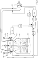
- the invention is attached to a figure which shows the device according to the invention.
- the figure shows a converter 100 for melting metallic material 300, typically scrap or iron ore.
- the converter 100 has at its upper end a converter mouth 120 as a transition to an exhaust passage 110.
- flaps 112 and / or a suction fan 114 are arranged as actuators for regulating the pressure in the exhaust passage 110.
- the converter mouth 120 is sealed off from the ambient air by a variably positionable collar 122.
- the degree of opening of the adjusting ring is z. B. with the help of hydraulic cylinders 124 variably adjustable. Furthermore, one is
- Blow lance 126 to detect the supply of active oxygen into the interior of the converter. So far, the technical elements described state of the art and subject of a steel plant.
- the device according to the invention has a pressure control loop 200 for regulating the pressure in the exhaust passage 110 of the converter 100.
- the control is carried out to a predetermined pressure setpoint P setpoint.
- the predetermined pressure setpoint is compared with the actual pressure P actual measured at the converter mouth 120 by a pressure measuring device 128.
- a controller determines suitable manipulated variables, ie Adjustment signals for the flap 112 or for the flap and the suction fan 114 in the exhaust passage 110. By changing the position of the flaps 112 and / or the power of the suction fan 114 then the actual pressure in the converter mouth is adjusted to the predetermined pressure setpoint P Soll .
- the present invention provides that the desired pressure value P Soll , as it is used as an input variable for the pressure control loop 200, is formed by adaptation of a predetermined raw value R for the desired pressure value.
- a position measuring device 150 is provided for detecting the opening position of the adjusting ring 122 on the converter mouth 120.
- the opening position of the adjusting ring 122 thus detected is converted in a conversion device 160 by means of a table into the raw value R for the pressure setpoint.
- an image capture device 130 typically a CMOS camera, preferably with an infrared filter, is provided for creating image material, which Converter mouth and possibly its environment during operation of the converter shows.
- the image capture device 130 serves to detect smoke and flame formation on the converter mouth 120.
- the image material thus obtained is evaluated by an image evaluation device 132 with regard to the extent of smoke or flame formation.
- the current extent of smoke or flame formation determined in this way is fed to a pressure setpoint calculation unit 210, also called raw value adaptation unit, for calculating the pressure setpoint value to be supplied to the pressure control loop 200 by adapting the raw value.
- the pressure setpoint calculation unit 210 performs an adaptation of the raw value also supplied thereto in dependence on the extent of smoke or flame formation at the converter mouth and in this way determines the pressure setpoint P Soll , which is fed to the pressure control loop 200 as an input variable.
- the adaptation of the raw value R can be further optimized by not taking into account for the adaptation to the extent of smoke or flame formation, but also the amount of active oxygen supplied to the converter 100.
- an acid detector 140 is provided for detecting the amount of active oxygen supplied to the converter.
- the total amount of oxygen fed in is composed, on the one hand, of the amount of oxygen fed in via the lance 126 and, on the other hand, of the amount of oxygen fed in via the iron ore, which is bound in the iron ore and released as part of the combustion.
Landscapes
- Engineering & Computer Science (AREA)
- Chemical & Material Sciences (AREA)
- Manufacturing & Machinery (AREA)
- Materials Engineering (AREA)
- Metallurgy (AREA)
- Organic Chemistry (AREA)
- Mechanical Engineering (AREA)
- General Engineering & Computer Science (AREA)
- Environmental & Geological Engineering (AREA)
- Waste-Gas Treatment And Other Accessory Devices For Furnaces (AREA)
Description
- Die Erfindung betrifft ein Verfahren und eine Vorrichtung zum Regeln des Druckes im Abgaskanal eines Konverters in einem Stahlwerk auf einen vorgegeben Drucksollwert durch geeignete Variation von Stellgrößen.
- Im Stand der Technik für Konverterstahlwerke, insbesondere für jene Konverterstahlwerke, die über eine Abgasrückgewinnungsanlage verfügen, ist es bekannt, den Druck, genauer gesagt den Unterdruck im Abgaskanal zu regeln. Im Rahmen der Regelung wird der Ist-Druck an der Konverterhaube oder im Kesselbereich, d. h. im Kühlkamin, gemessen und mit einem vorgegebenen Drucksollwert verglichen. Je nach Prozessphase ändert sich die Verbrennung und somit auch der Ist-Druck im Konverter. Die bekannte Druckregelung arbeitet derart, dass wenn der Ist-Druck an einem der genannten Messpunkte steigt, die Saugleistung eines Sauggebläses im Abgaskanal erhöht wird und umgekehrt.
- Da bei dem Betrieb des Konverterstahlwerkes die Personensicherheit an oberster Stelle steht und der Stahlwerksbetreiber insbesondere sicherstellen muss, dass das Bedienpersonal keine Kohlenmonoxid-Vergiftung erleidet, wird der vorgegebene Drucksollwert, genauer gesagt der vorgegebene Unterdrucksollwert traditionell aus Sicherheitsgründen bewusst zu niedrig vorgegeben, wodurch die Absaugleistung des Gebläses bewusst stärker eingestellt wird, als dies eigentlich erforderlich wäre. Das Erhöhen der Absaugleistung hat jedoch den Nachteil, dass nicht nur Prozessgase, sondern auch mehr Umgebungsluft in den Abgaskanal angesaugt wird, wodurch vermehrt Kohlenmonoxid zu Kohlendioxid nachverbrennt und der Heizwert des Prozessgases deshalb erheblich sinkt. Um solche unerwünschten Nachverbrennungen zu minimieren ist in den meisten Konverterstahlwerken, insbesondere bei den Konverterstahlwerken mit Abgasrückgewinnung am Konvertermund ein variabel positionierbarer Stellring installiert, um die Menge der angesaugten Umgebungsluft beeinflussen zu können.
- Die japanischen Druckschriften
JP 1165712 JP 58177412 WO 2007/109875 A1 die Verwendung von Infrarotsensoren bzw. Filtern bei der Aufnahme des Flammenbildes am Konvertermund. - Bei der traditionellen Druck- bzw. Unterdruckregelung im Abgaskanal wird der Drucksollwert in Abhängigkeit der jeweils aktuellen Stellung bzw. des aktuellen Öffnungsgrades des Stellrings am Konvertermund vorgegeben. Dazu wird konkret die Öffnungsposition des Stellrings mit Hilfe einer Positionsmesseinrichtung erfasst und mit Hilfe einer Umrechnungseinrichtung in einen geeigneten Drucksollwert umgerechnet. Die Umrechnungseinrichtung ordnet dabei traditionell einfach die gemessenen Öffnungspositionen des Stellrings mit Hilfe seiner Umrechnungstabelle bestimmten Drucksollwerten zu. Eine solche einfache tabellarische Zuordnung von Öffnungspositionen des Stellrings zu Drucksollwerten liefert für den Zeitpunkt der Inbetriebnahme und der Erstellung dieser Tabelle in der Regel optimale Ergebnisse. Bei steigendem Konverteralter ändert sich jedoch die Drucksituation am Konverterbund. Diese ist unter anderem geprägt von Konverterverschleiß im Bereich des Konvertermundes. Dies hat zur Folge, dass die ursprünglich vorgenommene tabellarische Zuordnung nach einiger Zeit nicht mehr optimal ist und wieder eine erhöhe Falschluftverbrennung oder ein erhöhtes Ausqualmen von Prozessgasen erfolgt.
- Die japanische Offenlegungsschrift
JP S 56 160583 A - Die US-Patentanmeldung
US 3 528 800 A offenbart eine Vorrichtung zur Steuerung des Betriebs eines Basic-Oxygen-Furnace BOF in Abhängigkeit einer gemessenen Kohlenstoffreduktion durch die Abgase und durch eine Blaslanze zugeführten Sauerstoffs. Auch bei dieser Erfindung wird der Druck im Abgaskanal gemessen. - Die internationale Patentanmeldung
WO 2011/151143 A2 betrifft ein Verfahren zum Bestimmen des Zeitpunktes der Zündung beim Aufblasverfahren in einem Stahlkonverter. Der Zeitpunkt der Zündung meint in diesem Zusammenhang den Zeitpunkt des Beginns der Reaktion von in den Konverter eingeblasenen Sauerstoffs mit dem zu schmelzenden Material. Dieser Zeitpunkt liegt üblicherweise zeitverzögert nach dem Einblasen des Sauerstoffs. Es ist vorgesehen, dass die bei der Zündung entstehende Strahlung, die zwischen Konverter und Abzugshaube austritt, detektiert wird, um dann durch Auswertung der Strahlungsbilder den Zündzeitpunkt zu ermitteln. - Ausgehend von diesem Stand der Technik liegt der Erfindung die Aufgabe zugrunde, ein bekanntes Verfahren und eine bekannte Vorrichtung zum Regeln des Druckes im Abgaskanal eines Konverters dahingehend weiterzubilden, dass der Drucksollwert für die Druckregelung im Abgaskanal des Konverters auch unabhängig vom Alter bzw. den Betriebsstunden des Konverters stets optimal vorgegeben wird.
- Diese Aufgabe wird durch das Verfahren gemäß Patentanspruch 1 gelöst.
- Der Begriff Rohwert meint im Rahmen der vorliegenden Beschreibung jenen für den Drucksollwert vorgegebenen Wert, der alleine, typischerweise mit Hilfe einer Umrechnungstabelle aus der erfassten Öffnungsposition des Stellrings am Konvertermund abgeleitet wird. Konkret wird der Rohwert für den Drucksollwert in Abhängigkeit des gemessenen Öffnungsgrades eines Stellrings oder einer Haube am Konvertermund vorgegeben.
- Die Erfindung sieht vorteilhafterweise vor, dass nicht einfach der Rohwert gemäß Umrechnungstabelle, sondern der Rohwert erst nach Adaption an das aktuelle Prozessgeschehen als Drucksollwert für die Druckregelung im Abgaskanal herangezogen wird. Im Anspruch 1 wird beansprucht, dass die Adaption des Rohwertes in Abhängigkeit des Ausmaßes der Qualm- oder Flammenbildung am Mund des Konverters erfolgt. Konkret wird bei der Adaption der Rohwert vergrößert, wenn das Ausmaß der Qualm- oder Flammenbildung reduziert wird und umgekehrt.
- Diese beanspruchte Adaption bietet den Vorteil, dass der Drucksollwert auch aus Sicherheitsgründen nicht niedriger angesetzt werden muss, als dies in Abhängigkeit der aktuellen Prozesssituation im Konverter erforderlich wäre. Auf diese Weise wird der Fremdeintrag von Umgebungsluft durch den Konvertermund und damit die unerwünschte Nachverbrennung von Prozessgas minimiert.
- Gemäß einem ersten Ausführungsbeispiel wird das Ausmaß der Qualm- oder Flammenbildung durch Auswerten von Bildmaterial ermittelt, welches die jeweils aktuelle Qualm- oder Flammenbildung am Mund des Konverters während des Konverterbetriebs darstellt. Bei der Auswertung des Bildmaterials wird die Qualmbildung der Flammenbildung gleichgesetzt. Es wird also nicht zwischen Qualmbildung und Flammenbildung unterschieden. Vielmehr wird alleine das Ausmaß der Qualm- oder Flammenbildung gegenüber einer Situation, bei der weder Qualm- noch Flammenbildung am Konvertermund stattfindet, bewertet.
- Vorteilhafterweise werden bei der Auswertung des Bildmaterials im Wesentlichen nur Anteile im infraroten Spektralbereich ausgewertet und Störsignale im sichtbaren Spektralbereich unterdrückt. Für die Zwecke der vorliegenden Erfindung, d. h. die Adaption des Rohwertes für den Drucksollwert ist die Auswertung des Bildmaterials im infraroten Spektralbereich völlig ausreichend; d. h. der sichtbare Spektralbereich kann ignoriert werden. Auf diese Weise kann Rechnerleistung für die Auswertung des Bildmaterials eingespart werden.
- Gemäß einem weiteren Ausführungsbeispiel sieht das erfindungsgemäße Verfahren vor, dass der Rohwert nicht nur in Abhängigkeit des Ausmaßes der Qualm- oder Flammenbildung, sondern weiterhin auch durch eine zusätzliche Berücksichtigung der Menge des in den Konverter zugeführten aktiven Sauerstoffs adaptiert wird. Die Zufuhr von aktivem Sauerstoff in den Konverter erfolgt typischerweise auf zweierlei Weise: Zum einen durch Zufuhr über eine Blaslanze, insbesondere beim Frischen, und zum anderen durch Zufuhr von Eisenerz, in dem große Mengen von aktivem Sauerstoff gebunden sind, die aber während des Verbrennungsprozesses frei werden. Für das erfindungsgemäße Verfahren wird die zugeführte Menge an aktivem Sauerstoff aus beiden Anteilen berechnet. Konkret wird im Rahmen der Adaption der Rohwert für den Drucksollwert verringert, wenn die Menge des zugeführten Sauerstoffs erhöht wird und umgekehrt.
- Die Stellgrößen, die im Rahmen der Druckregelung variiert werden, um den Druck im Abgaskanal auf den vorgegebenen Drucksollwert konstant zu halten, dienen entweder zum alleinigen Ansteuern einer Klappe oder zum gleichzeitigen Ansteuern der Klappe und eines Sauggebläses in dem Abgaskanal.
- Die oben genannte Aufgabe der Erfindung wird weiterhin vorrichtungstechnisch durch eine Vorrichtung in einem Stahlwerk gemäß Patentanspruch 6 gelöst. Die Vorteile dieser Vorrichtung entsprechen den oben mit Bezug auf das beanspruchte Verfahren genannten Vorteilen.
- Weitere vorteilhafte Ausgestaltungen der Vorrichtung sind Gegenstand der abhängigen Ansprüche.
- Der Erfindung ist eine Figur beigefügt, welche die erfindungsgemäße Vorrichtung zeigt.
- Die Figur zeigt einen Konverter 100 zum Schmelzen von metallischem Gut 300, typischerweise Schrott oder Eisenerz. DerKonverter 100 besitzt an seinem oberen Ende einen Konvertermund 120 als Übergang zu einem Abgaskanal 110. In dem Abgaskanal 110 sind Klappen 112 und/oder ein Sauggebläse 114 angeordnet als Stellglieder zum Regeln des Druckes in dem Abgaskanal 110. Der Konvertermund 120 ist gegenüber der Umgebungsluft abgeschottet durch einen variabel positionierbaren Stellring 122. Der Öffnungsgrad des Stellrings ist z. B. mit Hilfe von Hydraulikzylindern 124 variabel einstellbar. Weiterhin ist eine
- Blaslanze 126 zu erkennen zum Zuführen von aktivem Sauerstoff in das Innere des Konverters. Soweit sind die beschriebenen technischen Elemente Stand der Technik und Gegenstand eines Stahlwerks.
- Die erfindungsgemäße Vorrichtung weist einen Druckregelkreis 200 auf zum Regeln des Drucks in dem Abgaskanal 110 des Konverters 100. Die Regelung erfolgt auf einen vorgegebenen Drucksollwert PSoll. Im Rahmen der Regelung wird der vorgegebene Drucksollwert verglichen mit dem jeweils aktuell von einer Druckmesseinrichtung 128 gemessenen Ist-Druck PIst am Konvertermund 120. Aus der Regeldifferenz zwischen dem Drucksollwert und dem Druckistwert (PSoll minus PIst) ermittelt ein Regler geeignete Stellgrößen, d. h. Stellsignale für die Klappe 112 oder für die Klappe und das Sauggebläse 114 in dem Abgaskanal 110. Durch Veränderung der Stellung der Klappen 112 und/oder der Leistung des Sauggebläses 114 wird dann der Ist-Druck im Konvertermund an den vorgegebenen Drucksollwert PSoll angepasst.
- Die vorliegende Erfindung sieht vor, dass der Drucksollwert PSoll, wie er als Eingangsgröße für den Druckregelkreis 200 verwendet wird, durch Adaption eines vorgegebenen Rohwertes R für den Drucksollwert gebildet wird. Zur Ermittlung des Rohwertes ist zunächst eine Positionsmesseinrichtung 150 vorgesehen zum Erfassen der Öffnungsposition des Stellrings 122 am Konvertermund 120. Die so erfasste Öffnungsposition des Stellrings 122 wird in einer Umrechnungseinrichtung 160 mit Hilfe einer Tabelle in den Rohwert R für den Drucksollwert umgerechnet.
- Weil jedoch die Umrechnungstabelle mit zunehmender Betriebsstundenzahl des Konverters keine optimale Ermittlung der Rohwerte mehr ermöglicht, wird erfindungsgemäße eine Adaption des besagten Rohwertes an die aktuelle Prozesssituation vorgesehen. Zu diesem Zweck ist zunächst eine Bilderfassungseinrichtung 130, typischerweise eine CMOS-Kamera, vorzugsweise mit einem Infrarotfilter, vorgesehen zum Erstellen von Bildmaterial, welches den Konvertermund und gegebenenfalls seine Umgebung während des Betriebs des Konverters zeigt. Insbesondere dient die Bilderfassungseinrichtung 130 zum Erfassen von Qualm- und Flammenbildung am Konvertermund 120. Das so gewonnene Bildmaterial wird von einer Bildauswerteeinrichtung 132 im Hinblick auf das Ausmaß der Qualm- oder Flammenbildung ausgewertet. Das so ermittelte aktuelle Ausmaß der Qualm- oder Flammenbildung wird einer Drucksollwert-Berechnungseinheit 210, auch Rohwert-Adaptionseinheit genannt, zugeführt, zum Berechnen des dem Druckregelkreis 200 zuzuführenden Drucksollwertes durch Adaption des Rohwertes. Anders ausgedrückt, führt die Drucksollwert-Berechnungseinheit 210 eine Adaption des ihr ebenfalls zugeführten Rohwertes in Abhängigkeit des Ausmaßes der Qualm- oder Flammenbildung am Konvertermund durch und ermittelt auf diese Weise den Drucksollwert PSoll, welcher dem Druckregelkreis 200 als Eingangsgröße zugeführt wird.
- Die Adaption des Rohwertes R lässt sich weiter optimieren, indem zur Adaption nicht zur das Ausmaß der Qualm- oder Flammenbildung, sondern zusätzlich auch die Menge des dem Konverter 100 zugeführten aktiven Sauerstoffs mit berücksichtigt wird. Zu diesem Zweck ist eine Sauer-Erfassungseinrichtung 140 vorgesehen zum Erfassen der Menge des in den Konverter zugeführten aktiven Sauerstoffs. Die Gesamtmenge des zugeführten Sauerstoffs setzt sich zusammen zum einen aus der über die Blaslanze 126 zugeführten Menge an Sauerstoff und zum anderen aus der über das Eisenerz zugeführten Menge an Sauerstoff, welcher in dem Eisenerz gebunden ist und im Rahmen der Verbrennung frei wird.
-
- 100
- Konverter
- 110
- Abgaskanal
- 112
- Klappe
- 114
- Sauggebläse
- 120
- Konvertermund
- 122
- Stellring
- 124
- Hydraulikzylinder
- 126
- Blaslanze
- 128
- Druckmesseinrichtung
- 130
- Bilderfassungseinrichtung
- 132
- Bildauswerteeinrichtung
- 140
- Sauerstoff-Erfassungseinrichtung
- 150
- Positionsmesseinrichtung
- 160
- Umrechnungseinrichtung
- 200
- Druckregelkreis
- 210
- Drucksollwert-Berechnungseinheit
- 300
- metallisches Gut
- R
- Rohwert für den Drucksollwert
Claims (8)
- Verfahren zum Regeln des Druckes im Abgaskanal (110) eines Konverters (100) in einem Stahlwerk auf einen vorgegebenen Drucksollwert durch geeignete Variation von Stellgrößen,
gekennzeichnet durch folgende Schritte zur Ermittlung des Drucksollwertes:Vorgeben eines Rohwertes für den Drucksollwert in Abhängigkeit des gemessenen Öffnungsgrades eines Stellrings (122) am Konvertermund (120);
undErmitteln des Drucksollwertes durch Adaption des Rohwertes in Form einer Vergrößerung des Rohwertes, wenn das Ausmaß der Qualm- oder Flammenbildung am Mund (120) des Konverters reduziert wird, und umgekehrt. - Verfahren nach Anspruch 1,
dadurch gekennzeichnet, dass
das Ausmaß der Qualm- und Flammenbildung durch Auswerten von Bildmaterial ermittelt wird, welches die jeweils aktuelle Qualm- und Flammenbildung am Mund (120) des Konverters während eines Konverterbetriebs darstellt. - Verfahren nach Anspruch 2,
dadurch gekennzeichnet, dass
bei der Auswertung des Bildmaterials im Wesentlichen nur Anteile im infraroten Spektralbereich ausgewertet und Störsignale im sichtbaren Spektralbereich unterdrückt werden. - Verfahren nach einem der vorangegangenen Ansprüche,
dadurch gekennzeichnet, dass
der Rohwert weiterhin dergestalt adaptiert wird, dass der Rohwert verringert wird, wenn die Menge des zugeführten Sauerstoffs erhöht wird, und umgekehrt. - Verfahren nach einem der vorangegangenen Ansprüche,
dadurch gekennzeichnet, dass
die Stellgrößen entweder zum alleinigen Ansteuern einer Klappe (112) oder zum gleichzeitigen Ansteuern der Klappe (112) und eines Sauggebläses (114) in dem Abgaskanal des Konverters dienen. - Vorrichtung in einem Stahlwerk mit einem Konverter (100) zum Schmelzen von metallischem Gut (300), aufweisend:einen Druckregelkreis (200) zum Regeln des Drucks in dem Abgaskanal (110) des Konverters (100) auf einen vorgegebenen Drucksollwert durch geeignete Variation von Stellgrößen für Stellglieder (112, 114) in dem Abgaskanal, wobei dem Druckregelkreis (200) eine Drucksollwert-Berechnungseinheit (210) zugeordnet ist;dadurch gekennzeichnet, dassder Konverter an seinem Mund (120) im Übergang zu dem Abgaskanal (110) einen variabel positionierbaren Stellring (122) aufweist zum Öffnen und Schließen des Konvertermundes (120);eine Positionsmesseinrichtung (150) vorgesehen ist zum Erfassen der Öffnungsposition des Stellrings am Konvertermund;eine Umrechnungseinrichtung (160) vorgesehen ist zum Umrechnen verschiedener erfasster Öffnungspositionen in einen Rohwert für den Drucksollwert;eine Bilderfassungseinrichtung (130) vorgesehen ist zum Erstellen von Bildmaterial, welches den Konvertermund (120) und seine Umgebung während des Betriebs des Konverters zeigt;eine Bildauswerteeinrichtung (132) vorgesehen ist zum Ermitteln des Ausmaßes der Qualm- und Flammenbildung am Konvertermund (120) durch Auswerten des Bildmaterials;
unddie Drucksollwert-Berechnungseinheit (210) ausgebildet ist, den Drucksollwert zu berechnen durch Adaption des vorgegebenen Rohwertes (R) für den Drucksollwert in Abhängigkeit des Ausmaßes der Qualm- und Flammenbildung am Mund (120) des Konverters (100). - Vorrichtung nach Anspruch 6,
dadurch gekennzeichnet, dass
es sich bei der Bilderfassungseinrichtung (130) um eine CMOS-Kamerasystem handelt, vorzugsweise mit IR-Filter. - Vorrichtung nach Anspruch 6 oder 7,
dadurch gekennzeichnet, dass
eine Sauerstoff-Erfassungseinrichtung (140) vorgesehen ist zum Erfassen der Menge des in den Konverter (100) zugeführten aktiven Sauerstoffs; und die Drucksollwert-Berechnungseinheit (210) weiterhin ausgebildet ist, den Drucksollwert zu berechnen durch Adaption des Rohwertes dergestalt, dass der Rohwert verringert wird, wenn die Menge des zugeführten Sauerstoffs erhöht wird, und umgekehrt.
Applications Claiming Priority (2)
| Application Number | Priority Date | Filing Date | Title |
|---|---|---|---|
| DE102014222788.7A DE102014222788A1 (de) | 2014-11-07 | 2014-11-07 | Verfahren und Vorrichtung zum Regeln des Druckes im Abgaskanal eines Konverters |
| PCT/EP2015/074789 WO2016071145A1 (de) | 2014-11-07 | 2015-10-27 | Verfahren und vorrichtung zum regeln des druckes im abgaskanal eines konverters |
Publications (2)
| Publication Number | Publication Date |
|---|---|
| EP3215642A1 EP3215642A1 (de) | 2017-09-13 |
| EP3215642B1 true EP3215642B1 (de) | 2018-06-20 |
Family
ID=54478723
Family Applications (1)
| Application Number | Title | Priority Date | Filing Date |
|---|---|---|---|
| EP15791539.8A Active EP3215642B1 (de) | 2014-11-07 | 2015-10-27 | Verfahren und vorrichtung zum regeln des druckes im abgaskanal eines konverters |
Country Status (4)
| Country | Link |
|---|---|
| US (1) | US20170335417A1 (de) |
| EP (1) | EP3215642B1 (de) |
| DE (1) | DE102014222788A1 (de) |
| WO (1) | WO2016071145A1 (de) |
Families Citing this family (2)
| Publication number | Priority date | Publication date | Assignee | Title |
|---|---|---|---|---|
| MX2021012622A (es) | 2019-04-15 | 2021-11-12 | Arcelormittal | Metodo para controlar la aspiracion de humos de escape durante un proceso siderurgico. |
| DE102022207976A1 (de) | 2022-08-02 | 2024-02-08 | Sms Group Gmbh | Verfahren zur Herstellung von Stahl in einem metallurgischen Gefäß |
Family Cites Families (8)
| Publication number | Priority date | Publication date | Assignee | Title |
|---|---|---|---|---|
| US3528800A (en) * | 1966-02-14 | 1970-09-15 | Leeds & Northrup Co | Optimized blowing control for basic oxygen furnaces |
| JPS56160583A (en) * | 1980-05-15 | 1981-12-10 | Nippon Steel Corp | Application and control of exhaust gas |
| US4415412A (en) * | 1981-10-08 | 1983-11-15 | The United States Of America As Represented By The United States Department Of Energy | Production of anhydrous aluminum chloride composition and process for electrolysis thereof |
| JPS58177412A (ja) | 1982-04-12 | 1983-10-18 | Kawasaki Steel Corp | 転炉排ガス処理装置におけるフ−ド内圧力の制御方法 |
| JPH1165712A (ja) | 1997-08-11 | 1999-03-09 | Nec Gumma Ltd | 情報処理装置 |
| US8400960B2 (en) * | 2004-05-07 | 2013-03-19 | Koninklijke Philips Electronics N.V. | Method of distributive reservation of a medium in a radio communications network |
| CA2541092A1 (en) | 2006-03-28 | 2007-09-28 | Murray Thomson | Infrared light sensors for diagnosis and control of industrial furnace gases |
| AT509866B1 (de) * | 2010-06-02 | 2011-12-15 | Siemens Vai Metals Tech Gmbh | Verfahren zum bestimmen des zeitpunktes der zündung beim aufblasverfahren |
-
2014
- 2014-11-07 DE DE102014222788.7A patent/DE102014222788A1/de not_active Withdrawn
-
2015
- 2015-10-27 WO PCT/EP2015/074789 patent/WO2016071145A1/de not_active Ceased
- 2015-10-27 EP EP15791539.8A patent/EP3215642B1/de active Active
- 2015-10-27 US US15/523,964 patent/US20170335417A1/en not_active Abandoned
Non-Patent Citations (1)
| Title |
|---|
| None * |
Also Published As
| Publication number | Publication date |
|---|---|
| WO2016071145A1 (de) | 2016-05-12 |
| EP3215642A1 (de) | 2017-09-13 |
| DE102014222788A1 (de) | 2016-05-12 |
| US20170335417A1 (en) | 2017-11-23 |
Similar Documents
| Publication | Publication Date | Title |
|---|---|---|
| EP2576846B1 (de) | Verfahren und vorrichtung zum bestimmen des zeitpunktes der zündung beim aufblasverfahren in einem stahlkonverter | |
| EP2746681B1 (de) | Dunstabzugshaube und Verfahren zum Steuern des Betriebs einer Dunstabzugshaube | |
| US9557112B2 (en) | Furnace damper control system | |
| EP2742909B1 (de) | Dentalofen | |
| EP2394124A1 (de) | Verfahren und vorrichtung zur regelung eines kohlenmonoxid-ausstosses eines elektrolichtbogenofens | |
| WO2016071145A1 (de) | Verfahren und vorrichtung zum regeln des druckes im abgaskanal eines konverters | |
| EP1048900A1 (de) | Verfahren und Vorrichtung zum Steuern der Verbrennung von Brennstoff mit variablem Heizwert | |
| EP3201367B1 (de) | Verfahren und vorrichtung zum bestimmen des zeitpunktes der zündung bei einem sauerstoffblasverfahren | |
| EP3118554A1 (de) | Verfahren insbesondere zur ausbesserung einer feuerfestauskleidung eines metallurgischen gefässes im heissen zustand | |
| EP3748267A1 (de) | Verfahren zur steuerung oder regelung einer industrieanlage | |
| EP4317466B1 (de) | Verfahren zur herstellung von stahl in einem metallurgischen gefäss | |
| DE69721710T2 (de) | Verfahren zur Regelung der Heizung eines Ofens mit Hilfe von unscharfer Logik | |
| EP3555527B1 (de) | Flammenbildanalyse für die verbrennungsregelung eines ofens | |
| EP2278245B1 (de) | Verfahren zum Betreiben eines Herdofens | |
| DE3207696C2 (de) | Vorrichtung zur Rückgewinnung von Konverter-Abgas | |
| CN108265153B (zh) | 双闭环动态优化lt法转炉煤气回收及风机节能控制方法 | |
| EP4390285A1 (de) | Absaug- oder entstaubungsanlage von metallurgischen industrieanlagen und ein verfahren zum betreiben der absaug- oder entstaubungsanlage | |
| DE2657540C2 (de) | Verfahren zum Regeln der Absaugung von unverbranntenAbgasen in einem Sauerstoffblaskonverter | |
| EP2938954B1 (de) | Abgasanlage mit regeleinrichtung und verfahren zu deren betrieb | |
| DE102008048262B4 (de) | Verfahren und Vorrichtung zur Bestimmung des Einschmelzgrads einer thermisch gespritzten Oberfläche sowie Verfahren und Vorrichtung zum automatischen Einschmelzen einer thermisch gespritzten Oberfläche | |
| CN112824544A (zh) | 一种转炉出钢角度优化方法 | |
| DE1758252C3 (de) | Verfahren zum Abgleichen des Gasdrucks eines Sauerstoffaufblaskonverters auf atmosphärischen Druck | |
| DE102024115516A1 (de) | Abluftregelsystem | |
| EP2410305A1 (de) | Verfahren zur Ermittlung einer Temperatur von Flüssigmetall, Signalverarbeitungseinrichtung und metallurgische Vorrichtung | |
| EP3908890A1 (de) | Ablufthaube und ablufthaubensystem |
Legal Events
| Date | Code | Title | Description |
|---|---|---|---|
| PUAI | Public reference made under article 153(3) epc to a published international application that has entered the european phase |
Free format text: ORIGINAL CODE: 0009012 |
|
| 17P | Request for examination filed |
Effective date: 20170607 |
|
| AK | Designated contracting states |
Kind code of ref document: A1 Designated state(s): AL AT BE BG CH CY CZ DE DK EE ES FI FR GB GR HR HU IE IS IT LI LT LU LV MC MK MT NL NO PL PT RO RS SE SI SK SM TR |
|
| AX | Request for extension of the european patent |
Extension state: BA ME |
|
| GRAP | Despatch of communication of intention to grant a patent |
Free format text: ORIGINAL CODE: EPIDOSNIGR1 |
|
| DAV | Request for validation of the european patent (deleted) | ||
| DAX | Request for extension of the european patent (deleted) | ||
| INTG | Intention to grant announced |
Effective date: 20180214 |
|
| GRAS | Grant fee paid |
Free format text: ORIGINAL CODE: EPIDOSNIGR3 |
|
| GRAA | (expected) grant |
Free format text: ORIGINAL CODE: 0009210 |
|
| AK | Designated contracting states |
Kind code of ref document: B1 Designated state(s): AL AT BE BG CH CY CZ DE DK EE ES FI FR GB GR HR HU IE IS IT LI LT LU LV MC MK MT NL NO PL PT RO RS SE SI SK SM TR |
|
| REG | Reference to a national code |
Ref country code: GB Ref legal event code: FG4D Free format text: NOT ENGLISH |
|
| REG | Reference to a national code |
Ref country code: IE Ref legal event code: FG4D Free format text: LANGUAGE OF EP DOCUMENT: GERMAN |
|
| REG | Reference to a national code |
Ref country code: AT Ref legal event code: REF Ref document number: 1010640 Country of ref document: AT Kind code of ref document: T Effective date: 20180715 |
|
| REG | Reference to a national code |
Ref country code: DE Ref legal event code: R096 Ref document number: 502015004780 Country of ref document: DE |
|
| REG | Reference to a national code |
Ref country code: NL Ref legal event code: MP Effective date: 20180620 |
|
| PG25 | Lapsed in a contracting state [announced via postgrant information from national office to epo] |
Ref country code: SE Free format text: LAPSE BECAUSE OF FAILURE TO SUBMIT A TRANSLATION OF THE DESCRIPTION OR TO PAY THE FEE WITHIN THE PRESCRIBED TIME-LIMIT Effective date: 20180620 Ref country code: LT Free format text: LAPSE BECAUSE OF FAILURE TO SUBMIT A TRANSLATION OF THE DESCRIPTION OR TO PAY THE FEE WITHIN THE PRESCRIBED TIME-LIMIT Effective date: 20180620 Ref country code: BG Free format text: LAPSE BECAUSE OF FAILURE TO SUBMIT A TRANSLATION OF THE DESCRIPTION OR TO PAY THE FEE WITHIN THE PRESCRIBED TIME-LIMIT Effective date: 20180920 Ref country code: NO Free format text: LAPSE BECAUSE OF FAILURE TO SUBMIT A TRANSLATION OF THE DESCRIPTION OR TO PAY THE FEE WITHIN THE PRESCRIBED TIME-LIMIT Effective date: 20180920 Ref country code: FI Free format text: LAPSE BECAUSE OF FAILURE TO SUBMIT A TRANSLATION OF THE DESCRIPTION OR TO PAY THE FEE WITHIN THE PRESCRIBED TIME-LIMIT Effective date: 20180620 |
|
| REG | Reference to a national code |
Ref country code: LT Ref legal event code: MG4D |
|
| PG25 | Lapsed in a contracting state [announced via postgrant information from national office to epo] |
Ref country code: GR Free format text: LAPSE BECAUSE OF FAILURE TO SUBMIT A TRANSLATION OF THE DESCRIPTION OR TO PAY THE FEE WITHIN THE PRESCRIBED TIME-LIMIT Effective date: 20180921 Ref country code: RS Free format text: LAPSE BECAUSE OF FAILURE TO SUBMIT A TRANSLATION OF THE DESCRIPTION OR TO PAY THE FEE WITHIN THE PRESCRIBED TIME-LIMIT Effective date: 20180620 Ref country code: LV Free format text: LAPSE BECAUSE OF FAILURE TO SUBMIT A TRANSLATION OF THE DESCRIPTION OR TO PAY THE FEE WITHIN THE PRESCRIBED TIME-LIMIT Effective date: 20180620 Ref country code: HR Free format text: LAPSE BECAUSE OF FAILURE TO SUBMIT A TRANSLATION OF THE DESCRIPTION OR TO PAY THE FEE WITHIN THE PRESCRIBED TIME-LIMIT Effective date: 20180620 |
|
| PG25 | Lapsed in a contracting state [announced via postgrant information from national office to epo] |
Ref country code: NL Free format text: LAPSE BECAUSE OF FAILURE TO SUBMIT A TRANSLATION OF THE DESCRIPTION OR TO PAY THE FEE WITHIN THE PRESCRIBED TIME-LIMIT Effective date: 20180620 |
|
| PG25 | Lapsed in a contracting state [announced via postgrant information from national office to epo] |
Ref country code: SK Free format text: LAPSE BECAUSE OF FAILURE TO SUBMIT A TRANSLATION OF THE DESCRIPTION OR TO PAY THE FEE WITHIN THE PRESCRIBED TIME-LIMIT Effective date: 20180620 Ref country code: PL Free format text: LAPSE BECAUSE OF FAILURE TO SUBMIT A TRANSLATION OF THE DESCRIPTION OR TO PAY THE FEE WITHIN THE PRESCRIBED TIME-LIMIT Effective date: 20180620 Ref country code: CZ Free format text: LAPSE BECAUSE OF FAILURE TO SUBMIT A TRANSLATION OF THE DESCRIPTION OR TO PAY THE FEE WITHIN THE PRESCRIBED TIME-LIMIT Effective date: 20180620 Ref country code: RO Free format text: LAPSE BECAUSE OF FAILURE TO SUBMIT A TRANSLATION OF THE DESCRIPTION OR TO PAY THE FEE WITHIN THE PRESCRIBED TIME-LIMIT Effective date: 20180620 Ref country code: IS Free format text: LAPSE BECAUSE OF FAILURE TO SUBMIT A TRANSLATION OF THE DESCRIPTION OR TO PAY THE FEE WITHIN THE PRESCRIBED TIME-LIMIT Effective date: 20181020 Ref country code: EE Free format text: LAPSE BECAUSE OF FAILURE TO SUBMIT A TRANSLATION OF THE DESCRIPTION OR TO PAY THE FEE WITHIN THE PRESCRIBED TIME-LIMIT Effective date: 20180620 |
|
| PG25 | Lapsed in a contracting state [announced via postgrant information from national office to epo] |
Ref country code: ES Free format text: LAPSE BECAUSE OF FAILURE TO SUBMIT A TRANSLATION OF THE DESCRIPTION OR TO PAY THE FEE WITHIN THE PRESCRIBED TIME-LIMIT Effective date: 20180620 Ref country code: SM Free format text: LAPSE BECAUSE OF FAILURE TO SUBMIT A TRANSLATION OF THE DESCRIPTION OR TO PAY THE FEE WITHIN THE PRESCRIBED TIME-LIMIT Effective date: 20180620 |
|
| REG | Reference to a national code |
Ref country code: DE Ref legal event code: R097 Ref document number: 502015004780 Country of ref document: DE |
|
| PLBE | No opposition filed within time limit |
Free format text: ORIGINAL CODE: 0009261 |
|
| STAA | Information on the status of an ep patent application or granted ep patent |
Free format text: STATUS: NO OPPOSITION FILED WITHIN TIME LIMIT |
|
| 26N | No opposition filed |
Effective date: 20190321 |
|
| PG25 | Lapsed in a contracting state [announced via postgrant information from national office to epo] |
Ref country code: DK Free format text: LAPSE BECAUSE OF FAILURE TO SUBMIT A TRANSLATION OF THE DESCRIPTION OR TO PAY THE FEE WITHIN THE PRESCRIBED TIME-LIMIT Effective date: 20180620 |
|
| REG | Reference to a national code |
Ref country code: CH Ref legal event code: PL |
|
| REG | Reference to a national code |
Ref country code: BE Ref legal event code: MM Effective date: 20181031 |
|
| PG25 | Lapsed in a contracting state [announced via postgrant information from national office to epo] |
Ref country code: MC Free format text: LAPSE BECAUSE OF FAILURE TO SUBMIT A TRANSLATION OF THE DESCRIPTION OR TO PAY THE FEE WITHIN THE PRESCRIBED TIME-LIMIT Effective date: 20180620 Ref country code: LU Free format text: LAPSE BECAUSE OF NON-PAYMENT OF DUE FEES Effective date: 20181027 |
|
| REG | Reference to a national code |
Ref country code: IE Ref legal event code: MM4A |
|
| PG25 | Lapsed in a contracting state [announced via postgrant information from national office to epo] |
Ref country code: FR Free format text: LAPSE BECAUSE OF NON-PAYMENT OF DUE FEES Effective date: 20181031 Ref country code: BE Free format text: LAPSE BECAUSE OF NON-PAYMENT OF DUE FEES Effective date: 20181031 Ref country code: SI Free format text: LAPSE BECAUSE OF FAILURE TO SUBMIT A TRANSLATION OF THE DESCRIPTION OR TO PAY THE FEE WITHIN THE PRESCRIBED TIME-LIMIT Effective date: 20180620 Ref country code: CH Free format text: LAPSE BECAUSE OF NON-PAYMENT OF DUE FEES Effective date: 20181031 Ref country code: LI Free format text: LAPSE BECAUSE OF NON-PAYMENT OF DUE FEES Effective date: 20181031 |
|
| PG25 | Lapsed in a contracting state [announced via postgrant information from national office to epo] |
Ref country code: IE Free format text: LAPSE BECAUSE OF NON-PAYMENT OF DUE FEES Effective date: 20181027 |
|
| PG25 | Lapsed in a contracting state [announced via postgrant information from national office to epo] |
Ref country code: AL Free format text: LAPSE BECAUSE OF FAILURE TO SUBMIT A TRANSLATION OF THE DESCRIPTION OR TO PAY THE FEE WITHIN THE PRESCRIBED TIME-LIMIT Effective date: 20180620 |
|
| PG25 | Lapsed in a contracting state [announced via postgrant information from national office to epo] |
Ref country code: MT Free format text: LAPSE BECAUSE OF FAILURE TO SUBMIT A TRANSLATION OF THE DESCRIPTION OR TO PAY THE FEE WITHIN THE PRESCRIBED TIME-LIMIT Effective date: 20180620 |
|
| PG25 | Lapsed in a contracting state [announced via postgrant information from national office to epo] |
Ref country code: TR Free format text: LAPSE BECAUSE OF FAILURE TO SUBMIT A TRANSLATION OF THE DESCRIPTION OR TO PAY THE FEE WITHIN THE PRESCRIBED TIME-LIMIT Effective date: 20180620 |
|
| PG25 | Lapsed in a contracting state [announced via postgrant information from national office to epo] |
Ref country code: PT Free format text: LAPSE BECAUSE OF FAILURE TO SUBMIT A TRANSLATION OF THE DESCRIPTION OR TO PAY THE FEE WITHIN THE PRESCRIBED TIME-LIMIT Effective date: 20180620 |
|
| PG25 | Lapsed in a contracting state [announced via postgrant information from national office to epo] |
Ref country code: CY Free format text: LAPSE BECAUSE OF FAILURE TO SUBMIT A TRANSLATION OF THE DESCRIPTION OR TO PAY THE FEE WITHIN THE PRESCRIBED TIME-LIMIT Effective date: 20180620 Ref country code: HU Free format text: LAPSE BECAUSE OF FAILURE TO SUBMIT A TRANSLATION OF THE DESCRIPTION OR TO PAY THE FEE WITHIN THE PRESCRIBED TIME-LIMIT; INVALID AB INITIO Effective date: 20151027 Ref country code: MK Free format text: LAPSE BECAUSE OF NON-PAYMENT OF DUE FEES Effective date: 20180620 |
|
| GBPC | Gb: european patent ceased through non-payment of renewal fee |
Effective date: 20191027 |
|
| PG25 | Lapsed in a contracting state [announced via postgrant information from national office to epo] |
Ref country code: GB Free format text: LAPSE BECAUSE OF NON-PAYMENT OF DUE FEES Effective date: 20191027 |
|
| P01 | Opt-out of the competence of the unified patent court (upc) registered |
Effective date: 20230707 |
|
| PGFP | Annual fee paid to national office [announced via postgrant information from national office to epo] |
Ref country code: DE Payment date: 20241021 Year of fee payment: 10 |
|
| PGFP | Annual fee paid to national office [announced via postgrant information from national office to epo] |
Ref country code: AT Payment date: 20241022 Year of fee payment: 10 |
|
| PGFP | Annual fee paid to national office [announced via postgrant information from national office to epo] |
Ref country code: IT Payment date: 20241025 Year of fee payment: 10 |