EP3215210B1 - Dispositif médical orientable - Google Patents
Dispositif médical orientable Download PDFInfo
- Publication number
- EP3215210B1 EP3215210B1 EP15797618.4A EP15797618A EP3215210B1 EP 3215210 B1 EP3215210 B1 EP 3215210B1 EP 15797618 A EP15797618 A EP 15797618A EP 3215210 B1 EP3215210 B1 EP 3215210B1
- Authority
- EP
- European Patent Office
- Prior art keywords
- ring
- pull wire
- medical device
- peripheral surface
- steerable medical
- Prior art date
- Legal status (The legal status is an assumption and is not a legal conclusion. Google has not performed a legal analysis and makes no representation as to the accuracy of the status listed.)
- Active
Links
- 230000002093 peripheral effect Effects 0.000 claims description 33
- 238000007373 indentation Methods 0.000 claims description 14
- 239000000835 fiber Substances 0.000 claims description 5
- 238000005452 bending Methods 0.000 claims description 4
- 239000004812 Fluorinated ethylene propylene Substances 0.000 claims description 3
- 239000004696 Poly ether ether ketone Substances 0.000 claims description 3
- 229920002614 Polyether block amide Polymers 0.000 claims description 3
- 239000004698 Polyethylene Substances 0.000 claims description 3
- 229920009441 perflouroethylene propylene Polymers 0.000 claims description 3
- 229920002530 polyetherether ketone Polymers 0.000 claims description 3
- -1 polyethylene Polymers 0.000 claims description 3
- 229920000573 polyethylene Polymers 0.000 claims description 3
- 239000002861 polymer material Substances 0.000 claims description 3
- 239000004952 Polyamide Substances 0.000 claims description 2
- 229920001971 elastomer Polymers 0.000 claims description 2
- 239000000806 elastomer Substances 0.000 claims description 2
- HQQADJVZYDDRJT-UHFFFAOYSA-N ethene;prop-1-ene Chemical group C=C.CC=C HQQADJVZYDDRJT-UHFFFAOYSA-N 0.000 claims description 2
- 229920002647 polyamide Polymers 0.000 claims description 2
- 229920000728 polyester Polymers 0.000 claims description 2
- 229920002635 polyurethane Polymers 0.000 claims description 2
- 239000004814 polyurethane Substances 0.000 claims description 2
- 229920000915 polyvinyl chloride Polymers 0.000 claims description 2
- 239000004800 polyvinyl chloride Substances 0.000 claims description 2
- 229920001169 thermoplastic Polymers 0.000 claims description 2
- 229920001187 thermosetting polymer Polymers 0.000 claims description 2
- 239000004634 thermosetting polymer Substances 0.000 claims description 2
- 239000004416 thermosoftening plastic Substances 0.000 claims description 2
- 229920000785 ultra high molecular weight polyethylene Polymers 0.000 description 3
- 239000004699 Ultra-high molecular weight polyethylene Substances 0.000 description 2
- 238000004458 analytical method Methods 0.000 description 2
- 230000008901 benefit Effects 0.000 description 2
- 239000000463 material Substances 0.000 description 2
- 238000004026 adhesive bonding Methods 0.000 description 1
- 230000009286 beneficial effect Effects 0.000 description 1
- 230000005540 biological transmission Effects 0.000 description 1
- 239000004020 conductor Substances 0.000 description 1
- 230000008878 coupling Effects 0.000 description 1
- 238000010168 coupling process Methods 0.000 description 1
- 238000005859 coupling reaction Methods 0.000 description 1
- 230000001419 dependent effect Effects 0.000 description 1
- 239000012530 fluid Substances 0.000 description 1
- 238000009434 installation Methods 0.000 description 1
- 229920000642 polymer Polymers 0.000 description 1
- 238000005476 soldering Methods 0.000 description 1
- 238000003466 welding Methods 0.000 description 1
Images

Classifications
-
- A—HUMAN NECESSITIES
- A61—MEDICAL OR VETERINARY SCIENCE; HYGIENE
- A61M—DEVICES FOR INTRODUCING MEDIA INTO, OR ONTO, THE BODY; DEVICES FOR TRANSDUCING BODY MEDIA OR FOR TAKING MEDIA FROM THE BODY; DEVICES FOR PRODUCING OR ENDING SLEEP OR STUPOR
- A61M25/00—Catheters; Hollow probes
- A61M25/01—Introducing, guiding, advancing, emplacing or holding catheters
- A61M25/0105—Steering means as part of the catheter or advancing means; Markers for positioning
- A61M25/0133—Tip steering devices
- A61M25/0147—Tip steering devices with movable mechanical means, e.g. pull wires
-
- A—HUMAN NECESSITIES
- A61—MEDICAL OR VETERINARY SCIENCE; HYGIENE
- A61M—DEVICES FOR INTRODUCING MEDIA INTO, OR ONTO, THE BODY; DEVICES FOR TRANSDUCING BODY MEDIA OR FOR TAKING MEDIA FROM THE BODY; DEVICES FOR PRODUCING OR ENDING SLEEP OR STUPOR
- A61M25/00—Catheters; Hollow probes
- A61M25/01—Introducing, guiding, advancing, emplacing or holding catheters
- A61M25/0105—Steering means as part of the catheter or advancing means; Markers for positioning
- A61M25/0133—Tip steering devices
- A61M25/0158—Tip steering devices with magnetic or electrical means, e.g. by using piezo materials, electroactive polymers, magnetic materials or by heating of shape memory materials
-
- A—HUMAN NECESSITIES
- A61—MEDICAL OR VETERINARY SCIENCE; HYGIENE
- A61M—DEVICES FOR INTRODUCING MEDIA INTO, OR ONTO, THE BODY; DEVICES FOR TRANSDUCING BODY MEDIA OR FOR TAKING MEDIA FROM THE BODY; DEVICES FOR PRODUCING OR ENDING SLEEP OR STUPOR
- A61M25/00—Catheters; Hollow probes
- A61M25/01—Introducing, guiding, advancing, emplacing or holding catheters
- A61M25/09—Guide wires
-
- A—HUMAN NECESSITIES
- A61—MEDICAL OR VETERINARY SCIENCE; HYGIENE
- A61M—DEVICES FOR INTRODUCING MEDIA INTO, OR ONTO, THE BODY; DEVICES FOR TRANSDUCING BODY MEDIA OR FOR TAKING MEDIA FROM THE BODY; DEVICES FOR PRODUCING OR ENDING SLEEP OR STUPOR
- A61M25/00—Catheters; Hollow probes
- A61M25/01—Introducing, guiding, advancing, emplacing or holding catheters
- A61M25/0105—Steering means as part of the catheter or advancing means; Markers for positioning
- A61M2025/0166—Sensors, electrodes or the like for guiding the catheter to a target zone, e.g. image guided or magnetically guided
-
- A—HUMAN NECESSITIES
- A61—MEDICAL OR VETERINARY SCIENCE; HYGIENE
- A61M—DEVICES FOR INTRODUCING MEDIA INTO, OR ONTO, THE BODY; DEVICES FOR TRANSDUCING BODY MEDIA OR FOR TAKING MEDIA FROM THE BODY; DEVICES FOR PRODUCING OR ENDING SLEEP OR STUPOR
- A61M25/00—Catheters; Hollow probes
- A61M25/01—Introducing, guiding, advancing, emplacing or holding catheters
- A61M25/09—Guide wires
- A61M2025/09116—Design of handles or shafts or gripping surfaces thereof for manipulating guide wires
-
- A—HUMAN NECESSITIES
- A61—MEDICAL OR VETERINARY SCIENCE; HYGIENE
- A61M—DEVICES FOR INTRODUCING MEDIA INTO, OR ONTO, THE BODY; DEVICES FOR TRANSDUCING BODY MEDIA OR FOR TAKING MEDIA FROM THE BODY; DEVICES FOR PRODUCING OR ENDING SLEEP OR STUPOR
- A61M2205/00—General characteristics of the apparatus
- A61M2205/02—General characteristics of the apparatus characterised by a particular materials
Definitions
- the invention relates to a steerable medical device, in particular a catheter or sheath.
- pull wires are attached to the distal end portion of the steerable device by means of pull wire rings, sometimes also referred to as control rings, which in turn are fixed to the medical device.
- WO 2014/064 694 A2 US 8,273,073 B2 , US 2014/0148673 A1 , US 2014/0194814 A1 , US 2005/0288656 A1 , disclose and exemplarily describe the use of conventional pull wire rings in steerable medical devices such as catheters.
- Pull wire rings known in the art often comprise a central main lumen.
- the main lumen has a clearance essentially being adapted to the clearance of the main lumen of the catheter and can be used for various purposes such as accommodating instruments or diagnostic tools, or for transporting fluids.
- This main lumen is in certain applications not available for hosting additional conductor lines such as electric cables, data cables or fiber optics.
- the ancillary elements terminate at the pull wire ring in the distal end region.
- US 2012/0078076 A1 discloses a steerable medical device having a pull wire ring in a distal end portion of the device.
- the ring comprises an excentric recess in which a pull wire terminates.
- a number of wires are passed through a central lumen of the device.
- a steerable medical device comprising: a device body, said device body defining a main lumen, at least one pull wire extending from a proximal end portion of the device towards a distal end portion of the device, and a pull wire ring located in the distal end portion of the device, said pull wire being attached to the pull wire ring and adapted to impart a bending movement to the device, wherein the pull wire ring comprises: a first end face and a second end face opposite of the first end face, an outer peripheral surface and an inner peripheral surface respectively extending between the first and second end face, fixation means for attaching at least one pull wire to the ring, wherein the ring further comprising at least one eccentric recess extending from the first end face to the second end face, said recess defining a passage for at least one ancillary element selected from the group of electric lines, data cables and fiber optics; and the steerable device comprising the at least one ancillary element
- the steerable device comprises the at least one ancillary element extending through the eccentric recess of the pull wire ring and from the pull wire ring further towards the distal end of the device.
- the eccentric recess provided in the ring allows for the installation of ancillary elements also past the pull wire ring towards the distal end of the steerable medical device without obstructing the main lumen of the device. Similar to guide wires, it has been found that with the novel pull wire ring, ancillary wiring can be installed in the wall of the steerable medical device and led past the pull wire ring through the eccentric recess. Accordingly, it becomes possible to enhance the functionality of the steerable medical device in particular at the distal end, the tip, by providing additional technical functions there, which may require amongst others electric power supply, or data transmission e.g. through data cables or optic fibers.
- the eccentric recess is an indentation in the outer peripheral surface of the ring.
- the recess defines an additional lumen between itself and a cavity wall of the steerable medical device at the spot where the pull wire ring is installed.
- the eccentric recess is an indentation in the inner peripheral surface of the ring.
- the recess enhances the inner lumen defined by the inner peripheral surface by an additional lumen defined within the indentation itself.
- the pull wire ring recess is formed as a through-hole.
- the through-hole may for example have a cylindrical cross-section or may be an elongate recess covering a certain angular portion inside the wall of the steerable medical device.
- the recess is a gap extending from the outer peripheral surface to the inner peripheral surface.
- the gap opens the otherwise closed ring structure in the radial direction.
- the gap can either be a small slot covering only a small angular portion of the ring of e.g. less than 10°. Alternatively, the gap may however also be larger than that.
- the cross-sectional shape of the pull wire ring having one gap resembles a horseshoe. The horseshoe geometry is particularly useful in cases where a larger number of additional ancillary elements shall be led past the pull wire ring towards the distal end of the steerable medical device.
- the pull wire ring has been mainly described referring to only a singular eccentric recess. It is, however, also preferred that the ring comprises a plurality of eccentric recesses, one, several or all eccentric recesses being selected from the group consisting of: An indentation in the outer peripheral surface of the ring, an indentation in the inner peripheral surface of the ring, a through-hole, or a gap extending from the outer peripheral surface to the inner peripheral surface, or combinations thereof.
- the pull wire ring comprises a support structure which is attached to the ring.
- the support structure provides additional rigidity for the pull wire ring to withstand the forces imparted thereon during operation of the steerable medical device.
- the ring comprises one or more gaps extending from the outer peripheral surface to the inner peripheral surface it is particularly beneficial to strengthen the structure of the ring with said support structure.
- the support structure at least partially embeds the ring.
- the at least one eccentric recess extends through the support structure.
- the support structure preferably consists of a polymer material having a Shore durometer of 50D or higher.
- the Shore durometer is for example determined in standardized analyses. Known standards describing the Shore durometer analysis include DIN EN ISO 868, DIN ISO 7619-1 or ASTM D2240.
- the support structure preferably is made of an elastomer.
- the polymer may in preferred embodiments be a thermoplastic. Specifically, it is preferred if the material is selected from the list consisting of polyurethane, polyethylene, polyvinyl chloride, polyether block amide (Pebax), polyether ether ketone (PEEK), polyamide, thermosetting polymer, shrink tubing, in particular fluorinated ethylene propylene (FEP), polyester, or combinations thereof.
- the ancillary element which can be led through the eccentric recess preferably is selected from the list consisting of: Electric lines, data cables, fiber optics, or combinations thereof.
- a pull wire ring for imparting a bending movement onto a distal end portion of a steerable medical device, wherein at least one ancillary element is passed past the pull wire ring towards the distal end of the device, wherein the pull wire ring is formed according to any one of the preferred embodiments described hereinabove.
- the pull wire ring is comprised in a steerable medical device, in particular a catheter, sheath, or guide wire, which enhances the functionality of the steerable medical device.
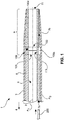
- Fig. 1 depicts a steerable medical device 1.
- the device 1 comprises an outer wall 3 and an inner wall 5 which is encompassed by the outer wall 3.
- the device 1 comprises a device body 2, a main lumen 6 and an eccentrically located ancillary lumen 7a, 7b.
- the device 1 comprises a proximal portion 4, and a distal end portion 9 terminated by a tip 11.
- a pull wire ring 100a according to a first embodiment is installed.
- the pull wire ring 100a comprises a first end face 101 facing away from the distal end portion 9 and a second end face 103 facing the distal end or tip 11 of the device 1.
- the pull wire ring 100a further comprises an outer peripheral surface 109 which abuts against the outer wall 3 of device 1.
- the pull wire ring 100a comprises an inner peripheral surface 111 which has a clearance which is preferably equal to or larger than the clearance of the main lumen 6.
- the pull wire ring 100a is oriented substantially coaxially with respect to axis A1.
- a recess 105a is formed in the outer peripheral surface 109 of pull wire ring 100a.
- Recess 105a defines a passage between the ring 100a and the wall of the device 1, said passage allowing transfer of an ancillary element 200 from ancillary lumen 7a through to ancillary lumen 7b.
- Ancillary lumen 7b is depicted in Fig. 1 as extending entirely through to the distal end or tip 11, but could within the scope of the invention terminate anywhere between the pull wire ring 100a and tip 11, depending on where the added functionality shall exactly be provided.
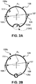
- the pull wire ring 100a shown in Fig. 1 is also depicted in a schematic cross-sectional view in Fig. 2A .
- the pull wire ring 100a further comprises fixation means 107 for attaching pull wires to the ring 100a.
- the fixation means 107 may comprise mechanical coupling means which allow an interlocking relationship between the pull wires and the pull wire ring 100a.
- the fixation means 107 may comprise a material portion which allows for permanently attaching the pull wires 108 to the pull wire ring 100a, such as by way of welding, soldering, knotting or gluing.
- recess 105a is formed as an indentation from the outer peripheral surface 109 inwards.
- a recess 105f could also be formed as an indentation from the inner peripheral surface 111 outwards, as indicated by the crossed lines in Fig. 2A .
- Fig. 2B depicts a variant of a pull wire ring 100b.
- the pull wire ring 100b could alternatively be used in the medical device 1 of Fig. 1 .
- the pull wire ring 100b comprises a recess in the form of a through-hole 105b.
- the through-hole 105b in the embodiment of Fig. 2B has a circular cross-section.
- different cross-sectional geometries are also within the scope of the invention, as is for example shown with respect to Fig. 3 (see below).
- pull wire rings 100a and 100b show ring geometries with closed circumferential surfaces
- Fig. 2C shows as a further variant a pull wire ring 100c with an open circumferential geometry.
- pull wire ring 100c comprises a gap 104c.
- the gap 104c extends from the outer peripheral surface 109 through to the inner peripheral surface 111 and creates an opening across an angle ⁇ .
- the pull wire ring 100c of Fig. 2C thus would have horseshoe geometry if it were not fully embedded in a support structure 110.
- Fig. 2C thus would have horseshoe geometry if it were not fully embedded in a support structure 110.
- the pull wire ring 100c comprises a support structure 110.
- An eccentric recess in the form of a through-hole 105c is preferably formed in and extends through the support structure 110.
- the gap 104c would constitute the eccentric recess which defines a passage for at least one ancillary element.
- Fig. 2D shows a segmented pull wire ring 100d.
- the segmented pull wire ring 100D comprises not one, but two gaps 104d, respectively extending from the outer peripheral surface 109 through to the inner peripheral surface 111.
- the gaps span over angles ⁇ and ⁇ , respectively.
- ⁇ is equal to ⁇ .
- the segments of the pull wire ring 100d are either fixed independently from each other to the inner walls of the device 1 of Fig. 1 , or, preferably and as shown in Fig. 2D , are embedded in the support structure 110 for increased stability.
- two eccentric recesses in the form of through-holes 105d are formed in and extend through the support structure 110.
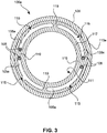
- Fig. 3 shows a further embodiment of a pull wire ring 100e in accordance with the invention.
- the pull wire ring 100e is shown with a support structure 110e, extending around a base body 117.
- the support structure 100e may be a shrink-fit tube or conventional polymer material according to one of the preferred embodiments described hereinabove and defines the outer peripheral surface 109.
- the pull wire ring 100e comprises a plurality of eccentric recesses 105e.
- the eccentric recesses 105e are formed inside the base body 117.
- the recesses 105e are to be considered as indentations respectively having an opening 115. Otherwise, the recesses 105e are to be considered as through-holes in terms of the invention.
- the pull wire ring 100e further comprises a plurality of ribs 119.
- the ribs 119 are adapted for holding pull wires 108.
- the pull wires 108 are bent around the ribs 119 as shown in figure 3 .
- the embodiment shown in figure 3 is particularly suited for use with polymeric pull wires, for example made of polyethylene or ultra-high-molecular-weight polyethylene (UHMW-PE).
- UHMW-PE ultra-high-molecular-weight polyethylene
- the embodiment is suited for use with Dyneema pull wires.
- the pull wires 108 may be inserted into the pull wire ring 100e through to the openings 115 when the pull wire ring 100e is used without support structure 110e, or prior to mounting the support structure 100e onto the base body 117.
- a steerable medical device has been generally described.
- a steerable catheter or sheath may be used as specific example of a steerable medical device.
- a single unit may fulfill the functions of several items recited in the claims.
- the mere fact that certain measures are recited in mutually different dependent claims does not indicate that a combination of these measures cannot be used to advantage.
Claims (11)
- Dispositif médical orientable (1), comprenant:un corps de dispositif (2), ledit corps de dispositif définissant un lumen principale (6),au moins un fil de traction (108) s'étendant depuis une partie d'extrémité proximale du dispositif vers une partie d'extrémité distale (9) du dispositif (1), etun anneau de fil de traction (100a-e) situé dans la partie d'extrémité distale du dispositif, ledit fil de traction étant attaché à l'anneau de fil de traction (100a-e) et adapté pour imprimer un mouvement de flexion au dispositif (1),où l'anneau de fil de traction (100a-e) comprend:une première face d'extrémité (101) et une seconde face d'extrémité (103) opposée à la première face d'extrémité,une surface périphérique externe (109) et une surface périphérique interne (111) s'étendant respectivement entre la première et la seconde face d'extrémité,des moyens de fixation (107) pour attacher au moins un fil de traction (108) à l'anneau, caractérisé en ce quel'anneau comprend en outre au moins un évidement excentrique (105a-e) s'étendant de la première face d'extrémité à la seconde face d'extrémité, ledit évidement définissant un passage pour au moins un élément auxiliaire (200) choisi dans le groupe des lignes électriques, des câbles de données et des fibres optiques; etle dispositif orientable (1) comprenant l'au moins un élément auxiliaire (200) s'étendant à travers l'évidement excentrique (105a-e) de l'anneau de fil de traction (100a-e) plus loin vers l'extrémité distale du dispositif (1).
- Dispositif médical orientable selon la revendication 1, dans lequel l'évidement est une indentation (105a) dans la surface périphérique externe (109) de l'anneau (100a, b).
- Dispositif médical orientable selon la revendication 1, dans lequel l'évidement est une indentation (105f) dans la surface périphérique interne (111) de l'anneau (100a).
- Dispositif médical orientable selon la revendication 1, dans lequel l'évidement de l'anneau (100a, c, d, e) est un trou traversant (105b, c, d, e) .
- Dispositif médical orientable selon la revendication 1, dans lequel l'évidement de l'anneau (100c) est un espace (104c) s'étendant de la surface périphérique externe (109) à la surface périphérique interne (111).
- Dispositif médical orientable selon la revendication 1, dans lequel l'anneau (100d, e) comprend:une pluralité d'évidements excentriques (105d, e), etun, plusieurs ou tous les évidements excentriques qui sont choisis dans le groupe constitué de:une indentation dans la surface périphérique externe (109) de l'anneau,une indentation dans la surface périphérique intérieure (111) de l'anneau,un trou traversant (105d, e),un espace s'étendant de la surface périphérique externe (109) à la surface périphérique interne (111).
- Dispositif médical orientable selon la revendication 1, comprenant une structure de support (110, 110d) qui est fixée à l'anneau (100c, d, e).
- Dispositif médical orientable selon la revendication 7, dans lequel la structure de support (110) encastre au moins partiellement l'anneau (100c, d) .
- Dispositif médical orientable selon la revendication 7, dans lequel l'au moins un évidement excentrique (105c, d) s'étend à travers la structure de support (110c, d) de l'anneau (100c, d).
- Dispositif médical orientable selon la revendication 7, dans lequel la structure de support (110, 110e) de l'anneau (100c, d, e) est constituée d'un matériau polymère ayant une dureté Shore de 50D ou plus.
- Dispositif médical orientable selon la revendication 7, dans lequel la structure de support de l'anneau (100c, d, e) est constituée d'au moins l'un des suivants:un élastomère,un thermoplastique,polyuréthane,polyéthylène,polychlorure de vinyle,amide-bloc de polyéther,polyétheréthercétone,polyamide,un polymère thermodurcissable,une gaine thermorétractable,éthylène propylène fluoré,polyester,ou des combinaisons de ceux-ci.
Applications Claiming Priority (2)
| Application Number | Priority Date | Filing Date | Title |
|---|---|---|---|
| EP14191734 | 2014-11-04 | ||
| PCT/EP2015/075660 WO2016071378A1 (fr) | 2014-11-04 | 2015-11-04 | Dispositif médical orientable, et utilisation d'un anneau de fil de traction en son sein |
Publications (2)
| Publication Number | Publication Date |
|---|---|
| EP3215210A1 EP3215210A1 (fr) | 2017-09-13 |
| EP3215210B1 true EP3215210B1 (fr) | 2021-10-13 |
Family
ID=51893856
Family Applications (1)
| Application Number | Title | Priority Date | Filing Date |
|---|---|---|---|
| EP15797618.4A Active EP3215210B1 (fr) | 2014-11-04 | 2015-11-04 | Dispositif médical orientable |
Country Status (5)
| Country | Link |
|---|---|
| US (1) | US10821265B2 (fr) |
| EP (1) | EP3215210B1 (fr) |
| JP (1) | JP6653698B2 (fr) |
| CN (1) | CN107148291B (fr) |
| WO (1) | WO2016071378A1 (fr) |
Families Citing this family (4)
| Publication number | Priority date | Publication date | Assignee | Title |
|---|---|---|---|---|
| WO2018060495A1 (fr) * | 2016-09-29 | 2018-04-05 | Koninklijke Philips N.V. | Couronne de fil de traction et manchon de couronne pour ensemble cathéter |
| WO2022272006A1 (fr) * | 2021-06-25 | 2022-12-29 | Wanliang Shan | Aiguilles robotiques orientables dotées de segments à rigidité réglable pour des manœuvres à courbure élevée |
| CN113491816B (zh) * | 2021-07-06 | 2023-06-27 | 上海康德莱医疗器械股份有限公司 | 一种电定位可控弯导丝 |
| CN117442846B (zh) * | 2023-12-22 | 2024-03-15 | 苏州汇禾医疗科技有限公司 | 一种拉线环 |
Family Cites Families (20)
| Publication number | Priority date | Publication date | Assignee | Title |
|---|---|---|---|---|
| US4911148A (en) | 1989-03-14 | 1990-03-27 | Intramed Laboratories, Inc. | Deflectable-end endoscope with detachable flexible shaft assembly |
| US5676653A (en) | 1995-06-27 | 1997-10-14 | Arrow International Investment Corp. | Kink-resistant steerable catheter assembly |
| US6374476B1 (en) * | 1999-03-03 | 2002-04-23 | Codris Webster, Inc. | Method for making a catheter tip section |
| US6926669B1 (en) * | 2000-10-10 | 2005-08-09 | Medtronic, Inc. | Heart wall ablation/mapping catheter and method |
| US7226410B2 (en) * | 2002-12-05 | 2007-06-05 | Ethicon-Endo Surgery, Inc. | Locally-propelled, intraluminal device with cable loop track and method of use |
| US7591813B2 (en) | 2003-10-01 | 2009-09-22 | Micrus Endovascular Corporation | Long nose manipulatable catheter |
| US7374553B2 (en) | 2004-06-24 | 2008-05-20 | Cryocor, Inc. | System for bi-directionally controlling the cryo-tip of a cryoablation catheter |
| JP3895755B2 (ja) * | 2005-07-04 | 2007-03-22 | テルモ株式会社 | 医療用チューブ |
| US20080234660A2 (en) * | 2006-05-16 | 2008-09-25 | Sarah Cumming | Steerable Catheter Using Flat Pull Wires and Method of Making Same |
| US8162934B2 (en) * | 2007-12-21 | 2012-04-24 | St. Jude Medical, Atrial Fibrillation Division, Inc. | Medical catheter assembly with deflection pull ring and distal tip interlock |
| US8226641B2 (en) | 2007-12-21 | 2012-07-24 | St. Jude Medical, Atrial Fibrillation Division, Inc. | Medical catheter with deflection pull ring and distal tip attachment apparatus |
| US8123721B2 (en) * | 2008-12-31 | 2012-02-28 | St. Jude Medical, Atrial Fibrillation Division, Inc. | Catheter having independently-deflectable segments and method of its manufacture |
| WO2013069019A2 (fr) * | 2011-11-08 | 2013-05-16 | Valtech Cardio, Ltd. | Fonction d'orientation commandée d'un outil de pose d'implant |
| JP4897077B1 (ja) * | 2010-09-28 | 2012-03-14 | 日本ライフライン株式会社 | カテーテル |
| US8702647B2 (en) | 2012-04-19 | 2014-04-22 | Medtronic Ablation Frontiers Llc | Catheter deflection anchor |
| US9949828B2 (en) | 2012-10-23 | 2018-04-24 | Valtech Cardio, Ltd. | Controlled steering functionality for implant-delivery tool |
| US20140148673A1 (en) | 2012-11-28 | 2014-05-29 | Hansen Medical, Inc. | Method of anchoring pullwire directly articulatable region in catheter |
| US9044156B2 (en) * | 2012-12-28 | 2015-06-02 | Biosense Webster (Israel) Ltd. | Catheter with improved safety line for distal tip and related method |
| US20140257130A1 (en) * | 2013-03-11 | 2014-09-11 | Boston Scientific Scimed, Inc. | Powered pull wire design for ablation catheters |
| CN103706017B (zh) * | 2013-12-27 | 2016-08-17 | 先健科技(深圳)有限公司 | 可调弯鞘管 |
-
2015
- 2015-11-04 US US15/523,963 patent/US10821265B2/en active Active
- 2015-11-04 CN CN201580059944.9A patent/CN107148291B/zh active Active
- 2015-11-04 EP EP15797618.4A patent/EP3215210B1/fr active Active
- 2015-11-04 JP JP2017522079A patent/JP6653698B2/ja active Active
- 2015-11-04 WO PCT/EP2015/075660 patent/WO2016071378A1/fr active Application Filing
Non-Patent Citations (1)
| Title |
|---|
| None * |
Also Published As
| Publication number | Publication date |
|---|---|
| US10821265B2 (en) | 2020-11-03 |
| WO2016071378A1 (fr) | 2016-05-12 |
| CN107148291A (zh) | 2017-09-08 |
| EP3215210A1 (fr) | 2017-09-13 |
| JP6653698B2 (ja) | 2020-02-26 |
| CN107148291B (zh) | 2021-10-12 |
| US20170361066A1 (en) | 2017-12-21 |
| JP2017536158A (ja) | 2017-12-07 |
Similar Documents
| Publication | Publication Date | Title |
|---|---|---|
| EP3215210B1 (fr) | Dispositif médical orientable | |
| EP3302215B1 (fr) | Endoscope | |
| US8794989B2 (en) | Modular driveline | |
| WO2006135755A3 (fr) | Dispositifs medicaux comportant des surfaces superhydrophobes, superhydrophiles ou les deux | |
| JP6133594B2 (ja) | 医療用チューブ及び可撓性可変機構 | |
| CN107249491A (zh) | 医疗用机械手 | |
| US9526862B2 (en) | Medical tube and flexibility-variable mechanism with the same | |
| DE602004003142D1 (en) | Infusionsgerät | |
| WO2011033783A1 (fr) | Cathéter | |
| JP2011062354A (ja) | カテーテル | |
| TW201438672A (zh) | 醫療機器 | |
| TW201438661A (zh) | 醫療機器 | |
| EP3009162B1 (fr) | Cathéter et procédé pour sa fabrication | |
| US20170266410A1 (en) | Multi-channel catheter insert | |
| JP2017536158A5 (fr) | ||
| US10493260B2 (en) | Rotating connector | |
| KR102208265B1 (ko) | 가이드와이어의 조향을 위한 마이크로로봇 | |
| US10406324B2 (en) | Actuating member and medical apparatus | |
| JP5901469B2 (ja) | 内視鏡 | |
| EP3546012B1 (fr) | Instrument médical | |
| US10036496B1 (en) | Fitting with a protrusion | |
| WO2014155488A1 (fr) | Cathéter intravasculaire d'aspiration de matière étrangère | |
| JP2015159971A (ja) | カテーテルおよびカテーテルの製造方法 |
Legal Events
| Date | Code | Title | Description |
|---|---|---|---|
| STAA | Information on the status of an ep patent application or granted ep patent |
Free format text: STATUS: THE INTERNATIONAL PUBLICATION HAS BEEN MADE |
|
| PUAI | Public reference made under article 153(3) epc to a published international application that has entered the european phase |
Free format text: ORIGINAL CODE: 0009012 |
|
| STAA | Information on the status of an ep patent application or granted ep patent |
Free format text: STATUS: REQUEST FOR EXAMINATION WAS MADE |
|
| 17P | Request for examination filed |
Effective date: 20170606 |
|
| AK | Designated contracting states |
Kind code of ref document: A1 Designated state(s): AL AT BE BG CH CY CZ DE DK EE ES FI FR GB GR HR HU IE IS IT LI LT LU LV MC MK MT NL NO PL PT RO RS SE SI SK SM TR |
|
| AX | Request for extension of the european patent |
Extension state: BA ME |
|
| DAV | Request for validation of the european patent (deleted) | ||
| DAX | Request for extension of the european patent (deleted) | ||
| STAA | Information on the status of an ep patent application or granted ep patent |
Free format text: STATUS: EXAMINATION IS IN PROGRESS |
|
| 17Q | First examination report despatched |
Effective date: 20191205 |
|
| RAP1 | Party data changed (applicant data changed or rights of an application transferred) |
Owner name: KONINKLIJKE PHILIPS N.V. |
|
| STAA | Information on the status of an ep patent application or granted ep patent |
Free format text: STATUS: EXAMINATION IS IN PROGRESS |
|
| GRAP | Despatch of communication of intention to grant a patent |
Free format text: ORIGINAL CODE: EPIDOSNIGR1 |
|
| STAA | Information on the status of an ep patent application or granted ep patent |
Free format text: STATUS: GRANT OF PATENT IS INTENDED |
|
| INTG | Intention to grant announced |
Effective date: 20210503 |
|
| GRAS | Grant fee paid |
Free format text: ORIGINAL CODE: EPIDOSNIGR3 |
|
| GRAA | (expected) grant |
Free format text: ORIGINAL CODE: 0009210 |
|
| STAA | Information on the status of an ep patent application or granted ep patent |
Free format text: STATUS: THE PATENT HAS BEEN GRANTED |
|
| AK | Designated contracting states |
Kind code of ref document: B1 Designated state(s): AL AT BE BG CH CY CZ DE DK EE ES FI FR GB GR HR HU IE IS IT LI LT LU LV MC MK MT NL NO PL PT RO RS SE SI SK SM TR |
|
| REG | Reference to a national code |
Ref country code: GB Ref legal event code: FG4D |
|
| REG | Reference to a national code |
Ref country code: CH Ref legal event code: EP |
|
| REG | Reference to a national code |
Ref country code: DE Ref legal event code: R096 Ref document number: 602015074127 Country of ref document: DE |
|
| REG | Reference to a national code |
Ref country code: IE Ref legal event code: FG4D |
|
| REG | Reference to a national code |
Ref country code: AT Ref legal event code: REF Ref document number: 1437705 Country of ref document: AT Kind code of ref document: T Effective date: 20211115 |
|
| REG | Reference to a national code |
Ref country code: LT Ref legal event code: MG9D |
|
| REG | Reference to a national code |
Ref country code: NL Ref legal event code: MP Effective date: 20211013 |
|
| REG | Reference to a national code |
Ref country code: AT Ref legal event code: MK05 Ref document number: 1437705 Country of ref document: AT Kind code of ref document: T Effective date: 20211013 |
|
| PG25 | Lapsed in a contracting state [announced via postgrant information from national office to epo] |
Ref country code: RS Free format text: LAPSE BECAUSE OF FAILURE TO SUBMIT A TRANSLATION OF THE DESCRIPTION OR TO PAY THE FEE WITHIN THE PRESCRIBED TIME-LIMIT Effective date: 20211013 Ref country code: LT Free format text: LAPSE BECAUSE OF FAILURE TO SUBMIT A TRANSLATION OF THE DESCRIPTION OR TO PAY THE FEE WITHIN THE PRESCRIBED TIME-LIMIT Effective date: 20211013 Ref country code: FI Free format text: LAPSE BECAUSE OF FAILURE TO SUBMIT A TRANSLATION OF THE DESCRIPTION OR TO PAY THE FEE WITHIN THE PRESCRIBED TIME-LIMIT Effective date: 20211013 Ref country code: BG Free format text: LAPSE BECAUSE OF FAILURE TO SUBMIT A TRANSLATION OF THE DESCRIPTION OR TO PAY THE FEE WITHIN THE PRESCRIBED TIME-LIMIT Effective date: 20220113 Ref country code: AT Free format text: LAPSE BECAUSE OF FAILURE TO SUBMIT A TRANSLATION OF THE DESCRIPTION OR TO PAY THE FEE WITHIN THE PRESCRIBED TIME-LIMIT Effective date: 20211013 |
|
| PG25 | Lapsed in a contracting state [announced via postgrant information from national office to epo] |
Ref country code: IS Free format text: LAPSE BECAUSE OF FAILURE TO SUBMIT A TRANSLATION OF THE DESCRIPTION OR TO PAY THE FEE WITHIN THE PRESCRIBED TIME-LIMIT Effective date: 20220213 Ref country code: SE Free format text: LAPSE BECAUSE OF FAILURE TO SUBMIT A TRANSLATION OF THE DESCRIPTION OR TO PAY THE FEE WITHIN THE PRESCRIBED TIME-LIMIT Effective date: 20211013 Ref country code: PT Free format text: LAPSE BECAUSE OF FAILURE TO SUBMIT A TRANSLATION OF THE DESCRIPTION OR TO PAY THE FEE WITHIN THE PRESCRIBED TIME-LIMIT Effective date: 20220214 Ref country code: PL Free format text: LAPSE BECAUSE OF FAILURE TO SUBMIT A TRANSLATION OF THE DESCRIPTION OR TO PAY THE FEE WITHIN THE PRESCRIBED TIME-LIMIT Effective date: 20211013 Ref country code: NO Free format text: LAPSE BECAUSE OF FAILURE TO SUBMIT A TRANSLATION OF THE DESCRIPTION OR TO PAY THE FEE WITHIN THE PRESCRIBED TIME-LIMIT Effective date: 20220113 Ref country code: NL Free format text: LAPSE BECAUSE OF FAILURE TO SUBMIT A TRANSLATION OF THE DESCRIPTION OR TO PAY THE FEE WITHIN THE PRESCRIBED TIME-LIMIT Effective date: 20211013 Ref country code: LV Free format text: LAPSE BECAUSE OF FAILURE TO SUBMIT A TRANSLATION OF THE DESCRIPTION OR TO PAY THE FEE WITHIN THE PRESCRIBED TIME-LIMIT Effective date: 20211013 Ref country code: HR Free format text: LAPSE BECAUSE OF FAILURE TO SUBMIT A TRANSLATION OF THE DESCRIPTION OR TO PAY THE FEE WITHIN THE PRESCRIBED TIME-LIMIT Effective date: 20211013 Ref country code: GR Free format text: LAPSE BECAUSE OF FAILURE TO SUBMIT A TRANSLATION OF THE DESCRIPTION OR TO PAY THE FEE WITHIN THE PRESCRIBED TIME-LIMIT Effective date: 20220114 Ref country code: ES Free format text: LAPSE BECAUSE OF FAILURE TO SUBMIT A TRANSLATION OF THE DESCRIPTION OR TO PAY THE FEE WITHIN THE PRESCRIBED TIME-LIMIT Effective date: 20211013 |
|
| REG | Reference to a national code |
Ref country code: DE Ref legal event code: R097 Ref document number: 602015074127 Country of ref document: DE |
|
| REG | Reference to a national code |
Ref country code: CH Ref legal event code: PL |
|
| PG25 | Lapsed in a contracting state [announced via postgrant information from national office to epo] |
Ref country code: SM Free format text: LAPSE BECAUSE OF FAILURE TO SUBMIT A TRANSLATION OF THE DESCRIPTION OR TO PAY THE FEE WITHIN THE PRESCRIBED TIME-LIMIT Effective date: 20211013 Ref country code: SK Free format text: LAPSE BECAUSE OF FAILURE TO SUBMIT A TRANSLATION OF THE DESCRIPTION OR TO PAY THE FEE WITHIN THE PRESCRIBED TIME-LIMIT Effective date: 20211013 Ref country code: RO Free format text: LAPSE BECAUSE OF FAILURE TO SUBMIT A TRANSLATION OF THE DESCRIPTION OR TO PAY THE FEE WITHIN THE PRESCRIBED TIME-LIMIT Effective date: 20211013 Ref country code: MC Free format text: LAPSE BECAUSE OF FAILURE TO SUBMIT A TRANSLATION OF THE DESCRIPTION OR TO PAY THE FEE WITHIN THE PRESCRIBED TIME-LIMIT Effective date: 20211013 Ref country code: LU Free format text: LAPSE BECAUSE OF NON-PAYMENT OF DUE FEES Effective date: 20211104 Ref country code: EE Free format text: LAPSE BECAUSE OF FAILURE TO SUBMIT A TRANSLATION OF THE DESCRIPTION OR TO PAY THE FEE WITHIN THE PRESCRIBED TIME-LIMIT Effective date: 20211013 Ref country code: DK Free format text: LAPSE BECAUSE OF FAILURE TO SUBMIT A TRANSLATION OF THE DESCRIPTION OR TO PAY THE FEE WITHIN THE PRESCRIBED TIME-LIMIT Effective date: 20211013 Ref country code: CZ Free format text: LAPSE BECAUSE OF FAILURE TO SUBMIT A TRANSLATION OF THE DESCRIPTION OR TO PAY THE FEE WITHIN THE PRESCRIBED TIME-LIMIT Effective date: 20211013 Ref country code: BE Free format text: LAPSE BECAUSE OF NON-PAYMENT OF DUE FEES Effective date: 20211130 |
|
| REG | Reference to a national code |
Ref country code: BE Ref legal event code: MM Effective date: 20211130 |
|
| PLBE | No opposition filed within time limit |
Free format text: ORIGINAL CODE: 0009261 |
|
| STAA | Information on the status of an ep patent application or granted ep patent |
Free format text: STATUS: NO OPPOSITION FILED WITHIN TIME LIMIT |
|
| 26N | No opposition filed |
Effective date: 20220714 |
|
| PG25 | Lapsed in a contracting state [announced via postgrant information from national office to epo] |
Ref country code: IE Free format text: LAPSE BECAUSE OF NON-PAYMENT OF DUE FEES Effective date: 20211104 Ref country code: AL Free format text: LAPSE BECAUSE OF FAILURE TO SUBMIT A TRANSLATION OF THE DESCRIPTION OR TO PAY THE FEE WITHIN THE PRESCRIBED TIME-LIMIT Effective date: 20211013 |
|
| PG25 | Lapsed in a contracting state [announced via postgrant information from national office to epo] |
Ref country code: SI Free format text: LAPSE BECAUSE OF FAILURE TO SUBMIT A TRANSLATION OF THE DESCRIPTION OR TO PAY THE FEE WITHIN THE PRESCRIBED TIME-LIMIT Effective date: 20211013 |
|
| PG25 | Lapsed in a contracting state [announced via postgrant information from national office to epo] |
Ref country code: IT Free format text: LAPSE BECAUSE OF FAILURE TO SUBMIT A TRANSLATION OF THE DESCRIPTION OR TO PAY THE FEE WITHIN THE PRESCRIBED TIME-LIMIT Effective date: 20211013 Ref country code: HU Free format text: LAPSE BECAUSE OF FAILURE TO SUBMIT A TRANSLATION OF THE DESCRIPTION OR TO PAY THE FEE WITHIN THE PRESCRIBED TIME-LIMIT; INVALID AB INITIO Effective date: 20151104 |
|
| PG25 | Lapsed in a contracting state [announced via postgrant information from national office to epo] |
Ref country code: CY Free format text: LAPSE BECAUSE OF FAILURE TO SUBMIT A TRANSLATION OF THE DESCRIPTION OR TO PAY THE FEE WITHIN THE PRESCRIBED TIME-LIMIT Effective date: 20211013 |
|
| PG25 | Lapsed in a contracting state [announced via postgrant information from national office to epo] |
Ref country code: LI Free format text: LAPSE BECAUSE OF NON-PAYMENT OF DUE FEES Effective date: 20220701 Ref country code: CH Free format text: LAPSE BECAUSE OF NON-PAYMENT OF DUE FEES Effective date: 20220701 |
|
| PGFP | Annual fee paid to national office [announced via postgrant information from national office to epo] |
Ref country code: GB Payment date: 20231121 Year of fee payment: 9 |
|
| PGFP | Annual fee paid to national office [announced via postgrant information from national office to epo] |
Ref country code: FR Payment date: 20231123 Year of fee payment: 9 Ref country code: DE Payment date: 20231127 Year of fee payment: 9 |