EP3214451A1 - Probenträger-handhabungsvorrichtung - Google Patents
Probenträger-handhabungsvorrichtung Download PDFInfo
- Publication number
- EP3214451A1 EP3214451A1 EP16158382.8A EP16158382A EP3214451A1 EP 3214451 A1 EP3214451 A1 EP 3214451A1 EP 16158382 A EP16158382 A EP 16158382A EP 3214451 A1 EP3214451 A1 EP 3214451A1
- Authority
- EP
- European Patent Office
- Prior art keywords
- sample carrier
- push
- pull
- handling device
- transport
- Prior art date
- Legal status (The legal status is an assumption and is not a legal conclusion. Google has not performed a legal analysis and makes no representation as to the accuracy of the status listed.)
- Withdrawn
Links
- 239000000523 sample Substances 0.000 claims description 105
- 239000006101 laboratory sample Substances 0.000 claims description 19
- 239000000969 carrier Substances 0.000 claims description 13
- 238000004026 adhesive bonding Methods 0.000 claims description 6
- 230000032258 transport Effects 0.000 description 40
- 230000008859 change Effects 0.000 description 3
- 238000000034 method Methods 0.000 description 3
- 230000004888 barrier function Effects 0.000 description 2
- 238000005516 engineering process Methods 0.000 description 2
- 230000007613 environmental effect Effects 0.000 description 2
- 230000008569 process Effects 0.000 description 2
- 230000001419 dependent effect Effects 0.000 description 1
- 229920002457 flexible plastic Polymers 0.000 description 1
- 230000005484 gravity Effects 0.000 description 1
- 230000003993 interaction Effects 0.000 description 1
- 238000004519 manufacturing process Methods 0.000 description 1
- 239000000463 material Substances 0.000 description 1
- 239000000376 reactant Substances 0.000 description 1
- 238000005070 sampling Methods 0.000 description 1
- 238000005476 soldering Methods 0.000 description 1
- 238000003466 welding Methods 0.000 description 1
Images


Classifications
-
- G—PHYSICS
- G01—MEASURING; TESTING
- G01N—INVESTIGATING OR ANALYSING MATERIALS BY DETERMINING THEIR CHEMICAL OR PHYSICAL PROPERTIES
- G01N35/00—Automatic analysis not limited to methods or materials provided for in any single one of groups G01N1/00 - G01N33/00; Handling materials therefor
- G01N35/02—Automatic analysis not limited to methods or materials provided for in any single one of groups G01N1/00 - G01N33/00; Handling materials therefor using a plurality of sample containers moved by a conveyor system past one or more treatment or analysis stations
- G01N35/021—Automatic analysis not limited to methods or materials provided for in any single one of groups G01N1/00 - G01N33/00; Handling materials therefor using a plurality of sample containers moved by a conveyor system past one or more treatment or analysis stations having a flexible chain, e.g. "cartridge belt", conveyor for reaction cells or cuvettes
-
- G—PHYSICS
- G01—MEASURING; TESTING
- G01N—INVESTIGATING OR ANALYSING MATERIALS BY DETERMINING THEIR CHEMICAL OR PHYSICAL PROPERTIES
- G01N35/00—Automatic analysis not limited to methods or materials provided for in any single one of groups G01N1/00 - G01N33/00; Handling materials therefor
- G01N35/02—Automatic analysis not limited to methods or materials provided for in any single one of groups G01N1/00 - G01N33/00; Handling materials therefor using a plurality of sample containers moved by a conveyor system past one or more treatment or analysis stations
- G01N35/04—Details of the conveyor system
- G01N2035/046—General conveyor features
- G01N2035/0462—Buffers [FIFO] or stacks [LIFO] for holding carriers between operations
-
- G—PHYSICS
- G01—MEASURING; TESTING
- G01N—INVESTIGATING OR ANALYSING MATERIALS BY DETERMINING THEIR CHEMICAL OR PHYSICAL PROPERTIES
- G01N35/00—Automatic analysis not limited to methods or materials provided for in any single one of groups G01N1/00 - G01N33/00; Handling materials therefor
- G01N35/02—Automatic analysis not limited to methods or materials provided for in any single one of groups G01N1/00 - G01N33/00; Handling materials therefor using a plurality of sample containers moved by a conveyor system past one or more treatment or analysis stations
- G01N35/04—Details of the conveyor system
- G01N2035/046—General conveyor features
- G01N2035/0467—Switching points ("aiguillages")
- G01N2035/047—Switching points ("aiguillages") diverging, e.g. sending carriers to different analysers
Definitions
- Embodiments of the invention refer to a handling device to manipulate sample carriers on a transport system for a diagnostics laboratory.
- US 8,252,233 discloses a sample-processing system that improves total system processing efficiency.
- WO 2011/138448 discloses a system for transporting containers between different stations, wherein the containers are accommodated in container carriers.
- WO 2008/133708 concerns a method and a device for removing high priority samples from a primary conveyor.
- WO 2013/072318 discloses a process station of devices for conveying biological product containers.
- An object of the invention is to handle sample carriers which transport sample containers for transporting samples in an efficient and reliable way. This is realized by the sample carrier handling device according to claim 1, the diagnostic laboratory transport system according to claim 10 and the diagnostics laboratory system according to claim 14.
- a first aspect of the present invention concerns a sample carrier handling devices for manipulating a sample carrier which is configured to carry a sample container.
- the sample container usually contains a sample which is obtained to be analyzed in a diagnostics laboratory. Also other samples, e.g. reactants or other materials used in the diagnostics laboratory can be transported by the sample carrier.
- the sample carrier handling device comprises a housing which is at least partially closed. The housing defines a circumferential surface of the sample carrier handling device.
- the sample carrier handling device further comprises a pull-push-element to pull, push or pull and push the sample carrier at least with an end-portion of the pull-push-element.
- the pull-push-element is arranged in the housing so that during a movement of the pull-push-element a central axis of the pull-push-element changes its direction while the end portion of the pull-push-element remains in a level of motion.
- the central axis of the pull-push-element is in particular defined as the axis of longitudinal elongation of the pull-push-element.
- sample handling carrier device can be realized as a compact device with a reliable interaction with the sample carrier.
- the end-portion of the pull-push-element defines an axis of motion in the level of movement and the end portion is movable out of the circumferential surface along the axis of motion a maximum distance l between a first position and a second position of the pull-push-element.
- the sample carrier handling device in the first position at least more than half of the pull-push-element is placed inside the circumferential surface and in the second position at least more than half of the pull-push-element protrudes out of the housing, i.e. the circumferential surface. If the dimension of the circumferential surface along the axis of motion is m, the ratio of l over m is in the range of 1.1 to 1080 or in particular in the range of 1.2 to 8 or in particular 1.4 to 5.
- the ratio of l over m is in the range of 2 to 10, 2 to 5 or 3 to 5.
- the end-portion is configured to interact with the sample carrier, e.g. the end-portion comprises a detachable fixation element to interact with the sample carrier to pull, push, or pull and push the sample carrier.
- the sample carrier comprises a corresponding fixation device, respectively.
- the detachable fixation element is a magnet, an electro-magnet, a movable hook, a suction-element, a snap, a gluing element, a hook-and-loop fastener element, and/or a contact surface configured to interact with the sample carrier.
- the end-portion comprises an abutting surface.
- the abutting surface has a surface of a half-cylinder.
- the fixation element is attached only to a partial surface of the abutting surface, so that during the movement of the pull-push-element the fixation element gets into contact with a sample carrier surface in particular its corresponding fixation element at the first or second position and detaches form the sample carrier surface at the second or first position respectively, because the surface of the half-cylinder roll off the surface of the sample carrier.
- the gluing element is arranged on the abutting surface of the pull-push-element.
- the handling device comprises a link motion to guide the pull-push-element during its motion.
- a guide bar of the motion link is either realized by the push-pull-element itself or the guide bar of the motion link is connected to the pull-push-element.
- a link motion in the meaning used here is an element which deflects the push-pull-element or even reels and unreels the pull-push-element.
- the pull-push-element is a flexible rod, e.g. in particular a chain or made out of flexible plastic, gum.
- Flexible means here that the rod can be deformed by the motion link but remains rigid or is supported when protruding out of the circumferential surface under usual environmental conditions appropriate to process a diagnostics laboratory.
- a driving unit is connected to the pull-push-element wherein the driving unit is connected with a wheel which is arranged to contact with the flexible rod to move the flexible rod in a guide bar of the link motion.
- the wheel could be a gear 28 with meshes with pull-push-element as a chain or the wheel has a profile wherein a ratio of a circumferential surface of the flexible rod gets in contact with.
- the pull-push-element is a rigid rod.
- Rigid means here that the rod does not change its shape under gravitational forces in usual environmental conditions.
- the rigid rod is connected at its other end portion with a vertical movable carriage and the motion link is connected to the rigid rod with a link block at a point of deviation of the rigid rod.
- Vertical means in particular here approximately perpendicular with respect to the axis of motion. "Approximately perpendicular" means for the following and the scope of this disclosure within a range of 80 to 100 degrees in particular 85 to 95 degrees.
- Another aspect of the invention is a diagnostics laboratory sample carrier transport system, comprising a transport device, a sample carrier and a sample carrier handling device as described above.
- a further aspect of the inventive diagnostics laboratory sample carrier transport system is that the transport device comprises a transport belt to carry the sample carrier.
- the sample carrier handling device is connected to the transport belt so that the sample carrier are movable perpendicular with respect to a direction of motion of the transport belt. This allows reliably loading and unloading of the sample carrier to and from the transport belt in a compact arrangement.
- Another aspect of the inventive diagnostics laboratory sample carrier transport system is that it comprises a further transport belt arranged in parallel or perpendicular to the transport belt, wherein the sample carrier handling device is connected to the transport belt so that the sample carrier are movable from the transport belt to the further transport belt and/or form the further transport belt to the transport belt.
- a further aspect of the inventive diagnostics laboratory sample carrier transport system is that the transport system comprises a transport surface supporting the transport carriers, wherein the sample carrier handling device is connected to the transport surface to push, pull, or push and pull the sample carrier onto or from the transport surface. This allows easy and reliable loading sample carriers with or without samples in the sample carriers onto and/or from the transport surface in a compact arrangement.
- a further aspect of the invention is a diagnostics laboratory system comprising a pre-analytic system, a post-analytic system and a analyzer system and a diagnostic laboratory sample carrier transport system according as described above.
- At least one sample carrier handling device is connected to the diagnostics laboratory sample carrier transport system so that the sample carrier handling device is configured to transfer sample carrier between at least two out of the list of
- sample carrier handling device This allows the easy, reliable transfer of sample carriers with or without samples from one device to another device of the diagnostic laboratory system.
- the different devices uses their proper transport system, so that the sample carrier can be transferred between different transport systems of the diagnostics laboratory system and the proper transport systems by the sample carrier handling device.
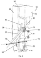
- FIGS 1 and 2 show a perspective view of one embodiment of a sample carrier handling device 10.
- the sample carrier handling device 10 comprises a housing 12.
- the housing 12 is assembled out of several parts. Some of these parts are shown in the figures. These parts are connected together by conventional connecting technologies such as screws, gluing, soldering, welding and/or other known technologies.
- the housing 12 has some open surface areas, i.e. the surface of the housing 12 is not totally closed.
- the outer surfaces of the parts of the housing 12 span a circumferential surface of the housing 12 which has approximately a shape of a cuboid.
- Some parts of the housing 12 shown in Fig. 1 are a first side wall 50, a middle wall 52, a front wall 54 and a second side wall 56.
- a portion of the second side wall 56 is bended to form a portion of a top surface. The edge of this bended portion abuts to an end portion of the middle wall 52.
- a front wall 54 is arranged between the second side wall 56 and the middle wall 52. The second side wall, the front wall 54 and the middle wall spans out a belt drive part of the housing 12 in which a belt drive 58 is arranged.
- the first side wall 50 is u-shaped facing with the edges of the arms of the u to the middle wall 52 so that a portion of the middle wall 52 and the first side wall 50 build up a frame.
- This frame defines a link-motion part of the housing.
- the pull-push-element is movably fixed.
- the pull-push-element is a rigid rod 32.
- An end portion 18 of the rigid rod 32 protrudes out of the circumferential surface.
- the other end portion of the rod 32 opposite to the end portion 18 is fixed to a carriage 34.
- the first side wall 50 is shorter than the middle wall 52 so that a rectangular recess is created.
- a driving unit 26 is arranged in this recess.
- a surface of the driving unit 26 fits at least partially into the cuboid-shaped circumferential surface of the housing 12.
- the driving unit 26 is connected to the belt drive 58 to move the belt drive 58 in both possible directions.
- the carriage 34 is arranged in a slit 53 of the middle wall so that it prolongs in the link-motion part and the belt-drive part of the housing 12.
- the carriage 34 In the belt drive part of the housing 12 the carriage 34 is fixed to the belt drive 58 so that the belt drive can move the carriage 34 in the slit 53 of the middle wall.
- the slit 53 defines the direction of motion of the carriage 34.
- the carriage In the link motion part the carriage comprises an acceptance to accept the other end portion of the rod 32, so that the end portion remains rotatable around a carriage axis. This carriage axis is arranged perpendicular to the elongation of the slit 53 in the middle wall.
- the carriage 34 comprises a distant portion 35 which engages with a sensor element 44 to detect an end-point of the movement of the carriage 34.
- This sensor element 44 is in particular a light barrier which will be interrupted by the distant portion.
- the rod 32 Adjacent to the other end portion of the rod 32 the rod 32 comprises two link blocks 36.
- the link blocks define an axis of deviation which is parallel to the carriage axis.
- the two link blocks engage into opposite guide bars 30 of the middle wall 52 and the side wall 50.
- the guide bars 30 and the link blocks 36 define a link motion.
- the guide bars can be designed as grooves in the wall or as slits.
- the carriage 34 moves the rod 32 in the link motion, so that the end portion 18 of the rod 32 moves along an axis of motion 16 which is in particular straight and perpendicular to the slit 53 in the middle wall.
- straight means herewith that the end portion 18 does not change its distance during its motion to a level of motion perpendicular to the slit 53 within a range of 0cm to 2cm In particular within a range of 0 to 1.5 cm, more in particular in a range of 0 to 1.0 cm or 0 to 0.5 cm.
- the end portion 18 can move a distance along the axis of motion 16 which is greater than the width of the housing 12 along the axis of motion.
- the guide bar 30 is curved so that the link motion provides that during movement of the carriage 34 the end portion 18 of the rigid rod 32 follows the axis of motion 16 within the accuracy of manufacturing possible.
- the carriage 34 At a first position of the rigid rod 32 within the housing the carriage 34 is moved to an upper position and the rigid rod mainly is placed inside the circumferential surface.
- the carriage 34 At a second position the carriage 34 is moved to a lower position.
- the distant portion of the carriage engages with the sensor element 44, i.e. interrupts the light barrier. This generates a signal to indicate that the carriage is at its lower position.
- the rigid rod 32 is at this second position protruding a maximum length l out of the circumferential surface.
- the dimension of the circumferential surface in the direction of the axis of motion 16 is m.
- the ratio of l over m is for this embodiment in the range of 1.2 to 3.
- the end portion 18 has a shape of half of a cylinder surface which its axis of rotation perpendicular to the central axis 20 of the rod 32.
- this cylindrical surface comprises a further element or elements configured to interact with the surface of a sample carrier getting in touch with the end portion 18.
- a magnet, an electro-magnet, a movable hook, a suction-element, a gluing element, a hook-and-loop fastener element, and/or a contact surface are arranged at the end portion 18 configured to interact with a correspondent element at the sample carrier surface, respectively.
- Fig. 3 and 4 presents a second embodiment of the sample carrier handling device 10.
- the pull-push-element is realized as a chain.
- the central axis 20 of the chain 24 is defined as the axis on which most of the elements of the chain 24 are aligned with.
- the chain 24 is guided in a guide bar 30 of a body 42 of the sample carrier handling device 10.
- the body 42 also defines a housing 12 which also realizes a circumferential surface.
- the body 42 comprises further a gear-wheel 28 arranged to mesh with the chain 24.
- a driving unit 26 is fixed to the body 42 and interacts with the gear wheel 28 to rotate the gear wheel 28.
- the guide bar deviates the chain 24 within the body 42 to perform a 90 degree change of movement. Therefore the central axis of the chain 24, as defined above changes its direction, during movement of the chain 24.
- An end portion of the chain 24 protrudes out of the body 42 to pull, push or push and pull the sample carrier along the axis of motion. Due to the deviation of the chain in the body 42 the maximum distance of motion of the end portion of the chain 24 is greater the dimension of the body 42 along the axis of motion 16.
- Either the sample handling carrier device 10 shown in this embodiment is arranged so that the chain elements block each other when they protrude out of the body 42. So the chain cannot be deviated by gravity in an unfortunate way.
- the chain 24 slips on a surface provided by the sample carrier transport system. The surface supports the chain element to avoid deviation.
- Fig. 3 the chain protrudes out of the body 42 at a maximum length l.
- the central axis 16 of the chain and the axis of motion 20 coincide.
- the body 42 i.e. the circumferential surface has a length m along the axis of motion 16.
- the ratio of l over m can be for this embodiment as high as 20 for a reasonable height of the body 42, which is the dimension perpendicular to the axis of motion 16.
- Fig. 4 the chain is completely within the body 42 and the central axis 20 of the chain 24 is perpendicular to the axis of motion 16 along which the end portion 18 of the chain 24 will move.
- the end portion of the chain comprises a further element or elements configured to interact with the surface of a sample carrier getting in touch with the end portion.
- a magnet, an electro-magnet, a movable hook, a suction-element, a gluing element, a hook-and-loop fastener element, and/or a contact surface are arranged at the end portion configured to interact with a correspondent element at the sample carrier surface, respectively.
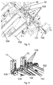
- FIG. 5 shows a detail of a view on a diagnostics laboratory sample carrier transport system.
- An incoming belt 102 transports sample carriers 108 with or without a sample containers 110 to an interconnecting belt 106.
- the incoming belt 102 pushes the sample carrier 108 onto the interconnecting belt 106.
- a sample carrier handling device 10 is arranged in front of the outgoing belt 104. This realizes a very compact reliable way to handle the sample carriers for connecting the incoming belt 102 and the outgoing belt 104.
- the interconnecting belt 106 is divided by protruding portions 107 into support sections adapted to receive one sample carrier 108.
- the protruding portions 107 are formed as a double ripple within the interconnecting belt 106.
- the sample carrier 108 comprises a cylindrical shaped base and elongated finger-elements. The end portion of the pull-push-element strikes against this surface of the cylindrical shaped base to move the sample carrier 108 from the interconnecting belt 106 to the outgoing belt 104.
- the elongated finger elements comprise flexible elements to support sample containers 110, which can then be transported within the sample carriers 108 on the transport system.
- Figure 6 shows another view on a bigger detail of the diagnostics laboratory sample carrier transport system shown in Figure 5 .
- a further incoming belt 102 and outgoing belt 104 are shown.
- Also here in front of the further outgoing belt a further sample carrier handling device 10 is placed.
- On the interconnecting belt 106 four sample carriers 108 are shown.
Priority Applications (4)
| Application Number | Priority Date | Filing Date | Title |
|---|---|---|---|
| EP16158382.8A EP3214451A1 (de) | 2016-03-03 | 2016-03-03 | Probenträger-handhabungsvorrichtung |
| US15/440,120 US10578631B2 (en) | 2016-03-03 | 2017-02-23 | Sample carrier handling device |
| JP2017036413A JP6929661B2 (ja) | 2016-03-03 | 2017-02-28 | 試料キャリアハンドリング装置 |
| CN201710120486.6A CN107153123B (zh) | 2016-03-03 | 2017-03-02 | 样本载体处理装置 |
Applications Claiming Priority (1)
| Application Number | Priority Date | Filing Date | Title |
|---|---|---|---|
| EP16158382.8A EP3214451A1 (de) | 2016-03-03 | 2016-03-03 | Probenträger-handhabungsvorrichtung |
Publications (1)
| Publication Number | Publication Date |
|---|---|
| EP3214451A1 true EP3214451A1 (de) | 2017-09-06 |
Family
ID=55456654
Family Applications (1)
| Application Number | Title | Priority Date | Filing Date |
|---|---|---|---|
| EP16158382.8A Withdrawn EP3214451A1 (de) | 2016-03-03 | 2016-03-03 | Probenträger-handhabungsvorrichtung |
Country Status (4)
| Country | Link |
|---|---|
| US (1) | US10578631B2 (de) |
| EP (1) | EP3214451A1 (de) |
| JP (1) | JP6929661B2 (de) |
| CN (1) | CN107153123B (de) |
Citations (7)
| Publication number | Priority date | Publication date | Assignee | Title |
|---|---|---|---|---|
| US6837359B1 (en) * | 2004-02-17 | 2005-01-04 | Dean E. Bessette | Push off diverter for sortation systems |
| WO2008133708A1 (en) | 2007-05-01 | 2008-11-06 | Siemens Healthcare Diagnostics Inc. | Programmable random access sample handler for use within an automated laboratory system |
| WO2011138448A1 (de) | 2010-05-07 | 2011-11-10 | Pvt Probenverteiltechnik Gmbh | System zum transportieren von behältern zwischen unterschiedlichen stationen sowie der behälterträger |
| US20120024661A1 (en) * | 2010-08-02 | 2012-02-02 | Wilson William H | High speed diverter for baggage conveyor |
| US8252233B2 (en) | 2007-12-25 | 2012-08-28 | Hitachi High-Technologies Corporation | Automatic analyzer and sample-processing system |
| WO2013072318A1 (en) | 2011-11-16 | 2013-05-23 | Inpeco Ip Ltd. | Process station of devices for conveying biological product containers |
| WO2015059620A1 (en) * | 2013-10-23 | 2015-04-30 | Inpeco Holding Ltd. | Apparatus for transferring specimens of biological material between laboratory automation systems placed at different heights |
Family Cites Families (13)
| Publication number | Priority date | Publication date | Assignee | Title |
|---|---|---|---|---|
| JPS5545328Y2 (de) * | 1975-02-13 | 1980-10-24 | ||
| US3978992A (en) * | 1975-07-02 | 1976-09-07 | International Business Machines Corporation | Positioning apparatus |
| JPS60173057U (ja) * | 1984-04-24 | 1985-11-16 | 出光興産株式会社 | 分光分析器の試料セル供給機構 |
| CA1321940C (en) * | 1987-05-02 | 1993-09-07 | Teruaki Itoh | Apparatus for distributing sample liquid |
| JPH0682566U (ja) * | 1993-05-10 | 1994-11-25 | 株式会社堀場製作所 | ワーク移送装置 |
| US6235244B1 (en) * | 1998-12-14 | 2001-05-22 | Matrix Technologies Corp. | Uniformly expandable multi-channel pipettor |
| JP2001039505A (ja) * | 1999-07-29 | 2001-02-13 | Itoki Crebio Corp | 荷物のプッシャー装置 |
| US6790412B2 (en) * | 2001-02-06 | 2004-09-14 | Beckman Coulter, Inc. | Bulk vessel feeder |
| US7258521B2 (en) * | 2005-05-31 | 2007-08-21 | Scriptpro Llc | Chain-driven robotic arm |
| ITMI20072254A1 (it) * | 2007-11-30 | 2009-06-01 | Dachi S R L | "impianto di identificazione, trasporto ed indirizzamento automatico di campioni di materiale biologico" |
| JP2012014787A (ja) * | 2010-06-30 | 2012-01-19 | Sony Corp | 記憶装置 |
| CN103975245A (zh) * | 2011-11-07 | 2014-08-06 | 贝克曼考尔特公司 | 用于试样输送系统的磁阻尼 |
| CN203259534U (zh) * | 2013-05-14 | 2013-10-30 | 株式会社东芝 | 存放传送装置和分析装置 |
-
2016
- 2016-03-03 EP EP16158382.8A patent/EP3214451A1/de not_active Withdrawn
-
2017
- 2017-02-23 US US15/440,120 patent/US10578631B2/en not_active Expired - Fee Related
- 2017-02-28 JP JP2017036413A patent/JP6929661B2/ja active Active
- 2017-03-02 CN CN201710120486.6A patent/CN107153123B/zh not_active Expired - Fee Related
Patent Citations (7)
| Publication number | Priority date | Publication date | Assignee | Title |
|---|---|---|---|---|
| US6837359B1 (en) * | 2004-02-17 | 2005-01-04 | Dean E. Bessette | Push off diverter for sortation systems |
| WO2008133708A1 (en) | 2007-05-01 | 2008-11-06 | Siemens Healthcare Diagnostics Inc. | Programmable random access sample handler for use within an automated laboratory system |
| US8252233B2 (en) | 2007-12-25 | 2012-08-28 | Hitachi High-Technologies Corporation | Automatic analyzer and sample-processing system |
| WO2011138448A1 (de) | 2010-05-07 | 2011-11-10 | Pvt Probenverteiltechnik Gmbh | System zum transportieren von behältern zwischen unterschiedlichen stationen sowie der behälterträger |
| US20120024661A1 (en) * | 2010-08-02 | 2012-02-02 | Wilson William H | High speed diverter for baggage conveyor |
| WO2013072318A1 (en) | 2011-11-16 | 2013-05-23 | Inpeco Ip Ltd. | Process station of devices for conveying biological product containers |
| WO2015059620A1 (en) * | 2013-10-23 | 2015-04-30 | Inpeco Holding Ltd. | Apparatus for transferring specimens of biological material between laboratory automation systems placed at different heights |
Also Published As
| Publication number | Publication date |
|---|---|
| JP6929661B2 (ja) | 2021-09-01 |
| CN107153123B (zh) | 2021-11-19 |
| JP2017161514A (ja) | 2017-09-14 |
| CN107153123A (zh) | 2017-09-12 |
| US10578631B2 (en) | 2020-03-03 |
| US20170254824A1 (en) | 2017-09-07 |
Similar Documents
| Publication | Publication Date | Title |
|---|---|---|
| JP6743204B2 (ja) | 容器ホルダの保管および供給 | |
| JP5993478B2 (ja) | 垂直方向の搬送デバイス、ラボラトリサンプル分配システム、およびラボラトリオートメーションシステム | |
| EP2074431B1 (de) | Probenbehälter-förderer mit sporneinheiten in automatischen laborsystemen | |
| EP1546680B1 (de) | Probenträgertransfervorrichtung für ein förderband | |
| EP3191224B1 (de) | Probenbehälterträgersatz für ein laborprobenverteilungssystem, laborprobenverteilungssystem und laborautomatisierungssystem | |
| EP2315036A1 (de) | Anordnung und Verfahren zum Handhaben von Prüfröhrchen im Laboratorium | |
| CN108351363B (zh) | 样品处理装置及用于样品处理的方法 | |
| KR20110019380A (ko) | 생체 시료 홀더를 파지하기에 적당한 클램프, 생체 시료 홀더 및 적당한 클램프로 구성되는 조립체, 그리고 처리 및/또는 분석 장치 | |
| JP7139253B2 (ja) | 検体キャリア | |
| KR20180103155A (ko) | 생물학적 액체 샘플용 용기의 지지체를 운반하기 위한 시스템 및 이러한 운반 시스템을 포함하는 자동 분석 시스템 | |
| EP3368907B1 (de) | Greiferfinger und greifer | |
| JP6740281B2 (ja) | ラボラトリ診断容器キャリアを輸送する搬送ライン用のスイッチ | |
| EP3041768B1 (de) | Verfahren und anordnung zur handhabung von reagenzgläsern | |
| EP3214451A1 (de) | Probenträger-handhabungsvorrichtung | |
| JP6957740B2 (ja) | 試料容器運搬装置、実験室試料分配システム、および実験室自動化システム | |
| EP3432004A1 (de) | Laborprobenverteilungssystem und laborautomatisierungssystem | |
| ITRM950292A1 (it) | Meccanismo per il rovesciamento di strisce di prova in un analizzatore automatico. | |
| CN114556109A (zh) | 受检体容器抓持装置和受检体输送装置、连接装置 | |
| ITRM950293A1 (it) | Mezzi per distinguere i lati corretti di strisce di prova per analizzatori automatici. |
Legal Events
| Date | Code | Title | Description |
|---|---|---|---|
| PUAI | Public reference made under article 153(3) epc to a published international application that has entered the european phase |
Free format text: ORIGINAL CODE: 0009012 |
|
| STAA | Information on the status of an ep patent application or granted ep patent |
Free format text: STATUS: THE APPLICATION HAS BEEN PUBLISHED |
|
| AK | Designated contracting states |
Kind code of ref document: A1 Designated state(s): AL AT BE BG CH CY CZ DE DK EE ES FI FR GB GR HR HU IE IS IT LI LT LU LV MC MK MT NL NO PL PT RO RS SE SI SK SM TR |
|
| AX | Request for extension of the european patent |
Extension state: BA ME |
|
| STAA | Information on the status of an ep patent application or granted ep patent |
Free format text: STATUS: REQUEST FOR EXAMINATION WAS MADE |
|
| 17P | Request for examination filed |
Effective date: 20180306 |
|
| RBV | Designated contracting states (corrected) |
Designated state(s): AL AT BE BG CH CY CZ DE DK EE ES FI FR GB GR HR HU IE IS IT LI LT LU LV MC MK MT NL NO PL PT RO RS SE SI SK SM TR |
|
| STAA | Information on the status of an ep patent application or granted ep patent |
Free format text: STATUS: EXAMINATION IS IN PROGRESS |
|
| 17Q | First examination report despatched |
Effective date: 20210428 |
|
| STAA | Information on the status of an ep patent application or granted ep patent |
Free format text: STATUS: EXAMINATION IS IN PROGRESS |
|
| GRAP | Despatch of communication of intention to grant a patent |
Free format text: ORIGINAL CODE: EPIDOSNIGR1 |
|
| STAA | Information on the status of an ep patent application or granted ep patent |
Free format text: STATUS: GRANT OF PATENT IS INTENDED |
|
| INTG | Intention to grant announced |
Effective date: 20230105 |
|
| STAA | Information on the status of an ep patent application or granted ep patent |
Free format text: STATUS: THE APPLICATION IS DEEMED TO BE WITHDRAWN |
|
| 18D | Application deemed to be withdrawn |
Effective date: 20230516 |