EP3213176B1 - Human interface device and method - Google Patents
Human interface device and method Download PDFInfo
- Publication number
- EP3213176B1 EP3213176B1 EP15787987.5A EP15787987A EP3213176B1 EP 3213176 B1 EP3213176 B1 EP 3213176B1 EP 15787987 A EP15787987 A EP 15787987A EP 3213176 B1 EP3213176 B1 EP 3213176B1
- Authority
- EP
- European Patent Office
- Prior art keywords
- angle
- movement
- circular
- center position
- positions
- Prior art date
- Legal status (The legal status is an assumption and is not a legal conclusion. Google has not performed a legal analysis and makes no representation as to the accuracy of the status listed.)
- Active
Links
Images


Classifications
-
- G—PHYSICS
- G06—COMPUTING OR CALCULATING; COUNTING
- G06F—ELECTRIC DIGITAL DATA PROCESSING
- G06F3/00—Input arrangements for transferring data to be processed into a form capable of being handled by the computer; Output arrangements for transferring data from processing unit to output unit, e.g. interface arrangements
- G06F3/01—Input arrangements or combined input and output arrangements for interaction between user and computer
- G06F3/03—Arrangements for converting the position or the displacement of a member into a coded form
- G06F3/041—Digitisers, e.g. for touch screens or touch pads, characterised by the transducing means
- G06F3/0416—Control or interface arrangements specially adapted for digitisers
- G06F3/04166—Details of scanning methods, e.g. sampling time, grouping of sub areas or time sharing with display driving
-
- G—PHYSICS
- G06—COMPUTING OR CALCULATING; COUNTING
- G06F—ELECTRIC DIGITAL DATA PROCESSING
- G06F3/00—Input arrangements for transferring data to be processed into a form capable of being handled by the computer; Output arrangements for transferring data from processing unit to output unit, e.g. interface arrangements
- G06F3/01—Input arrangements or combined input and output arrangements for interaction between user and computer
- G06F3/017—Gesture based interaction, e.g. based on a set of recognized hand gestures
-
- G—PHYSICS
- G06—COMPUTING OR CALCULATING; COUNTING
- G06F—ELECTRIC DIGITAL DATA PROCESSING
- G06F3/00—Input arrangements for transferring data to be processed into a form capable of being handled by the computer; Output arrangements for transferring data from processing unit to output unit, e.g. interface arrangements
- G06F3/01—Input arrangements or combined input and output arrangements for interaction between user and computer
- G06F3/03—Arrangements for converting the position or the displacement of a member into a coded form
- G06F3/041—Digitisers, e.g. for touch screens or touch pads, characterised by the transducing means
- G06F3/0416—Control or interface arrangements specially adapted for digitisers
-
- G—PHYSICS
- G06—COMPUTING OR CALCULATING; COUNTING
- G06F—ELECTRIC DIGITAL DATA PROCESSING
- G06F3/00—Input arrangements for transferring data to be processed into a form capable of being handled by the computer; Output arrangements for transferring data from processing unit to output unit, e.g. interface arrangements
- G06F3/01—Input arrangements or combined input and output arrangements for interaction between user and computer
- G06F3/03—Arrangements for converting the position or the displacement of a member into a coded form
- G06F3/041—Digitisers, e.g. for touch screens or touch pads, characterised by the transducing means
- G06F3/044—Digitisers, e.g. for touch screens or touch pads, characterised by the transducing means by capacitive means
-
- G—PHYSICS
- G06—COMPUTING OR CALCULATING; COUNTING
- G06F—ELECTRIC DIGITAL DATA PROCESSING
- G06F3/00—Input arrangements for transferring data to be processed into a form capable of being handled by the computer; Output arrangements for transferring data from processing unit to output unit, e.g. interface arrangements
- G06F3/01—Input arrangements or combined input and output arrangements for interaction between user and computer
- G06F3/048—Interaction techniques based on graphical user interfaces [GUI]
- G06F3/0487—Interaction techniques based on graphical user interfaces [GUI] using specific features provided by the input device, e.g. functions controlled by the rotation of a mouse with dual sensing arrangements, or of the nature of the input device, e.g. tap gestures based on pressure sensed by a digitiser
- G06F3/0488—Interaction techniques based on graphical user interfaces [GUI] using specific features provided by the input device, e.g. functions controlled by the rotation of a mouse with dual sensing arrangements, or of the nature of the input device, e.g. tap gestures based on pressure sensed by a digitiser using a touch-screen or digitiser, e.g. input of commands through traced gestures
- G06F3/04883—Interaction techniques based on graphical user interfaces [GUI] using specific features provided by the input device, e.g. functions controlled by the rotation of a mouse with dual sensing arrangements, or of the nature of the input device, e.g. tap gestures based on pressure sensed by a digitiser using a touch-screen or digitiser, e.g. input of commands through traced gestures for inputting data by handwriting, e.g. gesture or text
Definitions
- the present disclosure relates to a method and device for a human interface, in particular a continuous circular gesture detection method for a sensor system.
- US Patent Application Publication US 2011/0205175 discloses a method and device for determining rotation gestures.
- International Application WO 2014/132893 discloses an operation detection device.
- a circle gesture is to be understood in this disclosure to mean any type of circular movement. It does not require to have a constant radius but the radius and center point may vary over time as typical for any free movement of a hand or finger describing a circle without having a reference point or a prescribed path to follow.
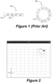
- a 1D capacitive slider 100 as for example shown in Figure 1 , comprises a plurality of linearly arranged sensor elements 110, 120. Such a sensor can also be arranged in a circle as shown with sensor 200 in Fig. 1 , in order to detect circular movement, certain MP3 music players use this technology.
- Fix Center Position Any point in 2D Cartesian coordinates can be bijectively mapped to a distance from a fixed reference position (center point) and the angle between a line through this point and the reference position and a reference direction vector, e.g. the direction of the positive x-axis, yielding the point in polar coordinates.
- the named angle is the desired 1D data.
- Atan2 Compared to the single-argument inverse tangent function whose output is periodic with ⁇ , atan2 additionally evaluates the signs of p(new,x)-p(c,x) and p(new,y)-p(c,y) and hence can map ⁇ to one of the four quadrants.
- this method is not restricted to input positions on a circle, but can take any 2D position as input and will output an angle.
- two output angles can be computed, their difference being a measure for the movement of the input position.
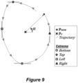
- a velocity vector at angle ⁇ to the top right can either origin from a position in quadrant II rotating clockwise - corresponding to angle ⁇ 1 of this position - or it can origin from a position rotating counter-clockwise in quadrant IV, corresponding to angle ⁇ 2 , where ⁇ 1 and ⁇ 2 differ by ⁇ .
- a map from ⁇ to ⁇ would imply jumps by ⁇ whenever the rotating direction changes - which is certainly not a smooth measure.
- Figure 6 shows the trajectory of an upward movement, first rotating clockwise and then changing the rotating direction.
- a circular gesture (rotational finger movement, hereinafter also called “AirWheel”) can be used in a gesture detection system to control a variety of different parameter, e.g. volume or light dimming control, etc..
- movements in a non-touching system are often not consistent and may be difficult to detect which can often lead to a bad user experience.
- the various embodiments of detection methods disclosed in this application are designed to overcome this possible disadvantage.
- a non-touching gesture detection system is shown in Fig. 15 .
- Such a three-dimensional gesture detection systems uses a quasi-static alternating electric field with a 4-frame receiving electrode layout.
- a transmitting electrode (not shown) may be, for example arranged under these four electrodes 1510, 1520, 1530, and 1540 and cover the entire area of or encircled by the receiving electrodes 1510, 1520, 1530, and 1540. Other arrangements may be used.
- the velocity vectors v k as shown in Fig.
- a transmission electrode (not shown) is used to generate an electric field, for example using a 30-200 kHz square wave signal generated by a microcontroller port, and the plurality of receiving electrodes 1510, 1520, 1530, and 1540 which detect a disturbance in the field when an object enters the quasi-static electric field.
- the signals from the receiving electrodes are fed to an evaluation device which is configured to determine a three-dimensional position from these signals.
- the transmission signal for generating the quasi static field is typically continuously fed to the transmitting electrode during a measurement, contrary to capacitive touch measurements which typically may use pulses.
- the method discussed herein may be particularly beneficial in such a three-dimensional non-touch gesture detection system. Further, gesture detection samples where the data from all electrodes 1510, 1520, 1530, and 1540 have the same sign, i.e. the finger is approaching/leaving all electrodes, may be ignored for updating the circle counter. However, as mentioned above, the method may apply to various other two- or three dimensional gesture detection systems.
- a gesture detection system determines a movement of an object, for example a finger between a start and stop event. For purposes of detecting a circular movement of the object, during the start and stop event a plurality of position measurement may be made and the positions may be converted into x-y coordinates of a two-dimensional coordinate system even if the system is capable of detecting three-dimensional positions.
- the sampling time may be preferably 200 samples per second and the system can determine vector values from the determined position values and from the associated sampling times.
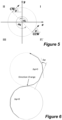
- Figure 2 shows a trace of a 2D position estimate for circular hand movement in front of a near field gesture detection using an electrode arrangement as shown in Fig. 15 .
- Figure 2 shows the trace of a 2D position estimate of a circular finger movement in front of a near-field gesture detection system in x- and y-direction.
- the positions are shown in the top right part of the detection area.
- the estimated position may also lie in another part of the detection area, e.g. in the bottom left, or the size of the detected trace is larger or smaller depending on an individual's shape of finger or hand.
- this movement shall still be detected as circular movement.
- Another reason for different positioning results can be that a default parameter set is used for a multitude of sensors, e.g. differing in size, and there shall be no need for the customer to re-parameterize the system, but functionality shall be provided out-of-the-box.
- a circular movement of a touching finger on the translucent cover plate of a light switch shall illuminate one LED of a set of LEDs arranged in a circle underneath the cover, whereas the lightened LED shall be the one placed at the position or at the angle corresponding to the finger's current position, i.e. the illumination follows the finger's position on a virtual circle.
- a circular movement can be detected by evaluating the rotating direction of input positions, and a virtual circle center is updated depending on the history of input positions, serving as a reference for output angle computation.
- the core of this disclosure is to update a virtual circle's center position - relative to which an angle of a position is computed - depending on the input positions' history. Two approaches are proposed.
- the center position is updated by combining several characteristic positions along a circular trajectory, e.g. by averaging). These positions are stored in a buffer where each of the buffer entries corresponds to a specific characteristic position along the circular trajectory.
- a possible set of characteristic positions are the local extrema in X or Y coordinates, as shown in Figure 9 . Each time a characteristic position is detected, first the corresponding entry in the buffer is updated with this position and then the center position. This is illustrated in Figure 9 .
- the extrema may be updated during each full circle movement performed by an object such as a finger or a hand.
- the value of the new extremum can be both, larger or smaller
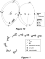
- Figure 10 illustrates this process, with four extrema, for a trajectory where the virtual center point changes position and the rotation changes direction, starting with clockwise rotation.
- the numbering indicates the time instances in the sequence where the extrema positions are detected and stored in the buffer and in which p c is updated.
- the crosses indicate the changing position of the circle center position. As can be seen, the most left position changes from point 2 to point 6 to point 11. The most top position changes from point 3 to point 7 to point 10. The most right position changes from point 4 to point 9 and the most bottom position from point 1 to point 5 to point 8.
- the update does only take place at the named time instances if a new input position p new is classified as being part of a circular movement and if the velocity ⁇ ⁇ new ⁇ is high enough, e.g. higher than a threshold.
- the angle of ⁇ new is continuously changing and due to the filtering delay, there is an angular difference between the two vectors. If the movement is non-circular, but rather linear, the direction of ⁇ new hardly changes over time and
- can be used as a continuous measure of the likelihood that the sample belongs to a circular movement or it can be compared with a fixed threshold for binary classification.
- Figure 11 illustrates an example of the circular classification process where the trajectory is changing from a circular to, for example, linear and where the decrease of the angular separation between ⁇ new and lp ⁇ is visible.
- Direction validation is a feature to prevent inversions of direction due to such fast position shifts.
- the movement In a real direction change, the movement typically first decelerates and then inverts the rotating direction.
- the output angle which is caused by erroneous estimation of the center position
- the movement typically does hardly decelerate.
- the output angle is not smooth, as the center position is changed abruptly, but with filtering, the effects of erroneous center estimation can be successfully mitigated.
- the center position is updated when the distance between a new position and the center point is smaller than the distance between a previous position and the center point, i.e. when the circle's radius is decreased in an update step.
- the center position p c is updated if the radius of the virtual circle is decreased, i.e. if the center position's distance (Euclidean distance) r new to the current input position p new is smaller than its distance r old to the former input position p old .
- This is illustrated in Figure 7 .
- the intersection point p IS of the perpendicular bisector PB of the line between current input position p new and previous input position p old with the line through p c and p old lies between p c and p old .
- Output values may be generated between a start and a stop event.
- a start event may be defined by a circular trajectory and when for example a predefined threshold angle has been exceeded.
- An angle may be accumulated over multiple measurement points and a start event generated when the threshold has been exceeded.
- start criteria may apply. Particularly, for 3D touchless sensor systems, the start can be triggered once movement is detected.
- the algorithm considers every new input position to compute the absolute angle ⁇ and, if it is found to be an extremum, to update the virtual center position p c . Outputs are only reported if the start conditions are met.
- This rotation angle is a simple accumulation of the angular changes between successive ⁇ since the first two input positions, or for a certain amount of time.
- Circular trajectory classification uses the circular movement classification (described above) to fill a buffer, preferably a first-in-first-out buffer of limited length.
- the likelihood that a trajectory is circular is obtained by averaging the classifications stored in the buffer, e.g. with a binary movement classification, it is defined as the number of buffer entries indicating circular movement over the total buffer length.
- the trajectory is considered as circular if the likelihood is above a predefined threshold.
- AirWheel can do volume control, and when starting at the right edge AirWheel can control a display's brightness.
- Possible stop detection techniques include the detection of the release of a touch, or the detection of a non-moving finger for a certain amount of time, or the removal of the finger/hand detected by other means than the release of a touch, e.g. hand removal from a 3D sensor system.
- a stop can also be detected if the trajectory ceases to be circular, i.e. if the likelihood of a circular trajectory becomes lower than a defined threshold.
- Start and/or stop detection can also be triggered by external means, e.g. by pressing/releasing a button of a keyboard.
- Listing 1 sketches the resulting algorithm of Approach A with four extrema points.
- the invers tangent function is approximated by linear segments. As the function is pointsymmetric around the origin, it is sufficient to approximate the function for positive values y and x only, i.e. for the first quadrant or quarter circle, and to change the sign of the output angle and/or add multiples of ⁇ depending on the signs of y and x. This is illustrated in Figure 14 where the segment borders are (y/x) ⁇ ⁇ 0,1,4,20 ⁇ , leading to a maximum error of ⁇ /22 on the output angle.
- each quadrant when segmenting a full circle into 16 segments of equal size with the x and y axis representing segment borders, each quadrant contains four segments.
- these threshold values are rather close to powers of two, they can be approximated by m ⁇ k ⁇ ⁇ 0.5, 1, 2 ⁇ , and comparisons of the kind y x ⁇ m ⁇ k ⁇ y ⁇ x ⁇ m ⁇ k can be further simplified by replacing the multiplication with m ⁇ k by bit shift operations.
- an artificial, fix center position could be introduced, e.g. in the touch pad's geometric center, and the estimated/detected finger position could be considered relative to this center position, yielding a unique angle (e.g. to the positive x-axis).
- a drawback of such an implementation could be that proper functionality is only provided when the selected center position is within the drawn circle. Thus for example a small circle drawn in the upper right corner of the touch pad may not be recognized.
- the method discussed above can be implemented into a wide variety of devices.
- the circular gesture may be used to resemble the control of a virtual Volume control wheel of a HiFi set: Clockwise movement increases the volume, counter-clockwise movement decreases the volume.
- any type of media-player control functionality known from, for example, a circular touchpad can be implemented.
- control of a dimmer in a light switch or various other appliance functions such as, for example, speed control, air condition temperature, mechanical movement functions, etc. can be implemented by the methods disclosed in this application.
- a replacement for a PC mouse's scroll wheel can be implemented.
- the various methods discussed above can be used with a wide variety of sensor systems. Examples for such sensor/measurement systems with two-dimensional sensor are touch panels / touch displays, 2D video cameras, etc..
- the disclosed methods may be used with 3D video cameras, 3D capacitive sensor systems, etc., where the 3D position is transformed into a 2D position, e.g. by omitting one dimension.
Landscapes
- Engineering & Computer Science (AREA)
- General Engineering & Computer Science (AREA)
- Theoretical Computer Science (AREA)
- Human Computer Interaction (AREA)
- Physics & Mathematics (AREA)
- General Physics & Mathematics (AREA)
- User Interface Of Digital Computer (AREA)
- Position Input By Displaying (AREA)
Applications Claiming Priority (3)
| Application Number | Priority Date | Filing Date | Title |
|---|---|---|---|
| US201462072184P | 2014-10-29 | 2014-10-29 | |
| US14/924,329 US9971442B2 (en) | 2014-10-29 | 2015-10-27 | Human interface device and method |
| PCT/EP2015/075040 WO2016066717A1 (en) | 2014-10-29 | 2015-10-28 | Human interface device and method |
Publications (2)
| Publication Number | Publication Date |
|---|---|
| EP3213176A1 EP3213176A1 (en) | 2017-09-06 |
| EP3213176B1 true EP3213176B1 (en) | 2024-09-04 |
Family
ID=55852645
Family Applications (1)
| Application Number | Title | Priority Date | Filing Date |
|---|---|---|---|
| EP15787987.5A Active EP3213176B1 (en) | 2014-10-29 | 2015-10-28 | Human interface device and method |
Country Status (7)
Families Citing this family (8)
| Publication number | Priority date | Publication date | Assignee | Title |
|---|---|---|---|---|
| US20050134578A1 (en) * | 2001-07-13 | 2005-06-23 | Universal Electronics Inc. | System and methods for interacting with a control environment |
| US10444892B2 (en) * | 2015-10-07 | 2019-10-15 | Microchip Technology Incorporated | Capacitance measurement device with reduced noise |
| US9910586B2 (en) * | 2016-03-03 | 2018-03-06 | Lenovo (Singapore) Pte. Ltd. | Apparatus, method, and program product for detecting input gestures |
| JP6729338B2 (ja) * | 2016-12-13 | 2020-07-22 | ヤマハ株式会社 | 表示装置 |
| US10551945B2 (en) * | 2017-03-02 | 2020-02-04 | Texas Instruments Incorporated | Touch slider-position sensing |
| JP7170312B2 (ja) * | 2018-09-12 | 2022-11-14 | 国立大学法人 東京大学 | プログラム、情報処理装置、及び情報処理方法 |
| US11370415B2 (en) * | 2019-11-25 | 2022-06-28 | Ford Global Technologies, Llc | Systems and methods for adaptive user input boundary support for remote vehicle motion commands |
| DE102022102295A1 (de) | 2022-02-01 | 2023-08-03 | epitome GmbH | Verfahren zum Steuern einer Reinigungsvorrichtung |
Family Cites Families (15)
| Publication number | Priority date | Publication date | Assignee | Title |
|---|---|---|---|---|
| JP3301079B2 (ja) * | 1990-06-18 | 2002-07-15 | ソニー株式会社 | 情報入力装置、情報入力方法、情報処理装置及び情報処理方法 |
| CN101390034B (zh) | 2004-01-29 | 2012-03-14 | 辛纳普蒂克斯有限公司 | 采用二维定位设备产生一维信号的方法及装置 |
| TWI430141B (zh) | 2010-02-25 | 2014-03-11 | Egalax Empia Technology Inc | 判斷旋轉手勢的方法與裝置 |
| US8754858B2 (en) * | 2010-09-07 | 2014-06-17 | STMicroelectronics Aisa Pacific Pte | Method to parameterize and recognize circular gestures on touch sensitive surfaces |
| TWI455002B (zh) * | 2011-02-01 | 2014-10-01 | Edamak Corp | 近接手勢偵測裝置及方法 |
| CN102368290B (zh) * | 2011-09-02 | 2012-12-26 | 华南理工大学 | 一种基于手指高级特征的手势识别方法 |
| CN103365456A (zh) * | 2012-04-09 | 2013-10-23 | 宏碁股份有限公司 | 手势操作方法 |
| CN103677555B (zh) * | 2012-09-18 | 2018-09-04 | 南京中兴软件有限责任公司 | 一种屏幕图像显示方法和装置 |
| KR102090269B1 (ko) * | 2012-12-14 | 2020-03-17 | 삼성전자주식회사 | 정보 검색 방법, 그와 같은 기능을 갖는 디바이스 및 기록 매체 |
| CN103970328B (zh) * | 2013-02-05 | 2016-12-28 | 株式会社理光 | 触摸式或非触摸式的多输入点控制指令检测方法和装置 |
| JP6142564B2 (ja) * | 2013-02-18 | 2017-06-07 | コニカミノルタ株式会社 | 情報表示装置および表示制御プログラム |
| WO2014132893A1 (ja) | 2013-02-27 | 2014-09-04 | アルプス電気株式会社 | 操作検知装置 |
| JP2014174801A (ja) * | 2013-03-11 | 2014-09-22 | Sony Corp | 情報処理装置、情報処理方法、及びプログラム |
| KR102091028B1 (ko) * | 2013-03-14 | 2020-04-14 | 삼성전자 주식회사 | 사용자 기기의 오브젝트 운용 방법 및 장치 |
| US9665204B2 (en) * | 2013-10-04 | 2017-05-30 | Microchip Technology Incorporated | Continuous circle gesture detection for a sensor system |
-
2015
- 2015-10-27 US US14/924,329 patent/US9971442B2/en active Active
- 2015-10-28 EP EP15787987.5A patent/EP3213176B1/en active Active
- 2015-10-28 JP JP2017523506A patent/JP6517932B2/ja active Active
- 2015-10-28 KR KR1020177011605A patent/KR102398042B1/ko active Active
- 2015-10-28 CN CN201580057661.0A patent/CN107077294B/zh active Active
- 2015-10-28 WO PCT/EP2015/075040 patent/WO2016066717A1/en active Application Filing
- 2015-10-29 TW TW104135650A patent/TWI703471B/zh active
Also Published As
| Publication number | Publication date |
|---|---|
| CN107077294A (zh) | 2017-08-18 |
| JP6517932B2 (ja) | 2019-05-22 |
| JP2017537387A (ja) | 2017-12-14 |
| TW201633065A (zh) | 2016-09-16 |
| KR102398042B1 (ko) | 2022-05-13 |
| EP3213176A1 (en) | 2017-09-06 |
| TWI703471B (zh) | 2020-09-01 |
| US9971442B2 (en) | 2018-05-15 |
| CN107077294B (zh) | 2020-08-07 |
| US20160124568A1 (en) | 2016-05-05 |
| WO2016066717A1 (en) | 2016-05-06 |
| KR20170104988A (ko) | 2017-09-18 |
Similar Documents
| Publication | Publication Date | Title |
|---|---|---|
| EP3213176B1 (en) | Human interface device and method | |
| EP3825824B1 (en) | Continuous circle gesture detection for a sensor system | |
| CN104123046B (zh) | 用于触控系统判断触控手势的方法及触控系统 | |
| US10365722B2 (en) | Human interface device and method | |
| US20150355740A1 (en) | Touch panel system | |
| WO2015104257A1 (en) | Human-to-computer natural three-dimensional hand gesture based navigation method | |
| US10366281B2 (en) | Gesture identification with natural images | |
| WO2014106219A1 (en) | User centric interface for interaction with visual display that recognizes user intentions | |
| JP2013525891A (ja) | ユーザのタッチジェスチャを判別する方法及びデバイス | |
| CN107817925B (zh) | 电容式触摸板基线值调整方法 | |
| KR102329097B1 (ko) | 용량형 센서 시스템에서의 터치 검출 | |
| CN113126801B (zh) | 侦测元件是否处在导电液体当中的方法与电子装置 | |
| EP4400953A1 (en) | Pointer candidates for touchless user interface control | |
| CN103778405A (zh) | 以自然影像进行的手势辨识方法 | |
| CN113126800B (zh) | 用于触控面板半浸入导电液体时的触控处理装置方法 | |
| JP2024081202A (ja) | 入力表示装置 | |
| TWI611343B (zh) | 觸控螢幕的操作方法及使用此操作方法的顯示模組 | |
| Na et al. | A Real-Time Hand Pose Recognition Method with Hidden Finger Prediction | |
| KR20030006667A (ko) | 복수 층, 접촉패턴 인식 터치 패드와 복수의 회전 측정 휠마우스 | |
| KR20140097907A (ko) | 카메라 기반 명령 입력 장치 및 그 방법 |
Legal Events
| Date | Code | Title | Description |
|---|---|---|---|
| STAA | Information on the status of an ep patent application or granted ep patent |
Free format text: STATUS: THE INTERNATIONAL PUBLICATION HAS BEEN MADE |
|
| PUAI | Public reference made under article 153(3) epc to a published international application that has entered the european phase |
Free format text: ORIGINAL CODE: 0009012 |
|
| STAA | Information on the status of an ep patent application or granted ep patent |
Free format text: STATUS: REQUEST FOR EXAMINATION WAS MADE |
|
| 17P | Request for examination filed |
Effective date: 20170526 |
|
| AK | Designated contracting states |
Kind code of ref document: A1 Designated state(s): AL AT BE BG CH CY CZ DE DK EE ES FI FR GB GR HR HU IE IS IT LI LT LU LV MC MK MT NL NO PL PT RO RS SE SI SK SM TR |
|
| AX | Request for extension of the european patent |
Extension state: BA ME |
|
| DAV | Request for validation of the european patent (deleted) | ||
| DAX | Request for extension of the european patent (deleted) | ||
| STAA | Information on the status of an ep patent application or granted ep patent |
Free format text: STATUS: EXAMINATION IS IN PROGRESS |
|
| 17Q | First examination report despatched |
Effective date: 20190529 |
|
| STAA | Information on the status of an ep patent application or granted ep patent |
Free format text: STATUS: EXAMINATION IS IN PROGRESS |
|
| GRAP | Despatch of communication of intention to grant a patent |
Free format text: ORIGINAL CODE: EPIDOSNIGR1 |
|
| STAA | Information on the status of an ep patent application or granted ep patent |
Free format text: STATUS: GRANT OF PATENT IS INTENDED |
|
| RIC1 | Information provided on ipc code assigned before grant |
Ipc: G06F 3/01 20060101ALI20240321BHEP Ipc: G06F 3/04883 20220101ALI20240321BHEP Ipc: G06F 3/044 20060101ALI20240321BHEP Ipc: G06F 3/0488 20130101AFI20240321BHEP |
|
| INTG | Intention to grant announced |
Effective date: 20240404 |
|
| GRAS | Grant fee paid |
Free format text: ORIGINAL CODE: EPIDOSNIGR3 |
|
| GRAA | (expected) grant |
Free format text: ORIGINAL CODE: 0009210 |
|
| STAA | Information on the status of an ep patent application or granted ep patent |
Free format text: STATUS: THE PATENT HAS BEEN GRANTED |
|
| AK | Designated contracting states |
Kind code of ref document: B1 Designated state(s): AL AT BE BG CH CY CZ DE DK EE ES FI FR GB GR HR HU IE IS IT LI LT LU LV MC MK MT NL NO PL PT RO RS SE SI SK SM TR |
|
| REG | Reference to a national code |
Ref country code: GB Ref legal event code: FG4D |
|
| REG | Reference to a national code |
Ref country code: CH Ref legal event code: EP |
|
| REG | Reference to a national code |
Ref country code: IE Ref legal event code: FG4D |
|
| REG | Reference to a national code |
Ref country code: DE Ref legal event code: R096 Ref document number: 602015089781 Country of ref document: DE |
|
| REG | Reference to a national code |
Ref country code: LT Ref legal event code: MG9D |
|
| REG | Reference to a national code |
Ref country code: NL Ref legal event code: MP Effective date: 20240904 |
|
| PGFP | Annual fee paid to national office [announced via postgrant information from national office to epo] |
Ref country code: DE Payment date: 20240919 Year of fee payment: 10 |
|
| PG25 | Lapsed in a contracting state [announced via postgrant information from national office to epo] |
Ref country code: NO Free format text: LAPSE BECAUSE OF FAILURE TO SUBMIT A TRANSLATION OF THE DESCRIPTION OR TO PAY THE FEE WITHIN THE PRESCRIBED TIME-LIMIT Effective date: 20241204 |
|
| PG25 | Lapsed in a contracting state [announced via postgrant information from national office to epo] |
Ref country code: PL Free format text: LAPSE BECAUSE OF FAILURE TO SUBMIT A TRANSLATION OF THE DESCRIPTION OR TO PAY THE FEE WITHIN THE PRESCRIBED TIME-LIMIT Effective date: 20240904 Ref country code: GR Free format text: LAPSE BECAUSE OF FAILURE TO SUBMIT A TRANSLATION OF THE DESCRIPTION OR TO PAY THE FEE WITHIN THE PRESCRIBED TIME-LIMIT Effective date: 20241205 Ref country code: FI Free format text: LAPSE BECAUSE OF FAILURE TO SUBMIT A TRANSLATION OF THE DESCRIPTION OR TO PAY THE FEE WITHIN THE PRESCRIBED TIME-LIMIT Effective date: 20240904 |
|
| PG25 | Lapsed in a contracting state [announced via postgrant information from national office to epo] |
Ref country code: BG Free format text: LAPSE BECAUSE OF FAILURE TO SUBMIT A TRANSLATION OF THE DESCRIPTION OR TO PAY THE FEE WITHIN THE PRESCRIBED TIME-LIMIT Effective date: 20240904 |
|
| PG25 | Lapsed in a contracting state [announced via postgrant information from national office to epo] |
Ref country code: LV Free format text: LAPSE BECAUSE OF FAILURE TO SUBMIT A TRANSLATION OF THE DESCRIPTION OR TO PAY THE FEE WITHIN THE PRESCRIBED TIME-LIMIT Effective date: 20240904 |
|
| PG25 | Lapsed in a contracting state [announced via postgrant information from national office to epo] |
Ref country code: HR Free format text: LAPSE BECAUSE OF FAILURE TO SUBMIT A TRANSLATION OF THE DESCRIPTION OR TO PAY THE FEE WITHIN THE PRESCRIBED TIME-LIMIT Effective date: 20240904 |
|
| PG25 | Lapsed in a contracting state [announced via postgrant information from national office to epo] |
Ref country code: RS Free format text: LAPSE BECAUSE OF FAILURE TO SUBMIT A TRANSLATION OF THE DESCRIPTION OR TO PAY THE FEE WITHIN THE PRESCRIBED TIME-LIMIT Effective date: 20241204 Ref country code: ES Free format text: LAPSE BECAUSE OF FAILURE TO SUBMIT A TRANSLATION OF THE DESCRIPTION OR TO PAY THE FEE WITHIN THE PRESCRIBED TIME-LIMIT Effective date: 20240904 |
|
| PG25 | Lapsed in a contracting state [announced via postgrant information from national office to epo] |
Ref country code: RS Free format text: LAPSE BECAUSE OF FAILURE TO SUBMIT A TRANSLATION OF THE DESCRIPTION OR TO PAY THE FEE WITHIN THE PRESCRIBED TIME-LIMIT Effective date: 20241204 Ref country code: PL Free format text: LAPSE BECAUSE OF FAILURE TO SUBMIT A TRANSLATION OF THE DESCRIPTION OR TO PAY THE FEE WITHIN THE PRESCRIBED TIME-LIMIT Effective date: 20240904 Ref country code: NO Free format text: LAPSE BECAUSE OF FAILURE TO SUBMIT A TRANSLATION OF THE DESCRIPTION OR TO PAY THE FEE WITHIN THE PRESCRIBED TIME-LIMIT Effective date: 20241204 Ref country code: LV Free format text: LAPSE BECAUSE OF FAILURE TO SUBMIT A TRANSLATION OF THE DESCRIPTION OR TO PAY THE FEE WITHIN THE PRESCRIBED TIME-LIMIT Effective date: 20240904 Ref country code: HR Free format text: LAPSE BECAUSE OF FAILURE TO SUBMIT A TRANSLATION OF THE DESCRIPTION OR TO PAY THE FEE WITHIN THE PRESCRIBED TIME-LIMIT Effective date: 20240904 Ref country code: GR Free format text: LAPSE BECAUSE OF FAILURE TO SUBMIT A TRANSLATION OF THE DESCRIPTION OR TO PAY THE FEE WITHIN THE PRESCRIBED TIME-LIMIT Effective date: 20241205 Ref country code: FI Free format text: LAPSE BECAUSE OF FAILURE TO SUBMIT A TRANSLATION OF THE DESCRIPTION OR TO PAY THE FEE WITHIN THE PRESCRIBED TIME-LIMIT Effective date: 20240904 Ref country code: ES Free format text: LAPSE BECAUSE OF FAILURE TO SUBMIT A TRANSLATION OF THE DESCRIPTION OR TO PAY THE FEE WITHIN THE PRESCRIBED TIME-LIMIT Effective date: 20240904 Ref country code: BG Free format text: LAPSE BECAUSE OF FAILURE TO SUBMIT A TRANSLATION OF THE DESCRIPTION OR TO PAY THE FEE WITHIN THE PRESCRIBED TIME-LIMIT Effective date: 20240904 |
|
| REG | Reference to a national code |
Ref country code: AT Ref legal event code: MK05 Ref document number: 1721068 Country of ref document: AT Kind code of ref document: T Effective date: 20240904 |
|
| PG25 | Lapsed in a contracting state [announced via postgrant information from national office to epo] |
Ref country code: NL Free format text: LAPSE BECAUSE OF FAILURE TO SUBMIT A TRANSLATION OF THE DESCRIPTION OR TO PAY THE FEE WITHIN THE PRESCRIBED TIME-LIMIT Effective date: 20240904 |
|
| PG25 | Lapsed in a contracting state [announced via postgrant information from national office to epo] |
Ref country code: IS Free format text: LAPSE BECAUSE OF FAILURE TO SUBMIT A TRANSLATION OF THE DESCRIPTION OR TO PAY THE FEE WITHIN THE PRESCRIBED TIME-LIMIT Effective date: 20250104 Ref country code: PT Free format text: LAPSE BECAUSE OF FAILURE TO SUBMIT A TRANSLATION OF THE DESCRIPTION OR TO PAY THE FEE WITHIN THE PRESCRIBED TIME-LIMIT Effective date: 20250106 |
|
| PG25 | Lapsed in a contracting state [announced via postgrant information from national office to epo] |
Ref country code: RO Free format text: LAPSE BECAUSE OF FAILURE TO SUBMIT A TRANSLATION OF THE DESCRIPTION OR TO PAY THE FEE WITHIN THE PRESCRIBED TIME-LIMIT Effective date: 20240904 Ref country code: SM Free format text: LAPSE BECAUSE OF FAILURE TO SUBMIT A TRANSLATION OF THE DESCRIPTION OR TO PAY THE FEE WITHIN THE PRESCRIBED TIME-LIMIT Effective date: 20240904 |
|
| PG25 | Lapsed in a contracting state [announced via postgrant information from national office to epo] |
Ref country code: EE Free format text: LAPSE BECAUSE OF FAILURE TO SUBMIT A TRANSLATION OF THE DESCRIPTION OR TO PAY THE FEE WITHIN THE PRESCRIBED TIME-LIMIT Effective date: 20240904 Ref country code: AT Free format text: LAPSE BECAUSE OF FAILURE TO SUBMIT A TRANSLATION OF THE DESCRIPTION OR TO PAY THE FEE WITHIN THE PRESCRIBED TIME-LIMIT Effective date: 20240904 |
|
| PG25 | Lapsed in a contracting state [announced via postgrant information from national office to epo] |
Ref country code: CZ Free format text: LAPSE BECAUSE OF FAILURE TO SUBMIT A TRANSLATION OF THE DESCRIPTION OR TO PAY THE FEE WITHIN THE PRESCRIBED TIME-LIMIT Effective date: 20240904 |
|
| PG25 | Lapsed in a contracting state [announced via postgrant information from national office to epo] |
Ref country code: IT Free format text: LAPSE BECAUSE OF FAILURE TO SUBMIT A TRANSLATION OF THE DESCRIPTION OR TO PAY THE FEE WITHIN THE PRESCRIBED TIME-LIMIT Effective date: 20240904 Ref country code: SK Free format text: LAPSE BECAUSE OF FAILURE TO SUBMIT A TRANSLATION OF THE DESCRIPTION OR TO PAY THE FEE WITHIN THE PRESCRIBED TIME-LIMIT Effective date: 20240904 |
|
| REG | Reference to a national code |
Ref country code: CH Ref legal event code: PL |
|
| REG | Reference to a national code |
Ref country code: DE Ref legal event code: R097 Ref document number: 602015089781 Country of ref document: DE |
|
| PG25 | Lapsed in a contracting state [announced via postgrant information from national office to epo] |
Ref country code: MC Free format text: LAPSE BECAUSE OF FAILURE TO SUBMIT A TRANSLATION OF THE DESCRIPTION OR TO PAY THE FEE WITHIN THE PRESCRIBED TIME-LIMIT Effective date: 20240904 |
|
| PG25 | Lapsed in a contracting state [announced via postgrant information from national office to epo] |
Ref country code: DK Free format text: LAPSE BECAUSE OF FAILURE TO SUBMIT A TRANSLATION OF THE DESCRIPTION OR TO PAY THE FEE WITHIN THE PRESCRIBED TIME-LIMIT Effective date: 20240904 |
|
| PLBE | No opposition filed within time limit |
Free format text: ORIGINAL CODE: 0009261 |
|
| STAA | Information on the status of an ep patent application or granted ep patent |
Free format text: STATUS: NO OPPOSITION FILED WITHIN TIME LIMIT |
|
| PG25 | Lapsed in a contracting state [announced via postgrant information from national office to epo] |
Ref country code: BE Free format text: LAPSE BECAUSE OF NON-PAYMENT OF DUE FEES Effective date: 20241031 Ref country code: LU Free format text: LAPSE BECAUSE OF NON-PAYMENT OF DUE FEES Effective date: 20241028 |
|
| PG25 | Lapsed in a contracting state [announced via postgrant information from national office to epo] |
Ref country code: CH Free format text: LAPSE BECAUSE OF NON-PAYMENT OF DUE FEES Effective date: 20241031 |
|
| REG | Reference to a national code |
Ref country code: BE Ref legal event code: MM Effective date: 20241031 |
|
| 26N | No opposition filed |
Effective date: 20250605 |
|
| GBPC | Gb: european patent ceased through non-payment of renewal fee |
Effective date: 20241204 |