EP3213095B1 - Transformatorprüfvorrichtung und verfahren zum prüfen eines transformators - Google Patents
Transformatorprüfvorrichtung und verfahren zum prüfen eines transformators Download PDFInfo
- Publication number
- EP3213095B1 EP3213095B1 EP15786959.5A EP15786959A EP3213095B1 EP 3213095 B1 EP3213095 B1 EP 3213095B1 EP 15786959 A EP15786959 A EP 15786959A EP 3213095 B1 EP3213095 B1 EP 3213095B1
- Authority
- EP
- European Patent Office
- Prior art keywords
- transformer
- winding
- switching means
- test
- controllable switching
- Prior art date
- Legal status (The legal status is an assumption and is not a legal conclusion. Google has not performed a legal analysis and makes no representation as to the accuracy of the status listed.)
- Active
Links
Images


Classifications
-
- H—ELECTRICITY
- H01—ELECTRIC ELEMENTS
- H01H—ELECTRIC SWITCHES; RELAYS; SELECTORS; EMERGENCY PROTECTIVE DEVICES
- H01H9/00—Details of switching devices, not covered by groups H01H1/00 - H01H7/00
- H01H9/54—Circuit arrangements not adapted to a particular application of the switching device and for which no provision exists elsewhere
-
- G—PHYSICS
- G01—MEASURING; TESTING
- G01R—MEASURING ELECTRIC VARIABLES; MEASURING MAGNETIC VARIABLES
- G01R31/00—Arrangements for testing electric properties; Arrangements for locating electric faults; Arrangements for electrical testing characterised by what is being tested not provided for elsewhere
- G01R31/50—Testing of electric apparatus, lines, cables or components for short-circuits, continuity, leakage current or incorrect line connections
- G01R31/62—Testing of transformers
-
- G—PHYSICS
- G01—MEASURING; TESTING
- G01R—MEASURING ELECTRIC VARIABLES; MEASURING MAGNETIC VARIABLES
- G01R31/00—Arrangements for testing electric properties; Arrangements for locating electric faults; Arrangements for electrical testing characterised by what is being tested not provided for elsewhere
- G01R31/50—Testing of electric apparatus, lines, cables or components for short-circuits, continuity, leakage current or incorrect line connections
- G01R31/52—Testing for short-circuits, leakage current or ground faults
-
- G—PHYSICS
- G01—MEASURING; TESTING
- G01R—MEASURING ELECTRIC VARIABLES; MEASURING MAGNETIC VARIABLES
- G01R31/00—Arrangements for testing electric properties; Arrangements for locating electric faults; Arrangements for electrical testing characterised by what is being tested not provided for elsewhere
- G01R31/50—Testing of electric apparatus, lines, cables or components for short-circuits, continuity, leakage current or incorrect line connections
- G01R31/72—Testing of electric windings
-
- H—ELECTRICITY
- H01—ELECTRIC ELEMENTS
- H01H—ELECTRIC SWITCHES; RELAYS; SELECTORS; EMERGENCY PROTECTIVE DEVICES
- H01H9/00—Details of switching devices, not covered by groups H01H1/00 - H01H7/00
- H01H9/0005—Tap change devices
- H01H2009/0061—Monitoring tap change switching devices
Definitions
- the invention relates to a transformer testing device according to claim 1 and a method for testing transformers according to claim 8.
- the invention relates in particular to such devices and methods in which a winding of the transformer is short-circuited at least during part of a transformer test.
- the pamphlet US 2014/0210495 A1 describes load test machines that are used to carry out electrical load tests on power supplies. Switching means are used to connect connecting cables or short-circuit bridges with groups of resistors. A switching section, which has a switching device and a controller, is used to change a connection to a power supply. Further relevant state of the art can be found in the documents US6809525 and US 2004/124860 .
- Transformers are used as components of power supply networks. Transformers can be used for voltage conversion from a first value on a high-voltage side to a second value, which is smaller than the first value, on a low-voltage side.
- the determination of properties of a transformer by a transformer test is necessary, for example, to ensure operational safety, for control or for other reasons.
- transformer tests include the determination of a static resistance, the determination of a dynamic resistance, the determination of a transmission ratio and / or the determination of a leakage impedance or leakage inductance.
- a static resistance measurement a direct current can be fed into a winding of the transformer and the voltage can be measured.
- the transformation ratio of the transformer can be set with a step switch during the measurement be switched. A voltage, a current and / or a resistance can be recorded and evaluated. From the course of the measured parameters, for example, conclusions can be drawn about a state of the tap changer.
- a winding of the transformer for example a winding on the low-voltage side, can be short-circuited.
- this rewiring can be very complex. Often ladders or risers are required.
- a transformer testing device and a method for testing a transformer are specified, in which the transformer testing device is set up to short-circuit at least one winding of the transformer.
- the transformer testing device can comprise a controllable switching means which is actuated to allow a short-circuit current from the transformer to flow through the controllable switching means of the transformer testing device.
- the at least one winding can be short-circuited during part of a transformer test.
- the at least one winding can be short-circuited during the entire transformer test.
- the controllable switching means can be activated automatically in such a way that a short-circuit current is allowed to flow through the transformer test in a time-dependent manner.
- the controllable switching means can be used when carrying out the transformer test can be controlled automatically in such a way that, depending on the time, a short-circuit current is allowed to flow through the transformer test and then prevented again in order to carry out different measurements.
- the transformer testing device has connections that are to be connected to a low voltage side of the transformer.
- the transformer testing device can be set up such that the controllable switching means reduces the resistance between at least two of the connections to be connected to the low voltage side in order to short-circuit the at least one winding on the low voltage side of the transformer.
- the transformer testing device can be set up to short-circuit the high-voltage side or a tertiary winding of the transformer with the controllable switching means as an alternative or in addition to the low-voltage side.
- the transformer test apparatus can be configured to short-circuit combinations of two windings. For example, the transformer testing device can be set up to automatically short-circuit two of three windings of a transformer.
- Short-circuiting is understood here to mean the creation of an electrically conductive path with a low resistance.
- the electrically conductive path can make a near perfect electrical connection close to the winding of the transformer.
- a current measuring device for example an ammeter, can also be looped into the path via connecting lines.
- the short circuit is not perfect due to line resistances and the internal resistance of the ammeter, but it can be clearly distinguished from an open circuit or an open circuit with a connected voltmeter.
- the transformer testing device is set up to automatically apply the short circuit temporarily during a test sequence and to temporarily open the short circuit.
- a source for a test signal can apply an alternating voltage to the primary winding of the transformer and then measure a short-circuit impedance when the short circuit is generated on the secondary side. If the short circuit is interrupted, the transformation ratio of the transformer can be determined by measuring the voltage on the primary and secondary side.
- the short circuit can be established by the transformer tester on the low voltage side or the secondary side of the transformer.
- Transformer test devices and methods according to exemplary embodiments allow measurements to be carried out in which at least one winding is short-circuited during at least part of the transformer test without specifically having to change the connections between the transformer and the transformer test device. The labor associated with rewiring can be reduced or eliminated.
- a transformer testing device for testing a transformer comprises connections for releasably connecting the transformer testing device to the transformer.
- the transformer test apparatus includes a source for generating a test signal for testing the transformer.
- the transformer testing device comprises a controllable switching means which is connected to the connections for short-circuiting at least one winding of the transformer during a transformer test.
- the transformer testing device comprises a control device which is connected to the controllable switching means.
- the control device is set up to automatically actuate the controllable switching means at least once to carry out the transformer test.
- the control device can comprise one or more integrated semiconductor circuits.
- the control device is set up to automatically control the controllable switching means in a time-dependent manner in accordance with a time schedule which depends on a selected test procedure.
- the transformer test apparatus may include a user interface for selecting the test procedure from a plurality of test procedures.
- the control device is set up to control the controllable switching means and the source in a time-dependent manner in accordance with the time schedule.
- the transformer testing device can be designed as a mobile transformer testing device.
- the transformer testing device can be designed as a portable transformer testing device.
- the transformer test apparatus may comprise a housing in which the source and the controllable switching means are housed. The connections can be provided on the housing.
- the controllable switching means can be arranged in the interior of the housing.
- the controllable switching means can be set up to conduct a short-circuit current during the transformer test.
- the transformer testing device can comprise a current measuring device, for example an ammeter, which is connected in series with the controllable switching means.
- the transformer test device can be set up to short-circuit the at least one winding during part of a period of time of the transformer test. During the transformer test, the short circuit can be created and removed depending on the time.
- the transformer testing device can be set up to short-circuit the at least one winding during the entire duration of the transformer testing
- the transformer test device can be set up to carry out at least one resistance measurement during the transformer test. Alternatively or additionally, the transformer test device can be set up to carry out at least one leakage impedance measurement during the transformer test. As an alternative or in addition, the transformer test device can be set up to carry out at least one dynamic resistance measurement when a tap changer is operated during the transformer test.
- the transformer test device can comprise a measuring device in order to detect a test response of the transformer to the test signal.
- the measuring device can comprise a voltmeter and / or an ammeter.
- the transformer test device can have a processor or some other electronic processing device which is set up to further process a test response recorded by the measuring device during the transformer test.
- the test signal can be a current that is impressed on the transformer.
- the test response recorded with the measuring device can be a voltage which is recorded in a four-point measurement.
- the test signal can be a voltage that is applied to the transformer.
- the test response recorded with the measuring device can be a current.
- the transformer testing device can be set up in order not to short-circuit the at least one winding for a static resistance measurement until a core of the transformer has gone into saturation.
- the transformer testing device can be set up to then short-circuit the at least one winding by actuating the controllable switch in order to carry out the resistance measurement.
- the transformer testing device can be set up to measure a winding resistance of the transformer.
- the transformer testing device can be set up to carry out a measurement on the transformer when a tap changer of the transformer is actuated.
- the measurement can be a dynamic resistance measurement during a switching process of the tap changer.
- the transformer testing device can detect a change in current, voltage and / or resistance during the switching of the tap changer.
- the transformer testing device can advantageously be set up to short-circuit the transformer to a winding other than the tap changer winding in order to amplify the changes in the electrical quantities.
- the source of the transformer testing device can be designed in such a way that it can be operated selectively as a current source or as a voltage source.
- the source can comprise a current measuring device.
- the source can be set up to use an output signal of the current measuring device in a control loop for a current control.
- a current measuring device can be connected in series with the source.
- the controllable switching means can be a relay or can comprise a relay.
- the controllable switching means can be a bipolar transistor with an insulated gate electrode (IGBT) or a field effect transistor (FET) or can comprise an IGBT or an FET.
- IGBT insulated gate electrode
- FET field effect transistor
- a system comprises a transformer and a transformer testing device according to an exemplary embodiment, which is detachably connected to the transformer via the connections.
- the transformer testing device can be connected to the transformer in such a way that at least one winding on the low-voltage side or secondary side of the transformer can be short-circuited via the controllable switch of the transformer testing device.
- a method for testing a transformer with a transformer testing device is specified.
- the transformer testing device has connections for the detachable connection of the transformer testing device to the transformer.
- the method comprises short-circuiting at least one winding of the transformer with a controllable switching means of the transformer testing device.
- the method can be carried out by the transformer testing device according to an exemplary embodiment. According to one exemplary embodiment, the method can be carried out automatically by the transformer testing device.
- a control device which is connected to the controllable switching means, can automatically actuate the controllable switching means at least once to carry out the transformer test.
- controllable switching means can be controlled automatically in a time-dependent manner in accordance with a time schedule which depends on a selected test procedure.
- the method can include the acquisition of a user input at a user interface with which the test procedure is selected from a plurality of test procedures.
- controllable switching means and the source can be controlled in a time-dependent manner according to the time schedule.
- the method can be carried out by a transformer testing device which is designed as a mobile transformer testing device.
- the method can be carried out by a transformer testing device which is designed as a portable transformer testing device.
- the controllable switching means that is switched in the method can be arranged in an interior of a housing of the transformer testing device.
- the source can also be arranged in the housing.
- controllable switching means can conduct a short-circuit current during the transformer test.
- the at least one winding can be short-circuited during part of a duration of the transformer test.
- the short circuit can be created and removed depending on the time.
- the at least one winding can be short-circuited during the entire duration of the transformer test.
- the method can include at least one resistance measurement. Alternatively or additionally, the method can include at least one leakage impedance measurement. Alternatively or additionally, the method can include at least one dynamic resistance measurement. Alternatively or additionally, the method can include a measurement of a transmission ratio.
- a test response of the transformer to the test signal can be recorded with a measuring device.
- the measuring device can comprise a voltmeter and / or an ammeter.
- the test response recorded by the measuring device during the transformer test can be processed further automatically.
- the test signal can be a current that is impressed on the transformer.
- the test response recorded with the measuring device can be a voltage which is recorded in a four-point measurement.
- the test signal can be a voltage that is applied to the transformer.
- the test response recorded with the measuring device can be a current.
- a winding resistance of the transformer can be measured.
- a measurement can be made on the transformer when a tap changer of the transformer is actuated.
- the measurement can be a dynamic resistance measurement during a switching process of the tap changer.
- a change in current, voltage and / or resistance can be detected during the switching of the multiple switch.
- the transformer can advantageously be short-circuited at a different winding than the tap changer winding in order to amplify the changes in the electrical quantities.
- the controllable switching means can be a relay or can comprise a relay.
- the controllable switching means can be a bipolar transistor with an insulated gate electrode (IGBT) or a field effect transistor (FET) or can comprise an IGBT or an FET.
- IGBT insulated gate electrode
- FET field effect transistor
- a short circuit can be produced at least during part of the transformer test without rewiring having to be carried out for this purpose.
- the short-circuit impedance of the transformer can be measured particularly well, for example.
- the transmission ratio can be measured particularly advantageously.
- Transformer test devices, methods and systems according to exemplary embodiments allow a more extensive automation of transformer tests.
- connections and couplings shown in the figures between functional units and elements can also be implemented as indirect connections or couplings.
- a connection or coupling can be implemented in a wired or wireless manner.
- the transformer can be a transformer for high or medium voltage networks.
- the transformer can be a transformer installed in a power plant or substation.
- the transformer test device can be a mobile device that allows the transformer test to be carried out on the installed transformer.
- the transformer testing device is set up to be connected to a first winding and a second winding of the transformer that is galvanically separated therefrom.
- the first winding can be a primary winding.
- the second winding can be a secondary winding.
- the primary winding can be a winding on a high voltage side and the secondary winding can be a winding on a low voltage side of the transformer.
- the second winding can be a tertiary winding of the transformer.
- the transformer testing device can comprise first connections with which the transformer testing device can be connected to the first winding of the transformer via four electrically conductive connections. This allows, for example, impedance measurements to be carried out with a four-point measurement geometry in which a current is impressed and a voltage drop is recorded.
- the transformer testing device can comprise second connections with which the transformer testing device can be connected to the second winding of the transformer via four further electrically conductive connections.
- the transformer test apparatus is configured to short-circuit at least one of the windings of the transformer.
- the transformer testing device comprises a controllable switching means with which an electrically conductive connection for short-circuiting the at least one winding can be selectively established.
- the controllable switching means can be a relay or another switch which is set up to switch a load circuit under the control of a control circuit.
- the controllable switching means can be a bipolar transistor with an insulated gate electrode (IGBT) or a field effect transistor (FET) or can comprise an IGBT or an FET.
- a short-circuit current can flow through the transformer testing device from the at least one winding of the transformer through the controllable switching means.
- the transformer testing device can be set up such that an impedance of an electrically conductive path in the transformer testing device, which connects two of the connections of the transformer testing device via the controllable switching means, is less than an impedance of the at least one winding that can be short-circuited by the transformer testing device if the controllable switching means for short-circuiting the at least one winding is actuated.
- the corresponding ratio of the impedances can exist at least for the frequency of the test signal generated by the transformer test device which is generated by a source of the transformer test device while the transformer test device short-circuits the at least one winding.
- the transformer testing device can be set up such that an impedance of an electrically conductive path from the at least one winding via the transformer testing device is smaller than an impedance of the at least one winding that can be short-circuited by the transformer testing device.
- the impedance of the conductive path in the transformer test device which connects two of the connections of the transformer test device via the controllable switching means, does not have to be zero.
- an ammeter or some other measuring device can be arranged in the electrically conductive path.
- the controllable switching means can be activated automatically in order to selectively check for different time segments of a transformer test whether the at least one winding of the transformer should be short-circuited.
- the transformer testing device can be set up to actuate the controllable switching means in order to measure a short-circuit impedance.
- the transformer testing device can be set up to determine a transformation ratio of the transformer while the controllable switching means does not generate a short circuit.
- the transformer testing device can be set up to operate the controllable switching means as a function of time in such a way that the at least a winding is not short-circuited while an iron core of the transformer is brought into saturation by impressing a current on the primary winding, and that the controllable switching means is actuated as soon as the iron core is in saturation.
- a measurement for example a measurement of a short-circuit impedance, a leakage impedance or a leakage inductance, can then take place.
- the transformer testing device can be set up to actuate the controllable switching means in a time-dependent manner such that the secondary winding of the transformer is short-circuited while a tap changer of the transformer is switched.
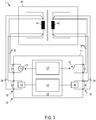
- Figure 1 shows a system 1 with a transformer testing device 10 according to an embodiment.
- the system 1 comprises a transformer 40 and the transformer testing device 10.
- the transformer testing device 10 can be designed as a single device with a housing 11.
- the transformer test apparatus 10 can consist of an arrangement of several devices or devices. In this case, the multiple devices or devices can be controlled by a central controller.
- the transformer testing device 10 can be designed as a mobile device and in particular as a portable device. If the transformer testing device 10 consists of several devices, each of the devices can be designed as a portable device.
- the transformer 40 can be a power transformer of an electrical energy supply device.
- the transformer 40 can be permanently installed in a power station or substation, while a transformer test is carried out with the transformer testing device 10.
- the transformer 40 can be a voltage converter or a current converter.
- the transformer 40 can be a voltage converter or a current converter which works according to the inductive operating principle.
- the transformer 40 comprises at least a first winding 41 and a second winding 42. It does not matter whether the first winding 41 is the primary winding and the second winding 42 is the secondary winding or vice versa. It is also irrelevant whether the first winding 41 is the high-voltage winding and the second winding 42 is the low-voltage winding, or vice versa.
- the transformer testing device 10 comprises several connections 12, a source 13 for a test signal that is applied to or impressed on the transformer 40 as a test object during the transformer test, and a controllable switching means 15.
- the controllable switching means 15 can, for example, be a relay, an IGBT or an FET be.
- the source 13 can be a current source which is controllable in order to generate a direct current and / or an alternating current as a test signal.
- the source 13 can be controllable in order to generate alternating currents with several different frequencies as a test signal.
- the source 13 can be a voltage source which can be controlled in order to generate a direct voltage and / or an alternating voltage as a test signal.
- the source 13 can be controllable in order to generate alternating voltages with several different frequencies as a test signal.
- the source 13 can be operated in different operating modes, for example as a current source or as a voltage source and / or as a source of a signal that is constant over time or an alternating signal.
- the source 13 can comprise a current measuring device.
- the source 13 can be set up to use an output signal of the current measuring device in a control loop for current control. Alternatively or additionally, a current measuring device can be connected in series with the source 13.
- the transformer test device 10 can comprise further devices, for example one or more measuring devices 14, 16 for detecting a test response in response to the test signal.
- the transformer testing device 10 can comprise a control device 17 for the automatic electrical control of the controllable switching means 15.
- the transformer test device 10 can comprise an evaluation device 18 for evaluating a test response of the transformer 40, which is recorded with the measuring devices 14, 16.
- the first measuring device 14 and the second measuring device 16 can each be set up for a voltage measurement, for example.
- the first measuring device 14 and the second measuring device 16 can each be set up to record other electrical parameters.
- the functions of the control device 17 and / or the evaluation device 18 can be carried out by a processor 19 or another integrated semiconductor circuit 19.
- the source 13 can generate a test signal that varies over time.
- a frequency of the test signal can be changed between several values.
- the first measuring device 14 and the second measuring device 16 can be used for time-resolved acquisition a test response must be set up.
- Measured values that are recorded by the first measuring device 14 and the second measuring device 16 can be A / D-converted and further computationally evaluated, for example in order to determine parameters of the transformer for each of several frequencies.
- the ports 12 include output ports 31 coupled to the source 13.
- the output connections 31 are electrically conductively connected to the first winding 41 of the transformer 40 via one or more lines 35.
- the terminals 12 include input terminals 32, 34 connected to one or more windings of the transformer via one or more lines 36, 38 to detect a test response of the transformer 10.
- a measuring device 14 can, for example, be connected to the first winding 41 via further lines 37 separate from the lines 35.
- the measuring device 14 can be a voltmeter.
- Such a connection between the transformer testing device 10 and the transformer 40 allows, for example, a measurement using what is known as a four-wire method.
- the separate routing of voltage lines from the input connection 32 to the first winding 41 can ensure that a voltage drop in the line 31 between the output connection 31 and the first winding 41 does not falsify the measurement result.
- the transformer testing device 10 comprises at least one pair of connections 33, which can be short-circuited via the controllable switching means 15.
- the controllable switching means can be a conventional switch, a mechanical-electrical switch, a relay, an FET, an IGBT or another component which is suitable for establishing an electrically conductive connection between the connections 33 depending on a state of the switching means.
- the conductive path in the transformer test apparatus 10 between the terminals 33 has an impedance which is less than an impedance of the winding 42 at at least one frequency or all frequencies with which the test signal is generated by the source 13 to which the pair of terminals 33 are connected via lines 37.
- the second winding 42 can also be connected to the connections 12 of the transformer testing device 10 via at least four lines 37, 38.
- the input terminals 34 can include a voltage input 34 which can be connected to a further voltmeter in order to connect it to the second winding 42 of the transformer 40 to be connected can be connected. Because the lines 37 and 38 are routed separately, falsification of the measurement results due to a possible voltage drop on the line 37 between the pair of connections 33 and the second winding 42 can be prevented.
- the transformer 40 can also include more than two windings 41, 42.
- the transformer testing device 10 can include connections for connection to a third winding of the transformer 40 and any further windings of the transformer 40.
- the transformer tester 10 may include terminals for connection to each winding of the transformer 40 for a four-wire measurement.
- the transformer testing device 10 can also comprise at least one second controllable switch 15 in order to short-circuit the first winding 41 or further windings of the transformer 40 when these are connected to the transformer testing device 10.
- the transformer test apparatus 10 can be configured to short-circuit combinations of two windings. For example, two of three windings of a transformer can be short-circuited simultaneously or sequentially. Test procedures can also be run automatically in which only one of several windings of the transformer is initially short-circuited and then two or more than two windings are short-circuited simultaneously or sequentially. The short-circuiting can in each case be carried out automatically by a controllable switching means of the transformer testing device 10.
- the transformer testing device 10 is set up in such a way that different measurements can be carried out without the connections 35-38 between the transformer testing device 10 and the transformer 40 having to be detached and / or otherwise connected.
- the various measurements can be carried out without the device under test having to be rewired.
- the measurements can be carried out by the transformer test device 10 in a fully or partially automated manner, i.e. without user interaction between the measurements.
- the controllable switching means 15 can short-circuit at least one of the windings of the transformer 40.
- the transformer testing device 10 can carry out a translation measurement.
- the source 13 can be operated as an alternating voltage source.
- the switch 15 can be open.
- a voltage on the first winding 41 can be detected with the first measuring device 14.
- a voltage on the second winding 42 can be detected with the second measuring device 16.
- the transformation ratio can be determined by the transformer testing device 10 from a ratio of the voltages.
- the transformer testing device 10 can alternatively or additionally be set up to carry out a short-circuit impedance measurement.
- the source 13 can be operated as an alternating current source.
- the switch 15 can be closed. This can be done by a control signal from the control device 17.
- the voltage on the first winding 41 can be detected with the first measuring device 14.
- a current in the second winding 42 can optionally be detected.
- the detected current in the second winding 42 can be used by the evaluation device 18 for correction purposes. For example, an error that arises due to a resistance of the lines 37, 38 from the second winding 42 to the test device 10 can be at least partially corrected.
- the transformer testing device 10 can alternatively or additionally be set up to carry out a winding resistance measurement.
- the resistance measurement can be a static resistance measurement.
- the winding resistance of the first winding 41 can be determined.
- the source 13 can operate as a direct current source.
- the voltage on the first winding 41 can be measured by the first measuring device 14.
- the direct current can be impressed until an iron core of the transformer 40 saturates.
- the controllable switching means 15 can be opened in order to reach the state in which the iron core is saturated more quickly.
- the controllable switching means 15 can be controlled in such a way that it is closed in order to short-circuit the second winding 42 when a winding resistance measurement, a short-circuit impedance measurement, a leakage impedance measurement or other measurements are carried out after the transformer core is saturated.
- a voltage at the second winding 42 can also be measured with the second measuring device 16 and used to correct errors, for example due to line resistances.
- the transformer testing device 10 can alternatively or additionally be set up to detect a behavior of the transformer 30 at the moment the transmission ratio is switched. Such a measurement is also referred to as a dynamic resistance measurement.
- the controllable switch 15 can in each case be closed at least when the changeover of the transmission ratio takes place. As a result, the effects detected at the first winding 14, which are caused by the switching process, can be intensified.
- the transformer testing device 10 can be carried out without the connections between the transformer testing device 10 and the transformer 40 having to be changed by user intervention for this purpose.
- the multiple measurements can be carried out without the connection points of the connections 35-38 on the transformer 40 and on the connections 12 of the transformer testing device 10 having to be changed.
- the control device 17 can be set up to control the controllable switching means 15 electrically.
- the control device 17 can switch the controllable switching means 15 to a closed state during part of a transformer test or during the entire transformer test in order to short-circuit the second winding 42.
- the transformer testing device 10 can be set up to carry out several different measurements sequentially, it being possible for the measurements and optionally also their sequence to be defined in a user-defined manner.
- the transformer testing device 10 can comprise a graphical user interface with which it is possible to define in a user-defined manner which measurements are carried out.
- the controllable switching means 15 and the source 13 can be controlled as a function of time in such a way that the selected measurements are carried out. It is also possible to select only a single measurement, for example a measurement of the transmission ratio or a winding resistance measurement or a leakage impedance measurement.
- the transformer testing device 10 then switches the controllable switching means 15 according to the selected measurement.
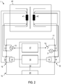
- FIG. 2 is an illustration of a system 1 with a transformer testing device 10 according to a further embodiment.
- the transformer testing device 10 comprises a graphical user interface 20.
- the graphical user interface 20 can be set up to allow a user-defined definition of measurements that are carried out with the transformer testing device 10.
- the controllable switching means 15 can be switched once or several times during the transformer test. The switching of the controllable switching means 15 can take place automatically under the control of the control device 17 without requiring a user input or other user action after the transformer test has been started.
- the transformer testing device 10 shown also has an ammeter 21 which is connected in series with the controllable switching means 15.
- the ammeter 21 may have an internal resistance that is much smaller than an impedance of the second winding 42 to which the terminals 33 are connected.
- An output signal of the ammeter 21 can be evaluated by the evaluation device 18, for example in order to correct the voltages detected by the measuring devices 14, 16.
- FIG 3 is an illustration of a system 1 with a transformer testing device 10 according to a further embodiment.
- the measuring devices 14, 16 are designed as voltmeters in order to detect a voltage drop across the first winding 41 and the second winding 42.
- Other configurations of the measuring devices 14, 16 can be used.
- FIG. 3 is a flow diagram of a method 50 according to an embodiment.
- the method 50 can be carried out automatically by the transformer testing device 10 according to one exemplary embodiment.
- a selection of a test procedure can take place.
- the testing procedure may include one or more measurements performed on the transformer 40.
- the test procedure can be selected in a user-defined manner from a plurality of test procedures.
- controllable switching means 15 is controlled as a function of the selected test procedure.
- the controllable switching means 15 can be automatically controlled so that one winding of the transformer 40 during the entire Test procedure or during part of the test procedure is short-circuited. A short-circuit current of the winding flows through the transformer testing device 10.
- the source for generating the test signal is controlled.
- the source can be controlled in such a way that it optionally generates a direct current, a direct voltage or an alternating voltage.
- Different test signals can also be generated as a function of time.
- the activation of the source and the activation of the controllable switch can be coordinated with one another in terms of time.
- the controllable switching means can be controlled in each case so that the second winding 42 is not short-circuited while the source impresses a direct current on the first winding 41.
- a test response of the transformer 40 can be evaluated automatically.
- the evaluation can include the determination of a winding resistance in a static resistance measurement, the determination of a leakage impedance, the determination of a leakage inductance, the determination of a transmission ratio or the determination of a combination of two or more than two of these parameters.
- controllable switching means 15 can be switched one or more times.
- FIG. 5 and Figure 6 illustrate by way of example a control signal Ctrl_s for controlling the controllable switching means 15 during a test procedure.
- the control signal can be generated automatically by a semiconductor integrated circuit of the transformer test apparatus 10.
- the control signal can be generated automatically by an integrated semiconductor circuit of the transformer testing device 10 in accordance with a time schedule or as a function of an output signal from at least one of the measuring devices 14, 16, 21 of the transformer testing device 10.
- Figure 5 illustrates a control signal 60 for activating the controllable switching means 15 during a test procedure which can be carried out by the transformer test device 10.
- the duration of the examination procedure has the control signal 60 has a first value and the controllable switching means 15 is open, so that the controllable switching means 15 does not short-circuit the winding 42.
- the controllable switching means 15 is switched to the closed state in order to short-circuit the second winding 42.
- the control signal 60 is changed to a second value.
- the controllable switching means is closed in order to short-circuit the second winding 42.
- the point in time at which the controllable switching means 15 is closed can be established, for example, by a time schedule or can depend on a condition. For example, saturation of the transformer core can be monitored.
- the controllable switching means 15 can be closed when the transformer core is completely saturated or when the saturation fulfills a predetermined criterion.
- Figure 6 illustrates a control signal 65 for controlling the controllable switching means 15 during a test procedure which can be carried out by the transformer test device 10.
- the controllable switching means 15 is switched several times into the closed and the open state while the test procedure is being carried out. For example, in a part 66 of the test procedure, the controllable switching means 15 can be open in each case, so that the second winding 42 is not short-circuited. In another part 67 of the test procedure, the controllable switching means 15 can be closed, so that the second winding 42 is short-circuited.
- the point in time at which the controllable switching means 15 is closed and opened in each case can be established, for example, by a time schedule or can depend on a condition, as with reference to FIG Figure 5 has been described.
- the transformer testing device 10 can comprise a plurality of controllable switching means.
- the control signals for the several controllable switching means can be generated in a time-coordinated manner in order to run a test procedure in which either one winding or several windings of the transformer are short-circuited without having to rewiring.
- FIG 7 is an illustration of a system 1 with a transformer test apparatus 10 according to an embodiment.
- the transformer 40 is set up so that a transformation ratio can be changed.
- the transformer 40 can comprise, for example, a tap changer 43 which has a first winding 41.
- the structure and mode of operation of the tap changer 43 are known to those skilled in the art.
- the transformer testing device 10 can be set up to monitor and evaluate a behavior of the transformer 40 during the switchover of the tap changer 43.
- the transformer testing device 10 can in particular be set up for a dynamic resistance measurement.
- a winding resistance of the tap changer 43 between the two connections of the tap changer when switching can be determined.
- a direct current or alternating current can be impressed by the source 13 and a voltage drop across the tap changer 41 can be detected with the measuring device 14.
- the controllable switching means 15 is set up to selectively short-circuit the second winding 42 on the side of the transformer 40 on which no tap changer is provided.
- the controllable switching means 15 can be closed when the step switch 41 is switched over in order to short-circuit the second winding 42. In this way, particularly clear effects can be observed during the switchover process.
- the controllable switching means 15 can be opened between two processes, so that the second winding 42 is not short-circuited. As a result, the behavior of the transformer 40 can be stabilized more quickly.
- a static resistance measurement can also be carried out for each switching stage of the tap changer 41, in which the resistance of the tap changer 41 is determined for one or more frequencies.
- the transformer testing device 10 can comprise an interface in order to carry out the switching of the controllable switching means 15 in a coordinated manner with switching operations of the tap changer 41.
- the transformer testing device 10 can be set up to trigger switching operations of the tap changer 41.
- the transformer testing device 10 can start a switching process by monitoring the voltage at the tap changer are automatically recognized and can serve as a trigger for an automatic switching of the controllable switching means 15 into the closed state.
- FIG. 7 is a flow diagram of a method 70 according to an embodiment.
- the method 70 can be carried out automatically by the transformer testing device 10 for testing a transformer comprising a tap changer.
- the transformer testing apparatus 10 is detachably connected to the transformer 40.
- the tap changer can be brought into an initial position which, for example, can correspond to a maximum self-inductance of the tap changer.
- the behavior of the transformer 40 can then be automatically recorded each time the tap changer 43 is switched over.
- a static resistance measurement can be carried out for each switching stage of the tap changer 43 in order to determine the winding resistance of the tap changer 43.
- other measurements can be made between the switching operations of the tap changer 43.
- step 73 the controllable switching means 15 can be in a state in which the second winding 42 is not short-circuited. This enables the transformer to stabilize more quickly if a direct current is impressed on the primary side.
- a resistance measurement can be made.
- a winding resistance of the tap changer 43 can be determined.
- step 75 the controllable switching means 15 can be activated in such a way that it is closed in order to short-circuit the second winding 42.
- step 76 the step switch 43 can be actuated so that a switchover process between different switching steps is triggered.
- the voltage at the step switch 43 can be measured.
- the source 13 can, for example, impress a direct current. From the captured Voltage, a dynamic resistance can be determined during the switching process.
- step 77 it can be checked whether the last step of the step switch 43 has been reached.
- the last stage can, for example, be the stage in which the tap changer 43 has the lowest self-inductance. If the last shift stage has not yet been reached, the method can return to step 73.
- the controllable switching means 15 can be opened in order not to short-circuit the second winding 42.
- the transformer test device can be disconnected from the transformer in step 78.
- An automatic further evaluation and / or archiving of the results of the transformer test can be carried out by the transformer test device.
- the transformer testing device can comprise only one controllable switching means for short-circuiting only one winding of the transformer, the transformer testing device can also have two or more than two controllable switching means for short-circuiting several turns of the transformer.
- the transformer testing device can be set up to short-circuit a plurality of windings simultaneously or in a time-sequential manner.
- the transformer test device can be set up to short-circuit a low-voltage side of a transformer
- the transformer test device can also be set up to short-circuit the high-voltage side or a tertiary winding of the transformer with the controllable switching means as an alternative or in addition to the low-voltage side.
- the transformer test device and the method according to exemplary embodiments can also be used if only one characteristic of the transformer is measured before a new user input is required.
- the transformer can be installed in a power station or substation of an energy supply network
- the transformer testing device and the method according to the exemplary embodiments can also be used with smaller transformers.
- Transformer testing device methods and systems according to exemplary embodiments allow further automation in transformer testing.
Landscapes
- Physics & Mathematics (AREA)
- General Physics & Mathematics (AREA)
- Engineering & Computer Science (AREA)
- Power Engineering (AREA)
- Testing Of Short-Circuits, Discontinuities, Leakage, Or Incorrect Line Connections (AREA)
- Testing Relating To Insulation (AREA)
- Testing Electric Properties And Detecting Electric Faults (AREA)
Priority Applications (1)
| Application Number | Priority Date | Filing Date | Title |
|---|---|---|---|
| PL15786959T PL3213095T3 (pl) | 2014-10-30 | 2015-10-28 | Urządzenie do testowania transformatora i sposób testowania transformatora |
Applications Claiming Priority (2)
| Application Number | Priority Date | Filing Date | Title |
|---|---|---|---|
| AT507832014 | 2014-10-30 | ||
| PCT/EP2015/075018 WO2016066701A1 (de) | 2014-10-30 | 2015-10-28 | Transformatorprüfvorrichtung und verfahren zum prüfen eines transformators |
Publications (2)
| Publication Number | Publication Date |
|---|---|
| EP3213095A1 EP3213095A1 (de) | 2017-09-06 |
| EP3213095B1 true EP3213095B1 (de) | 2021-05-19 |
Family
ID=54360466
Family Applications (1)
| Application Number | Title | Priority Date | Filing Date |
|---|---|---|---|
| EP15786959.5A Active EP3213095B1 (de) | 2014-10-30 | 2015-10-28 | Transformatorprüfvorrichtung und verfahren zum prüfen eines transformators |
Country Status (13)
| Country | Link |
|---|---|
| US (1) | US10955490B2 (pl) |
| EP (1) | EP3213095B1 (pl) |
| KR (1) | KR101943471B1 (pl) |
| CN (1) | CN107110903A (pl) |
| AU (1) | AU2015340618B2 (pl) |
| BR (1) | BR112017008629B8 (pl) |
| CA (1) | CA2966456C (pl) |
| ES (1) | ES2881865T3 (pl) |
| MX (1) | MX367672B (pl) |
| PL (1) | PL3213095T3 (pl) |
| RU (1) | RU2664924C1 (pl) |
| WO (1) | WO2016066701A1 (pl) |
| ZA (1) | ZA201702992B (pl) |
Families Citing this family (19)
| Publication number | Priority date | Publication date | Assignee | Title |
|---|---|---|---|---|
| ES3033848T3 (en) * | 2015-02-06 | 2025-08-08 | Omicron Electronics Gmbh | Device and method for determining a parameter of a transformer |
| US11105838B2 (en) * | 2018-01-19 | 2021-08-31 | Avo Multi-Amp Corporation | System and method for measuring turns ratio of a transformer |
| AT521563B1 (de) * | 2018-07-26 | 2025-05-15 | Omicron Electronics Gmbh | Prüfvorrichtung, Verfahren und System zum Prüfen eines Mehrphasen-Stufenschalters eines Mehrphasen-Transformators |
| WO2020025380A1 (de) * | 2018-07-31 | 2020-02-06 | Siemens Aktiengesellschaft | Flammenionisationsdetektor und verfahren zur analyse eines sauerstoffhaltigen messgases |
| CN109239495A (zh) * | 2018-09-26 | 2019-01-18 | 合肥博微田村电气有限公司 | 一种变压器性能自动检测装置 |
| US10958062B2 (en) * | 2018-11-13 | 2021-03-23 | Rockwell Automation Technologies, Inc. | Systems and methods for dynamically switching a load of a current transformer circuit |
| CN110286290A (zh) * | 2019-07-09 | 2019-09-27 | 江苏安方电力科技有限公司 | 一种变压器自动接线装置 |
| KR102235052B1 (ko) * | 2019-09-26 | 2021-04-01 | 한국전력공사 | Oltc 동작 분석 장치 및 그 방법 |
| AT523776B1 (de) | 2020-05-13 | 2022-08-15 | Omicron Electronics Gmbh | Prüfsystem sowie Hauptgerät und Zusatzgerät davon zur Prüfung einer elektrischen Einrichtung |
| RU201525U1 (ru) * | 2020-08-28 | 2020-12-21 | Федеральное государственное унитарное предприятие «Всероссийский научно-исследовательский институт метрологии им. Д.И.Менделеева» (ФГУП «ВНИИМ им.Д.И.Менделеева») | Устройство поверки измерительных трансформаторов тока |
| CN112433105B (zh) * | 2020-10-27 | 2024-02-09 | 吴江变压器有限公司 | 变压器半成品变比测量方法 |
| CN112748371B (zh) * | 2020-12-18 | 2024-03-12 | 国网福建省电力有限公司检修分公司 | 变压器试验多测试项目的通用测试结构及逻辑控制方法 |
| CN112816906B (zh) * | 2020-12-28 | 2023-04-14 | 国电南瑞科技股份有限公司 | 配网直流变压器中压侧双极短路试验平台与方法 |
| CN113064104A (zh) * | 2021-03-17 | 2021-07-02 | 安徽莱特实业集团有限公司 | 一种全自动变比及直流电阻测试装置 |
| FR3124268B1 (fr) * | 2021-06-16 | 2023-06-30 | Sagemcom Energy & Telecom Sas | Détection de l’ouverture d’un transformateur externe |
| TWI807440B (zh) * | 2021-10-04 | 2023-07-01 | 柯伯呈 | 電力變壓器良劣判斷之互動測驗裝置 |
| KR102654141B1 (ko) * | 2021-11-23 | 2024-04-04 | 한국전력공사 | 변압기 특성 시험 장치 및 방법 |
| CN114325475B (zh) * | 2021-12-29 | 2024-04-09 | 苏州电器科学研究院股份有限公司 | 特高压变压器短路试验系统的供电电路及方法 |
| US20240219481A1 (en) * | 2022-12-30 | 2024-07-04 | Schneider Electric USA, Inc. | Apparatuses, systems, and methods for screening electronic components |
Citations (2)
| Publication number | Priority date | Publication date | Assignee | Title |
|---|---|---|---|---|
| US20040124860A1 (en) * | 2001-12-20 | 2004-07-01 | Hamdan Fadi Adel | Automated test sequence editor and engine for transformer testing |
| US20140210495A1 (en) * | 2013-01-21 | 2014-07-31 | Tatsumi Corporation | Load testing machine |
Family Cites Families (15)
| Publication number | Priority date | Publication date | Assignee | Title |
|---|---|---|---|---|
| SU445001A1 (ru) | 1972-06-23 | 1974-09-30 | Научно-Исследовательский Центр По Испытанию Высоковольтной Аппаратуры | Устройство дл испытани трансформаторов |
| US4177419A (en) * | 1976-03-15 | 1979-12-04 | Bbc Brown Boveri & Company Ltd. | Test apparatus for checking the response of protective relays |
| US4241306A (en) * | 1978-08-29 | 1980-12-23 | Bump Russell E | Test fixture having switching means for facilitating transformer turns ratio testing |
| SU1335904A1 (ru) | 1986-01-06 | 1987-09-07 | Всесоюзный Элетротехнический Институт Им.В.И.Ленина | Устройство дл испытаний трансформаторов на электродинамическую стойкость при коротком замыкании |
| JP3987950B2 (ja) * | 2001-12-27 | 2007-10-10 | サンケン電気株式会社 | Dc−dcコンバータ |
| US6809525B1 (en) * | 2002-12-31 | 2004-10-26 | Abb Technology Ag | Method and system for estimating conductor losses in a transformer |
| US20050035767A1 (en) * | 2003-08-11 | 2005-02-17 | Hardy William Dean | Plug detector for an electrical test instrument |
| GB2411733B (en) | 2004-03-04 | 2007-09-12 | Robinson Instr Ltd | Method and apparatus for characterising a three phase transformer using a single phase power supply |
| CN101527516B (zh) | 2008-03-05 | 2013-04-24 | 深圳诺尔科技股份有限公司 | 变压调压电路 |
| US9134348B2 (en) * | 2009-04-16 | 2015-09-15 | Panoramic Power Ltd. | Distributed electricity metering system |
| RU2447536C2 (ru) | 2010-07-06 | 2012-04-10 | Федеральное государственное унитарное предприятие "Всероссийский электротехнический институт имени В.И. Ленина" | Устройство управляемой коммутации |
| KR101399922B1 (ko) | 2012-07-12 | 2014-05-29 | (주)시티이텍 | 변류기 보호장치 |
| RU2506600C1 (ru) | 2012-08-28 | 2014-02-10 | Федеральное государственное унитарное предприятие "Всероссийский электротехнический институт им. В.И. Ленина" | Способ испытания силовых трансформаторов от сети на стойкость к токам короткого замыкания |
| CN103698621B (zh) | 2013-09-05 | 2016-08-17 | 国家电网公司 | 一种变压器车载式综合测试系统 |
| US10374597B2 (en) * | 2014-04-15 | 2019-08-06 | Bae Systems Plc | Circuit state sensing |
-
2015
- 2015-10-28 RU RU2017114164A patent/RU2664924C1/ru active
- 2015-10-28 EP EP15786959.5A patent/EP3213095B1/de active Active
- 2015-10-28 CA CA2966456A patent/CA2966456C/en active Active
- 2015-10-28 WO PCT/EP2015/075018 patent/WO2016066701A1/de not_active Ceased
- 2015-10-28 BR BR112017008629A patent/BR112017008629B8/pt active IP Right Grant
- 2015-10-28 KR KR1020177014367A patent/KR101943471B1/ko active Active
- 2015-10-28 ES ES15786959T patent/ES2881865T3/es active Active
- 2015-10-28 CN CN201580059552.2A patent/CN107110903A/zh active Pending
- 2015-10-28 PL PL15786959T patent/PL3213095T3/pl unknown
- 2015-10-28 AU AU2015340618A patent/AU2015340618B2/en active Active
- 2015-10-28 MX MX2017005624A patent/MX367672B/es active IP Right Grant
- 2015-10-28 US US15/522,323 patent/US10955490B2/en active Active
-
2017
- 2017-04-28 ZA ZA2017/02992A patent/ZA201702992B/en unknown
Patent Citations (3)
| Publication number | Priority date | Publication date | Assignee | Title |
|---|---|---|---|---|
| US20040124860A1 (en) * | 2001-12-20 | 2004-07-01 | Hamdan Fadi Adel | Automated test sequence editor and engine for transformer testing |
| EP1456678A1 (en) * | 2001-12-20 | 2004-09-15 | ABB Inc. | Automated test sequence editor and engine for transformer testing |
| US20140210495A1 (en) * | 2013-01-21 | 2014-07-31 | Tatsumi Corporation | Load testing machine |
Non-Patent Citations (1)
| Title |
|---|
| "Diagnostic Testing Solutions for Power Transformers", 30 May 2013 (2013-05-30), pages 1 - 32, XP055196347, Retrieved from the Internet <URL:https://www.omicron.at/fileadmin/user_upload/pdf/literature/Transformer-brochure-ENU.pdf> [retrieved on 20150617] * |
Also Published As
| Publication number | Publication date |
|---|---|
| CN107110903A (zh) | 2017-08-29 |
| MX367672B (es) | 2019-08-30 |
| ES2881865T3 (es) | 2021-11-30 |
| KR101943471B1 (ko) | 2019-01-29 |
| CA2966456A1 (en) | 2016-05-06 |
| BR112017008629B1 (pt) | 2023-01-17 |
| EP3213095A1 (de) | 2017-09-06 |
| WO2016066701A1 (de) | 2016-05-06 |
| BR112017008629B8 (pt) | 2023-03-14 |
| AU2015340618A1 (en) | 2017-05-18 |
| BR112017008629A2 (pt) | 2017-12-26 |
| ZA201702992B (en) | 2019-03-27 |
| US10955490B2 (en) | 2021-03-23 |
| KR20170102456A (ko) | 2017-09-11 |
| AU2015340618B2 (en) | 2018-05-24 |
| CA2966456C (en) | 2019-04-23 |
| MX2017005624A (es) | 2017-08-07 |
| US20170336462A1 (en) | 2017-11-23 |
| RU2664924C1 (ru) | 2018-08-23 |
| PL3213095T3 (pl) | 2021-12-06 |
Similar Documents
| Publication | Publication Date | Title |
|---|---|---|
| EP3213095B1 (de) | Transformatorprüfvorrichtung und verfahren zum prüfen eines transformators | |
| EP3245527B1 (de) | Transformatorprüfvorrichtung und verfahren zum prüfen eines transformators | |
| EP3254124B1 (de) | Vorrichtung und verfahren zum ermitteln einer kenngrösse eines transformators | |
| DE102011076320A1 (de) | Erdungsüberwachungs-Vorrichtung | |
| EP3391063B1 (de) | Mobile transformatorprüfvorrichtung und verfahren zum prüfen eines leistungstransformators | |
| WO2014005674A1 (de) | Diagnoseeinrichtung zur überprüfung einer steuersignalleitung | |
| EP3631976A1 (de) | Verfahren zur erkennung eines kontaktfehlers in einer photovoltaikanlage | |
| DE102011108716A1 (de) | Lokalisierung und identifikation eines isolierungsfehlers für ein elektrisches leistungssystem mit isoliertem nullleiter | |
| EP3254127B1 (de) | Transformatorprüfvorrichtung und verfahren zum prüfen eines dreiwicklungstransformators | |
| EP3308179B1 (de) | Schaltvorrichtung, testvorrichtung und verfahren zum betreiben einer schaltvorrichtung für ein messgerät für einen transformator | |
| EP2882605A2 (de) | Diagnoseeinrichtung zur überprüfung einer steuersignalleitung | |
| DE102012011275A1 (de) | Zählerprüfeinrichtung und Zählerprüfverfahren zum Prüfen eines Elektrizitätszählers | |
| AT521563B1 (de) | Prüfvorrichtung, Verfahren und System zum Prüfen eines Mehrphasen-Stufenschalters eines Mehrphasen-Transformators | |
| DE10207856A1 (de) | Verfahren und Vorrichtung zur Messung der Impedanz eines elektrischen Energieversorgungsnetzes | |
| EP3532857A1 (de) | Vorrichtung und verfahren zur diagnose der erfassung eines mehrphasigen elektrischen stroms | |
| DE10141349A1 (de) | Nicht-intrusives Fehlerlokalisierungssystem für ein Überhitzungs-Detektionssystem | |
| CH619545A5 (pl) | ||
| EP3794361B1 (de) | Zustandsanalyse eines induktiven betriebsmittels | |
| EP3311179B1 (de) | Prüfvorrichtung und verfahren zum betreiben einer prüfvorrichtung | |
| DE102019126438A1 (de) | Kompensationsvorrichtung für Ableitströme | |
| WO2011124338A1 (de) | Vorrichtung und verfahren zur diagnose von messobjekten unter verwendung einer messspannung | |
| WO2023088877A1 (de) | Prüfsystem und verfahren zum bestimmen einer kapazität einer hochspannungseinrichtung | |
| EP3832319A1 (de) | Verfahren und vorrichtung zum überprüfen einer funktionsfähigkeit eines als systemwiderstand dienenden widerstands eines batteriesystems | |
| DE2319325A1 (de) | Verfahren und einrichtung zum pruefen elektrischer rohrheizkoerper |
Legal Events
| Date | Code | Title | Description |
|---|---|---|---|
| STAA | Information on the status of an ep patent application or granted ep patent |
Free format text: STATUS: THE INTERNATIONAL PUBLICATION HAS BEEN MADE |
|
| PUAI | Public reference made under article 153(3) epc to a published international application that has entered the european phase |
Free format text: ORIGINAL CODE: 0009012 |
|
| STAA | Information on the status of an ep patent application or granted ep patent |
Free format text: STATUS: REQUEST FOR EXAMINATION WAS MADE |
|
| 17P | Request for examination filed |
Effective date: 20170530 |
|
| AK | Designated contracting states |
Kind code of ref document: A1 Designated state(s): AL AT BE BG CH CY CZ DE DK EE ES FI FR GB GR HR HU IE IS IT LI LT LU LV MC MK MT NL NO PL PT RO RS SE SI SK SM TR |
|
| AX | Request for extension of the european patent |
Extension state: BA ME |
|
| DAV | Request for validation of the european patent (deleted) | ||
| DAX | Request for extension of the european patent (deleted) | ||
| STAA | Information on the status of an ep patent application or granted ep patent |
Free format text: STATUS: EXAMINATION IS IN PROGRESS |
|
| 17Q | First examination report despatched |
Effective date: 20200514 |
|
| REG | Reference to a national code |
Ref country code: DE Ref legal event code: R079 Ref document number: 502015014734 Country of ref document: DE Free format text: PREVIOUS MAIN CLASS: G01R0031020000 Ipc: G01R0031520000 |
|
| GRAP | Despatch of communication of intention to grant a patent |
Free format text: ORIGINAL CODE: EPIDOSNIGR1 |
|
| STAA | Information on the status of an ep patent application or granted ep patent |
Free format text: STATUS: GRANT OF PATENT IS INTENDED |
|
| RIC1 | Information provided on ipc code assigned before grant |
Ipc: G01R 31/52 20200101AFI20210126BHEP Ipc: H01H 9/00 20060101ALI20210126BHEP Ipc: G01R 31/62 20200101ALI20210126BHEP |
|
| INTG | Intention to grant announced |
Effective date: 20210211 |
|
| GRAS | Grant fee paid |
Free format text: ORIGINAL CODE: EPIDOSNIGR3 |
|
| GRAA | (expected) grant |
Free format text: ORIGINAL CODE: 0009210 |
|
| STAA | Information on the status of an ep patent application or granted ep patent |
Free format text: STATUS: THE PATENT HAS BEEN GRANTED |
|
| AK | Designated contracting states |
Kind code of ref document: B1 Designated state(s): AL AT BE BG CH CY CZ DE DK EE ES FI FR GB GR HR HU IE IS IT LI LT LU LV MC MK MT NL NO PL PT RO RS SE SI SK SM TR |
|
| REG | Reference to a national code |
Ref country code: GB Ref legal event code: FG4D Free format text: NOT ENGLISH |
|
| REG | Reference to a national code |
Ref country code: CH Ref legal event code: EP |
|
| REG | Reference to a national code |
Ref country code: DE Ref legal event code: R096 Ref document number: 502015014734 Country of ref document: DE |
|
| REG | Reference to a national code |
Ref country code: AT Ref legal event code: REF Ref document number: 1394509 Country of ref document: AT Kind code of ref document: T Effective date: 20210615 |
|
| REG | Reference to a national code |
Ref country code: IE Ref legal event code: FG4D Free format text: LANGUAGE OF EP DOCUMENT: GERMAN |
|
| REG | Reference to a national code |
Ref country code: NL Ref legal event code: FP |
|
| REG | Reference to a national code |
Ref country code: LT Ref legal event code: MG9D |
|
| REG | Reference to a national code |
Ref country code: SE Ref legal event code: TRGR |
|
| PG25 | Lapsed in a contracting state [announced via postgrant information from national office to epo] |
Ref country code: BG Free format text: LAPSE BECAUSE OF FAILURE TO SUBMIT A TRANSLATION OF THE DESCRIPTION OR TO PAY THE FEE WITHIN THE PRESCRIBED TIME-LIMIT Effective date: 20210819 Ref country code: HR Free format text: LAPSE BECAUSE OF FAILURE TO SUBMIT A TRANSLATION OF THE DESCRIPTION OR TO PAY THE FEE WITHIN THE PRESCRIBED TIME-LIMIT Effective date: 20210519 Ref country code: LT Free format text: LAPSE BECAUSE OF FAILURE TO SUBMIT A TRANSLATION OF THE DESCRIPTION OR TO PAY THE FEE WITHIN THE PRESCRIBED TIME-LIMIT Effective date: 20210519 Ref country code: FI Free format text: LAPSE BECAUSE OF FAILURE TO SUBMIT A TRANSLATION OF THE DESCRIPTION OR TO PAY THE FEE WITHIN THE PRESCRIBED TIME-LIMIT Effective date: 20210519 |
|
| PG25 | Lapsed in a contracting state [announced via postgrant information from national office to epo] |
Ref country code: GR Free format text: LAPSE BECAUSE OF FAILURE TO SUBMIT A TRANSLATION OF THE DESCRIPTION OR TO PAY THE FEE WITHIN THE PRESCRIBED TIME-LIMIT Effective date: 20210820 Ref country code: IS Free format text: LAPSE BECAUSE OF FAILURE TO SUBMIT A TRANSLATION OF THE DESCRIPTION OR TO PAY THE FEE WITHIN THE PRESCRIBED TIME-LIMIT Effective date: 20210919 Ref country code: LV Free format text: LAPSE BECAUSE OF FAILURE TO SUBMIT A TRANSLATION OF THE DESCRIPTION OR TO PAY THE FEE WITHIN THE PRESCRIBED TIME-LIMIT Effective date: 20210519 Ref country code: RS Free format text: LAPSE BECAUSE OF FAILURE TO SUBMIT A TRANSLATION OF THE DESCRIPTION OR TO PAY THE FEE WITHIN THE PRESCRIBED TIME-LIMIT Effective date: 20210519 Ref country code: PT Free format text: LAPSE BECAUSE OF FAILURE TO SUBMIT A TRANSLATION OF THE DESCRIPTION OR TO PAY THE FEE WITHIN THE PRESCRIBED TIME-LIMIT Effective date: 20210920 Ref country code: NO Free format text: LAPSE BECAUSE OF FAILURE TO SUBMIT A TRANSLATION OF THE DESCRIPTION OR TO PAY THE FEE WITHIN THE PRESCRIBED TIME-LIMIT Effective date: 20210819 |
|
| REG | Reference to a national code |
Ref country code: ES Ref legal event code: FG2A Ref document number: 2881865 Country of ref document: ES Kind code of ref document: T3 Effective date: 20211130 |
|
| PG25 | Lapsed in a contracting state [announced via postgrant information from national office to epo] |
Ref country code: SK Free format text: LAPSE BECAUSE OF FAILURE TO SUBMIT A TRANSLATION OF THE DESCRIPTION OR TO PAY THE FEE WITHIN THE PRESCRIBED TIME-LIMIT Effective date: 20210519 Ref country code: SM Free format text: LAPSE BECAUSE OF FAILURE TO SUBMIT A TRANSLATION OF THE DESCRIPTION OR TO PAY THE FEE WITHIN THE PRESCRIBED TIME-LIMIT Effective date: 20210519 Ref country code: EE Free format text: LAPSE BECAUSE OF FAILURE TO SUBMIT A TRANSLATION OF THE DESCRIPTION OR TO PAY THE FEE WITHIN THE PRESCRIBED TIME-LIMIT Effective date: 20210519 Ref country code: CZ Free format text: LAPSE BECAUSE OF FAILURE TO SUBMIT A TRANSLATION OF THE DESCRIPTION OR TO PAY THE FEE WITHIN THE PRESCRIBED TIME-LIMIT Effective date: 20210519 Ref country code: DK Free format text: LAPSE BECAUSE OF FAILURE TO SUBMIT A TRANSLATION OF THE DESCRIPTION OR TO PAY THE FEE WITHIN THE PRESCRIBED TIME-LIMIT Effective date: 20210519 Ref country code: RO Free format text: LAPSE BECAUSE OF FAILURE TO SUBMIT A TRANSLATION OF THE DESCRIPTION OR TO PAY THE FEE WITHIN THE PRESCRIBED TIME-LIMIT Effective date: 20210519 |
|
| REG | Reference to a national code |
Ref country code: DE Ref legal event code: R097 Ref document number: 502015014734 Country of ref document: DE |
|
| PLBE | No opposition filed within time limit |
Free format text: ORIGINAL CODE: 0009261 |
|
| STAA | Information on the status of an ep patent application or granted ep patent |
Free format text: STATUS: NO OPPOSITION FILED WITHIN TIME LIMIT |
|
| 26N | No opposition filed |
Effective date: 20220222 |
|
| PG25 | Lapsed in a contracting state [announced via postgrant information from national office to epo] |
Ref country code: IS Free format text: LAPSE BECAUSE OF FAILURE TO SUBMIT A TRANSLATION OF THE DESCRIPTION OR TO PAY THE FEE WITHIN THE PRESCRIBED TIME-LIMIT Effective date: 20210919 Ref country code: AL Free format text: LAPSE BECAUSE OF FAILURE TO SUBMIT A TRANSLATION OF THE DESCRIPTION OR TO PAY THE FEE WITHIN THE PRESCRIBED TIME-LIMIT Effective date: 20210519 |
|
| REG | Reference to a national code |
Ref country code: BE Ref legal event code: MM Effective date: 20211031 |
|
| PG25 | Lapsed in a contracting state [announced via postgrant information from national office to epo] |
Ref country code: MC Free format text: LAPSE BECAUSE OF FAILURE TO SUBMIT A TRANSLATION OF THE DESCRIPTION OR TO PAY THE FEE WITHIN THE PRESCRIBED TIME-LIMIT Effective date: 20210519 |
|
| PG25 | Lapsed in a contracting state [announced via postgrant information from national office to epo] |
Ref country code: LU Free format text: LAPSE BECAUSE OF NON-PAYMENT OF DUE FEES Effective date: 20211028 Ref country code: BE Free format text: LAPSE BECAUSE OF NON-PAYMENT OF DUE FEES Effective date: 20211031 |
|
| PG25 | Lapsed in a contracting state [announced via postgrant information from national office to epo] |
Ref country code: IE Free format text: LAPSE BECAUSE OF NON-PAYMENT OF DUE FEES Effective date: 20211028 |
|
| PG25 | Lapsed in a contracting state [announced via postgrant information from national office to epo] |
Ref country code: HU Free format text: LAPSE BECAUSE OF FAILURE TO SUBMIT A TRANSLATION OF THE DESCRIPTION OR TO PAY THE FEE WITHIN THE PRESCRIBED TIME-LIMIT; INVALID AB INITIO Effective date: 20151028 |
|
| P01 | Opt-out of the competence of the unified patent court (upc) registered |
Effective date: 20230324 |
|
| PG25 | Lapsed in a contracting state [announced via postgrant information from national office to epo] |
Ref country code: CY Free format text: LAPSE BECAUSE OF FAILURE TO SUBMIT A TRANSLATION OF THE DESCRIPTION OR TO PAY THE FEE WITHIN THE PRESCRIBED TIME-LIMIT Effective date: 20210519 |
|
| PG25 | Lapsed in a contracting state [announced via postgrant information from national office to epo] |
Ref country code: MK Free format text: LAPSE BECAUSE OF FAILURE TO SUBMIT A TRANSLATION OF THE DESCRIPTION OR TO PAY THE FEE WITHIN THE PRESCRIBED TIME-LIMIT Effective date: 20210519 |
|
| PG25 | Lapsed in a contracting state [announced via postgrant information from national office to epo] |
Ref country code: MT Free format text: LAPSE BECAUSE OF FAILURE TO SUBMIT A TRANSLATION OF THE DESCRIPTION OR TO PAY THE FEE WITHIN THE PRESCRIBED TIME-LIMIT Effective date: 20210519 |
|
| PGFP | Annual fee paid to national office [announced via postgrant information from national office to epo] |
Ref country code: DE Payment date: 20241016 Year of fee payment: 10 |
|
| PGFP | Annual fee paid to national office [announced via postgrant information from national office to epo] |
Ref country code: PL Payment date: 20241003 Year of fee payment: 10 |
|
| PGFP | Annual fee paid to national office [announced via postgrant information from national office to epo] |
Ref country code: GB Payment date: 20241025 Year of fee payment: 10 |
|
| PGFP | Annual fee paid to national office [announced via postgrant information from national office to epo] |
Ref country code: FR Payment date: 20241025 Year of fee payment: 10 Ref country code: AT Payment date: 20241021 Year of fee payment: 10 |
|
| PGFP | Annual fee paid to national office [announced via postgrant information from national office to epo] |
Ref country code: IT Payment date: 20241004 Year of fee payment: 10 Ref country code: ES Payment date: 20241106 Year of fee payment: 10 |
|
| PGFP | Annual fee paid to national office [announced via postgrant information from national office to epo] |
Ref country code: SE Payment date: 20241025 Year of fee payment: 10 |
|
| PGFP | Annual fee paid to national office [announced via postgrant information from national office to epo] |
Ref country code: CH Payment date: 20241101 Year of fee payment: 10 |
|
| PGFP | Annual fee paid to national office [announced via postgrant information from national office to epo] |
Ref country code: TR Payment date: 20241003 Year of fee payment: 10 |
|
| PGFP | Annual fee paid to national office [announced via postgrant information from national office to epo] |
Ref country code: NL Payment date: 20251023 Year of fee payment: 11 |
|
| REG | Reference to a national code |
Ref country code: CH Ref legal event code: U11 Free format text: ST27 STATUS EVENT CODE: U-0-0-U10-U11 (AS PROVIDED BY THE NATIONAL OFFICE) Effective date: 20251117 |