EP3213095B1 - Transformer test device and method for testing a transformer - Google Patents
Transformer test device and method for testing a transformer Download PDFInfo
- Publication number
- EP3213095B1 EP3213095B1 EP15786959.5A EP15786959A EP3213095B1 EP 3213095 B1 EP3213095 B1 EP 3213095B1 EP 15786959 A EP15786959 A EP 15786959A EP 3213095 B1 EP3213095 B1 EP 3213095B1
- Authority
- EP
- European Patent Office
- Prior art keywords
- transformer
- winding
- switching means
- test
- controllable switching
- Prior art date
- Legal status (The legal status is an assumption and is not a legal conclusion. Google has not performed a legal analysis and makes no representation as to the accuracy of the status listed.)
- Active
Links
- 238000012360 testing method Methods 0.000 title claims description 267
- 238000000034 method Methods 0.000 title claims description 57
- 238000004804 winding Methods 0.000 claims description 142
- 238000005259 measurement Methods 0.000 claims description 68
- 238000010998 test method Methods 0.000 claims description 31
- 230000004044 response Effects 0.000 description 14
- 230000008569 process Effects 0.000 description 10
- 238000002847 impedance measurement Methods 0.000 description 8
- 230000005540 biological transmission Effects 0.000 description 7
- 230000003068 static effect Effects 0.000 description 7
- 238000011156 evaluation Methods 0.000 description 6
- 230000036962 time dependent Effects 0.000 description 6
- 230000009466 transformation Effects 0.000 description 5
- XEEYBQQBJWHFJM-UHFFFAOYSA-N Iron Chemical group [Fe] XEEYBQQBJWHFJM-UHFFFAOYSA-N 0.000 description 4
- 230000008859 change Effects 0.000 description 4
- 238000010586 diagram Methods 0.000 description 4
- 239000004065 semiconductor Substances 0.000 description 4
- 230000008878 coupling Effects 0.000 description 3
- 238000010168 coupling process Methods 0.000 description 3
- 238000005859 coupling reaction Methods 0.000 description 3
- 230000005669 field effect Effects 0.000 description 3
- 229920006395 saturated elastomer Polymers 0.000 description 3
- 230000004913 activation Effects 0.000 description 2
- 230000000694 effects Effects 0.000 description 2
- 230000009471 action Effects 0.000 description 1
- 230000003213 activating effect Effects 0.000 description 1
- 238000006243 chemical reaction Methods 0.000 description 1
- 238000012937 correction Methods 0.000 description 1
- 238000002405 diagnostic procedure Methods 0.000 description 1
- 230000001939 inductive effect Effects 0.000 description 1
- 230000003993 interaction Effects 0.000 description 1
- 238000000691 measurement method Methods 0.000 description 1
- 238000012544 monitoring process Methods 0.000 description 1
- 238000012545 processing Methods 0.000 description 1
- 238000012956 testing procedure Methods 0.000 description 1
- 238000013519 translation Methods 0.000 description 1
- 230000001960 triggered effect Effects 0.000 description 1
Images


Classifications
-
- H—ELECTRICITY
- H01—ELECTRIC ELEMENTS
- H01H—ELECTRIC SWITCHES; RELAYS; SELECTORS; EMERGENCY PROTECTIVE DEVICES
- H01H9/00—Details of switching devices, not covered by groups H01H1/00 - H01H7/00
- H01H9/54—Circuit arrangements not adapted to a particular application of the switching device and for which no provision exists elsewhere
-
- G—PHYSICS
- G01—MEASURING; TESTING
- G01R—MEASURING ELECTRIC VARIABLES; MEASURING MAGNETIC VARIABLES
- G01R31/00—Arrangements for testing electric properties; Arrangements for locating electric faults; Arrangements for electrical testing characterised by what is being tested not provided for elsewhere
- G01R31/50—Testing of electric apparatus, lines, cables or components for short-circuits, continuity, leakage current or incorrect line connections
- G01R31/62—Testing of transformers
-
- G—PHYSICS
- G01—MEASURING; TESTING
- G01R—MEASURING ELECTRIC VARIABLES; MEASURING MAGNETIC VARIABLES
- G01R31/00—Arrangements for testing electric properties; Arrangements for locating electric faults; Arrangements for electrical testing characterised by what is being tested not provided for elsewhere
- G01R31/50—Testing of electric apparatus, lines, cables or components for short-circuits, continuity, leakage current or incorrect line connections
- G01R31/52—Testing for short-circuits, leakage current or ground faults
-
- G—PHYSICS
- G01—MEASURING; TESTING
- G01R—MEASURING ELECTRIC VARIABLES; MEASURING MAGNETIC VARIABLES
- G01R31/00—Arrangements for testing electric properties; Arrangements for locating electric faults; Arrangements for electrical testing characterised by what is being tested not provided for elsewhere
- G01R31/50—Testing of electric apparatus, lines, cables or components for short-circuits, continuity, leakage current or incorrect line connections
- G01R31/72—Testing of electric windings
-
- H—ELECTRICITY
- H01—ELECTRIC ELEMENTS
- H01H—ELECTRIC SWITCHES; RELAYS; SELECTORS; EMERGENCY PROTECTIVE DEVICES
- H01H9/00—Details of switching devices, not covered by groups H01H1/00 - H01H7/00
- H01H9/0005—Tap change devices
- H01H2009/0061—Monitoring tap change switching devices
Definitions
- the invention relates to a transformer testing device according to claim 1 and a method for testing transformers according to claim 8.
- the invention relates in particular to such devices and methods in which a winding of the transformer is short-circuited at least during part of a transformer test.
- the pamphlet US 2014/0210495 A1 describes load test machines that are used to carry out electrical load tests on power supplies. Switching means are used to connect connecting cables or short-circuit bridges with groups of resistors. A switching section, which has a switching device and a controller, is used to change a connection to a power supply. Further relevant state of the art can be found in the documents US6809525 and US 2004/124860 .
- Transformers are used as components of power supply networks. Transformers can be used for voltage conversion from a first value on a high-voltage side to a second value, which is smaller than the first value, on a low-voltage side.
- the determination of properties of a transformer by a transformer test is necessary, for example, to ensure operational safety, for control or for other reasons.
- transformer tests include the determination of a static resistance, the determination of a dynamic resistance, the determination of a transmission ratio and / or the determination of a leakage impedance or leakage inductance.
- a static resistance measurement a direct current can be fed into a winding of the transformer and the voltage can be measured.
- the transformation ratio of the transformer can be set with a step switch during the measurement be switched. A voltage, a current and / or a resistance can be recorded and evaluated. From the course of the measured parameters, for example, conclusions can be drawn about a state of the tap changer.
- a winding of the transformer for example a winding on the low-voltage side, can be short-circuited.
- this rewiring can be very complex. Often ladders or risers are required.
- a transformer testing device and a method for testing a transformer are specified, in which the transformer testing device is set up to short-circuit at least one winding of the transformer.
- the transformer testing device can comprise a controllable switching means which is actuated to allow a short-circuit current from the transformer to flow through the controllable switching means of the transformer testing device.
- the at least one winding can be short-circuited during part of a transformer test.
- the at least one winding can be short-circuited during the entire transformer test.
- the controllable switching means can be activated automatically in such a way that a short-circuit current is allowed to flow through the transformer test in a time-dependent manner.
- the controllable switching means can be used when carrying out the transformer test can be controlled automatically in such a way that, depending on the time, a short-circuit current is allowed to flow through the transformer test and then prevented again in order to carry out different measurements.
- the transformer testing device has connections that are to be connected to a low voltage side of the transformer.
- the transformer testing device can be set up such that the controllable switching means reduces the resistance between at least two of the connections to be connected to the low voltage side in order to short-circuit the at least one winding on the low voltage side of the transformer.
- the transformer testing device can be set up to short-circuit the high-voltage side or a tertiary winding of the transformer with the controllable switching means as an alternative or in addition to the low-voltage side.
- the transformer test apparatus can be configured to short-circuit combinations of two windings. For example, the transformer testing device can be set up to automatically short-circuit two of three windings of a transformer.
- Short-circuiting is understood here to mean the creation of an electrically conductive path with a low resistance.
- the electrically conductive path can make a near perfect electrical connection close to the winding of the transformer.
- a current measuring device for example an ammeter, can also be looped into the path via connecting lines.
- the short circuit is not perfect due to line resistances and the internal resistance of the ammeter, but it can be clearly distinguished from an open circuit or an open circuit with a connected voltmeter.
- the transformer testing device is set up to automatically apply the short circuit temporarily during a test sequence and to temporarily open the short circuit.
- a source for a test signal can apply an alternating voltage to the primary winding of the transformer and then measure a short-circuit impedance when the short circuit is generated on the secondary side. If the short circuit is interrupted, the transformation ratio of the transformer can be determined by measuring the voltage on the primary and secondary side.
- the short circuit can be established by the transformer tester on the low voltage side or the secondary side of the transformer.
- Transformer test devices and methods according to exemplary embodiments allow measurements to be carried out in which at least one winding is short-circuited during at least part of the transformer test without specifically having to change the connections between the transformer and the transformer test device. The labor associated with rewiring can be reduced or eliminated.
- a transformer testing device for testing a transformer comprises connections for releasably connecting the transformer testing device to the transformer.
- the transformer test apparatus includes a source for generating a test signal for testing the transformer.
- the transformer testing device comprises a controllable switching means which is connected to the connections for short-circuiting at least one winding of the transformer during a transformer test.
- the transformer testing device comprises a control device which is connected to the controllable switching means.
- the control device is set up to automatically actuate the controllable switching means at least once to carry out the transformer test.
- the control device can comprise one or more integrated semiconductor circuits.
- the control device is set up to automatically control the controllable switching means in a time-dependent manner in accordance with a time schedule which depends on a selected test procedure.
- the transformer test apparatus may include a user interface for selecting the test procedure from a plurality of test procedures.
- the control device is set up to control the controllable switching means and the source in a time-dependent manner in accordance with the time schedule.
- the transformer testing device can be designed as a mobile transformer testing device.
- the transformer testing device can be designed as a portable transformer testing device.
- the transformer test apparatus may comprise a housing in which the source and the controllable switching means are housed. The connections can be provided on the housing.
- the controllable switching means can be arranged in the interior of the housing.
- the controllable switching means can be set up to conduct a short-circuit current during the transformer test.
- the transformer testing device can comprise a current measuring device, for example an ammeter, which is connected in series with the controllable switching means.
- the transformer test device can be set up to short-circuit the at least one winding during part of a period of time of the transformer test. During the transformer test, the short circuit can be created and removed depending on the time.
- the transformer testing device can be set up to short-circuit the at least one winding during the entire duration of the transformer testing
- the transformer test device can be set up to carry out at least one resistance measurement during the transformer test. Alternatively or additionally, the transformer test device can be set up to carry out at least one leakage impedance measurement during the transformer test. As an alternative or in addition, the transformer test device can be set up to carry out at least one dynamic resistance measurement when a tap changer is operated during the transformer test.
- the transformer test device can comprise a measuring device in order to detect a test response of the transformer to the test signal.
- the measuring device can comprise a voltmeter and / or an ammeter.
- the transformer test device can have a processor or some other electronic processing device which is set up to further process a test response recorded by the measuring device during the transformer test.
- the test signal can be a current that is impressed on the transformer.
- the test response recorded with the measuring device can be a voltage which is recorded in a four-point measurement.
- the test signal can be a voltage that is applied to the transformer.
- the test response recorded with the measuring device can be a current.
- the transformer testing device can be set up in order not to short-circuit the at least one winding for a static resistance measurement until a core of the transformer has gone into saturation.
- the transformer testing device can be set up to then short-circuit the at least one winding by actuating the controllable switch in order to carry out the resistance measurement.
- the transformer testing device can be set up to measure a winding resistance of the transformer.
- the transformer testing device can be set up to carry out a measurement on the transformer when a tap changer of the transformer is actuated.
- the measurement can be a dynamic resistance measurement during a switching process of the tap changer.
- the transformer testing device can detect a change in current, voltage and / or resistance during the switching of the tap changer.
- the transformer testing device can advantageously be set up to short-circuit the transformer to a winding other than the tap changer winding in order to amplify the changes in the electrical quantities.
- the source of the transformer testing device can be designed in such a way that it can be operated selectively as a current source or as a voltage source.
- the source can comprise a current measuring device.
- the source can be set up to use an output signal of the current measuring device in a control loop for a current control.
- a current measuring device can be connected in series with the source.
- the controllable switching means can be a relay or can comprise a relay.
- the controllable switching means can be a bipolar transistor with an insulated gate electrode (IGBT) or a field effect transistor (FET) or can comprise an IGBT or an FET.
- IGBT insulated gate electrode
- FET field effect transistor
- a system comprises a transformer and a transformer testing device according to an exemplary embodiment, which is detachably connected to the transformer via the connections.
- the transformer testing device can be connected to the transformer in such a way that at least one winding on the low-voltage side or secondary side of the transformer can be short-circuited via the controllable switch of the transformer testing device.
- a method for testing a transformer with a transformer testing device is specified.
- the transformer testing device has connections for the detachable connection of the transformer testing device to the transformer.
- the method comprises short-circuiting at least one winding of the transformer with a controllable switching means of the transformer testing device.
- the method can be carried out by the transformer testing device according to an exemplary embodiment. According to one exemplary embodiment, the method can be carried out automatically by the transformer testing device.
- a control device which is connected to the controllable switching means, can automatically actuate the controllable switching means at least once to carry out the transformer test.
- controllable switching means can be controlled automatically in a time-dependent manner in accordance with a time schedule which depends on a selected test procedure.
- the method can include the acquisition of a user input at a user interface with which the test procedure is selected from a plurality of test procedures.
- controllable switching means and the source can be controlled in a time-dependent manner according to the time schedule.
- the method can be carried out by a transformer testing device which is designed as a mobile transformer testing device.
- the method can be carried out by a transformer testing device which is designed as a portable transformer testing device.
- the controllable switching means that is switched in the method can be arranged in an interior of a housing of the transformer testing device.
- the source can also be arranged in the housing.
- controllable switching means can conduct a short-circuit current during the transformer test.
- the at least one winding can be short-circuited during part of a duration of the transformer test.
- the short circuit can be created and removed depending on the time.
- the at least one winding can be short-circuited during the entire duration of the transformer test.
- the method can include at least one resistance measurement. Alternatively or additionally, the method can include at least one leakage impedance measurement. Alternatively or additionally, the method can include at least one dynamic resistance measurement. Alternatively or additionally, the method can include a measurement of a transmission ratio.
- a test response of the transformer to the test signal can be recorded with a measuring device.
- the measuring device can comprise a voltmeter and / or an ammeter.
- the test response recorded by the measuring device during the transformer test can be processed further automatically.
- the test signal can be a current that is impressed on the transformer.
- the test response recorded with the measuring device can be a voltage which is recorded in a four-point measurement.
- the test signal can be a voltage that is applied to the transformer.
- the test response recorded with the measuring device can be a current.
- a winding resistance of the transformer can be measured.
- a measurement can be made on the transformer when a tap changer of the transformer is actuated.
- the measurement can be a dynamic resistance measurement during a switching process of the tap changer.
- a change in current, voltage and / or resistance can be detected during the switching of the multiple switch.
- the transformer can advantageously be short-circuited at a different winding than the tap changer winding in order to amplify the changes in the electrical quantities.
- the controllable switching means can be a relay or can comprise a relay.
- the controllable switching means can be a bipolar transistor with an insulated gate electrode (IGBT) or a field effect transistor (FET) or can comprise an IGBT or an FET.
- IGBT insulated gate electrode
- FET field effect transistor
- a short circuit can be produced at least during part of the transformer test without rewiring having to be carried out for this purpose.
- the short-circuit impedance of the transformer can be measured particularly well, for example.
- the transmission ratio can be measured particularly advantageously.
- Transformer test devices, methods and systems according to exemplary embodiments allow a more extensive automation of transformer tests.
- connections and couplings shown in the figures between functional units and elements can also be implemented as indirect connections or couplings.
- a connection or coupling can be implemented in a wired or wireless manner.
- the transformer can be a transformer for high or medium voltage networks.
- the transformer can be a transformer installed in a power plant or substation.
- the transformer test device can be a mobile device that allows the transformer test to be carried out on the installed transformer.
- the transformer testing device is set up to be connected to a first winding and a second winding of the transformer that is galvanically separated therefrom.
- the first winding can be a primary winding.
- the second winding can be a secondary winding.
- the primary winding can be a winding on a high voltage side and the secondary winding can be a winding on a low voltage side of the transformer.
- the second winding can be a tertiary winding of the transformer.
- the transformer testing device can comprise first connections with which the transformer testing device can be connected to the first winding of the transformer via four electrically conductive connections. This allows, for example, impedance measurements to be carried out with a four-point measurement geometry in which a current is impressed and a voltage drop is recorded.
- the transformer testing device can comprise second connections with which the transformer testing device can be connected to the second winding of the transformer via four further electrically conductive connections.
- the transformer test apparatus is configured to short-circuit at least one of the windings of the transformer.
- the transformer testing device comprises a controllable switching means with which an electrically conductive connection for short-circuiting the at least one winding can be selectively established.
- the controllable switching means can be a relay or another switch which is set up to switch a load circuit under the control of a control circuit.
- the controllable switching means can be a bipolar transistor with an insulated gate electrode (IGBT) or a field effect transistor (FET) or can comprise an IGBT or an FET.
- a short-circuit current can flow through the transformer testing device from the at least one winding of the transformer through the controllable switching means.
- the transformer testing device can be set up such that an impedance of an electrically conductive path in the transformer testing device, which connects two of the connections of the transformer testing device via the controllable switching means, is less than an impedance of the at least one winding that can be short-circuited by the transformer testing device if the controllable switching means for short-circuiting the at least one winding is actuated.
- the corresponding ratio of the impedances can exist at least for the frequency of the test signal generated by the transformer test device which is generated by a source of the transformer test device while the transformer test device short-circuits the at least one winding.
- the transformer testing device can be set up such that an impedance of an electrically conductive path from the at least one winding via the transformer testing device is smaller than an impedance of the at least one winding that can be short-circuited by the transformer testing device.
- the impedance of the conductive path in the transformer test device which connects two of the connections of the transformer test device via the controllable switching means, does not have to be zero.
- an ammeter or some other measuring device can be arranged in the electrically conductive path.
- the controllable switching means can be activated automatically in order to selectively check for different time segments of a transformer test whether the at least one winding of the transformer should be short-circuited.
- the transformer testing device can be set up to actuate the controllable switching means in order to measure a short-circuit impedance.
- the transformer testing device can be set up to determine a transformation ratio of the transformer while the controllable switching means does not generate a short circuit.
- the transformer testing device can be set up to operate the controllable switching means as a function of time in such a way that the at least a winding is not short-circuited while an iron core of the transformer is brought into saturation by impressing a current on the primary winding, and that the controllable switching means is actuated as soon as the iron core is in saturation.
- a measurement for example a measurement of a short-circuit impedance, a leakage impedance or a leakage inductance, can then take place.
- the transformer testing device can be set up to actuate the controllable switching means in a time-dependent manner such that the secondary winding of the transformer is short-circuited while a tap changer of the transformer is switched.
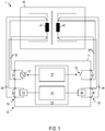
- Figure 1 shows a system 1 with a transformer testing device 10 according to an embodiment.
- the system 1 comprises a transformer 40 and the transformer testing device 10.
- the transformer testing device 10 can be designed as a single device with a housing 11.
- the transformer test apparatus 10 can consist of an arrangement of several devices or devices. In this case, the multiple devices or devices can be controlled by a central controller.
- the transformer testing device 10 can be designed as a mobile device and in particular as a portable device. If the transformer testing device 10 consists of several devices, each of the devices can be designed as a portable device.
- the transformer 40 can be a power transformer of an electrical energy supply device.
- the transformer 40 can be permanently installed in a power station or substation, while a transformer test is carried out with the transformer testing device 10.
- the transformer 40 can be a voltage converter or a current converter.
- the transformer 40 can be a voltage converter or a current converter which works according to the inductive operating principle.
- the transformer 40 comprises at least a first winding 41 and a second winding 42. It does not matter whether the first winding 41 is the primary winding and the second winding 42 is the secondary winding or vice versa. It is also irrelevant whether the first winding 41 is the high-voltage winding and the second winding 42 is the low-voltage winding, or vice versa.
- the transformer testing device 10 comprises several connections 12, a source 13 for a test signal that is applied to or impressed on the transformer 40 as a test object during the transformer test, and a controllable switching means 15.
- the controllable switching means 15 can, for example, be a relay, an IGBT or an FET be.
- the source 13 can be a current source which is controllable in order to generate a direct current and / or an alternating current as a test signal.
- the source 13 can be controllable in order to generate alternating currents with several different frequencies as a test signal.
- the source 13 can be a voltage source which can be controlled in order to generate a direct voltage and / or an alternating voltage as a test signal.
- the source 13 can be controllable in order to generate alternating voltages with several different frequencies as a test signal.
- the source 13 can be operated in different operating modes, for example as a current source or as a voltage source and / or as a source of a signal that is constant over time or an alternating signal.
- the source 13 can comprise a current measuring device.
- the source 13 can be set up to use an output signal of the current measuring device in a control loop for current control. Alternatively or additionally, a current measuring device can be connected in series with the source 13.
- the transformer test device 10 can comprise further devices, for example one or more measuring devices 14, 16 for detecting a test response in response to the test signal.
- the transformer testing device 10 can comprise a control device 17 for the automatic electrical control of the controllable switching means 15.
- the transformer test device 10 can comprise an evaluation device 18 for evaluating a test response of the transformer 40, which is recorded with the measuring devices 14, 16.
- the first measuring device 14 and the second measuring device 16 can each be set up for a voltage measurement, for example.
- the first measuring device 14 and the second measuring device 16 can each be set up to record other electrical parameters.
- the functions of the control device 17 and / or the evaluation device 18 can be carried out by a processor 19 or another integrated semiconductor circuit 19.
- the source 13 can generate a test signal that varies over time.
- a frequency of the test signal can be changed between several values.
- the first measuring device 14 and the second measuring device 16 can be used for time-resolved acquisition a test response must be set up.
- Measured values that are recorded by the first measuring device 14 and the second measuring device 16 can be A / D-converted and further computationally evaluated, for example in order to determine parameters of the transformer for each of several frequencies.
- the ports 12 include output ports 31 coupled to the source 13.
- the output connections 31 are electrically conductively connected to the first winding 41 of the transformer 40 via one or more lines 35.
- the terminals 12 include input terminals 32, 34 connected to one or more windings of the transformer via one or more lines 36, 38 to detect a test response of the transformer 10.
- a measuring device 14 can, for example, be connected to the first winding 41 via further lines 37 separate from the lines 35.
- the measuring device 14 can be a voltmeter.
- Such a connection between the transformer testing device 10 and the transformer 40 allows, for example, a measurement using what is known as a four-wire method.
- the separate routing of voltage lines from the input connection 32 to the first winding 41 can ensure that a voltage drop in the line 31 between the output connection 31 and the first winding 41 does not falsify the measurement result.
- the transformer testing device 10 comprises at least one pair of connections 33, which can be short-circuited via the controllable switching means 15.
- the controllable switching means can be a conventional switch, a mechanical-electrical switch, a relay, an FET, an IGBT or another component which is suitable for establishing an electrically conductive connection between the connections 33 depending on a state of the switching means.
- the conductive path in the transformer test apparatus 10 between the terminals 33 has an impedance which is less than an impedance of the winding 42 at at least one frequency or all frequencies with which the test signal is generated by the source 13 to which the pair of terminals 33 are connected via lines 37.
- the second winding 42 can also be connected to the connections 12 of the transformer testing device 10 via at least four lines 37, 38.
- the input terminals 34 can include a voltage input 34 which can be connected to a further voltmeter in order to connect it to the second winding 42 of the transformer 40 to be connected can be connected. Because the lines 37 and 38 are routed separately, falsification of the measurement results due to a possible voltage drop on the line 37 between the pair of connections 33 and the second winding 42 can be prevented.
- the transformer 40 can also include more than two windings 41, 42.
- the transformer testing device 10 can include connections for connection to a third winding of the transformer 40 and any further windings of the transformer 40.
- the transformer tester 10 may include terminals for connection to each winding of the transformer 40 for a four-wire measurement.
- the transformer testing device 10 can also comprise at least one second controllable switch 15 in order to short-circuit the first winding 41 or further windings of the transformer 40 when these are connected to the transformer testing device 10.
- the transformer test apparatus 10 can be configured to short-circuit combinations of two windings. For example, two of three windings of a transformer can be short-circuited simultaneously or sequentially. Test procedures can also be run automatically in which only one of several windings of the transformer is initially short-circuited and then two or more than two windings are short-circuited simultaneously or sequentially. The short-circuiting can in each case be carried out automatically by a controllable switching means of the transformer testing device 10.
- the transformer testing device 10 is set up in such a way that different measurements can be carried out without the connections 35-38 between the transformer testing device 10 and the transformer 40 having to be detached and / or otherwise connected.
- the various measurements can be carried out without the device under test having to be rewired.
- the measurements can be carried out by the transformer test device 10 in a fully or partially automated manner, i.e. without user interaction between the measurements.
- the controllable switching means 15 can short-circuit at least one of the windings of the transformer 40.
- the transformer testing device 10 can carry out a translation measurement.
- the source 13 can be operated as an alternating voltage source.
- the switch 15 can be open.
- a voltage on the first winding 41 can be detected with the first measuring device 14.
- a voltage on the second winding 42 can be detected with the second measuring device 16.
- the transformation ratio can be determined by the transformer testing device 10 from a ratio of the voltages.
- the transformer testing device 10 can alternatively or additionally be set up to carry out a short-circuit impedance measurement.
- the source 13 can be operated as an alternating current source.
- the switch 15 can be closed. This can be done by a control signal from the control device 17.
- the voltage on the first winding 41 can be detected with the first measuring device 14.
- a current in the second winding 42 can optionally be detected.
- the detected current in the second winding 42 can be used by the evaluation device 18 for correction purposes. For example, an error that arises due to a resistance of the lines 37, 38 from the second winding 42 to the test device 10 can be at least partially corrected.
- the transformer testing device 10 can alternatively or additionally be set up to carry out a winding resistance measurement.
- the resistance measurement can be a static resistance measurement.
- the winding resistance of the first winding 41 can be determined.
- the source 13 can operate as a direct current source.
- the voltage on the first winding 41 can be measured by the first measuring device 14.
- the direct current can be impressed until an iron core of the transformer 40 saturates.
- the controllable switching means 15 can be opened in order to reach the state in which the iron core is saturated more quickly.
- the controllable switching means 15 can be controlled in such a way that it is closed in order to short-circuit the second winding 42 when a winding resistance measurement, a short-circuit impedance measurement, a leakage impedance measurement or other measurements are carried out after the transformer core is saturated.
- a voltage at the second winding 42 can also be measured with the second measuring device 16 and used to correct errors, for example due to line resistances.
- the transformer testing device 10 can alternatively or additionally be set up to detect a behavior of the transformer 30 at the moment the transmission ratio is switched. Such a measurement is also referred to as a dynamic resistance measurement.
- the controllable switch 15 can in each case be closed at least when the changeover of the transmission ratio takes place. As a result, the effects detected at the first winding 14, which are caused by the switching process, can be intensified.
- the transformer testing device 10 can be carried out without the connections between the transformer testing device 10 and the transformer 40 having to be changed by user intervention for this purpose.
- the multiple measurements can be carried out without the connection points of the connections 35-38 on the transformer 40 and on the connections 12 of the transformer testing device 10 having to be changed.
- the control device 17 can be set up to control the controllable switching means 15 electrically.
- the control device 17 can switch the controllable switching means 15 to a closed state during part of a transformer test or during the entire transformer test in order to short-circuit the second winding 42.
- the transformer testing device 10 can be set up to carry out several different measurements sequentially, it being possible for the measurements and optionally also their sequence to be defined in a user-defined manner.
- the transformer testing device 10 can comprise a graphical user interface with which it is possible to define in a user-defined manner which measurements are carried out.
- the controllable switching means 15 and the source 13 can be controlled as a function of time in such a way that the selected measurements are carried out. It is also possible to select only a single measurement, for example a measurement of the transmission ratio or a winding resistance measurement or a leakage impedance measurement.
- the transformer testing device 10 then switches the controllable switching means 15 according to the selected measurement.
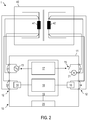
- FIG. 2 is an illustration of a system 1 with a transformer testing device 10 according to a further embodiment.
- the transformer testing device 10 comprises a graphical user interface 20.
- the graphical user interface 20 can be set up to allow a user-defined definition of measurements that are carried out with the transformer testing device 10.
- the controllable switching means 15 can be switched once or several times during the transformer test. The switching of the controllable switching means 15 can take place automatically under the control of the control device 17 without requiring a user input or other user action after the transformer test has been started.
- the transformer testing device 10 shown also has an ammeter 21 which is connected in series with the controllable switching means 15.
- the ammeter 21 may have an internal resistance that is much smaller than an impedance of the second winding 42 to which the terminals 33 are connected.
- An output signal of the ammeter 21 can be evaluated by the evaluation device 18, for example in order to correct the voltages detected by the measuring devices 14, 16.
- FIG 3 is an illustration of a system 1 with a transformer testing device 10 according to a further embodiment.
- the measuring devices 14, 16 are designed as voltmeters in order to detect a voltage drop across the first winding 41 and the second winding 42.
- Other configurations of the measuring devices 14, 16 can be used.
- FIG. 3 is a flow diagram of a method 50 according to an embodiment.
- the method 50 can be carried out automatically by the transformer testing device 10 according to one exemplary embodiment.
- a selection of a test procedure can take place.
- the testing procedure may include one or more measurements performed on the transformer 40.
- the test procedure can be selected in a user-defined manner from a plurality of test procedures.
- controllable switching means 15 is controlled as a function of the selected test procedure.
- the controllable switching means 15 can be automatically controlled so that one winding of the transformer 40 during the entire Test procedure or during part of the test procedure is short-circuited. A short-circuit current of the winding flows through the transformer testing device 10.
- the source for generating the test signal is controlled.
- the source can be controlled in such a way that it optionally generates a direct current, a direct voltage or an alternating voltage.
- Different test signals can also be generated as a function of time.
- the activation of the source and the activation of the controllable switch can be coordinated with one another in terms of time.
- the controllable switching means can be controlled in each case so that the second winding 42 is not short-circuited while the source impresses a direct current on the first winding 41.
- a test response of the transformer 40 can be evaluated automatically.
- the evaluation can include the determination of a winding resistance in a static resistance measurement, the determination of a leakage impedance, the determination of a leakage inductance, the determination of a transmission ratio or the determination of a combination of two or more than two of these parameters.
- controllable switching means 15 can be switched one or more times.
- FIG. 5 and Figure 6 illustrate by way of example a control signal Ctrl_s for controlling the controllable switching means 15 during a test procedure.
- the control signal can be generated automatically by a semiconductor integrated circuit of the transformer test apparatus 10.
- the control signal can be generated automatically by an integrated semiconductor circuit of the transformer testing device 10 in accordance with a time schedule or as a function of an output signal from at least one of the measuring devices 14, 16, 21 of the transformer testing device 10.
- Figure 5 illustrates a control signal 60 for activating the controllable switching means 15 during a test procedure which can be carried out by the transformer test device 10.
- the duration of the examination procedure has the control signal 60 has a first value and the controllable switching means 15 is open, so that the controllable switching means 15 does not short-circuit the winding 42.
- the controllable switching means 15 is switched to the closed state in order to short-circuit the second winding 42.
- the control signal 60 is changed to a second value.
- the controllable switching means is closed in order to short-circuit the second winding 42.
- the point in time at which the controllable switching means 15 is closed can be established, for example, by a time schedule or can depend on a condition. For example, saturation of the transformer core can be monitored.
- the controllable switching means 15 can be closed when the transformer core is completely saturated or when the saturation fulfills a predetermined criterion.
- Figure 6 illustrates a control signal 65 for controlling the controllable switching means 15 during a test procedure which can be carried out by the transformer test device 10.
- the controllable switching means 15 is switched several times into the closed and the open state while the test procedure is being carried out. For example, in a part 66 of the test procedure, the controllable switching means 15 can be open in each case, so that the second winding 42 is not short-circuited. In another part 67 of the test procedure, the controllable switching means 15 can be closed, so that the second winding 42 is short-circuited.
- the point in time at which the controllable switching means 15 is closed and opened in each case can be established, for example, by a time schedule or can depend on a condition, as with reference to FIG Figure 5 has been described.
- the transformer testing device 10 can comprise a plurality of controllable switching means.
- the control signals for the several controllable switching means can be generated in a time-coordinated manner in order to run a test procedure in which either one winding or several windings of the transformer are short-circuited without having to rewiring.
- FIG 7 is an illustration of a system 1 with a transformer test apparatus 10 according to an embodiment.
- the transformer 40 is set up so that a transformation ratio can be changed.
- the transformer 40 can comprise, for example, a tap changer 43 which has a first winding 41.
- the structure and mode of operation of the tap changer 43 are known to those skilled in the art.
- the transformer testing device 10 can be set up to monitor and evaluate a behavior of the transformer 40 during the switchover of the tap changer 43.
- the transformer testing device 10 can in particular be set up for a dynamic resistance measurement.
- a winding resistance of the tap changer 43 between the two connections of the tap changer when switching can be determined.
- a direct current or alternating current can be impressed by the source 13 and a voltage drop across the tap changer 41 can be detected with the measuring device 14.
- the controllable switching means 15 is set up to selectively short-circuit the second winding 42 on the side of the transformer 40 on which no tap changer is provided.
- the controllable switching means 15 can be closed when the step switch 41 is switched over in order to short-circuit the second winding 42. In this way, particularly clear effects can be observed during the switchover process.
- the controllable switching means 15 can be opened between two processes, so that the second winding 42 is not short-circuited. As a result, the behavior of the transformer 40 can be stabilized more quickly.
- a static resistance measurement can also be carried out for each switching stage of the tap changer 41, in which the resistance of the tap changer 41 is determined for one or more frequencies.
- the transformer testing device 10 can comprise an interface in order to carry out the switching of the controllable switching means 15 in a coordinated manner with switching operations of the tap changer 41.
- the transformer testing device 10 can be set up to trigger switching operations of the tap changer 41.
- the transformer testing device 10 can start a switching process by monitoring the voltage at the tap changer are automatically recognized and can serve as a trigger for an automatic switching of the controllable switching means 15 into the closed state.
- FIG. 7 is a flow diagram of a method 70 according to an embodiment.
- the method 70 can be carried out automatically by the transformer testing device 10 for testing a transformer comprising a tap changer.
- the transformer testing apparatus 10 is detachably connected to the transformer 40.
- the tap changer can be brought into an initial position which, for example, can correspond to a maximum self-inductance of the tap changer.
- the behavior of the transformer 40 can then be automatically recorded each time the tap changer 43 is switched over.
- a static resistance measurement can be carried out for each switching stage of the tap changer 43 in order to determine the winding resistance of the tap changer 43.
- other measurements can be made between the switching operations of the tap changer 43.
- step 73 the controllable switching means 15 can be in a state in which the second winding 42 is not short-circuited. This enables the transformer to stabilize more quickly if a direct current is impressed on the primary side.
- a resistance measurement can be made.
- a winding resistance of the tap changer 43 can be determined.
- step 75 the controllable switching means 15 can be activated in such a way that it is closed in order to short-circuit the second winding 42.
- step 76 the step switch 43 can be actuated so that a switchover process between different switching steps is triggered.
- the voltage at the step switch 43 can be measured.
- the source 13 can, for example, impress a direct current. From the captured Voltage, a dynamic resistance can be determined during the switching process.
- step 77 it can be checked whether the last step of the step switch 43 has been reached.
- the last stage can, for example, be the stage in which the tap changer 43 has the lowest self-inductance. If the last shift stage has not yet been reached, the method can return to step 73.
- the controllable switching means 15 can be opened in order not to short-circuit the second winding 42.
- the transformer test device can be disconnected from the transformer in step 78.
- An automatic further evaluation and / or archiving of the results of the transformer test can be carried out by the transformer test device.
- the transformer testing device can comprise only one controllable switching means for short-circuiting only one winding of the transformer, the transformer testing device can also have two or more than two controllable switching means for short-circuiting several turns of the transformer.
- the transformer testing device can be set up to short-circuit a plurality of windings simultaneously or in a time-sequential manner.
- the transformer test device can be set up to short-circuit a low-voltage side of a transformer
- the transformer test device can also be set up to short-circuit the high-voltage side or a tertiary winding of the transformer with the controllable switching means as an alternative or in addition to the low-voltage side.
- the transformer test device and the method according to exemplary embodiments can also be used if only one characteristic of the transformer is measured before a new user input is required.
- the transformer can be installed in a power station or substation of an energy supply network
- the transformer testing device and the method according to the exemplary embodiments can also be used with smaller transformers.
- Transformer testing device methods and systems according to exemplary embodiments allow further automation in transformer testing.
Description
Die Erfindung betrifft eine Transformatorprüfvorrichtung nach Anspruch 1 und ein Verfahren zum Prüfen von Transformatoren nach Anspruch 8.The invention relates to a transformer testing device according to claim 1 and a method for testing transformers according to claim 8.
Die Erfindung betrifft insbesondere derartige Vorrichtungen und Verfahren, bei denen wenigstens während eines Teils einer Transformatorprüfung eine Wicklung des Transformators kurzgeschlossen wird.The invention relates in particular to such devices and methods in which a winding of the transformer is short-circuited at least during part of a transformer test.
In der Broschüre "
Die Druckschrift
Transformatoren werden als Bestandteile von Energieversorgungsnetzen verwendet. Transformatoren können zur Spannungswandlung von einem ersten Wert an einer Oberspannungsseite zu einem zweiten Wert, der kleiner als der erste Wert ist, an einer Unterspannungsseite eingesetzt werden.Transformers are used as components of power supply networks. Transformers can be used for voltage conversion from a first value on a high-voltage side to a second value, which is smaller than the first value, on a low-voltage side.
Die Bestimmung von Eigenschaften eines Transformators durch eine Transformatorprüfung, bei der eine oder mehrere charakteristische Kenngrößen des Transformators durch Messung ermittelt werden, ist beispielsweise zur Gewährleistung der Betriebssicherheit, zur Ansteuerung oder aus weiteren Gründen erforderlich. Beispiele für derartige Transformatorprüfungen beinhalten die Bestimmung eines statischen Widerstands, die Bestimmung eines dynamischen Widerstands, die Bestimmung eines Übersetzungsverhältnisses und/oder die Bestimmung einer Streuimpedanz oder Streuinduktivität. Bei einer statischen Widerstandsmessung kann ein Gleichstrom in eine Wicklung des Transformators eingespeist werden, und die Spannung kann gemessen werden. Bei einer dynamischen Widerstandsmessung kann das Übersetzungsverhältnis des Transformators mit einem Stufenschalter während der Messung umgeschaltet werden. Eine Spannung, ein Strom und/oder ein Widerstand können erfasst und ausgewertet werden. Aus dem Verlauf der gemessenen Parameter können beispielsweise Rückschlüsse auf einen Zustand des Stufenschalters gezogen werden.The determination of properties of a transformer by a transformer test, in which one or more characteristic parameters of the transformer are determined by measurement, is necessary, for example, to ensure operational safety, for control or for other reasons. Examples of such transformer tests include the determination of a static resistance, the determination of a dynamic resistance, the determination of a transmission ratio and / or the determination of a leakage impedance or leakage inductance. In a static resistance measurement, a direct current can be fed into a winding of the transformer and the voltage can be measured. With a dynamic resistance measurement, the transformation ratio of the transformer can be set with a step switch during the measurement be switched. A voltage, a current and / or a resistance can be recorded and evaluated. From the course of the measured parameters, for example, conclusions can be drawn about a state of the tap changer.
Bei wenigstens einem Teil einer Transformatorprüfung kann eine Wicklung des Transformators, beispielsweise eine Wicklung auf der Unterspannungsseite, kurzgeschlossen werden. Dies erfordert herkömmlich eine Umverdrahtung im Sinne eines händischen Eingriffs, mit dem elektrisch leitende Verbindungen anders angeschlossen werden müssen, um einen Abschnitt der Transformatorprüfung auszuführen, bei dem eine Wicklung kurzgeschlossen ist. Dies führt zu zusätzlichem Arbeits- und Zeitaufwand. Insbesondere bei Transformatoren, wie sie in Kraftwerken oder Umspannwerken verwendet werden, können diese Umverdrahtungen sehr aufwändig sein. Häufig werden Leitern oder Steiger benötigt.In at least one part of a transformer test, a winding of the transformer, for example a winding on the low-voltage side, can be short-circuited. This conventionally requires rewiring in the sense of manual intervention, with which electrically conductive connections have to be connected differently in order to carry out a section of the transformer test in which a winding is short-circuited. This leads to additional work and time expenditure. In particular in the case of transformers such as those used in power stations or substations, this rewiring can be very complex. Often ladders or risers are required.
Es besteht ein Bedarf an Vorrichtungen und Verfahren, mit denen eine Transformatorprüfung weiter automatisiert werden kann. Es besteht insbesondere ein Bedarf an Vorrichtungen und Verfahren, mit denen eine Transformatorprüfung weiter automatisiert werden kann und der mit Umverdrahtungen verbundene Arbeitsaufwand verringert werden kann.There is a need for devices and methods with which transformer testing can be further automated. In particular, there is a need for devices and methods with which a transformer test can be further automated and the amount of work associated with rewiring can be reduced.
Erfindungsgemäß werden eine Transformatorprüfvorrichtung und ein Verfahren zum Prüfen eines Transformators angegeben, bei denen die Transformatorprüfvorrichtung eingerichtet ist, um wenigstens eine Wicklung des Transformators kurzzuschließen. Die Transformatorprüfvorrichtung kann ein steuerbares Schaltmittel umfassen, das betätigt wird, um einen Kurzschlussstrom vom Transformator durch das steuerbare Schaltmittel der Transformatorprüfvorrichtung fließen zu lassen.According to the invention, a transformer testing device and a method for testing a transformer are specified, in which the transformer testing device is set up to short-circuit at least one winding of the transformer. The transformer testing device can comprise a controllable switching means which is actuated to allow a short-circuit current from the transformer to flow through the controllable switching means of the transformer testing device.
Bei der Transformatorprüfvorrichtung und dem Verfahren nach Ausführungsbeispielen kann die wenigstens eine Wicklung während eines Teils einer Transformatorprüfung kurzgeschlossen werden. Die wenigstens eine Wicklung kann während der gesamten Transformatorprüfung kurzgeschlossen werden. Das steuerbare Schaltmittel kann bei Ausführung der Transformatorprüfung automatisch so angesteuert werden, dass zeitabhängig das Fließen eines Kurzschlussstroms durch die Transformatorprüfung erlaubt wird. Das steuerbare Schaltmittel kann bei Ausführung der Transformatorprüfung automatisch so angesteuert werden, dass zeitabhängig das Fließen eines Kurzschlussstroms durch die Transformatorprüfung erlaubt und dann wieder unterbunden wird, um unterschiedliche Messungen auszuführen.In the transformer test device and the method according to exemplary embodiments, the at least one winding can be short-circuited during part of a transformer test. The at least one winding can be short-circuited during the entire transformer test. When the transformer test is carried out, the controllable switching means can be activated automatically in such a way that a short-circuit current is allowed to flow through the transformer test in a time-dependent manner. The controllable switching means can be used when carrying out the transformer test can be controlled automatically in such a way that, depending on the time, a short-circuit current is allowed to flow through the transformer test and then prevented again in order to carry out different measurements.
Die Transformatorprüfvorrichtung hat Anschlüsse, die mit einer Unterspannungsseite des Transformators zu verbinden sind. Die Transformatorprüfvorrichtung kann so eingerichtet sein, dass das steuerbare Schaltmittel den Widerstand zwischen wenigstens zwei der mit der Unterspannungsseite zu verbindenden Anschlüssen verringert, um die wenigstens eine Wicklung an der Unterspannungsseite des Transformators kurzzuschließen. Die Transformatorprüfvorrichtung kann eingerichtet sein, um alternativ oder zusätzlich zur Unterspannungsseite die Oberspannungsseite oder eine Tertiärwicklung des Transformators mit dem steuerbaren Schaltmittel kurzzuschließen. Die Transformatorprüfvorrichtung kann eingerichtet sein, um Kombinationen von zwei Wicklungen kurzzuschließen. Beispielsweise kann die Transformatorprüfvorrichtung eingerichtet sein, um zwei von drei Wicklungen eines Transformators automatisch kurzzuschließen.The transformer testing device has connections that are to be connected to a low voltage side of the transformer. The transformer testing device can be set up such that the controllable switching means reduces the resistance between at least two of the connections to be connected to the low voltage side in order to short-circuit the at least one winding on the low voltage side of the transformer. The transformer testing device can be set up to short-circuit the high-voltage side or a tertiary winding of the transformer with the controllable switching means as an alternative or in addition to the low-voltage side. The transformer test apparatus can be configured to short-circuit combinations of two windings. For example, the transformer testing device can be set up to automatically short-circuit two of three windings of a transformer.
Unter einem Kurzschließen wird hier die Herstellung eines elektrisch leitenden Pfads mit einem geringen Widerstand verstanden. Der elektrisch leitende Pfad kann nahe an der Wicklung des Transformators eine nahezu perfekte elektrische Verbindung herstellen. Es kann auch eine Strommesseinrichtung, beispielsweise ein Amperemeter, in den Pfad über Verbindungsleitungen eingeschleift sein. Durch Leitungswiderstände und den Innenwiderstand des Amperemeters ist der Kurzschluss zwar nicht perfekt, aber kann deutlich von einem Leerlauf oder einem Leerlauf mit angeschlossenem Voltmeter unterschieden werden.Short-circuiting is understood here to mean the creation of an electrically conductive path with a low resistance. The electrically conductive path can make a near perfect electrical connection close to the winding of the transformer. A current measuring device, for example an ammeter, can also be looped into the path via connecting lines. The short circuit is not perfect due to line resistances and the internal resistance of the ammeter, but it can be clearly distinguished from an open circuit or an open circuit with a connected voltmeter.
Die Transformatorprüfvorrichtung ist eingerichtet, um automatisch während eines Prüfablaufs den Kurzschluss zeitweise anzulegen und zeitweise den Kurzschluss zu öffnen. So kann beispielsweise eine Quelle für ein Prüfsignal an der Primärwicklung des Transformators eine Wechselspannung anlegen und dann, wenn auf der Sekundärseite der Kurzschluss erzeugt ist, eine Kurzschlussimpedanz messen. Wenn der Kurzschluss unterbrochen ist, kann durch Messung der Spannung auf Primär- und Sekundärseite das Übersetzungsverhältnis des Transformators.The transformer testing device is set up to automatically apply the short circuit temporarily during a test sequence and to temporarily open the short circuit. For example, a source for a test signal can apply an alternating voltage to the primary winding of the transformer and then measure a short-circuit impedance when the short circuit is generated on the secondary side. If the short circuit is interrupted, the transformation ratio of the transformer can be determined by measuring the voltage on the primary and secondary side.
Der Kurzschluss kann von der Transformatorprüfvorrichtung an der Unterspannungsseite oder Sekundärseite des Transformators hergestellt werden. Transformatorprüfvorrichtungen und Verfahren nach Ausführungsbeispielen erlauben die Durchführung von Messungen, bei denen wenigstens eine Wicklung während wenigstens eines Teils der Transformatorprüfung kurzgeschlossen wird, ohne dass dafür spezifisch die Verbindungen zwischen dem Transformator und der Transformatorprüfvorrichtung geändert werden müssen. Der mit Umverdrahtungen verbundene Arbeitsaufwand kann verringert oder beseitigt werden.The short circuit can be established by the transformer tester on the low voltage side or the secondary side of the transformer. Transformer test devices and methods according to exemplary embodiments allow measurements to be carried out in which at least one winding is short-circuited during at least part of the transformer test without specifically having to change the connections between the transformer and the transformer test device. The labor associated with rewiring can be reduced or eliminated.
Eine Transformatorprüfvorrichtung zum Prüfen eines Transformators nach der Erfindung umfasst Anschlüsse zur lösbaren Verbindung der Transformatorprüfvorrichtung mit dem Transformator. Die Transformatorprüfvorrichtung umfasst eine Quelle zum Erzeugen eines Prüfsignals zum Prüfen des Transformators. Die Transformatorprüfvorrichtung umfasst ein steuerbares Schaltmittel, das zum Kurzschließen wenigstens einer Wicklung des Transformators bei einer Transformatorprüfung mit den Anschlüssen verbunden ist.A transformer testing device for testing a transformer according to the invention comprises connections for releasably connecting the transformer testing device to the transformer. The transformer test apparatus includes a source for generating a test signal for testing the transformer. The transformer testing device comprises a controllable switching means which is connected to the connections for short-circuiting at least one winding of the transformer during a transformer test.
Die Transformatorprüfvorrichtung umfasst eine Steuereinrichtung, die mit dem steuerbaren Schaltmittel verbunden ist. Die Steuereinrichtung ist eingerichtet, um das steuerbare Schaltmittel zur Durchführung der Transformatorprüfung wenigstens einmal automatisch zu betätigen. Die Steuereinrichtung kann eine oder mehrere integrierte Halbleitschaltungen umfassen.The transformer testing device comprises a control device which is connected to the controllable switching means. The control device is set up to automatically actuate the controllable switching means at least once to carry out the transformer test. The control device can comprise one or more integrated semiconductor circuits.
Die Steuereinrichtung ist eingerichtet, um das steuerbare Schaltmittel gemäß einem Zeitablaufplan, der von einer ausgewählten Prüfungsprozedur abhängt, automatisch zeitabhängig anzusteuern.The control device is set up to automatically control the controllable switching means in a time-dependent manner in accordance with a time schedule which depends on a selected test procedure.
Die Transformatorprüfvorrichtung kann eine Benutzerschnittstelle zum Auswählen der Prüfungsprozedur aus einer Mehrzahl von Prüfungsprozeduren umfassen.The transformer test apparatus may include a user interface for selecting the test procedure from a plurality of test procedures.
Die Steuereinrichtung ist eingerichtet um das steuerbare Schaltmittel und die Quelle gemäß dem Zeitablaufplan zeitabhängig anzusteuern.The control device is set up to control the controllable switching means and the source in a time-dependent manner in accordance with the time schedule.
Die Transformatorprüfvorrichtung kann als ein mobiles Transformatorprüfgerät ausgestaltet sein. Die Transformatorprüfvorrichtung kann als ein portables Transformatorprüfgerät ausgestaltet sein. Die Transformatorprüfvorrichtung kann ein Gehäuse umfassen, in dem die Quelle und das steuerbare Schaltmittel untergebracht sind. Die Anschlüsse können an dem Gehäuse vorgesehen sein.The transformer testing device can be designed as a mobile transformer testing device. The transformer testing device can be designed as a portable transformer testing device. The transformer test apparatus may comprise a housing in which the source and the controllable switching means are housed. The connections can be provided on the housing.
Das steuerbare Schaltmittel kann im Inneren des Gehäuses angeordnet sein.The controllable switching means can be arranged in the interior of the housing.
Das steuerbare Schaltmittel kann zum Leiten eines Kurzschlussstroms bei der Transformatorprüfung eingerichtet sein.The controllable switching means can be set up to conduct a short-circuit current during the transformer test.
Die Transformatorprüfvorrichtung kann eine Strommesseinrichtung, beispielsweise ein Amperemeter, umfassen, das mit dem steuerbaren Schaltmittel in Reihe geschaltet ist.The transformer testing device can comprise a current measuring device, for example an ammeter, which is connected in series with the controllable switching means.
Die Transformatorprüfvorrichtung kann eingerichtet sein, um die wenigstens eine Wicklung während eines Teils einer Zeitdauer der Transformatorprüfung kurzzuschließen. Während der Transformatorprüfung kann der Kurzschluss zeitabhängig hergestellt und aufgehoben werden.The transformer test device can be set up to short-circuit the at least one winding during part of a period of time of the transformer test. During the transformer test, the short circuit can be created and removed depending on the time.
Die Transformatorprüfvorrichtung kann eingerichtet sein, um die wenigstens eine Wicklung während einer gesamten Zeitdauer der Transformatorprüfung kurzzuschließenThe transformer testing device can be set up to short-circuit the at least one winding during the entire duration of the transformer testing
Die Transformatorprüfvorrichtung kann eingerichtet sein, um bei der Transformatorprüfung wenigstens eine Widerstandsmessung auszuführen. Alternativ oder zusätzlich kann die Transformatorprüfvorrichtung eingerichtet sein, um bei der Transformatorprüfung wenigstens eine einer Streuimpedanzmessung auszuführen. Alternativ oder zusätzlich kann die Transformatorprüfvorrichtung eingerichtet sein, um bei der Transformatorprüfung wenigstens eine dynamische Widerstandsmessung bei Betätigung eines Stufenschalters auszuführen.The transformer test device can be set up to carry out at least one resistance measurement during the transformer test. Alternatively or additionally, the transformer test device can be set up to carry out at least one leakage impedance measurement during the transformer test. As an alternative or in addition, the transformer test device can be set up to carry out at least one dynamic resistance measurement when a tap changer is operated during the transformer test.
Die Transformatorprüfvorrichtung kann eine Messeinrichtung umfassen, um eine Prüfantwort des Transformators auf das Prüfsignal zu erfassen. Die Messeinrichtung kann ein Voltmeter und/oder ein Amperemeter umfassen. Die Transformatorprüfvorrichtung kann einen Prozessor oder eine andere elektronische Verarbeitungseinrichtung aufweisen, die eingerichtet ist, um eine von der Messeinrichtung während der Transformatorprüfung erfasste Prüfantwort weiter zu verarbeiten.The transformer test device can comprise a measuring device in order to detect a test response of the transformer to the test signal. The measuring device can comprise a voltmeter and / or an ammeter. The transformer test device can have a processor or some other electronic processing device which is set up to further process a test response recorded by the measuring device during the transformer test.
Das Prüfsignal kann ein Strom sein, der in den Transformator eingeprägt wird. Die mit der Messeinrichtung erfasste Prüfantwort kann eine Spannung sein, die in einer Vierpunkt-Messung erfasst wird.The test signal can be a current that is impressed on the transformer. The test response recorded with the measuring device can be a voltage which is recorded in a four-point measurement.
Das Prüfsignal kann eine Spannung sein, die an den Transformator angelegt wird. Die mit der Messeinrichtung erfasste Prüfantwort kann ein Strom sein.The test signal can be a voltage that is applied to the transformer. The test response recorded with the measuring device can be a current.
Die Transformatorprüfvorrichtung kann eingerichtet sein, um für eine statische Widerstandsmessung die wenigstens eine Wicklung nicht kurzzuschließen, bis ein Kern des Transformators in Sättigung gegangen ist. Die Transformatorprüfvorrichtung kann eingerichtet sein, um durch Betätigung des steuerbaren Schalters die wenigstens eine Wicklung anschließend kurzzuschließen, um die Widerstandsmessung auszuführen.The transformer testing device can be set up in order not to short-circuit the at least one winding for a static resistance measurement until a core of the transformer has gone into saturation. The transformer testing device can be set up to then short-circuit the at least one winding by actuating the controllable switch in order to carry out the resistance measurement.
Die Transformatorprüfvorrichtung kann eingerichtet sein, um einen Wicklungswiderstand des Transformators zu messen.The transformer testing device can be set up to measure a winding resistance of the transformer.
Die Transformatorprüfvorrichtung kann eingerichtet sein, eine Messung an dem Transformator bei einer Betätigung eines Stufenschalters des Transformators auszuführen. Die Messung kann eine dynamische Widerstandsmessung während eines Schaltvorgangs des Stufenschalters sein. Dabei kann die Transformatorprüfvorrichtung eine Veränderung von Strom, Spannung und/oder Widerstand während des Schaltens des Stufenschalters erfassen. Vorteilhaft kann die Transformatorprüfvorrichtung eingerichtet sein, um den Transformator an einer anderen Wicklung als der Stufenschalterwicklung kurzzuschließen, um die Veränderungen der elektrischen Größen zu verstärken.The transformer testing device can be set up to carry out a measurement on the transformer when a tap changer of the transformer is actuated. The measurement can be a dynamic resistance measurement during a switching process of the tap changer. The transformer testing device can detect a change in current, voltage and / or resistance during the switching of the tap changer. The transformer testing device can advantageously be set up to short-circuit the transformer to a winding other than the tap changer winding in order to amplify the changes in the electrical quantities.
Die Quelle der Transformatorprüfvorrichtung kann so ausgestaltet sein, dass sie selektiv als Stromquelle oder als Spannungsquelle betreibbar ist.The source of the transformer testing device can be designed in such a way that it can be operated selectively as a current source or as a voltage source.
Die Quelle kann eine Strommesseinrichtung umfassen. Die Quelle kann eingerichtet sein, um ein Ausgangssignal der Strommesseinrichtung in einer Regelschleife für eine Stromregelung zu verwenden. Alternativ oder zusätzlich kann eine Strommesseinrichtung mit der Quelle in Serie geschaltet sein.The source can comprise a current measuring device. The source can be set up to use an output signal of the current measuring device in a control loop for a current control. Alternatively or additionally, a current measuring device can be connected in series with the source.
Das steuerbare Schaltmittel kann ein Relais sein oder kann ein Relais umfassen. Das steuerbare Schaltmittel kann ein Bipolartransistor mit isolierter Gate-Elektrode (IGBT) oder ein Feldeffekttransistor (FET) sein oder kann einen IGBT oder einen FET umfassen.The controllable switching means can be a relay or can comprise a relay. The controllable switching means can be a bipolar transistor with an insulated gate electrode (IGBT) or a field effect transistor (FET) or can comprise an IGBT or an FET.
Ein System nach einem Ausführungsbeispiel umfasst einen Transformator und eine Transformatorprüfvorrichtung nach einem Ausführungsbeispiel, die über die Anschlüsse lösbar mit dem Transformator verbunden ist.A system according to an exemplary embodiment comprises a transformer and a transformer testing device according to an exemplary embodiment, which is detachably connected to the transformer via the connections.
Die Transformatorprüfvorrichtung kann so mit dem Transformator verbunden sein, dass über den steuerbaren Schalter der Transformatorprüfvorrichtung wenigstens eine Wicklung an der Unterspannungsseite oder Sekundärseite des Transformators kurzschließbar ist.The transformer testing device can be connected to the transformer in such a way that at least one winding on the low-voltage side or secondary side of the transformer can be short-circuited via the controllable switch of the transformer testing device.
Nach einem weiteren Ausführungsbeispiel wird ein Verfahren zum Prüfen eines Transformators mit einer Transformatorprüfvorrichtung angegeben. Die Transformatorprüfvorrichtung weist Anschlüsse zur lösbaren Verbindung der Transformatorprüfvorrichtung mit dem Transformator auf. Das Verfahren umfasst ein Kurzschließen wenigstens einer Wicklung des Transformators mit einem steuerbaren Schaltmittel der Transformatorprüfvorrichtung.According to a further exemplary embodiment, a method for testing a transformer with a transformer testing device is specified. The transformer testing device has connections for the detachable connection of the transformer testing device to the transformer. The method comprises short-circuiting at least one winding of the transformer with a controllable switching means of the transformer testing device.
Das Verfahren kann von der Transformatorprüfvorrichtung nach einem Ausführungsbeispiel ausgeführt werden. Das Verfahren kann von der Transformatorprüfvorrichtung nach einem Ausführungsbeispiel automatisch ausgeführt werden.The method can be carried out by the transformer testing device according to an exemplary embodiment. According to one exemplary embodiment, the method can be carried out automatically by the transformer testing device.
Bei dem Verfahren kann eine Steuereinrichtung, die mit dem steuerbaren Schaltmittel verbunden ist, das steuerbare Schaltmittel zur Durchführung der Transformatorprüfung wenigstens einmal automatisch zu betätigen.In the method, a control device, which is connected to the controllable switching means, can automatically actuate the controllable switching means at least once to carry out the transformer test.
Bei dem Verfahren kann das steuerbare Schaltmittel gemäß einem Zeitablaufplan, der von einer ausgewählten Prüfungsprozedur abhängt, automatisch zeitabhängig angesteuert werden.In the case of the method, the controllable switching means can be controlled automatically in a time-dependent manner in accordance with a time schedule which depends on a selected test procedure.
Das Verfahren kann das Erfassen einer Benutzereingabe an einer Benutzerschnittstelle umfassen, mit der die Prüfungsprozedur aus einer Mehrzahl von Prüfungsprozeduren ausgewählt wird.The method can include the acquisition of a user input at a user interface with which the test procedure is selected from a plurality of test procedures.
Bei dem Verfahren können das steuerbare Schaltmittel und die Quelle gemäß dem Zeitablaufplan zeitabhängig angesteuert werden.In the method, the controllable switching means and the source can be controlled in a time-dependent manner according to the time schedule.
Das Verfahren kann von einer Transformatorprüfvorrichtung ausgeführt werden, die als ein mobiles Transformatorprüfgerät ausgestaltet ist.The method can be carried out by a transformer testing device which is designed as a mobile transformer testing device.
Das Verfahren kann von einer Transformatorprüfvorrichtung ausgeführt werden, die als ein portables Transformatorprüfgerät ausgestaltet ist.The method can be carried out by a transformer testing device which is designed as a portable transformer testing device.
Das steuerbare Schaltmittel, das bei dem Verfahren geschaltet wird, kann in einem Inneren eines Gehäuses der Transformatorprüfvorrichtung angeordnet sein. In dem Gehäuse kann auch die Quelle angeordnet sein.The controllable switching means that is switched in the method can be arranged in an interior of a housing of the transformer testing device. The source can also be arranged in the housing.
Bei dem Verfahren kann das steuerbare Schaltmittel einen Kurzschlussstrom bei der Transformatorprüfung leiten.In the method, the controllable switching means can conduct a short-circuit current during the transformer test.
Bei dem Verfahren kann die wenigstens eine Wicklung während eines Teils einer Zeitdauer der Transformatorprüfung kurzgeschlossen werden. Während der Transformatorprüfung kann der Kurzschluss zeitabhängig hergestellt und aufgehoben werden.In the method, the at least one winding can be short-circuited during part of a duration of the transformer test. During the transformer test, the short circuit can be created and removed depending on the time.
Bei dem Verfahren kann die wenigstens eine Wicklung während einer gesamten Zeitdauer der Transformatorprüfung kurzgeschlossen werden.In the method, the at least one winding can be short-circuited during the entire duration of the transformer test.
Das Verfahren kann wenigstens eine Widerstandsmessung umfassen. Alternativ oder zusätzlich kann das Verfahren wenigstens eine Streuimpedanzmessung umfassen. Alternativ oder zusätzlich kann das Verfahren wenigstens eine dynamische Widerstandsmessung umfassen. Alternativ oder zusätzlich kann das Verfahren eine Messung eines Übersetzungsverhältnisses umfassen.The method can include at least one resistance measurement. Alternatively or additionally, the method can include at least one leakage impedance measurement. Alternatively or additionally, the method can include at least one dynamic resistance measurement. Alternatively or additionally, the method can include a measurement of a transmission ratio.
Bei dem Verfahren kann eine Prüfantwort des Transformators auf das Prüfsignal mit einer Messeinrichtung erfasst werden. Die Messeinrichtung kann ein Voltmeter und/oder ein Amperemeter umfassen. Die von der Messeinrichtung während der Transformatorprüfung erfasste Prüfantwort kann automatisch weiter verarbeitet werden.In the method, a test response of the transformer to the test signal can be recorded with a measuring device. The measuring device can comprise a voltmeter and / or an ammeter. The test response recorded by the measuring device during the transformer test can be processed further automatically.
Das Prüfsignal kann ein Strom sein, der in den Transformator eingeprägt wird. Die mit der Messeinrichtung erfasste Prüfantwort kann eine Spannung sein, die in einer Vierpunkt-Messung erfasst wird.The test signal can be a current that is impressed on the transformer. The test response recorded with the measuring device can be a voltage which is recorded in a four-point measurement.
Das Prüfsignal kann eine Spannung sein, die an den Transformator angelegt wird. Die mit der Messeinrichtung erfasste Prüfantwort kann ein Strom sein.The test signal can be a voltage that is applied to the transformer. The test response recorded with the measuring device can be a current.
Bei dem Verfahren kann ein Wicklungswiderstand des Transformators gemessen werden.In the method, a winding resistance of the transformer can be measured.
Bei dem Verfahren kann eine Messung an dem Transformator bei einer Betätigung eines Stufenschalters des Transformators erfolgen. Die Messung kann eine dynamische Widerstandsmessung während eines Schaltvorgangs des Stufenschalters sein. Dabei kann eine Veränderung von Strom, Spannung und/oder Widerstand während des Schaltens des Stufenschalters erfasst werden. Vorteilhaft kann der Transformator an einer anderen Wicklung als der Stufenschalterwicklung kurzgeschlossen werden, um die Veränderungen der elektrischen Größen zu verstärken.In the method, a measurement can be made on the transformer when a tap changer of the transformer is actuated. The measurement can be a dynamic resistance measurement during a switching process of the tap changer. A change in current, voltage and / or resistance can be detected during the switching of the multiple switch. The transformer can advantageously be short-circuited at a different winding than the tap changer winding in order to amplify the changes in the electrical quantities.
Das steuerbare Schaltmittel kann ein Relais sein oder kann ein Relais umfassen. Das steuerbare Schaltmittel kann ein Bipolartransistor mit isolierter Gate-Elektrode (IGBT) oder ein Feldeffekttransistor (FET) sein oder kann einen IGBT oder einen FET umfassen.The controllable switching means can be a relay or can comprise a relay. The controllable switching means can be a bipolar transistor with an insulated gate electrode (IGBT) or a field effect transistor (FET) or can comprise an IGBT or an FET.
Bei Transformatorprüfvorrichtungen, Systemen und Verfahren nach Ausführungsbeispielen kann ein Kurzschluss wenigstens während eines Teils der Transformatorprüfung hergestellt werden, ohne dass dazu eine Umverdrahtung vorgenommen werden muss.In transformer test devices, systems and methods according to exemplary embodiments, a short circuit can be produced at least during part of the transformer test without rewiring having to be carried out for this purpose.
Verschiedene Messtechniken können eingesetzt werden. Mit einem auf der Primärseite des Transformators eingeprägten Strom und einer kurzgeschlossenen Sekundärwicklung kann beispielsweise besonders gut eine Messung der Kurzschlussimpedanz des Transformators erfolgen. Mit einer angelegten Spannung auf der Primärseite und entferntem Kurzschluss auf der Sekundärseite kann besonders vorteilhaft das Übersetzungsverhältnis gemessen werden.Various measurement techniques can be used. With a current impressed on the primary side of the transformer and a short-circuited secondary winding, the short-circuit impedance of the transformer can be measured particularly well, for example. With an applied voltage on the primary side and a remote short circuit on the secondary side, the transmission ratio can be measured particularly advantageously.
Transformatorprüfvorrichtungen, Verfahren und Systeme nach Ausführungsbeispielen erlauben eine weitergehende Automatisierung von Transformatorprüfungen.Transformer test devices, methods and systems according to exemplary embodiments allow a more extensive automation of transformer tests.
Die Erfindung wird nachfolgend unter Bezugnahme auf die Zeichnungen anhand bevorzugter Ausführungsformen näher erläutert. In den Zeichnungen bezeichnen identische Bezugszeichen identische Elemente.
-
Figur 1 zeigt ein System mit einer Transformatorprüfvorrichtung nach einem Ausführungsbeispiel. -
Figur 2 zeigt ein System mit einer Transformatorprüfvorrichtung nach einem Ausführungsbeispiel. -
Figur 3 zeigt ein System mit einer Transformatorprüfvorrichtung nach einem Ausführungsbeispiel. -
Figur 4 ist ein Flussdiagramm eines Verfahrens nach einem Ausführungsbeispiel. -
Figur 5 veranschaulicht einen durch eine Transformatorprüfvorrichtung nach einem Ausführungsbeispiel zeitabhängig erzeugten Kurzschluss. -
Figur 6 veranschaulicht einen durch eine Transformatorprüfvorrichtung nach einem Ausführungsbeispiel zeitabhängig erzeugten Kurzschluss. -
Figur 7 zeigt ein System mit einer Transformatorprüfvorrichtung nach einem Ausführungsbeispiel. -
Figur 8 ist ein Flussdiagramm eines Verfahrens nach einem Ausführungsbeispiel.
-
Figure 1 shows a system with a transformer test device according to an embodiment. -
Figure 2 shows a system with a transformer test device according to an embodiment. -
Figure 3 shows a system with a transformer test device according to an embodiment. -
Figure 4 Figure 3 is a flow diagram of a method according to an embodiment. -
Figure 5 illustrates a short circuit generated as a function of time by a transformer testing device according to an exemplary embodiment. -
Figure 6 illustrates a short circuit generated as a function of time by a transformer testing device according to an exemplary embodiment. -
Figure 7 shows a system with a transformer test device according to an embodiment. -
Figure 8 Figure 3 is a flow diagram of a method according to an embodiment.
Nachfolgend wird die vorliegende Erfindung anhand bevorzugter Ausführungsformen unter Bezugnahme auf die Zeichnungen näher erläutert. In den Figuren bezeichnen gleiche Bezugszeichen gleiche oder ähnliche Elemente. Die Figuren sind schematische Darstellungen verschiedener Ausführungsformen der Erfindung. In den Figuren dargestellte Elemente sind nicht notwendigerweise maßstabsgetreu dargestellt. Vielmehr sind die verschiedenen in den Figuren dargestellten Elemente derart wiedergegeben, dass ihre Funktion und ihr Zweck dem Fachmann verständlich werden.The present invention is explained in more detail below on the basis of preferred embodiments with reference to the drawings. In the figures, the same reference symbols denote the same or similar elements. The figures are schematic representations of various embodiments of the invention. Elements shown in the figures are not necessarily shown to scale. Rather, the various elements shown in the figures are reproduced in such a way that their function and purpose can be understood by a person skilled in the art.
In den Figuren dargestellte Verbindungen und Kopplungen zwischen funktionellen Einheiten und Elementen können auch als indirekte Verbindung oder Kopplung implementiert werden. Eine Verbindung oder Kopplung kann drahtgebunden oder drahtlos implementiert sein.Connections and couplings shown in the figures between functional units and elements can also be implemented as indirect connections or couplings. A connection or coupling can be implemented in a wired or wireless manner.
Nachfolgend werden Vorrichtungen und Verfahren zur Durchführung einer Transformatorprüfung mit einer Transformatorprüfvorrichtung detailliert beschrieben. Der Transformator kann ein Transformator für Hoch- oder Mittelspannungsnetze sein. Der Transformator kann ein in einem Kraftwerk oder Umspannwerk installierter Transformator sein. Die Transformatorprüfvorrichtung kann ein mobiles Gerät sein, das die Durchführung der Transformatorprüfung an dem installierten Transformator erlaubt.Devices and methods for carrying out a transformer test with a transformer test device are described in detail below. The transformer can be a transformer for high or medium voltage networks. The transformer can be a transformer installed in a power plant or substation. The transformer test device can be a mobile device that allows the transformer test to be carried out on the installed transformer.
Die Transformatorprüfvorrichtung ist eingerichtet, um mit einer ersten Wicklung und einer davon galvanisch getrennten zweiten Wicklung des Transformators verbunden zu werden. Die erste Wicklung kann eine Primärwicklung sein. Die zweite Wicklung kann eine Sekundärwicklung sein. Die Primärwicklung kann eine Wicklung an einer Oberspannungsseite und die Sekundärwicklung kann eine Wicklung an einer Unterspannungsseite des Transformators sein. Die zweite Wicklung kann eine Tertiärwicklung des Transformators sein.The transformer testing device is set up to be connected to a first winding and a second winding of the transformer that is galvanically separated therefrom. The first winding can be a primary winding. The second winding can be a secondary winding. The primary winding can be a winding on a high voltage side and the secondary winding can be a winding on a low voltage side of the transformer. The second winding can be a tertiary winding of the transformer.
Die Transformatorprüfvorrichtung kann erste Anschlüsse umfassen, mit denen die Transformatorprüfvorrichtung über vier elektrisch leitende Verbindungen mit der ersten Wicklung des Transformators verbindbar ist. Dies erlaubt beispielsweise die Durchführung von Impedanzmessungen mit einer Vierpunkt-Messgeometrie, bei der ein Strom eingeprägt und ein Spannungsabfall erfasst wird. Die Transformatorprüfvorrichtung kann zweite Anschlüsse umfassen, mit denen die Transformatorprüfvorrichtung über vier weitere elektrisch leitende Verbindungen mit der zweiten Wicklung des Transformators verbindbar ist.The transformer testing device can comprise first connections with which the transformer testing device can be connected to the first winding of the transformer via four electrically conductive connections. This allows, for example, impedance measurements to be carried out with a four-point measurement geometry in which a current is impressed and a voltage drop is recorded. The transformer testing device can comprise second connections with which the transformer testing device can be connected to the second winding of the transformer via four further electrically conductive connections.
Wie nachfolgend ausführlicher beschrieben wird, ist die Transformatorprüfvorrichtung eingerichtet, um wenigstens eine der Wicklungen des Transformators kurzzuschlie-ßen. Die Transformatorprüfvorrichtung umfasst ein steuerbares Schaltmittel, mit dem eine elektrisch leitende Verbindung zum Kurzschließen der wenigstens einen Wicklung selektiv hergestellt werden kann. Das steuerbare Schaltmittel kann ein Relais oder ein anderer Schalter, der zum Schalten eines Lastkreises unter Kontrolle eines Steuerkreises eingerichtet ist, sein. Das steuerbare Schaltmittel kann ein Bipolartransistor mit isolierter Gate-Elektrode (IGBT) oder ein Feldeffekttransistor (FET) sein oder kann einen IGBT oder einen FET umfassen.As will be described in more detail below, the transformer test apparatus is configured to short-circuit at least one of the windings of the transformer. The transformer testing device comprises a controllable switching means with which an electrically conductive connection for short-circuiting the at least one winding can be selectively established. The controllable switching means can be a relay or another switch which is set up to switch a load circuit under the control of a control circuit. The controllable switching means can be a bipolar transistor with an insulated gate electrode (IGBT) or a field effect transistor (FET) or can comprise an IGBT or an FET.
Durch das steuerbare Schaltmittel kann ein Kurzschlussstrom von der wenigstens einen Wicklung des Transformators durch die Transformatorprüfvorrichtung fließen.A short-circuit current can flow through the transformer testing device from the at least one winding of the transformer through the controllable switching means.
Die Transformatorprüfvorrichtung kann so eingerichtet sein, dass eine Impedanz eines elektrisch leitenden Pfads in der Transformatorprüfvorrichtung, der zwei der Anschlüsse der Transformatorprüfvorrichtung über das steuerbare Schaltmittel verbindet, kleiner ist als eine Impedanz der wenigstens einen Wicklung, die durch die Transformatorprüfvorrichtung kurzgeschlossen werden kann, wenn das steuerbare Schaltmittel zum Kurzschließen der wenigstens einen Wicklung betätigt wird. Das entsprechende Verhältnis der Impedanzen kann wenigstens für die Frequenz des durch die Transformatorprüfvorrichtung erzeugten Prüfsignals bestehen, das von einer Quelle der Transformatorprüfvorrichtung erzeugt wird, während die Transformatorprüfvorrichtung die wenigstens eine Wicklung kurzschließt.The transformer testing device can be set up such that an impedance of an electrically conductive path in the transformer testing device, which connects two of the connections of the transformer testing device via the controllable switching means, is less than an impedance of the at least one winding that can be short-circuited by the transformer testing device if the controllable switching means for short-circuiting the at least one winding is actuated. The corresponding ratio of the impedances can exist at least for the frequency of the test signal generated by the transformer test device which is generated by a source of the transformer test device while the transformer test device short-circuits the at least one winding.
Die Transformatorprüfvorrichtung kann so eingerichtet sein, dass eine Impedanz eines elektrisch leitenden Pfads von der wenigstens einen Wicklung über die Transformatorprüfvorrichtung kleiner ist als eine Impedanz der wenigstens einen Wicklung, die durch die Transformatorprüfvorrichtung kurzgeschlossen werden kann.The transformer testing device can be set up such that an impedance of an electrically conductive path from the at least one winding via the transformer testing device is smaller than an impedance of the at least one winding that can be short-circuited by the transformer testing device.
Die Impedanz des leitenden Pfads in der Transformatorprüfvorrichtung, der zwei der Anschlüsse der Transformatorprüfvorrichtung über das steuerbare Schaltmittel verbindet, muss nicht gleich Null sein. Beispielsweise kann ein Amperemeter oder eine andere Messeinrichtung in dem elektrisch leitenden Pfad angeordnet sein.The impedance of the conductive path in the transformer test device, which connects two of the connections of the transformer test device via the controllable switching means, does not have to be zero. For example, an ammeter or some other measuring device can be arranged in the electrically conductive path.
Das steuerbare Schaltmittel kann automatisch angesteuert werden, um für unterschiedliche Zeitabschnitte einer Transformatorprüfung selektiv zu kontrollieren, ob die wenigstens eine Wicklung des Transformators kurzgeschlossen werden soll.The controllable switching means can be activated automatically in order to selectively check for different time segments of a transformer test whether the at least one winding of the transformer should be short-circuited.
Beispielsweise kann die Transformatorprüfvorrichtung eingerichtet sein, um das steuerbare Schaltmittel zu betätigen, um eine Kurzschlussimpedanz zu messen.For example, the transformer testing device can be set up to actuate the controllable switching means in order to measure a short-circuit impedance.
Alternativ oder zusätzlich kann die Transformatorprüfvorrichtung eingerichtet sein, um ein Übersetzungsverhältnis des Transformators zu bestimmen, während das steuerbare Schaltmittel keinen Kurzschluss erzeugt.Alternatively or additionally, the transformer testing device can be set up to determine a transformation ratio of the transformer while the controllable switching means does not generate a short circuit.
Alternativ oder zusätzlich kann die Transformatorprüfvorrichtung eingerichtet sein, um das steuerbare Schaltmittel zeitabhängig so zu betätigen, dass die wenigstens eine Wicklung nicht kurzgeschlossen wird, während ein Eisenkern des Transformators durch Einprägen eines Stroms an der Primärwicklung in Sättigung gebracht wird, und dass das steuerbare Schaltmittel betätigt wird, sobald der Eisenkern in Sättigung ist. Anschließend kann eine Messung, beispielsweise eine Messung einer Kurzschlussimpedanz, einer Streuimpedanz oder einer Streuinduktivität, erfolgen.Alternatively or additionally, the transformer testing device can be set up to operate the controllable switching means as a function of time in such a way that the at least a winding is not short-circuited while an iron core of the transformer is brought into saturation by impressing a current on the primary winding, and that the controllable switching means is actuated as soon as the iron core is in saturation. A measurement, for example a measurement of a short-circuit impedance, a leakage impedance or a leakage inductance, can then take place.
Alternativ oder zusätzlich kann die Transformatorprüfvorrichtung eingerichtet sein, um das steuerbare Schaltmittel zeitabhängig so zu betätigen, dass während eines Schaltens eines Stufenschalters des Transformators die Sekundärwicklung des Transformators kurzgeschlossen wird.Alternatively or additionally, the transformer testing device can be set up to actuate the controllable switching means in a time-dependent manner such that the secondary winding of the transformer is short-circuited while a tap changer of the transformer is switched.
Das System 1 umfasst einen Transformator 40 und die Transformatorprüfvorrichtung 10. Die Transformatorprüfvorrichtung 10 kann als ein einziges Gerät mit einem Gehäuse 11 ausgebildet sein. Die Transformatorprüfvorrichtung 10 kann aus einer Anordnung von mehreren Geräten oder Einrichtungen bestehen. Die mehreren Geräte oder Einrichtungen können in diesem Fall von einer zentralen Steuerung gesteuert werden. Die Transformatorprüfvorrichtung 10 kann als mobiles Gerät und insbesondere als portables Gerät ausgebildet sein. Falls die Transformatorprüfvorrichtung 10 aus mehreren Geräten besteht, kann jedes der Geräte als portables Gerät ausgebildet sein.The system 1 comprises a
Der Transformator 40 kann ein Leistungstransformator einer elektrischen Energieversorgungseinrichtung sein. Der Transformator 40 kann fest in einem Kraftwerk oder Umspannwerk verbaut sein, während mit der Transformatorprüfvorrichtung 10 eine Transformatorprüfung ausgeführt wird. Der Transformator 40 kann ein Spannungswandler oder Stromwandler sein. Der Transformator 40 kann ein Spannungswandler oder Stromwandler sein, der nach induktivem Wirkprinzip arbeitet.The
Der Transformator 40 umfasst zumindest eine erste Wicklung 41 und eine zweite Wicklung 42. Es ist nicht erheblich, ob die erste Wicklung 41 die Primärwicklung und die zweite Wicklung 42 die Sekundärwicklung ist oder umgekehrt. Ebenso ist es nicht erheblich, ob die erste Wicklung 41 die Oberspannungswicklung und die zweite Wicklung 42 die Unterspannungswicklung ist oder umgekehrt.The
Die Transformatorprüfvorrichtung 10 umfasst mehrere Anschlüsse 12, eine Quelle 13 für ein Prüfsignal, das an den Transformator 40 als Prüfling bei der Transformatorprüfung angelegt oder eingeprägt wird, und ein steuerbares Schaltmittel 15. Das steuerbare Schaltmittel 15 kann beispielsweise ein Relais, ein IGBT oder ein FET sein.The
Die Quelle 13 kann eine Stromquelle sein, die steuerbar ist, um einen Gleichstrom und/oder einen Wechselstrom als Prüfsignal zu erzeugen. Die Quelle 13 kann steuerbar sein, um Wechselströme mit mehreren unterschiedlichen Frequenzen als Prüfsignal zu erzeugen. Die Quelle 13 kann eine Spannungsquelle sein, die steuerbar ist, um eine Gleichspannung und/oder eine Wechselspannung als Prüfsignal zu erzeugen. Die Quelle 13 kann steuerbar sein, um Wechselspannungen mit mehreren unterschiedlichen Frequenzen als Prüfsignal zu erzeugen. Die Quelle 13 kann in unterschiedlichen Betriebsmodi betreibbar sein, beispielsweise als Stromquelle oder als Spannungsquelle und/oder als Quelle eines zeitlich konstanten Signals oder eines Wechselsignals. Die Quelle 13 kann eine Strommesseinrichtung umfassen. Die Quelle 13 kann eingerichtet sein, um ein Ausgangssignal der Strommesseinrichtung in einer Regelschleife für eine Stromregelung zu verwenden. Alternativ oder zusätzlich kann eine Strommesseinrichtung mit der Quelle 13 in Serie geschaltet sein.The
Die Transformatorprüfvorrichtung 10 kann weitere Einrichtungen umfassen, beispielsweise eine oder mehrere Messeinrichtungen 14, 16 zum Erfassen einer Prüfantwort als Reaktion auf das Prüfsignal. Die Transformatorprüfvorrichtung 10 kann eine Steuereinrichtung 17 zum automatischen elektrischen Steuern des steuerbaren Schaltmittels 15 umfassen. Die Transformatorprüfvorrichtung 10 kann eine Auswerteeinrichtung 18 zum Auswerten einer Prüfantwort des Transformators 40, die mit den Messeinrichtungen 14, 16 erfasst wird, umfassen. Die erste Messeinrichtung 14 und die zweite Messeinrichtung 16 können beispielsweise jeweils für eine Spannungsmessung eingerichtet sein. Die erste Messeinrichtung 14 und die zweite Messeinrichtung 16 können jeweils zur Erfassung anderer elektrischer Kenngrößen eingerichtet sein. Die Funktionen der Steuereinrichtung 17 und/oder der Auswerteeinrichtung 18 können von einem Prozessor 19 oder einer anderen integrierten Halbleitschaltung 19 ausgeführt werden.The
Die Quelle 13 kann ein zeitlich veränderliches Prüfsignal erzeugen. Eine Frequenz des Prüfsignals kann zwischen mehreren Werten veränderbar sein. Die erste Messeinrichtung 14 und die zweite Messeinrichtung 16 können zur zeitaufgelösten Erfassung einer Prüfantwort eingerichtet sein. Messwerte, die von der ersten Messeinrichtung 14 und der zweiten Messeinrichtung 16 erfasst werden, können A/D-gewandelt und rechnerisch weiter ausgewertet werden, beispielsweise um Kenngrößen des Transformators für jede von mehreren Frequenzen zu bestimmen.The
Die Anschlüsse 12 umfassen Ausgangsanschlüsse 31, die mit der Quelle 13 gekoppelt ist. Der Ausgangsanschlüsse 31 sind über eine oder mehrere Leitungen 35 elektrisch leitend mit der ersten Wicklung 41 des Transformators 40 verbunden.The
Die Anschlüsse 12 umfassen Eingangsanschlüsse 32, 34, die mit einer oder mehreren Wicklungen des Transformators über eine oder mehrere Leitungen 36, 38 verbunden sind, um eine Prüfantwort des Transformators 10 zu erfassen. Eine Messeinrichtung 14 kann beispielsweise über von den Leitungen 35 separate weitere Leitungen 37 mit der ersten Wicklung 41 verbunden werden. Die Messeinrichtung 14 kann ein Voltmeter sein. Eine derartige Verbindung zwischen der Transformatorprüfvorrichtung 10 und dem Transformator 40 erlaubt beispielsweise eine Messung nach einer so genannten Vierdrahtmethode. Durch die separate Führung von Spannungsleitungen vom Eingangsanschluss 32 zur ersten Wicklung 41 kann erreicht werden, dass ein Spannungsabfall der Leitung 31 zwischen dem Ausgangsanschluss 31 und der ersten Wicklung 41 das Messergebnis nicht verfälscht.The
Die Transformatorprüfvorrichtung 10 umfasst wenigstens ein Paar von Anschlüssen 33, der über das steuerbare Schaltmittel 15 kurzgeschlossen werden kann. Das steuerbare Schaltmittel kann ein konventioneller Schalter, ein mechanisch - elektrischer Schalter, ein Relais, ein FET, ein IGBT oder eine andere Komponente sein, welche geeignet ist, eine elektrisch leitende Verbindung zwischen den Anschlüssen 33 abhängig von einem Zustand des Schaltmittels herzustellen. Der leitende Pfad in der Transformatorprüfvorrichtung 10 zwischen den Anschlüssen 33 weist eine Impedanz auf, die bei wenigstens einer Frequenz oder allen Frequenzen, mit der bzw. mit denen das Prüfsignal von der Quelle 13 erzeugt wird, kleiner ist als eine Impedanz der Wicklung 42, mit der das Paar von Anschlüssen 33 über Leitungen 37 verbunden ist.The
Auch die zweite Wicklung 42 kann über wenigstens vier Leitungen 37, 38 mit den Anschlüssen 12 der Transformatorprüfvorrichtung 10 verbunden sein. Die Eingangsanschlüsse 34 können einen Spannungseingang 34 umfassen, der mit einem weiteren Voltmeter verbunden sein kann, um dieses an die zweite Wicklung 42 des Transformators 40 anzuschließen angeschlossen sein kann. Durch die getrennte Führung der Leitungen 37 und 38 kann eine Verfälschung von Messergebnisses durch einen etwaigen Spannungsabfall auf der Leitung 37 zwischen dem paar von Anschlüssen 33 und der zweiten Wicklung 42 verhindert werden.The second winding 42 can also be connected to the
Der Transformator 40 kann auch mehr als zwei Wicklungen 41, 42 umfassen. Die Transformatorprüfvorrichtung 10 kann Anschlüsse zur Verbindung mit einer dritten Wicklung des Transformators 40 und etwaigen weiteren Wicklungen des Transformators 40 umfassen. Die Transformatorprüfvorrichtung 10 kann Anschlüsse zur Verbindung mit jeder Wicklung des Transformators 40 für eine Vierdrahtmessung umfassen. Die Transformatorprüfvorrichtung 10 kann auch wenigstens einen zweiten steuerbaren Schalter 15 umfassen, um die erste Wicklung 41 oder weitere Wicklungen des Transformators 40 kurzzuschließen, wenn diese mit der Transformatorprüfvorrichtung 10 verbunden sind.The
Die Transformatorprüfvorrichtung 10 kann eingerichtet sein, um Kombinationen von zwei Wicklungen kurzzuschließen. Beispielsweise können gleichzeitig oder zeitsequentiell zwei von drei Wicklungen eines Transformators kurzgeschlossen werden. Es können auch Prüfungsprozeduren automatisch gefahren werden, bei denen zunächst jeweils nur eine von mehreren Wicklungen des Transformators kurzgeschlossen wird und anschließend zwei oder mehr als zwei Wicklungen gleichzeitig oder zeitsequentiell kurzgeschlossen werden. Das Kurzschließen kann dabei jeweils durch ein steuerbares Schaltmittel der Transformatorprüfvorrichtung 10 automatisch ausgeführt werden.The
Die Transformatorprüfvorrichtung 10 ist so eingerichtet, dass unterschiedliche Messungen erfolgen können, ohne dass die Verbindungen 35-38 zwischen der Transformatorprüfvorrichtung 10 und dem Transformator 40 gelöst und/oder anders angeschlossen werden müssen. Die unterschiedlichen Messungen können ausgeführt werden, ohne dass der Prüfling umverdrahtet werden muss. Die Messungen können von der Transformatorprüfvorrichtung 10 vollständig oder teilweise automatisiert, d.h. ohne Interaktion des Benutzers zwischen den Messungen, durchgeführt werden.The
Für wenigstens einen Teil der Messung kann durch das steuerbare Schaltmittel 15 wenigstens eine der Wicklungen des Transformators 40 kurzgeschlossen werden. Beispielsweise kann die Transformatorprüfvorrichtung 10 eine Übersetzungsmessung ausführen. Dazu kann die Quelle 13 als Wechselspannungsquelle betrieben werden. Der Schalter 15 kann geöffnet sein. Eine Spannung an der ersten Wicklung 41 kann mit der ersten Messeinrichtung 14 erfasst werden. Eine Spannung an der zweiten Wicklung 42 kann mit der zweiten Messeinrichtung 16 erfasst werden. Aus einem Verhältnis der Spannungen kann das Übersetzungsverhältnis von der Transformatorprüfvorrichtung 10 bestimmt werden.For at least part of the measurement, the controllable switching means 15 can short-circuit at least one of the windings of the
Die Transformatorprüfvorrichtung 10 kann alternativ oder zusätzlich eingerichtet sein, um eine Kurzschlussimpedanzmessung auszuführen. Dazu kann die Quelle 13 als Wechselstromquelle betrieben werden. Der Schalter 15 kann geschlossen werden. Dies kann durch ein Steuersignal der Steuereinrichtung 17 geschehen. Die Spannung an der ersten Wicklung 41 kann mit der ersten Messeinrichtung 14 erfasst werden. Durch ein (in
Die Transformatorprüfvorrichtung 10 kann alternativ oder zusätzlich eingerichtet sein, um eine Wicklungswiderstandsmessung auszuführen. Die Widerstandsmessung kann eine statische Widerstandsmessung sein. Es kann der Wicklungswiderstand der ersten Wicklung 41 bestimmt werden. Zur Bestimmung des Wicklungswiderstands kann die Quelle 13 als Gleichstromquelle arbeiten. Die Spannung an der ersten Wicklung 41 kann von der ersten Messeinrichtung 14 gemessen werden. Der Gleichstrom kann eingeprägt werden, bis ein Eisenkern des Transformators 40 in Sättigung geht. In diesem Zeitabschnitt der Messung kann das steuerbare Schaltmittel 15 geöffnet sein, um schneller den Zustand zu erreichen, in dem der Eisenkern gesättigt ist. Das steuerbare Schaltmittel 15 kann so gesteuert werden, dass es geschlossen wird, um die zweite Wicklung 42 kurzzuschließen, wenn nach Sättigung des Transformatorkerns eine Wicklungswiderstandsmessung, eine Kurzschlussimpedanzmessung, eine Streuimpedanzmessung oder andere Messungen ausgeführt werden. Es kann jeweils auch eine Spannung an der zweiten Wicklung 42 mit der zweiten Messeinrichtung 16 gemessen und zur Korrektur von Fehlern, beispielsweise aufgrund von Leitungswiderständen, verwendet werden.The
Die Transformatorprüfvorrichtung 10 kann alternativ oder zusätzlich eingerichtet sein, um ein Verhalten des Transformators 30 im Moment des Umschaltens des Übersetzungsverhältnisses zu erfassen. Eine derartige Messung wird auch als dynamische Widerstandsmessung bezeichnet. Zur Messung des dynamischen Widerstandsverhältnisses kann der steuerbare Schalter 15 jeweils wenigstens dann geschlossen werden, wenn der Umschaltvorgang des Übersetzungsverhältnisses erfolgt. Dadurch können die an der ersten Wicklung 14 erfassten Effekte, die durch den Umschaltvorgang verursacht werden, verstärkt werden.The
Mehrere der genannten Messungen oder davon verschiedene weitere Messungen können von der Transformatorprüfvorrichtung 10 ausgeführt werden, ohne dass die Verbindungen zwischen der Transformatorprüfvorrichtung 10 und dem Transformator 40 dazu durch einen Benutzereingriff verändert werden müssen. Insbesondere können die mehreren Messungen ausgeführt werden, ohne dass die Anschlusspunkte der Verbindungen 35-38 am Transformator 40 und an den Anschlüssen 12 der Transformatorprüfvorrichtung 10 geändert werden müssen.Several of the measurements mentioned or further measurements different therefrom can be carried out by the
Die Steuereinrichtung 17 kann eingerichtet sein, um das steuerbare Schaltmittel 15 elektrisch anzusteuern. Die Steuereinrichtung 17 kann das steuerbare Schaltmittel 15 während eines Teils einer Transformatorprüfung oder während der gesamten Transformatorprüfung in einen geschlossenen Zustand schalten, um die zweite Wicklung 42 kurzzuschließen.The
Die Transformatorprüfvorrichtung 10 kann eingerichtet sein, um mehrere unterschiedliche Messungen sequentiell auszuführen, wobei die Messungen und optional auch ihre Reihenfolge benutzerdefiniert festgelegt werden können. Die Transformatorprüfvorrichtung 10 kann eine grafische Benutzerschnittstelle umfassen, mit der benutzerdefiniert festlegbar ist, welche Messungen ausgeführt werden. Abhängig von einer Benutzereingabe, die die auszuführenden Messungen bestimmt, kann das steuerbare Schaltmittel 15 und die Quelle 13 zeitabhängig so gesteuert werden, dass die ausgewählten Messungen ausgeführt werden. Es kann auch nur eine einzige Messung, beispielsweise eine Messung des Übersetzungsverhältnisses oder eine Wicklungswiderstandsmessung oder eine Streuimpedanzmessung ausgewählt werden. Die Transformatorprüfvorrichtung 10 schaltet dann das steuerbare Schaltmittel 15 gemäß der ausgewählten Messung.The
Die in
Bei Schritt 51 kann eine Auswahl einer Prüfungsprozedur erfolgen. Die Prüfungsprozedur kann eine oder mehrere Messungen umfassen, die an dem Transformator 40 ausgeführt werden. Die Prüfungsprozedur kann benutzerdefiniert aus einer Mehrzahl von Prüfungsprozeduren ausgewählt werden.In step 51, a selection of a test procedure can take place. The testing procedure may include one or more measurements performed on the
Bei Schritt 52 wird das steuerbare Schaltmittel 15 abhängig von der ausgewählten Prüfungsprozedur gesteuert. Das steuerbare Schaltmittel 15 kann automatisch so gesteuert werden, dass eine Wicklung des Transformators 40 während der gesamten Prüfungsprozedur oder während eines Teils der Prüfungsprozedur kurzgeschlossen wird. Ein Kurzschlussstrom der Wicklung fließt über die Transformatorprüfvorrichtung 10.In
Bei Schritt 53 wird die Quelle zum Erzeugen des Prüfsignals gesteuert. Die Quelle kann so gesteuert werden, dass sie wahlweise einen Gleichstrom, eine Gleichspannung oder eine Wechselspannung erzeugt. Es können auch zeitabhängig unterschiedliche Prüfsignale erzeugt werden.At
Die Ansteuerung der Quelle und die Ansteuerung des steuerbaren Schalters können zeitlich miteinander koordiniert werden. Beispielsweise kann in einem Teil einer Prüfungsprozedur, in der ein Transformatorkern in Sättigung übergehen soll, das steuerbare Schaltmittel jeweils so gesteuert werden, dass die zweite Wicklung 42 nicht kurzgeschlossen wird, während die Quelle einen Gleichstrom an der ersten Wicklung 41 einprägt.The activation of the source and the activation of the controllable switch can be coordinated with one another in terms of time. For example, in a part of a test procedure in which a transformer core is to go into saturation, the controllable switching means can be controlled in each case so that the second winding 42 is not short-circuited while the source impresses a direct current on the first winding 41.
Bei Schritt 54 kann eine Prüfantwort des Transformators 40 automatisch ausgewertet werden. Die Auswertung kann die Bestimmung eines Wicklungswiderstands bei einer statischen Widerstandsmessung, die Bestimmung einer Streuimpedanz, die Bestimmung einer Streuinduktivität, die Bestimmung eines Übersetzungsverhältnisses oder die Bestimmung einer Kombination von zwei oder mehr als zwei dieser Kenngrößen umfassen.In
Während der Prüfungsprozedur kann das steuerbare Schaltmittel 15 einmal oder mehrfach geschaltet werden.During the test procedure, the controllable switching means 15 can be switched one or more times.
Der Zeitpunkt, zu dem das steuerbare Schaltmittel 15 geschlossen wird, kann beispielsweise durch einen Zeitablaufplan festgelegt sein oder kann von einer Bedingung abhängen. Beispielsweise kann eine Sättigung des Transformatorkerns überwacht werden. Das steuerbare Schaltmittel 15 kann geschlossen werden, wenn der Transformatorkern vollständig gesättigt ist oder wenn die Sättigung ein vorgegebenes Kriterium erfüllt.The point in time at which the controllable switching means 15 is closed can be established, for example, by a time schedule or can depend on a condition. For example, saturation of the transformer core can be monitored. The controllable switching means 15 can be closed when the transformer core is completely saturated or when the saturation fulfills a predetermined criterion.
Der Zeitpunkt, zu dem das steuerbare Schaltmittel 15 jeweils geschlossen und geöffnet wird, kann beispielsweise durch einen Zeitablaufplan festgelegt sein oder kann von einer Bedingung abhängen, wie unter Bezugnahme auf
Wenn die Transformatorprüfvorrichtung 10 eingerichtet ist, um mehrere Wicklungen des Transformators zeitsequentiell oder simultan kurzzuschließen, kann die Transformatorprüfvorrichtung 10 mehrere steuerbare Schaltmittel umfassen. Die Steuersignale für die mehreren steuerbaren Schaltmittel können zeitlich koordiniert erzeugt werden, um eine Prüfungsprozedur zu fahren, in der wahlweise eine Wicklung oder mehrere Wicklungen des Transformators kurzgeschlossen werden, ohne dass hierzu eine Umverdrahtung vorgenommen werden muss.If the
Die Transformatorprüfvorrichtung 10 kann eingerichtet sein, um ein Verhalten des Transformators 40 während des Umschaltens des Stufenschalters 43 zu überwachen und auszuwerten. Die Transformatorprüfvorrichtung 10 kann insbesondere für eine dynamische Widerstandsmessung eingerichtet sein. Es kann ein Wicklungswiderstand des Stufenschalters 43 zwischen den zwei Anschlüssen des Stufenschalters beim Umschalten ermittelt werden. Dazu kann von der Quelle 13 ein Gleichstrom oder Wechselstrom eingeprägt und mit der Messeinrichtung 14 eine am Stufenschalter 41 abfallende Spannung erfasst werden.The
Das steuerbare Schaltmittel 15 ist eingerichtet, um die zweite Wicklung 42 auf der Seite des Transformators 40, an der kein Stufenschalter vorgesehen ist, selektiv kurzzuschließen. Das steuerbare Schaltmittel 15 kann beim Umschalten des Stufenschalters 41 jeweils geschlossen werden, um die zweite Wicklung 42 kurzzuschlie-ßen. Dadurch können besonders deutliche Effekte beim Umschaltvorgang beobachtet werden. Zwischen zwei Vorgängen kann das steuerbare Schaltmittel 15 jeweils geöffnet werden, so dass die zweite Wicklung 42 nicht kurzgeschlossen ist. Dadurch kann eine raschere Stabilisierung des Verhaltens des Transformators 40 erreicht werden.The controllable switching means 15 is set up to selectively short-circuit the second winding 42 on the side of the
Optional kann für jede Schaltstufe des Stufenschalters 41 auch eine statische Widerstandsmessung ausgeführt werden, bei der der Widerstand des Stufenschalters 41 für eine oder mehrere Frequenzen bestimmt wird.Optionally, a static resistance measurement can also be carried out for each switching stage of the
Die Transformatorprüfvorrichtung 10 kann eine Schnittstelle umfassen, um das Schalten des steuerbaren Schaltmittels 15 koordiniert mit Umschaltvorgängen des Stufenschalters 41 auszuführen. Beispielsweise kann die Transformatorprüfvorrichtung 10 eingerichtet sein, um Umschaltvorgänge des Stufenschalters 41 auszulösen. Alternativ oder zusätzlich kann ein Beginn eines Umschaltvorgangs von der Transformatorprüfvorrichtung 10 durch Überwachung der Spannung am Stufenschalter automatisch erkannt werden und kann als Auslöser für ein automatisches Schalten des steuerbaren Schaltmittels 15 in den geschlossenen Zustand dienen.The
Bei Schritt 71 wird die Transformatorprüfvorrichtung 10 lösbar mit dem Transformator 40 verbunden.At
Bei Schritt 72 kann der Stufenschalter in eine Ausgangsposition gebracht werden, die beispielsweise einer maximalen Selbstinduktivität des Stufenschalters entsprechen kann.In
Anschließend kann das Verhalten des Transformators 40 bei jedem Umschaltvorgang des Stufenschalters 43 automatisch erfasst werden. Optional kann für jede Schaltstufe des Stufenschalters 43 eine statische Widerstandsmessung vorgenommen werden, um den Wicklungswiderstand des Stufenschalters 43 zu ermitteln. Alternativ oder zusätzlich können andere Messungen zwischen den Umschaltvorgängen des Stufenschalters 43 erfolgen.The behavior of the
Bei Schritt 73 kann das steuerbare Schaltmittel 15 in einem Zustand sein, in dem die zweite Wicklung 42 nicht kurzgeschlossen ist. Dadurch kann eine raschere Stabilisierung des Transformators erreicht werden, wenn ein Gleichstrom an der Primärseite eingeprägt wird.In
Bei Schritt 74 kann eine Widerstandsmessung erfolgen. Es kann ein Wicklungswiderstand des Stufenschalters 43 ermittelt werden.At
Bei Schritt 75 kann das steuerbare Schaltmittel 15 so angesteuert werden, dass es geschlossen wird, um die zweite Wicklung 42 kurzzuschließen.In
Bei Schritt 76 kann der Stufenschalter 43 betätigt werden, so dass ein Umschaltvorgang zwischen unterschiedlichen Schaltstufen ausgelöst wird. Während des Umschaltvorgangs kann eine Messung der Spannung am Stufenschalter 43 erfolgen. Die Quelle 13 kann dabei beispielsweise einen Gleichstrom einprägen. Aus der erfassten Spannung kann ein dynamischer Widerstand während des Umschaltvorgangs ermittelt werden.In
Bei Schritt 77 kann überprüft werden, ob die letzte Stufe des Stufenschalters 43 erreicht wurde. Die letzte Stufe kann beispielsweise diejenige Stufe sein, bei der der Stufenschalter 43 die kleinste Selbstinduktivität aufweist. Falls die letzte Schaltstufe noch nicht erreicht ist, kann das Verfahren zu Schritt 73 zurückkehren. Das steuerbare Schaltmittel 15 kann geöffnet werden, um die zweite Wicklung 42 nicht kurzzuschließen.In
Falls die letzte Schaltstufe erreicht ist, kann bei Schritt 78 die Transformatorprüfvorrichtung von dem Transformator abgetrennt werden. Es kann eine automatische weitere Auswertung und/oder Archivierung der Ergebnisse der Transformatorprüfung durch die Transformatorprüfvorrichtung erfolgen.If the last switching stage is reached, the transformer test device can be disconnected from the transformer in
Während Ausführungsbeispiele unter Bezugnahme auf die Figuren detailliert beschrieben wurden, können bei weiteren Ausführungsbeispielen alternative oder zusätzliche Merkmale verwendet werde. Während beispielsweise die Verwendung einer Transformatorprüfvorrichtung in Kombination mit einem Transformator mit zwei Wicklungen beschrieben wurde, können die Vorrichtungen und Verfahren nach Ausführungsbeispielen auch für Transformatoren mit drei Wicklungen oder mehr als drei Wicklungen verwendet werden.While exemplary embodiments have been described in detail with reference to the figures, alternative or additional features can be used in further exemplary embodiments. For example, while the use of a transformer testing device in combination with a transformer with two windings has been described, the devices and methods according to exemplary embodiments can also be used for transformers with three windings or more than three windings.
Während bei Ausführungsbeispielen die Transformatorprüfvorrichtung nur ein steuerbares Schaltmittel zum Kurzschließen nur einer Wicklung des Transformators umfassen kann, kann die Transformatorprüfvorrichtung auch zwei oder mehr als zwei steuerbare Schaltmittel zum Kurzschließen mehrerer Windungen des Transformators aufweisen. Die Transformatorprüfvorrichtung kann eingerichtet sein, um mehrere Wicklungen gleichzeitig oder zeitsequentiell kurzzuschließen.While in exemplary embodiments the transformer testing device can comprise only one controllable switching means for short-circuiting only one winding of the transformer, the transformer testing device can also have two or more than two controllable switching means for short-circuiting several turns of the transformer. The transformer testing device can be set up to short-circuit a plurality of windings simultaneously or in a time-sequential manner.
Während bei Ausführungsbeispielen die Transformatorprüfvorrichtung zum Kurzschließen einer Unterspannungsseite eines Transformators eingerichtet sein kann, kann die Transformatorprüfvorrichtung auch eingerichtet sein, um alternativ oder zusätzlich zur Unterspannungsseite die Oberspannungsseite oder eine Tertiärwicklung des Transformators mit dem steuerbaren Schaltmittel kurzzuschließen.While in exemplary embodiments the transformer test device can be set up to short-circuit a low-voltage side of a transformer, the transformer test device can also be set up to short-circuit the high-voltage side or a tertiary winding of the transformer with the controllable switching means as an alternative or in addition to the low-voltage side.
Während bei Ausführungsbeispielen eine Prüfungsprozedur, die die Bestimmung mehrerer Kenngrößen des Transformators beinhaltet, automatisch ausgeführt werden kann, können die Transformatorprüfvorrichtung und das Verfahr nach Ausführungsbeispielen auch verwendet werden, wenn nur eine Kenngröße des Transformators gemessen wird, bevor eine neue Benutzereingabe erforderlich ist.While in exemplary embodiments a test procedure which includes the determination of several parameters of the transformer can be carried out automatically, the transformer test device and the method according to exemplary embodiments can also be used if only one characteristic of the transformer is measured before a new user input is required.
Während der Transformator in einem Kraftwerk oder Umspannwerk eines Energieversorgungsnetzes installiert sein kann, können die Transformatorprüfvorrichtung und das Verfahren nach Ausführungsbeispielen auch bei kleineren Transformatoren eingesetzt werden.While the transformer can be installed in a power station or substation of an energy supply network, the transformer testing device and the method according to the exemplary embodiments can also be used with smaller transformers.
Transformatorprüfvorrichtung, Verfahren und Systeme nach Ausführungsbeispielen erlauben eine weitergehende Automatisierung bei der Transformatorprüfung.Transformer testing device, methods and systems according to exemplary embodiments allow further automation in transformer testing.
Claims (9)
- A transformer test device (10) for testing a transformer (40), comprising connections (12) for releasably connecting the transformer test device (10) to the transformer (40),
a source (13) for generating a test signal for testing the transformer (40), and
a controllable switching means (15) which is connected to the connections (12) during a transformer test for the purpose of short-circuiting at least one winding (42) of the transformer (40), and
a control device (17) which is connected to the controllable switching means (15) and is configured to automatically actuate the controllable switching means (15) in accordance with a time schedule which depends on a selected test procedure, wherein the selected test procedure comprises a first part (66) in which the controllable switching means (15) is controlled for the measurement of a first characteristic variable of the transformer (40) such that the at least one winding (42) of the transformer (40) is not short-circuitet, and a second part (67) in which the controllable switching means (15) is controlled for the measurement of a second characteristic variable of the transformer (40) such that the at least one winding (42) of the transformer (40) is short-circuitet. - The transformer test device (10) according to claim 1, comprising a user interface (20) for selecting the test procedure from amongst a plurality of test procedures.
- The transformer test device (10) according to claim 1 or claim 2,
wherein the control device (17) is configured to actuate the controllable switching means (15) and the source (13) in accordance with the time schedule. - The transformer test device (10) according to any one of the preceding claims, comprising
a housing (11) in which the source (13), the controllable switching means (15) and the control device (17) are accommodated,
wherein the connections (12) are provided at the housing (11), and
wherein the controllable switching means (15) is configured to conduct a short-circuit current during the transformer test. - The transformer test device (10) according to any one of claims 1 to 4,
wherein the transformer test device (10) is configured to perform the measurement at the transformer (40) in the event of an actuation of a tap changer (43) of the transformer (40). - The transformer test device (10) according to any one of claims 1 to 5,
wherein the source (13) can be selectively operated as a current source (13) or as a voltage source (13). - A system, comprising
a transformer (40) and
a transformer test device (10) according to any one of claims 1 to 6, which transformer test device is releasably connected to the transformer (40) by means of the connections (12). - A method for testing a transformer (40) by means of a transformer test device (10), wherein the transformer test device (10) comprises connections (12) for releasably connecting the transformer test device (10) to the transformer (40) and a control device (17) which is connected to a controllable switching means (15) for the purpose of short-circuiting at least one winding (42) of the transformer (40) and which is configured to automatically actuate the controllable switching means (15) at least once for carrying out the testing of the transformer, and
wherein the controllable switching means (15) is automatically controlled by the control device (17) in accordance with a time schedule which depends on a selected test procedure, wherein the selected test procedure comprises a first part (66) in which the controllable switching means (15) is controlled for the measurement of a first characteristic variable of the transformer (40) such that the at least one winding (42) of the transformer (40) is not short-circuitet, and a second part (67) in which the controllable switching means (15) is controlled for the measurement of a second characteristic variable of the transformer (40) such that the at least one winding (42) of the transformer (40) is short-circuitet. - The method according to claim 8,
which is performed with the transformer test device (10) according to any one of claims 1 to 6.
Priority Applications (1)
| Application Number | Priority Date | Filing Date | Title |
|---|---|---|---|
| PL15786959T PL3213095T3 (en) | 2014-10-30 | 2015-10-28 | Transformer test device and method for testing a transformer |
Applications Claiming Priority (2)
| Application Number | Priority Date | Filing Date | Title |
|---|---|---|---|
| AT507832014 | 2014-10-30 | ||
| PCT/EP2015/075018 WO2016066701A1 (en) | 2014-10-30 | 2015-10-28 | Transformer test device and method for testing a transformer |
Publications (2)
| Publication Number | Publication Date |
|---|---|
| EP3213095A1 EP3213095A1 (en) | 2017-09-06 |
| EP3213095B1 true EP3213095B1 (en) | 2021-05-19 |
Family
ID=54360466
Family Applications (1)
| Application Number | Title | Priority Date | Filing Date |
|---|---|---|---|
| EP15786959.5A Active EP3213095B1 (en) | 2014-10-30 | 2015-10-28 | Transformer test device and method for testing a transformer |
Country Status (13)
| Country | Link |
|---|---|
| US (1) | US10955490B2 (en) |
| EP (1) | EP3213095B1 (en) |
| KR (1) | KR101943471B1 (en) |
| CN (1) | CN107110903A (en) |
| AU (1) | AU2015340618B2 (en) |
| BR (1) | BR112017008629B8 (en) |
| CA (1) | CA2966456C (en) |
| ES (1) | ES2881865T3 (en) |
| MX (1) | MX367672B (en) |
| PL (1) | PL3213095T3 (en) |
| RU (1) | RU2664924C1 (en) |
| WO (1) | WO2016066701A1 (en) |
| ZA (1) | ZA201702992B (en) |
Families Citing this family (12)
| Publication number | Priority date | Publication date | Assignee | Title |
|---|---|---|---|---|
| US11105838B2 (en) * | 2018-01-19 | 2021-08-31 | Avo Multi-Amp Corporation | System and method for measuring turns ratio of a transformer |
| AT521563A1 (en) * | 2018-07-26 | 2020-02-15 | Omicron Electronics Gmbh | Test device, method and system for testing a multiphase tap changer of a multiphase transformer |
| CN112534252B (en) * | 2018-07-31 | 2023-03-03 | 西门子股份公司 | Flame ionization detector and method for analyzing oxygen-containing measurement gas |
| CN109239495A (en) * | 2018-09-26 | 2019-01-18 | 合肥博微田村电气有限公司 | A kind of transformer performance automatic detection device |
| US10958062B2 (en) * | 2018-11-13 | 2021-03-23 | Rockwell Automation Technologies, Inc. | Systems and methods for dynamically switching a load of a current transformer circuit |
| CN110286290A (en) * | 2019-07-09 | 2019-09-27 | 江苏安方电力科技有限公司 | A kind of transformer automatic connection device |
| KR102235052B1 (en) * | 2019-09-26 | 2021-04-01 | 한국전력공사 | Apparatus and method for analyzing oltc performance |
| RU201525U1 (en) * | 2020-08-28 | 2020-12-21 | Федеральное государственное унитарное предприятие «Всероссийский научно-исследовательский институт метрологии им. Д.И.Менделеева» (ФГУП «ВНИИМ им.Д.И.Менделеева») | Calibration device for measuring current transformers |
| CN112433105B (en) * | 2020-10-27 | 2024-02-09 | 吴江变压器有限公司 | Transformer semi-finished product transformation ratio measuring method |
| CN112748371B (en) * | 2020-12-18 | 2024-03-12 | 国网福建省电力有限公司检修分公司 | General test structure for multiple test items of transformer test and logic control method |
| CN112816906B (en) * | 2020-12-28 | 2023-04-14 | 国电南瑞科技股份有限公司 | Distribution network direct-current transformer medium-voltage side bipolar short-circuit test platform and method |
| CN113064104A (en) * | 2021-03-17 | 2021-07-02 | 安徽莱特实业集团有限公司 | Full-automatic transformation ratio and direct current resistance testing device |
Citations (2)
| Publication number | Priority date | Publication date | Assignee | Title |
|---|---|---|---|---|
| US20040124860A1 (en) * | 2001-12-20 | 2004-07-01 | Hamdan Fadi Adel | Automated test sequence editor and engine for transformer testing |
| US20140210495A1 (en) * | 2013-01-21 | 2014-07-31 | Tatsumi Corporation | Load testing machine |
Family Cites Families (15)
| Publication number | Priority date | Publication date | Assignee | Title |
|---|---|---|---|---|
| SU445001A1 (en) * | 1972-06-23 | 1974-09-30 | Научно-Исследовательский Центр По Испытанию Высоковольтной Аппаратуры | Transformer Testing Device |
| US4177419A (en) * | 1976-03-15 | 1979-12-04 | Bbc Brown Boveri & Company Ltd. | Test apparatus for checking the response of protective relays |
| US4241306A (en) * | 1978-08-29 | 1980-12-23 | Bump Russell E | Test fixture having switching means for facilitating transformer turns ratio testing |
| SU1335904A1 (en) * | 1986-01-06 | 1987-09-07 | Всесоюзный Элетротехнический Институт Им.В.И.Ленина | Device for testing transformers for electrodynamic resistance in case of short-circuits |
| JP3987950B2 (en) * | 2001-12-27 | 2007-10-10 | サンケン電気株式会社 | DC-DC converter |
| US6809525B1 (en) * | 2002-12-31 | 2004-10-26 | Abb Technology Ag | Method and system for estimating conductor losses in a transformer |
| US20050035767A1 (en) * | 2003-08-11 | 2005-02-17 | Hardy William Dean | Plug detector for an electrical test instrument |
| GB2411733B (en) | 2004-03-04 | 2007-09-12 | Robinson Instr Ltd | Method and apparatus for characterising a three phase transformer using a single phase power supply |
| CN101527516B (en) | 2008-03-05 | 2013-04-24 | 深圳诺尔科技股份有限公司 | Voltage varying-regulating circuit |
| US9134348B2 (en) * | 2009-04-16 | 2015-09-15 | Panoramic Power Ltd. | Distributed electricity metering system |
| RU2447536C2 (en) * | 2010-07-06 | 2012-04-10 | Федеральное государственное унитарное предприятие "Всероссийский электротехнический институт имени В.И. Ленина" | Device of controlled commutation |
| KR101399922B1 (en) | 2012-07-12 | 2014-05-29 | (주)시티이텍 | Current transformer protector |
| RU2506600C1 (en) * | 2012-08-28 | 2014-02-10 | Федеральное государственное унитарное предприятие "Всероссийский электротехнический институт им. В.И. Ленина" | Method of testing power transformers for resistance to short-circuit currents |
| CN103698621B (en) * | 2013-09-05 | 2016-08-17 | 国家电网公司 | A kind of transformer vehicular integrated test system |
| EP3132540A1 (en) * | 2014-04-15 | 2017-02-22 | BAE Systems PLC | Circuit state sensing |
-
2015
- 2015-10-28 ES ES15786959T patent/ES2881865T3/en active Active
- 2015-10-28 AU AU2015340618A patent/AU2015340618B2/en active Active
- 2015-10-28 CA CA2966456A patent/CA2966456C/en active Active
- 2015-10-28 MX MX2017005624A patent/MX367672B/en active IP Right Grant
- 2015-10-28 KR KR1020177014367A patent/KR101943471B1/en active IP Right Grant
- 2015-10-28 US US15/522,323 patent/US10955490B2/en active Active
- 2015-10-28 WO PCT/EP2015/075018 patent/WO2016066701A1/en active Application Filing
- 2015-10-28 BR BR112017008629A patent/BR112017008629B8/en active IP Right Grant
- 2015-10-28 CN CN201580059552.2A patent/CN107110903A/en active Pending
- 2015-10-28 RU RU2017114164A patent/RU2664924C1/en active
- 2015-10-28 PL PL15786959T patent/PL3213095T3/en unknown
- 2015-10-28 EP EP15786959.5A patent/EP3213095B1/en active Active
-
2017
- 2017-04-28 ZA ZA2017/02992A patent/ZA201702992B/en unknown
Patent Citations (3)
| Publication number | Priority date | Publication date | Assignee | Title |
|---|---|---|---|---|
| US20040124860A1 (en) * | 2001-12-20 | 2004-07-01 | Hamdan Fadi Adel | Automated test sequence editor and engine for transformer testing |
| EP1456678A1 (en) * | 2001-12-20 | 2004-09-15 | ABB Inc. | Automated test sequence editor and engine for transformer testing |
| US20140210495A1 (en) * | 2013-01-21 | 2014-07-31 | Tatsumi Corporation | Load testing machine |
Non-Patent Citations (1)
| Title |
|---|
| "Diagnostic Testing Solutions for Power Transformers", 30 May 2013 (2013-05-30), pages 1 - 32, XP055196347, Retrieved from the Internet <URL:https://www.omicron.at/fileadmin/user_upload/pdf/literature/Transformer-brochure-ENU.pdf> [retrieved on 20150617] * |
Also Published As
| Publication number | Publication date |
|---|---|
| PL3213095T3 (en) | 2021-12-06 |
| BR112017008629A2 (en) | 2017-12-26 |
| US20170336462A1 (en) | 2017-11-23 |
| ZA201702992B (en) | 2019-03-27 |
| EP3213095A1 (en) | 2017-09-06 |
| AU2015340618A1 (en) | 2017-05-18 |
| ES2881865T3 (en) | 2021-11-30 |
| CA2966456A1 (en) | 2016-05-06 |
| BR112017008629B8 (en) | 2023-03-14 |
| BR112017008629B1 (en) | 2023-01-17 |
| CN107110903A (en) | 2017-08-29 |
| KR20170102456A (en) | 2017-09-11 |
| CA2966456C (en) | 2019-04-23 |
| RU2664924C1 (en) | 2018-08-23 |
| KR101943471B1 (en) | 2019-01-29 |
| AU2015340618B2 (en) | 2018-05-24 |
| WO2016066701A1 (en) | 2016-05-06 |
| US10955490B2 (en) | 2021-03-23 |
| MX367672B (en) | 2019-08-30 |
| MX2017005624A (en) | 2017-08-07 |
Similar Documents
| Publication | Publication Date | Title |
|---|---|---|
| EP3213095B1 (en) | Transformer test device and method for testing a transformer | |
| EP3245527B1 (en) | Transformer testing device, and method for testing a transformer | |
| DE102011076320A1 (en) | Ground monitoring device | |
| EP3631976B1 (en) | Method for detecting a contact fault in a photovoltaic system | |
| EP3254124A1 (en) | Device and method for determining a parameter of a transformer | |
| EP2870486A1 (en) | Diagnostic device for checking a control signal line | |
| DE102011108716A1 (en) | Injection device for injection of alternating current signal into three-phase electrical power distribution system, has control units controlling injection units, so that voltages are equal to values during activation time | |
| EP3391063B1 (en) | Mobile transformer test device and method for testing a power transformer | |
| EP3308179B1 (en) | Switch apparatus, test apparatus and method for operating a switch apparatus for a measuring device for a transformer | |
| WO2014023374A2 (en) | Diagnostic apparatus for checking a control signal line | |
| EP3254127B1 (en) | Transformer test device and method for testing a three-winding transformer | |
| DE102012011275A1 (en) | Meter testing device for testing electric meter, has secondary power source and switching unit connected to primary power source with free-wheeling power line or with testing port and secondary power source having free-wheeling power line | |
| DE10207856A1 (en) | Method and device for measuring the impedance of an electrical power supply network | |
| DE10141349A1 (en) | Non-intrusive fault location system for an overheating detection system | |
| EP3794361B1 (en) | State analysis of an inductive operating resource | |
| EP3311179B1 (en) | Test device and method for operating a test device | |
| DE102019126438A1 (en) | Compensation device for leakage currents | |
| CH619545A5 (en) | ||
| WO2018077582A1 (en) | Device and method for diagnosing the detection of a multi-phase electric current | |
| EP2553477A1 (en) | Device and method for diagnosing test objects using a measuring voltage | |
| EP3832319A1 (en) | Method and device for checking the operability of a resistor of a battery system acting as a system resistor | |
| WO2023088877A1 (en) | Test system and method for determining a capacity of a high-voltage device | |
| DE2319325A1 (en) | METHOD AND EQUIPMENT FOR TESTING ELECTRIC TUBE RADIATORS |
Legal Events
| Date | Code | Title | Description |
|---|---|---|---|
| STAA | Information on the status of an ep patent application or granted ep patent |
Free format text: STATUS: THE INTERNATIONAL PUBLICATION HAS BEEN MADE |
|
| PUAI | Public reference made under article 153(3) epc to a published international application that has entered the european phase |
Free format text: ORIGINAL CODE: 0009012 |
|
| STAA | Information on the status of an ep patent application or granted ep patent |
Free format text: STATUS: REQUEST FOR EXAMINATION WAS MADE |
|
| 17P | Request for examination filed |
Effective date: 20170530 |
|
| AK | Designated contracting states |
Kind code of ref document: A1 Designated state(s): AL AT BE BG CH CY CZ DE DK EE ES FI FR GB GR HR HU IE IS IT LI LT LU LV MC MK MT NL NO PL PT RO RS SE SI SK SM TR |
|
| AX | Request for extension of the european patent |
Extension state: BA ME |
|
| DAV | Request for validation of the european patent (deleted) | ||
| DAX | Request for extension of the european patent (deleted) | ||
| STAA | Information on the status of an ep patent application or granted ep patent |
Free format text: STATUS: EXAMINATION IS IN PROGRESS |
|
| 17Q | First examination report despatched |
Effective date: 20200514 |
|
| STAA | Information on the status of an ep patent application or granted ep patent |
Free format text: STATUS: EXAMINATION IS IN PROGRESS |
|
| REG | Reference to a national code |
Ref country code: DE Ref legal event code: R079 Ref document number: 502015014734 Country of ref document: DE Free format text: PREVIOUS MAIN CLASS: G01R0031020000 Ipc: G01R0031520000 |
|
| GRAP | Despatch of communication of intention to grant a patent |
Free format text: ORIGINAL CODE: EPIDOSNIGR1 |
|
| STAA | Information on the status of an ep patent application or granted ep patent |
Free format text: STATUS: GRANT OF PATENT IS INTENDED |
|
| RIC1 | Information provided on ipc code assigned before grant |
Ipc: G01R 31/52 20200101AFI20210126BHEP Ipc: H01H 9/00 20060101ALI20210126BHEP Ipc: G01R 31/62 20200101ALI20210126BHEP |
|
| INTG | Intention to grant announced |
Effective date: 20210211 |
|
| GRAS | Grant fee paid |
Free format text: ORIGINAL CODE: EPIDOSNIGR3 |
|
| GRAA | (expected) grant |
Free format text: ORIGINAL CODE: 0009210 |
|
| STAA | Information on the status of an ep patent application or granted ep patent |
Free format text: STATUS: THE PATENT HAS BEEN GRANTED |
|
| AK | Designated contracting states |
Kind code of ref document: B1 Designated state(s): AL AT BE BG CH CY CZ DE DK EE ES FI FR GB GR HR HU IE IS IT LI LT LU LV MC MK MT NL NO PL PT RO RS SE SI SK SM TR |
|
| REG | Reference to a national code |
Ref country code: GB Ref legal event code: FG4D Free format text: NOT ENGLISH |
|
| REG | Reference to a national code |
Ref country code: CH Ref legal event code: EP |
|
| REG | Reference to a national code |
Ref country code: DE Ref legal event code: R096 Ref document number: 502015014734 Country of ref document: DE |
|
| REG | Reference to a national code |
Ref country code: AT Ref legal event code: REF Ref document number: 1394509 Country of ref document: AT Kind code of ref document: T Effective date: 20210615 |
|
| REG | Reference to a national code |
Ref country code: IE Ref legal event code: FG4D Free format text: LANGUAGE OF EP DOCUMENT: GERMAN |
|
| REG | Reference to a national code |
Ref country code: NL Ref legal event code: FP |
|
| REG | Reference to a national code |
Ref country code: LT Ref legal event code: MG9D |
|
| REG | Reference to a national code |
Ref country code: SE Ref legal event code: TRGR |
|
| PG25 | Lapsed in a contracting state [announced via postgrant information from national office to epo] |
Ref country code: BG Free format text: LAPSE BECAUSE OF FAILURE TO SUBMIT A TRANSLATION OF THE DESCRIPTION OR TO PAY THE FEE WITHIN THE PRESCRIBED TIME-LIMIT Effective date: 20210819 Ref country code: HR Free format text: LAPSE BECAUSE OF FAILURE TO SUBMIT A TRANSLATION OF THE DESCRIPTION OR TO PAY THE FEE WITHIN THE PRESCRIBED TIME-LIMIT Effective date: 20210519 Ref country code: LT Free format text: LAPSE BECAUSE OF FAILURE TO SUBMIT A TRANSLATION OF THE DESCRIPTION OR TO PAY THE FEE WITHIN THE PRESCRIBED TIME-LIMIT Effective date: 20210519 Ref country code: FI Free format text: LAPSE BECAUSE OF FAILURE TO SUBMIT A TRANSLATION OF THE DESCRIPTION OR TO PAY THE FEE WITHIN THE PRESCRIBED TIME-LIMIT Effective date: 20210519 |
|
| PG25 | Lapsed in a contracting state [announced via postgrant information from national office to epo] |
Ref country code: GR Free format text: LAPSE BECAUSE OF FAILURE TO SUBMIT A TRANSLATION OF THE DESCRIPTION OR TO PAY THE FEE WITHIN THE PRESCRIBED TIME-LIMIT Effective date: 20210820 Ref country code: IS Free format text: LAPSE BECAUSE OF FAILURE TO SUBMIT A TRANSLATION OF THE DESCRIPTION OR TO PAY THE FEE WITHIN THE PRESCRIBED TIME-LIMIT Effective date: 20210919 Ref country code: LV Free format text: LAPSE BECAUSE OF FAILURE TO SUBMIT A TRANSLATION OF THE DESCRIPTION OR TO PAY THE FEE WITHIN THE PRESCRIBED TIME-LIMIT Effective date: 20210519 Ref country code: RS Free format text: LAPSE BECAUSE OF FAILURE TO SUBMIT A TRANSLATION OF THE DESCRIPTION OR TO PAY THE FEE WITHIN THE PRESCRIBED TIME-LIMIT Effective date: 20210519 Ref country code: PT Free format text: LAPSE BECAUSE OF FAILURE TO SUBMIT A TRANSLATION OF THE DESCRIPTION OR TO PAY THE FEE WITHIN THE PRESCRIBED TIME-LIMIT Effective date: 20210920 Ref country code: NO Free format text: LAPSE BECAUSE OF FAILURE TO SUBMIT A TRANSLATION OF THE DESCRIPTION OR TO PAY THE FEE WITHIN THE PRESCRIBED TIME-LIMIT Effective date: 20210819 |
|
| REG | Reference to a national code |
Ref country code: ES Ref legal event code: FG2A Ref document number: 2881865 Country of ref document: ES Kind code of ref document: T3 Effective date: 20211130 |
|
| PG25 | Lapsed in a contracting state [announced via postgrant information from national office to epo] |
Ref country code: SK Free format text: LAPSE BECAUSE OF FAILURE TO SUBMIT A TRANSLATION OF THE DESCRIPTION OR TO PAY THE FEE WITHIN THE PRESCRIBED TIME-LIMIT Effective date: 20210519 Ref country code: SM Free format text: LAPSE BECAUSE OF FAILURE TO SUBMIT A TRANSLATION OF THE DESCRIPTION OR TO PAY THE FEE WITHIN THE PRESCRIBED TIME-LIMIT Effective date: 20210519 Ref country code: EE Free format text: LAPSE BECAUSE OF FAILURE TO SUBMIT A TRANSLATION OF THE DESCRIPTION OR TO PAY THE FEE WITHIN THE PRESCRIBED TIME-LIMIT Effective date: 20210519 Ref country code: CZ Free format text: LAPSE BECAUSE OF FAILURE TO SUBMIT A TRANSLATION OF THE DESCRIPTION OR TO PAY THE FEE WITHIN THE PRESCRIBED TIME-LIMIT Effective date: 20210519 Ref country code: DK Free format text: LAPSE BECAUSE OF FAILURE TO SUBMIT A TRANSLATION OF THE DESCRIPTION OR TO PAY THE FEE WITHIN THE PRESCRIBED TIME-LIMIT Effective date: 20210519 Ref country code: RO Free format text: LAPSE BECAUSE OF FAILURE TO SUBMIT A TRANSLATION OF THE DESCRIPTION OR TO PAY THE FEE WITHIN THE PRESCRIBED TIME-LIMIT Effective date: 20210519 |
|
| REG | Reference to a national code |
Ref country code: DE Ref legal event code: R097 Ref document number: 502015014734 Country of ref document: DE |
|
| PLBE | No opposition filed within time limit |
Free format text: ORIGINAL CODE: 0009261 |
|
| STAA | Information on the status of an ep patent application or granted ep patent |
Free format text: STATUS: NO OPPOSITION FILED WITHIN TIME LIMIT |
|
| 26N | No opposition filed |
Effective date: 20220222 |
|
| PG25 | Lapsed in a contracting state [announced via postgrant information from national office to epo] |
Ref country code: IS Free format text: LAPSE BECAUSE OF FAILURE TO SUBMIT A TRANSLATION OF THE DESCRIPTION OR TO PAY THE FEE WITHIN THE PRESCRIBED TIME-LIMIT Effective date: 20210919 Ref country code: AL Free format text: LAPSE BECAUSE OF FAILURE TO SUBMIT A TRANSLATION OF THE DESCRIPTION OR TO PAY THE FEE WITHIN THE PRESCRIBED TIME-LIMIT Effective date: 20210519 |
|
| REG | Reference to a national code |
Ref country code: BE Ref legal event code: MM Effective date: 20211031 |
|
| PG25 | Lapsed in a contracting state [announced via postgrant information from national office to epo] |
Ref country code: MC Free format text: LAPSE BECAUSE OF FAILURE TO SUBMIT A TRANSLATION OF THE DESCRIPTION OR TO PAY THE FEE WITHIN THE PRESCRIBED TIME-LIMIT Effective date: 20210519 |
|
| PG25 | Lapsed in a contracting state [announced via postgrant information from national office to epo] |
Ref country code: LU Free format text: LAPSE BECAUSE OF NON-PAYMENT OF DUE FEES Effective date: 20211028 Ref country code: BE Free format text: LAPSE BECAUSE OF NON-PAYMENT OF DUE FEES Effective date: 20211031 |
|
| PG25 | Lapsed in a contracting state [announced via postgrant information from national office to epo] |
Ref country code: IE Free format text: LAPSE BECAUSE OF NON-PAYMENT OF DUE FEES Effective date: 20211028 |
|
| PGFP | Annual fee paid to national office [announced via postgrant information from national office to epo] |
Ref country code: PL Payment date: 20221027 Year of fee payment: 8 |
|
| PG25 | Lapsed in a contracting state [announced via postgrant information from national office to epo] |
Ref country code: HU Free format text: LAPSE BECAUSE OF FAILURE TO SUBMIT A TRANSLATION OF THE DESCRIPTION OR TO PAY THE FEE WITHIN THE PRESCRIBED TIME-LIMIT; INVALID AB INITIO Effective date: 20151028 |
|
| P01 | Opt-out of the competence of the unified patent court (upc) registered |
Effective date: 20230324 |
|
| PG25 | Lapsed in a contracting state [announced via postgrant information from national office to epo] |
Ref country code: CY Free format text: LAPSE BECAUSE OF FAILURE TO SUBMIT A TRANSLATION OF THE DESCRIPTION OR TO PAY THE FEE WITHIN THE PRESCRIBED TIME-LIMIT Effective date: 20210519 |
|
| PGFP | Annual fee paid to national office [announced via postgrant information from national office to epo] |
Ref country code: NL Payment date: 20231013 Year of fee payment: 9 |
|
| PGFP | Annual fee paid to national office [announced via postgrant information from national office to epo] |
Ref country code: GB Payment date: 20231012 Year of fee payment: 9 |
|
| PGFP | Annual fee paid to national office [announced via postgrant information from national office to epo] |
Ref country code: ES Payment date: 20231108 Year of fee payment: 9 |
|
| PGFP | Annual fee paid to national office [announced via postgrant information from national office to epo] |
Ref country code: TR Payment date: 20231005 Year of fee payment: 9 Ref country code: SE Payment date: 20231009 Year of fee payment: 9 Ref country code: IT Payment date: 20231023 Year of fee payment: 9 Ref country code: FR Payment date: 20231009 Year of fee payment: 9 Ref country code: DE Payment date: 20231009 Year of fee payment: 9 Ref country code: CH Payment date: 20231102 Year of fee payment: 9 Ref country code: AT Payment date: 20231004 Year of fee payment: 9 |