EP3211610A1 - Card locking - Google Patents
Card locking Download PDFInfo
- Publication number
- EP3211610A1 EP3211610A1 EP17155801.8A EP17155801A EP3211610A1 EP 3211610 A1 EP3211610 A1 EP 3211610A1 EP 17155801 A EP17155801 A EP 17155801A EP 3211610 A1 EP3211610 A1 EP 3211610A1
- Authority
- EP
- European Patent Office
- Prior art keywords
- card
- card reader
- chip
- enabled
- transaction
- Prior art date
- Legal status (The legal status is an assumption and is not a legal conclusion. Google has not performed a legal analysis and makes no representation as to the accuracy of the status listed.)
- Pending
Links
Images



Classifications
-
- G—PHYSICS
- G07—CHECKING-DEVICES
- G07F—COIN-FREED OR LIKE APPARATUS
- G07F19/00—Complete banking systems; Coded card-freed arrangements adapted for dispensing or receiving monies or the like and posting such transactions to existing accounts, e.g. automatic teller machines
- G07F19/20—Automatic teller machines [ATMs]
- G07F19/204—Loading of a stored value token using an ATM
-
- G—PHYSICS
- G06—COMPUTING OR CALCULATING; COUNTING
- G06K—GRAPHICAL DATA READING; PRESENTATION OF DATA; RECORD CARRIERS; HANDLING RECORD CARRIERS
- G06K7/00—Methods or arrangements for sensing record carriers, e.g. for reading patterns
- G06K7/0013—Methods or arrangements for sensing record carriers, e.g. for reading patterns by galvanic contacts, e.g. card connectors for ISO-7816 compliant smart cards or memory cards, e.g. SD card readers
- G06K7/0056—Methods or arrangements for sensing record carriers, e.g. for reading patterns by galvanic contacts, e.g. card connectors for ISO-7816 compliant smart cards or memory cards, e.g. SD card readers housing of the card connector
- G06K7/0069—Methods or arrangements for sensing record carriers, e.g. for reading patterns by galvanic contacts, e.g. card connectors for ISO-7816 compliant smart cards or memory cards, e.g. SD card readers housing of the card connector including means for detecting correct insertion of the card, e.g. end detection switches notifying that the card has been inserted completely and correctly
-
- G—PHYSICS
- G06—COMPUTING OR CALCULATING; COUNTING
- G06K—GRAPHICAL DATA READING; PRESENTATION OF DATA; RECORD CARRIERS; HANDLING RECORD CARRIERS
- G06K13/00—Conveying record carriers from one station to another, e.g. from stack to punching mechanism
- G06K13/02—Conveying record carriers from one station to another, e.g. from stack to punching mechanism the record carrier having longitudinal dimension comparable with transverse dimension, e.g. punched card
- G06K13/08—Feeding or discharging cards
- G06K13/085—Feeding or discharging cards using an arrangement for locking the inserted card
-
- G—PHYSICS
- G07—CHECKING-DEVICES
- G07F—COIN-FREED OR LIKE APPARATUS
- G07F19/00—Complete banking systems; Coded card-freed arrangements adapted for dispensing or receiving monies or the like and posting such transactions to existing accounts, e.g. automatic teller machines
- G07F19/20—Automatic teller machines [ATMs]
- G07F19/209—Monitoring, auditing or diagnose of functioning of ATMs
-
- G—PHYSICS
- G07—CHECKING-DEVICES
- G07F—COIN-FREED OR LIKE APPARATUS
- G07F19/00—Complete banking systems; Coded card-freed arrangements adapted for dispensing or receiving monies or the like and posting such transactions to existing accounts, e.g. automatic teller machines
- G07F19/20—Automatic teller machines [ATMs]
- G07F19/21—Retaining of the payment card by ATMs
-
- G—PHYSICS
- G07—CHECKING-DEVICES
- G07F—COIN-FREED OR LIKE APPARATUS
- G07F7/00—Mechanisms actuated by objects other than coins to free or to actuate vending, hiring, coin or paper currency dispensing or refunding apparatus
- G07F7/08—Mechanisms actuated by objects other than coins to free or to actuate vending, hiring, coin or paper currency dispensing or refunding apparatus by coded identity card or credit card or other personal identification means
- G07F7/0873—Details of the card reader
Definitions
- Credit card theft is a major concern worldwide.
- a consumer is protected from theft as is the bank that issues a credit card. That is, when illegal use of a credit card is confirmed after an investigation by the bank, the consumer's account is credited for the amount of theft.
- the bank typically debits the account of a retailer that performed the illegal transaction.
- the magnetic card readers that read chip-enabled cards are problematic to the U.S. consumer and U.S. retailer.
- legacy card readers that were supposed to be used for magnetic strip reading have been upgraded to read the embedded chip.
- the device or host device (Self-Service Terminal (SST)) interfaces were also upgraded to instruct consumers to leave the card in the card reader for the duration of the transaction (until canceled by the consumer, approved and completed, or denied by the bank).
- SST Self-Service Terminal
- the embedded chip on the card has to stay in the card reader for the entirety of the transaction because the reader includes a card-specific embedded key (which may be randomly updated during a transaction with a new key by the bank during the transaction).
- the key is used to encrypt the transaction on a unique transaction basis. This takes more processing time and therefore the card and its embedded chip have to remain in the card reader for the duration of a given transaction.
- a method for card reader locking is provided. Specifically, in an embodiment, a chip-enabled card is detected as being inserted into a card reader. Next, the chip-enabled card is locked in the card reader until a transaction with the chip-enabled card ends.
- a method comprising: detecting a chip-enabled card inserted into a card reader; and locking the chip-enabled card in the card reader until a transaction with the chip-enabled card ends.
- the method optionally further comprises unlocking the chip-enabled card for removal from the card reader when the transaction with the chip-enabled card ends.
- Unlocking the card optionally further includes receiving a message from an interface indicating that the transaction with the chip-enabled card has ended.
- the interface may be to a Self-Service Terminal or Point-Of-Sale terminal in which the card reader is integrated.
- Unlocking the card optionally further includes receiving a message from a network entity over a network that the transaction with the chip-enabled card has ended.
- Locking the card optionally further includes locking a card roller that contacts the chip-enabled card upon entry into the card read once the chip-enabled card is fully inserted into the card reader.
- Locking the card optionally further includes receiving a reading from sensors of the card reader indicating that the chip-enabled card is fully inserted into the card reader before locking the chip-enabled card in the card reader.
- Locking the card optionally further includes receiving a message to end the transaction from activation of a cancel operation activated on the card reader.
- Locking the card optionally further includes receiving a message to end the transaction from a different device from the card reader.
- the message may be received from a terminal in which the card reader is integrated as a peripheral device.
- the step of receiving optionally further includes receiving the message from a network entity over a network connection of the card reader.
- a card reader comprising: a hardware processor; an unlock manager configured to i) execute on the hardware processor, ii) detect when a chip-enabled card is fully inserted into the card reader, and iii) lock the chip-enabled card inside the card reader until an indication is received that a card transaction being performed with the chip-enabled card has ended.
- the card reader is optionally a standalone and independent peripheral device that is interfaced to a Self-Service Terminal (SST) or a Point-Of-Sale terminal.
- SST Self-Service Terminal
- Point-Of-Sale terminal a Point-Of-Sale terminal
- the SST may be one of: an Automated Teller Machine (ATM) and a kiosk.
- ATM Automated Teller Machine
- a method comprising: identifying a chip-enabled card fully inserted into a card reader for a card transaction; receiving a start transaction message; and locking the chip-enabled card inside the card reader preventing the chip-enabled card from being removed until the card transaction ends.
- the method optionally further comprises receiving an end transaction message and unlocking the chip-enabled card permitting the chip-enabled card to be removed from the card reader.
- the step of receiving an end transaction message optionally further includes receiving the start transaction from a Self-Service Terminal or a Point-Of-Sale terminal to which the card reader is integrated into as an integrated peripheral device.
- the method optionally further includes receiving a start transaction message from a Self-Service Terminal or a Point-Of-Sale terminal to which the card reader is interfaced to over a bus connection as an independent and standalone card reader peripheral device.
- Locking the chip-enabled card optionally further includes locking at least one roller preventing the chip-enabled card from being removed from the card reader.
- Locking the chip-enabled card optionally further includes causing an interface to present on a screen of a display that indicates that the chip-enabled card can only be unlocked for removal when the transaction is canceled or an indication is received that the transaction completed or was denied.
- FIG. 1A is a diagram of a card reader 100, according to an example embodiment.
- the card reader 100 is shown schematically in greatly simplified form, with only those components relevant to understanding of one or more embodiments (represented herein) being illustrated.
- the various components are illustrated and the arrangement of the components is presented for purposes of illustration only. It is to be noted that other arrangements with more or less components are possible without departing from the card reader locking presented herein and below.
- various components are illustrated as one or more software modules, which residing in non-transitory storage and/or hardware memory as executable instructions that when executed by one or more hardware processors perform the processing discussed herein and below.
- the card reader 100 includes a display 101, one or more interface buttons (102 and 103), and at least one internal roller mechanism 104.
- the card reader 100 processes chip-enabled credit/debit cards 110 having an embedded chip 111, and a magnetic strip 112.
- the layout of the card reader 100 can be in a variety of different permutations.
- the display 101 can be a touchscreen
- the interface buttons 102 and 103 can be associated with dynamically changing options from the interface of the card reader 100 and situated adjacent to the display 101.
- the card reader 100 is integrated into a Self-Service Terminal (SST) and uses the touchscreen interface of the SST and/or the keyboard of the SST.
- the card reader is integrated into a Point-Of-Sale (POS) terminal.
- SST Self-Service Terminal
- POS Point-Of-Sale
- buttons 102 and 103 there can be more than two hard interface buttons 102 and 103 on the standalone card reader 100.
- Two buttons 102 and 103 are just illustrated to show a confirm amount button 102 and a cancel button 103; but it is noted that this can done in a variety of manners and the buttons 102 and 103 can, in some configurations, be entirely touchscreen based, such that there are no physical buttons on the card reader 100 and are present in a touchscreen of the display 101 (or any of the other possible configurations for the standalone card reader 100).
- a customer inserts his/her card 110 into the card reader 100 in an orientation dictated by instructions posted on or near the card reader 100 or by instructions illustrated in an interface presentation presented on the display 100. Therefore, the illustration on the orientation of the card 110 inserted into the card reader 100 can vary depending on the configuration of the card reader 100 and the exact orientation in the FIG. 1A is one or many possible orientations.
- the roller mechanism 104 includes a roller and is illustrated in a manner for visibility and comprehension as it is apparent that the roller mechanism 104 is not visible to the consumer and is internal to the card reader 104.
- the roller mechanism 104 is also interfaced to one or more electromechanical components controlled by electronic circuitry interfaced to a motherboard having at least one hardware processor that receives sensor and signal readings from the electromechanical components and permit the hardware processor responsive to the readings to control and operate the roller mechanism 104.
- the hardware processor locks the roller of the roller mechanism 104, which prevents the card 110 from being manually removed by the consumer until the transaction ends (canceled by the customer through cancel button 103, completed as indicated by the terminal to which the card reader 100 is interfaced (SST or POS terminal), or denied as a form of payment for a transaction by the terminal.
- the hardware processor receives that indication from either the terminal, interface, or the reader 100 and the hard processor causes the roller mechanism 104 to unlock permitting the consumer to freely remove the card 110.
- the roller of the roller mechanism 104 is a slip resistant roller.
- the motherboard and hardware processor reside within the card reader 100.
- the motherboard and hardware processor reside external to the card reader 100 and connected to an electronic circuit board, where the motherboard controls other devices.
- the card reader 100 is integrated into another device, such as an SST or POS terminal.
- the FIG. 1A also includes some descriptive material relevant to a card transaction, such as an indication that the card reader 100 is EMV enabled.
- EMV stands for Europay MasterCard® and Visa® and is a transaction processing mechanism that uses card embedded chips to unique encrypt each transaction and validate the transaction.
- the card reader 100 is integrated into an SST.
- the SST is an Automated Teller Machine (ATM).
- ATM Automated Teller Machine
- the SST is a kiosk.
- the card reader 100 is integrated into a POS terminal.
- FIG. 1B is a diagram a SST 120 having an integrated card reader 100, according to an example embodiment.
- FIG. 1B is shown to illustrate that the card reader 100 can be integrated into the SST 120 (non-standalone card reader 100 embodiment).
- the card reader 100 detects an inserted card 110 having an embedded chip 111 fully inserted into the card reader 100 and locks the roller mechanism 104 until the transaction ends (as defined above) at which point the card reader 100 unlocks the roller mechanism 104 for the card 110 to be removed from the card reader 100.
- the software (executable instructions) and the hardware processor that receive the readings for the hardware processor to make a determination as to when to lock the roller mechanism 104 and when to unlock the roller mechanism are contained within the integrated card reader 100 as an independent peripheral device of the SST 120.
- the software (executable instructions) and the hardware processor that receive the readings for the hardware processor to make the determination as to when to lock the roller mechanism 104 and when to unlock the roller mechanism 104 are external to the card reader 100 and connected to an electronic circuit board within the SST.
- FIGS. 2-4 These and other embodiments are now discussed with reference to the FIGS. 2-4 .
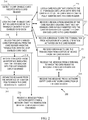
- FIG. 2 is a diagram of a method 200 for card reader locking and unlocking, according to an example embodiment.
- the software module(s) that implements the method 200 is referred to as a "card controller.”
- the card controller is implemented as executable instructions programmed and residing within memory and/or a non-transitory computer-readable (processor-readable) storage medium and executed by one or more hardware processors of a hardware computing device.
- the processors of the device that executes the card controller are specifically configured and programmed to process for controlling one or more electromechanical components of a card reader.
- the card controller may or may not have access to one or more networks during its processing. Any such networks can be wired, wireless, or a combination of wired and wireless.
- the device that executes the card controller is the card reader 100.
- the card reader 100 is an independent standalone computing device interfaced to a terminal.
- the card reader 100 is an independent integrated peripheral devices integrated into one of: an SST (such as SST 120) and a POS terminal.
- the device that executes the card controller is a SST (such as SST 120) to which the card reader 100 is integrated.
- the device that executes the card controller is a POS terminal to which the card reader 100 is integrated.
- the card controller detects a chip-enabled card inserted into a card reader. This can be done through a variety of manners through sensors within the card reader to messages from other devices or interfaces to which the card reader is interfaced to (some of which were discussed above with the FIGS. 1A-1B and some discussed below with reference to the FIG. 3 .
- the card controller locks the chip-enabled card in the card reader until a transaction with the chip-enabled card ends.
- the indication that the card needs locked and is fully inserted into the card reader can occur in a variety of manners.
- the card controller locks a card roller that contacts the chip-enabled card upon entry into the card reader once the chip-enabled card is fully inserted into the card reader.
- the card controller receives a reading from one or more sensors of the card reader indicating that the chip-enabled card is fully inserted into the card reader before locking the chip-enabled card in the card reader.
- the card controller receives a message to end the transaction from activation of a cancel operation activated on the card reader (such as the cancel button 102 or through other soft or hard interface buttons as discussed above with the FIG. 1A ).
- a cancel operation activated on the card reader (such as the cancel button 102 or through other soft or hard interface buttons as discussed above with the FIG. 1A ).
- the card controller receives a message to end the transaction from a different device from the card reader.
- the card controller receives the message from a terminal to which the card reader is integrated into as a peripheral device.
- the card controller receives the message from a network entity over a network connection of the card reader.
- the network entity is the transaction authorizing entity (such as an EMV process or a bank implemented the EMV process).
- the card controller unlocks the chip-enabled card for removal from the card reader when the transaction with the chip-enabled card ends.
- the card controller receives a message from an interface indicating that the transaction with the chip-enabled card has ended.
- the card controller obtains the message from the interface of an SST or a POS terminal to which the card reader is integrated or a part of.
- the card controller receives a message from a network entity over a network that the transaction with the chip-enabled card has ended.
- the network entity is an EMV process or a bank implementing the EMV process.
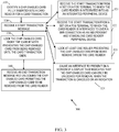
- FIG. 3 is a diagram of another method for card reader locking and unlocking, according to an example embodiment.
- the software module(s) that implements the method 300 is referred to as a "card lock manager.”
- the card lock manager is implemented as executable instructions programmed and residing within memory and/or a non-transitory computer-readable (processor-readable) storage medium and executed by one or more hardware processors of a hardware device.
- the processors of the device that executes the card lock manager are specifically configured and programmed to process the authentication service.
- the card lock manager may or may not have access to one or more networks during its processing. Any such networks can be wired, wireless, or a combination of wired and wireless.
- the device that executes the card lock manager is the card reader 100.
- the card reader 100 is an independent standalone device interfaced to a terminal (SST 120 or POS terminal).
- the card reader 100 is integrated as a peripheral device within the SST 120 or a POS terminal.
- the card lock manager implements the processing discussed above in any of the FIGS. 1A-1B and 2 .
- the card lock manager identifies a chip-enabled card fully inserted into a card reader for a card transaction.
- the card lock manager receives a start transaction message. This can occur in a variety of manners depending upon how the card reader is configured.
- the card lock manager receives the start transaction from an SST or a POS terminal to which the card reader is integrated into as an integrated peripheral device.
- the card lock manager receives the start transaction from an SST or a POS terminal to which the card reader is interfaced to over a bus connection as an independent and standalone card reader peripheral device.
- the card lock manager locks at least one roller preventing the chip-enabled card from being removed from the card reader.
- the card lock manager causes an interface to present on a screen of a display an indication that the chip-enabled card can only be unlocked from removal when the transaction is canceled or an indication is received that the transaction completed or was denied.
- the card lock manager locks the chip-enabled card inside the card reader preventing the chip-enabled card from being removed until the card transaction ends.
- the card lock manager receives an end transaction message and unlocks the chip-enabled card permitting the chip-enabled card to be removed from the card reader.
- FIG. 4 is a diagram of a card reader 400, according to an example embodiment, according to an example embodiment.
- the card reader 400 includes a variety of hardware components and software components.
- the software components of the card reader 400 are programmed and reside within memory and/or a non-transitory computer-readable medium and execute on one or more hardware processors of the card reader 400.
- the card reader 400 communicates one or more networks, which can be wired, wireless, or a combination of wired and wireless.
- the card reader 400 implements all, any, or some combination of the processing discussed above with the FIGS. 1A-1B and 2-3 .
- the system 400 includes at least one hardware processor 401 and card lock manager 402.
- the card reader 400 is the card reader 100.
- the card reader 400 is a standalone peripheral device interfaced to the SST 120 or a POS terminal.
- the SST is an ATM.
- the SST is a kiosk.
- the card reader 400 is integrated into as an integrated peripheral device integrated into the SST 120 or a POS terminal.
- the card lock manager 402 is configured to: execute on the hardware processor 401, detect when a chip-enabled card is fully inserted into the card reader 400, and lock the chip-enabled card until an indication is received that a card transaction being performed with the chip-enabled card has ended.
- modules are illustrated as separate modules, but may be implemented as homogenous code, as individual components, some, but not all of these modules may be combined, or the functions may be implemented in software structured in any other convenient manner.
Landscapes
- Physics & Mathematics (AREA)
- General Physics & Mathematics (AREA)
- Engineering & Computer Science (AREA)
- Theoretical Computer Science (AREA)
- Business, Economics & Management (AREA)
- Accounting & Taxation (AREA)
- Finance (AREA)
- Artificial Intelligence (AREA)
- Computer Vision & Pattern Recognition (AREA)
- Cash Registers Or Receiving Machines (AREA)
- Lock And Its Accessories (AREA)
Abstract
Description
- Credit card theft is a major concern worldwide. Typically, a consumer is protected from theft as is the bank that issues a credit card. That is, when illegal use of a credit card is confirmed after an investigation by the bank, the consumer's account is credited for the amount of theft. However, the bank typically debits the account of a retailer that performed the illegal transaction.
- To thwart illegal credit card use, banks have started to roll out dual chip-magnetic strip cards, such cards have been deployed in Europe for several years now and are in the processes of being fully deployed to United State (U.S.) based consumers.
- The magnetic card readers that read chip-enabled cards are problematic to the U.S. consumer and U.S. retailer. Typically, legacy card readers that were supposed to be used for magnetic strip reading have been upgraded to read the embedded chip. The device or host device (Self-Service Terminal (SST)) interfaces were also upgraded to instruct consumers to leave the card in the card reader for the duration of the transaction (until canceled by the consumer, approved and completed, or denied by the bank).
- The embedded chip on the card has to stay in the card reader for the entirety of the transaction because the reader includes a card-specific embedded key (which may be randomly updated during a transaction with a new key by the bank during the transaction). The key is used to encrypt the transaction on a unique transaction basis. This takes more processing time and therefore the card and its embedded chip have to remain in the card reader for the duration of a given transaction.
- Unfortunately, this is problematic in the U.S. and for the U.S. consumer. The upgraded card readers do not physically lock the card in place during the transaction and the U.S. consumer is condition to insert and remove their cards quickly and often ignore the new interface warnings.
- This is problematic for retailers for a variety of reasons. First, even for a failed transaction the banks charge the retailer a small transaction fee, which for a large retailer can add up to a significant amount of fees (especially given the frequency of failed transactions). Second, during high consumer traffic times, failed transactions delay transaction throughput at both cashier-assisted Point-Of-Sale (POS) terminals and at SSTs. So, the problem has fairly significant ramifications for retailers.
- In various embodiments, methods and a card reader for chip embedded card reader locking are presented.
- According to an embodiment, a method for card reader locking is provided. Specifically, in an embodiment, a chip-enabled card is detected as being inserted into a card reader. Next, the chip-enabled card is locked in the card reader until a transaction with the chip-enabled card ends.
- According to a first aspect of the present invention there is provided a method, comprising: detecting a chip-enabled card inserted into a card reader; and locking the chip-enabled card in the card reader until a transaction with the chip-enabled card ends.
- The method optionally further comprises unlocking the chip-enabled card for removal from the card reader when the transaction with the chip-enabled card ends.
- Unlocking the card optionally further includes receiving a message from an interface indicating that the transaction with the chip-enabled card has ended. The interface may be to a Self-Service Terminal or Point-Of-Sale terminal in which the card reader is integrated.
- Unlocking the card optionally further includes receiving a message from a network entity over a network that the transaction with the chip-enabled card has ended.
- Locking the card optionally further includes locking a card roller that contacts the chip-enabled card upon entry into the card read once the chip-enabled card is fully inserted into the card reader.
- Locking the card optionally further includes receiving a reading from sensors of the card reader indicating that the chip-enabled card is fully inserted into the card reader before locking the chip-enabled card in the card reader.
- Locking the card optionally further includes receiving a message to end the transaction from activation of a cancel operation activated on the card reader.
- Locking the card optionally further includes receiving a message to end the transaction from a different device from the card reader. The message may be received from a terminal in which the card reader is integrated as a peripheral device.
- The step of receiving optionally further includes receiving the message from a network entity over a network connection of the card reader.
- According to a second aspect of the present invention there is provided a card reader, comprising: a hardware processor; an unlock manager configured to i) execute on the hardware processor, ii) detect when a chip-enabled card is fully inserted into the card reader, and iii) lock the chip-enabled card inside the card reader until an indication is received that a card transaction being performed with the chip-enabled card has ended.
- The card reader is optionally a standalone and independent peripheral device that is interfaced to a Self-Service Terminal (SST) or a Point-Of-Sale terminal.
- The SST may be one of: an Automated Teller Machine (ATM) and a kiosk.
- According to a third aspect of the present invention there is provided a method, comprising: identifying a chip-enabled card fully inserted into a card reader for a card transaction; receiving a start transaction message; and locking the chip-enabled card inside the card reader preventing the chip-enabled card from being removed until the card transaction ends.
- The method optionally further comprises receiving an end transaction message and unlocking the chip-enabled card permitting the chip-enabled card to be removed from the card reader.
- The step of receiving an end transaction message optionally further includes receiving the start transaction from a Self-Service Terminal or a Point-Of-Sale terminal to which the card reader is integrated into as an integrated peripheral device.
- The method optionally further includes receiving a start transaction message from a Self-Service Terminal or a Point-Of-Sale terminal to which the card reader is interfaced to over a bus connection as an independent and standalone card reader peripheral device.
- Locking the chip-enabled card optionally further includes locking at least one roller preventing the chip-enabled card from being removed from the card reader.
- Locking the chip-enabled card optionally further includes causing an interface to present on a screen of a display that indicates that the chip-enabled card can only be unlocked for removal when the transaction is canceled or an indication is received that the transaction completed or was denied.
- These and other aspects of the present invention will be apparent from the following specific description, given by way of example, with reference to the accompanying drawings, in which:
-
FIG. 1A is a diagram of a card reader, according to an example embodiment; -
FIG. 1B is a diagram a Self-Service Terminal (SST) having an integrated card reader, according to an example embodiment; -
FIG. 2 is a diagram of a method for card reader locking and unlocking, according to an example embodiment; -
FIG. 3 is a diagram of another method for card reader locking and unlocking, according to an example embodiment; and -
FIG. 4 is a diagram of a card reader, according to an example embodiment. -
FIG. 1A is a diagram of acard reader 100, according to an example embodiment. Thecard reader 100 is shown schematically in greatly simplified form, with only those components relevant to understanding of one or more embodiments (represented herein) being illustrated. The various components are illustrated and the arrangement of the components is presented for purposes of illustration only. It is to be noted that other arrangements with more or less components are possible without departing from the card reader locking presented herein and below. - Moreover, various components are illustrated as one or more software modules, which residing in non-transitory storage and/or hardware memory as executable instructions that when executed by one or more hardware processors perform the processing discussed herein and below.
- The techniques, methods, and systems presented herein and below for card reader locking can be implemented in all, or some combination of the components shown in different hardware computing devices having one or more hardware processors.
- The
card reader 100 includes adisplay 101, one or more interface buttons (102 and 103), and at least oneinternal roller mechanism 104. Thecard reader 100 processes chip-enabled credit/debit cards 110 having an embeddedchip 111, and amagnetic strip 112. - It is noted that the layout of the
card reader 100 can be in a variety of different permutations. For example, thedisplay 101 can be a touchscreen, theinterface buttons card reader 100 and situated adjacent to thedisplay 101. It may also be that thecard reader 100 is integrated into a Self-Service Terminal (SST) and uses the touchscreen interface of the SST and/or the keyboard of the SST. It may be also that the card reader is integrated into a Point-Of-Sale (POS) terminal. - Moreover, there can be more than two
hard interface buttons standalone card reader 100. Twobuttons confirm amount button 102 and acancel button 103; but it is noted that this can done in a variety of manners and thebuttons card reader 100 and are present in a touchscreen of the display 101 (or any of the other possible configurations for the standalone card reader 100). - During a transaction, a customer inserts his/her
card 110 into thecard reader 100 in an orientation dictated by instructions posted on or near thecard reader 100 or by instructions illustrated in an interface presentation presented on thedisplay 100. Therefore, the illustration on the orientation of thecard 110 inserted into thecard reader 100 can vary depending on the configuration of thecard reader 100 and the exact orientation in theFIG. 1A is one or many possible orientations. - The
roller mechanism 104 includes a roller and is illustrated in a manner for visibility and comprehension as it is apparent that theroller mechanism 104 is not visible to the consumer and is internal to thecard reader 104. - The
roller mechanism 104 is also interfaced to one or more electromechanical components controlled by electronic circuitry interfaced to a motherboard having at least one hardware processor that receives sensor and signal readings from the electromechanical components and permit the hardware processor responsive to the readings to control and operate theroller mechanism 104. - During operation of the
card reader 100, when a consumer inserts his/hercard 110 into thecard reader 100 in a designated and proper orientation, sensors indicate to the hardware processor when thecard 110 is fully and properly inserted into thecard reader 100 for proper reading and processing during a transaction. At this point, the hardware processor locks the roller of theroller mechanism 104, which prevents thecard 110 from being manually removed by the consumer until the transaction ends (canceled by the customer through cancelbutton 103, completed as indicated by the terminal to which thecard reader 100 is interfaced (SST or POS terminal), or denied as a form of payment for a transaction by the terminal. Once the transaction ends, the hardware processor receives that indication from either the terminal, interface, or thereader 100 and the hard processor causes theroller mechanism 104 to unlock permitting the consumer to freely remove thecard 110. - In an embodiment, the roller of the
roller mechanism 104 is a slip resistant roller. - In an embodiment, the motherboard and hardware processor reside within the
card reader 100. - In an embodiment, the motherboard and hardware processor reside external to the
card reader 100 and connected to an electronic circuit board, where the motherboard controls other devices. In this embodiment, thecard reader 100 is integrated into another device, such as an SST or POS terminal. - The
FIG. 1A also includes some descriptive material relevant to a card transaction, such as an indication that thecard reader 100 is EMV enabled. EMV stands for Europay MasterCard® and Visa® and is a transaction processing mechanism that uses card embedded chips to unique encrypt each transaction and validate the transaction. - In an embodiment, the
card reader 100 is integrated into an SST. In an embodiment, the SST is an Automated Teller Machine (ATM). In an embodiment, the SST is a kiosk. - In an embodiment, the
card reader 100 is integrated into a POS terminal. -
FIG. 1B is a diagram aSST 120 having anintegrated card reader 100, according to an example embodiment. -
FIG. 1B is shown to illustrate that thecard reader 100 can be integrated into the SST 120 (non-standalone card reader 100 embodiment). - The
card reader 100 detects an insertedcard 110 having an embeddedchip 111 fully inserted into thecard reader 100 and locks theroller mechanism 104 until the transaction ends (as defined above) at which point thecard reader 100 unlocks theroller mechanism 104 for thecard 110 to be removed from thecard reader 100. - In an embodiment, the software (executable instructions) and the hardware processor that receive the readings for the hardware processor to make a determination as to when to lock the
roller mechanism 104 and when to unlock the roller mechanism are contained within theintegrated card reader 100 as an independent peripheral device of theSST 120. - In an embodiment, the software (executable instructions) and the hardware processor that receive the readings for the hardware processor to make the determination as to when to lock the
roller mechanism 104 and when to unlock theroller mechanism 104 are external to thecard reader 100 and connected to an electronic circuit board within the SST. - These and other embodiments are now discussed with reference to the
FIGS. 2-4 . -
FIG. 2 is a diagram of amethod 200 for card reader locking and unlocking, according to an example embodiment. The software module(s) that implements themethod 200 is referred to as a "card controller." The card controller is implemented as executable instructions programmed and residing within memory and/or a non-transitory computer-readable (processor-readable) storage medium and executed by one or more hardware processors of a hardware computing device. The processors of the device that executes the card controller are specifically configured and programmed to process for controlling one or more electromechanical components of a card reader. The card controller may or may not have access to one or more networks during its processing. Any such networks can be wired, wireless, or a combination of wired and wireless. - In an embodiment, the device that executes the card controller is the
card reader 100. In an embodiment of this embodiment, thecard reader 100 is an independent standalone computing device interfaced to a terminal. In another embodiment of this embodiment, thecard reader 100 is an independent integrated peripheral devices integrated into one of: an SST (such as SST 120) and a POS terminal. - In an embodiment, the device that executes the card controller is a SST (such as SST 120) to which the
card reader 100 is integrated. - In an embodiment, the device that executes the card controller is a POS terminal to which the
card reader 100 is integrated. - At 210, the card controller detects a chip-enabled card inserted into a card reader. This can be done through a variety of manners through sensors within the card reader to messages from other devices or interfaces to which the card reader is interfaced to (some of which were discussed above with the
FIGS. 1A-1B and some discussed below with reference to theFIG. 3 . - At 220, the card controller locks the chip-enabled card in the card reader until a transaction with the chip-enabled card ends. The indication that the card needs locked and is fully inserted into the card reader can occur in a variety of manners.
- For example, at 221, the card controller locks a card roller that contacts the chip-enabled card upon entry into the card reader once the chip-enabled card is fully inserted into the card reader.
- According to another case, at 222, the card controller receives a reading from one or more sensors of the card reader indicating that the chip-enabled card is fully inserted into the card reader before locking the chip-enabled card in the card reader.
- In an embodiment, at 223, the card controller receives a message to end the transaction from activation of a cancel operation activated on the card reader (such as the cancel
button 102 or through other soft or hard interface buttons as discussed above with theFIG. 1A ). - In an embodiment, at 224, the card controller receives a message to end the transaction from a different device from the card reader.
- For example, and in an embodiment of 224, at 225, the card controller receives the message from a terminal to which the card reader is integrated into as a peripheral device.
- In an embodiment of 225 and at 226, the card controller receives the message from a network entity over a network connection of the card reader. In an embodiment, the network entity is the transaction authorizing entity (such as an EMV process or a bank implemented the EMV process).
- According to an embodiment, at 230, the card controller unlocks the chip-enabled card for removal from the card reader when the transaction with the chip-enabled card ends.
- In an embodiment of 230 and at 240, the card controller receives a message from an interface indicating that the transaction with the chip-enabled card has ended.
- In an embodiment of 240 and at 241, the card controller obtains the message from the interface of an SST or a POS terminal to which the card reader is integrated or a part of.
- In an embodiment of 230 and at 250, the card controller receives a message from a network entity over a network that the transaction with the chip-enabled card has ended. In an embodiment, the network entity is an EMV process or a bank implementing the EMV process.
-
FIG. 3 is a diagram of another method for card reader locking and unlocking, according to an example embodiment. The software module(s) that implements themethod 300 is referred to as a "card lock manager." The card lock manager is implemented as executable instructions programmed and residing within memory and/or a non-transitory computer-readable (processor-readable) storage medium and executed by one or more hardware processors of a hardware device. The processors of the device that executes the card lock manager are specifically configured and programmed to process the authentication service. The card lock manager may or may not have access to one or more networks during its processing. Any such networks can be wired, wireless, or a combination of wired and wireless. - In an embodiment, the device that executes the card lock manager is the
card reader 100. In an embodiment of this embodiment, thecard reader 100 is an independent standalone device interfaced to a terminal (SST 120 or POS terminal). In another embodiment of this embodiment, thecard reader 100 is integrated as a peripheral device within theSST 120 or a POS terminal. - In an embodiment, the card lock manager implements the processing discussed above in any of the
FIGS. 1A-1B and2 . - At 310, the card lock manager identifies a chip-enabled card fully inserted into a card reader for a card transaction.
- At 320, the card lock manager receives a start transaction message. This can occur in a variety of manners depending upon how the card reader is configured.
- For example, at 321, the card lock manager receives the start transaction from an SST or a POS terminal to which the card reader is integrated into as an integrated peripheral device.
- In another case, at 322, the card lock manager receives the start transaction from an SST or a POS terminal to which the card reader is interfaced to over a bus connection as an independent and standalone card reader peripheral device.
- In an embodiment, the card lock manager locks at least one roller preventing the chip-enabled card from being removed from the card reader.
- In an embodiment, at 324, the card lock manager causes an interface to present on a screen of a display an indication that the chip-enabled card can only be unlocked from removal when the transaction is canceled or an indication is received that the transaction completed or was denied.
- At 330, the card lock manager locks the chip-enabled card inside the card reader preventing the chip-enabled card from being removed until the card transaction ends.
- According to an embodiment, at 340, the card lock manager receives an end transaction message and unlocks the chip-enabled card permitting the chip-enabled card to be removed from the card reader.
-
FIG. 4 is a diagram of acard reader 400, according to an example embodiment, according to an example embodiment. Thecard reader 400 includes a variety of hardware components and software components. The software components of thecard reader 400 are programmed and reside within memory and/or a non-transitory computer-readable medium and execute on one or more hardware processors of thecard reader 400. Thecard reader 400 communicates one or more networks, which can be wired, wireless, or a combination of wired and wireless. - In an embodiment, the
card reader 400 implements all, any, or some combination of the processing discussed above with theFIGS. 1A-1B and2-3 . - The
system 400 includes at least onehardware processor 401 andcard lock manager 402. - In an embodiment, the
card reader 400 is thecard reader 100. - In an embodiment, the
card reader 400 is a standalone peripheral device interfaced to theSST 120 or a POS terminal. In an embodiment, the SST is an ATM. In an embodiment, the SST is a kiosk. - In an embodiment, the
card reader 400 is integrated into as an integrated peripheral device integrated into theSST 120 or a POS terminal. - The
card lock manager 402 is configured to: execute on thehardware processor 401, detect when a chip-enabled card is fully inserted into thecard reader 400, and lock the chip-enabled card until an indication is received that a card transaction being performed with the chip-enabled card has ended. - It should be appreciated that where software is described in a particular form (such as a component or module) this is merely to aid understanding and is not intended to limit how software that implements those functions may be architected or structured. For example, modules are illustrated as separate modules, but may be implemented as homogenous code, as individual components, some, but not all of these modules may be combined, or the functions may be implemented in software structured in any other convenient manner.
- Furthermore, although the software modules are illustrated as executing on one piece of hardware, the software may be distributed over multiple processors or in any other convenient manner.
- The above description is illustrative, and not restrictive. Many other embodiments will be apparent to those of skill in the art upon reviewing the above description. The scope of embodiments should therefore be determined with reference to the appended claims, along with the full scope of equivalents to which such claims are entitled.
- In the foregoing description of the embodiments, various features are grouped together in a single embodiment for the purpose of streamlining the disclosure. This method of disclosure is not to be interpreted as reflecting that the claimed embodiments have more features than are expressly recited in each claim; rather, as the following claims reflect, inventive subject matter lies in less than all features of a single disclosed embodiment.
Claims (14)
- A method (200 or 300) comprising:detecting a chip-enabled card (110) inserted into a card reader (100 or 400) (step 210 or 310); andlocking the chip-enabled card (110) in the card reader (100 or 400) until a transaction with the chip-enabled card (110) ends (step 220 or 330).
- The method of claim 1 further comprising unlocking the chip-enabled card (110) for removal from the card reader (100 or 400) when the transaction with the chip-enabled card (110) ends (step 230 or 340).
- The method of claim 2, wherein unlocking further includes receiving a message from an interface indicating that the transaction with the chip-enabled card has ended (step 240).
- The method of claim 3, wherein receiving further obtaining the message from the interface of a self-service terminal (120) or point-of-sale terminal in which the card reader (100 or 400) is integrated.
- The method of claim 2, wherein unlocking further includes receiving a message from a network entity over a network that the transaction with the chip-enabled card has ended (step 226).
- The method of any preceding claim, wherein locking further includes locking a card roller (104) that contacts the chip-enabled card (110) upon entry into the card reader (100 or 400) once the chip-enabled card (110) is fully inserted into the card reader (100 or 400).
- The method of any preceding claim, wherein locking further includes receiving a reading from sensors of the card reader (100 or 400) indicating that the chip-enabled card (110) is fully inserted into the card reader (100 or 400) before locking the chip-enabled card in the card reader (100 or 400) (step 222).
- The method of any preceding claim, wherein locking further includes receiving a message to end the transaction from activation of a cancel operation activated on the card reader (100 or 400) (step 223).
- The method of any preceding claim, wherein locking further includes receiving a message to end the transaction from a different device from the card reader (100 or 400) (step 224).
- The method of claim 9, wherein receiving further includes receiving the message from a terminal in which the card reader (100 or 400) is integrated as a peripheral device (step 225).
- The method of claim 9, wherein receiving further includes receiving the message from a network entity over a network connection of the card reader (100 or 400) (step 226).
- A card reader (100 or 400) comprising:a hardware processor (401);an unlock manager (402) configured to (i) execute on the hardware processor (401), (ii) detect when a chip-enabled card (110) is fully inserted into the card reader (100 or 400), and (iii) lock the chip-enabled card (110) inside the card reader (100 or 400) until an indication is received that a card transaction being performed with the chip-enabled card (110) has ended.
- The card reader of claim 12, wherein the card reader (100 or 400) is a peripheral device interfaced to a self-service terminal (120) or a point-of-sale terminal.
- The card reader of claim 13, wherein the self-service terminal (120) is an Automated Teller Machine or a kiosk.
Applications Claiming Priority (1)
| Application Number | Priority Date | Filing Date | Title |
|---|---|---|---|
| US15/054,954 US9652640B1 (en) | 2016-02-26 | 2016-02-26 | Card locking |
Publications (1)
| Publication Number | Publication Date |
|---|---|
| EP3211610A1 true EP3211610A1 (en) | 2017-08-30 |
Family
ID=58017993
Family Applications (1)
| Application Number | Title | Priority Date | Filing Date |
|---|---|---|---|
| EP17155801.8A Pending EP3211610A1 (en) | 2016-02-26 | 2017-02-13 | Card locking |
Country Status (3)
| Country | Link |
|---|---|
| US (1) | US9652640B1 (en) |
| EP (1) | EP3211610A1 (en) |
| CN (1) | CN107134077A (en) |
Families Citing this family (2)
| Publication number | Priority date | Publication date | Assignee | Title |
|---|---|---|---|---|
| US10628829B1 (en) * | 2019-05-29 | 2020-04-21 | Capital One Services, Llc | Utilizing a machine learning model to perform actions based on selection of a single selection abort transaction mechanism |
| US12236420B2 (en) * | 2021-06-29 | 2025-02-25 | Ncr Corporation | Card reader verification |
Citations (6)
| Publication number | Priority date | Publication date | Assignee | Title |
|---|---|---|---|---|
| EP1035495A2 (en) * | 1999-03-08 | 2000-09-13 | Matsushita Electric Industrial Co., Ltd. | IC card reader |
| US20050023348A1 (en) * | 2003-03-07 | 2005-02-03 | Lucas Bennie E. | Integrated circuit and magnetic stripe reader |
| US20050150954A1 (en) * | 2003-12-17 | 2005-07-14 | Sankyo Seiki Mfg. Co., Ltd. | Card reader |
| EP1630724A1 (en) * | 2003-05-23 | 2006-03-01 | Omron Corporation | Card processing device |
| US20060086793A1 (en) * | 2004-10-25 | 2006-04-27 | Sankyo Seiki Mfg. Co., Ltd. | Card reader |
| WO2015087866A1 (en) * | 2013-12-10 | 2015-06-18 | 日本電産サンキョー株式会社 | Card reader |
Family Cites Families (4)
| Publication number | Priority date | Publication date | Assignee | Title |
|---|---|---|---|---|
| US6254005B1 (en) * | 1999-06-03 | 2001-07-03 | Qi Technologies Corp. | Card reader with card capture clamp |
| NO315727B1 (en) * | 2002-02-22 | 2003-10-13 | Handcash As | Debit card and related procedure |
| US7160413B2 (en) * | 2004-01-09 | 2007-01-09 | Mipox International Corporation | Layered support and method for laminating CMP pads |
| CN103456092B (en) * | 2013-09-16 | 2016-01-20 | 广州广电运通金融电子股份有限公司 | Card reader transaction card method, device |
-
2016
- 2016-02-26 US US15/054,954 patent/US9652640B1/en active Active
-
2017
- 2017-02-13 EP EP17155801.8A patent/EP3211610A1/en active Pending
- 2017-02-21 CN CN201710092440.8A patent/CN107134077A/en active Pending
Patent Citations (6)
| Publication number | Priority date | Publication date | Assignee | Title |
|---|---|---|---|---|
| EP1035495A2 (en) * | 1999-03-08 | 2000-09-13 | Matsushita Electric Industrial Co., Ltd. | IC card reader |
| US20050023348A1 (en) * | 2003-03-07 | 2005-02-03 | Lucas Bennie E. | Integrated circuit and magnetic stripe reader |
| EP1630724A1 (en) * | 2003-05-23 | 2006-03-01 | Omron Corporation | Card processing device |
| US20050150954A1 (en) * | 2003-12-17 | 2005-07-14 | Sankyo Seiki Mfg. Co., Ltd. | Card reader |
| US20060086793A1 (en) * | 2004-10-25 | 2006-04-27 | Sankyo Seiki Mfg. Co., Ltd. | Card reader |
| WO2015087866A1 (en) * | 2013-12-10 | 2015-06-18 | 日本電産サンキョー株式会社 | Card reader |
Also Published As
| Publication number | Publication date |
|---|---|
| US9652640B1 (en) | 2017-05-16 |
| CN107134077A (en) | 2017-09-05 |
Similar Documents
| Publication | Publication Date | Title |
|---|---|---|
| US11954687B2 (en) | Fraud detection in self-service terminal | |
| CA3044726C (en) | Providing an augmented reality overlay to secure input data | |
| AU2021254551A1 (en) | Transaction authorisation | |
| EP3667552B1 (en) | Radio tag reading device and method | |
| US12288199B2 (en) | Casino cash system, apparatus and method utilizing integrated circuit cards | |
| TR201807794T4 (en) | The method of card processing in the card reader, the device and its self-service hardware. | |
| US10096026B1 (en) | Multi-factor automated teller machine (ATM) personal identification number (PIN) | |
| US9652640B1 (en) | Card locking | |
| CN100504939C (en) | Automatic cash transaction device | |
| US12499446B2 (en) | Card skimming detection | |
| US11373487B2 (en) | Automatic teller machine, terminal device, and medium reading method | |
| CN104303214A (en) | Automatic transaction device and automatic transaction method | |
| CN1825364B (en) | Biometrics authentication system | |
| JP2019139328A5 (en) | ||
| JP2016157261A (en) | Lost thing prevention system, lost article prevention method and customer use type terminal. | |
| WO2016194561A1 (en) | Transaction device | |
| JP2007087316A (en) | Automatic transaction device and automatic transaction system | |
| EP4332828B1 (en) | Skimming and magnetic read prevention | |
| JP6752161B2 (en) | ATMs, card readers and methods | |
| JP2015111363A (en) | Transaction device and transaction method | |
| JP6585135B2 (en) | Automatic transaction equipment | |
| JP2010129066A (en) | Automatic teller machine using biometric authentication | |
| JP6634846B2 (en) | Automatic transaction equipment and transaction system | |
| KR20070063706A (en) | Financial automation equipment operated in abnormal mode using the authorization code. And its operation method | |
| KR20070063714A (en) | Financial teller machine with previous button and its operation method |
Legal Events
| Date | Code | Title | Description |
|---|---|---|---|
| PUAI | Public reference made under article 153(3) epc to a published international application that has entered the european phase |
Free format text: ORIGINAL CODE: 0009012 |
|
| STAA | Information on the status of an ep patent application or granted ep patent |
Free format text: STATUS: THE APPLICATION HAS BEEN PUBLISHED |
|
| AK | Designated contracting states |
Kind code of ref document: A1 Designated state(s): AL AT BE BG CH CY CZ DE DK EE ES FI FR GB GR HR HU IE IS IT LI LT LU LV MC MK MT NL NO PL PT RO RS SE SI SK SM TR |
|
| AX | Request for extension of the european patent |
Extension state: BA ME |
|
| STAA | Information on the status of an ep patent application or granted ep patent |
Free format text: STATUS: REQUEST FOR EXAMINATION WAS MADE |
|
| 17P | Request for examination filed |
Effective date: 20180228 |
|
| RBV | Designated contracting states (corrected) |
Designated state(s): AL AT BE BG CH CY CZ DE DK EE ES FI FR GB GR HR HU IE IS IT LI LT LU LV MC MK MT NL NO PL PT RO RS SE SI SK SM TR |
|
| RAP1 | Party data changed (applicant data changed or rights of an application transferred) |
Owner name: NCR CORPORATION |
|
| STAA | Information on the status of an ep patent application or granted ep patent |
Free format text: STATUS: EXAMINATION IS IN PROGRESS |
|
| 17Q | First examination report despatched |
Effective date: 20191210 |
|
| P01 | Opt-out of the competence of the unified patent court (upc) registered |
Effective date: 20230505 |
|
| RAP3 | Party data changed (applicant data changed or rights of an application transferred) |
Owner name: NCR VOYIX CORPORATION |