EP3210846A1 - Device for temporarily fixing a balise in a platform formed of two rails - Google Patents
Device for temporarily fixing a balise in a platform formed of two rails Download PDFInfo
- Publication number
- EP3210846A1 EP3210846A1 EP16157529.5A EP16157529A EP3210846A1 EP 3210846 A1 EP3210846 A1 EP 3210846A1 EP 16157529 A EP16157529 A EP 16157529A EP 3210846 A1 EP3210846 A1 EP 3210846A1
- Authority
- EP
- European Patent Office
- Prior art keywords
- rail
- balise
- rails
- track
- floor rails
- Prior art date
- Legal status (The legal status is an assumption and is not a legal conclusion. Google has not performed a legal analysis and makes no representation as to the accuracy of the status listed.)
- Ceased
Links
- 239000002184 metal Substances 0.000 claims abstract description 8
- 229910000831 Steel Inorganic materials 0.000 claims abstract description 3
- 239000010959 steel Substances 0.000 claims abstract description 3
- 238000010276 construction Methods 0.000 description 3
- 238000012544 monitoring process Methods 0.000 description 3
- 241001295925 Gegenes Species 0.000 description 2
- 230000005540 biological transmission Effects 0.000 description 2
- 239000004020 conductor Substances 0.000 description 2
- 238000009434 installation Methods 0.000 description 2
- 238000000034 method Methods 0.000 description 2
- 230000011664 signaling Effects 0.000 description 2
- 238000001514 detection method Methods 0.000 description 1
- 230000000694 effects Effects 0.000 description 1
- 238000009413 insulation Methods 0.000 description 1
- 238000010409 ironing Methods 0.000 description 1
- 238000002955 isolation Methods 0.000 description 1
- 210000003739 neck Anatomy 0.000 description 1
- 230000001105 regulatory effect Effects 0.000 description 1
- 238000005096 rolling process Methods 0.000 description 1
Images

Classifications
-
- B—PERFORMING OPERATIONS; TRANSPORTING
- B61—RAILWAYS
- B61L—GUIDING RAILWAY TRAFFIC; ENSURING THE SAFETY OF RAILWAY TRAFFIC
- B61L3/00—Devices along the route for controlling devices on the vehicle or train, e.g. to release brake or to operate a warning signal
- B61L3/02—Devices along the route for controlling devices on the vehicle or train, e.g. to release brake or to operate a warning signal at selected places along the route, e.g. intermittent control simultaneous mechanical and electrical control
- B61L3/08—Devices along the route for controlling devices on the vehicle or train, e.g. to release brake or to operate a warning signal at selected places along the route, e.g. intermittent control simultaneous mechanical and electrical control controlling electrically
- B61L3/12—Devices along the route for controlling devices on the vehicle or train, e.g. to release brake or to operate a warning signal at selected places along the route, e.g. intermittent control simultaneous mechanical and electrical control controlling electrically using magnetic or electrostatic induction; using radio waves
- B61L3/126—Constructional details
-
- E—FIXED CONSTRUCTIONS
- E01—CONSTRUCTION OF ROADS, RAILWAYS, OR BRIDGES
- E01B—PERMANENT WAY; PERMANENT-WAY TOOLS; MACHINES FOR MAKING RAILWAYS OF ALL KINDS
- E01B29/00—Laying, rebuilding, or taking-up tracks; Tools or machines therefor
- E01B29/32—Installing or removing track components, not covered by the preceding groups, e.g. sole-plates, rail anchors
Definitions
- the present invention relates to a device for temporarily placing a balise in a track formed by two gang rails.
- decentralized functional units are used in rail transport networks, where they are used to control and monitor vehicle-influencing and / or vehicle-monitoring units in terms of functionality and to record process data and back to a central control and / or monitoring center , such as a control center or a signal box, to report.
- a central control and / or monitoring center such as a control center or a signal box
- As Switzerlandbeeinu units that give instructions to the driver or even make direct intervention in the vehicle control or directly set a safe track for example, signals, points, balises, line conductors, track magnets and the like, as well as sensors for detecting process variables of the moving train, such as power consumption, speed and the like.
- train and track section monitoring units can also balise and line conductors, but also axle and track circuits and other train detection systems are called.
- the train control systems are highly regulated and often proprietary.
- the new Europe-wide European Train Control System uses line and point transmission units, such as the above-mentioned balises and loop cables, which are used on straight and twisty sections near signaling points (main and pre-signals) ) be used.
- ECS European Train Control System
- new euro balises must be installed in large numbers, which can usually be carried out only with a rolling wheel. Therefore, in particular for the time of construction sites there is a great need for the at least temporary arrangement of balises, in particular the so-called Euro-balises.
- balises were the same as permanently installed balises mounted by means of tie rods or with a bore on the thresholds, which is time consuming and causes considerable costs. Solutions have already been pre-applied with straps or chains, but with these means an assembly with repeatable clamping forces can not be achieved. However, this is absolutely necessary in order to guarantee a safe installation even at higher speeds (for example at 160 km / h and more).
- the present invention is therefore an object of the invention to provide a device for temporary placement of a balise in a track formed from two floor rails, which allows easy installation and arrangement in the track and also meets the strength requirements at high speeds.
- the object is achieved according to the invention by two embodiments of the device in question.
- the clamping device clamping the mounting plate with the two floor rails of the track.
- the rail hooks or the push rods made of metal can be prevented that the balise can not be firmly anchored firmly between the two floor rails.
- the clamping device allows the exact adjustment of a desired Verspannmoments.
- the fastening element can be integrated in the tensioning device or in the push rod, whereby the number of components to be used can be reduced.
- the tensioning device can be designed spring-loaded. This embodiment thus contributes to achieving repeatable clamping forces.
- the clamping device itself can be configured for example as a tensioning cross or locking element. In principle, however, it is advantageous for granting the assurance of the tension when the tensioning device is designed to be lockable in a selected tensioning position. This locking can be achieved for example by the introduction of a bolt or a Federsplints in the clamping device, so that accidental release of the tension can be safely avoided.
- the locked clamping device can be locked in this position.
- This backup can be achieved, for example, relatively simply by attaching a U-lock, which connects the bolt or the Federsplint with the clamping device.
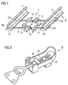
- FIG. 1 shows a schematic representation of a device 2 for temporary attachment of a Beautyse not shown here in a track formed from two rails 4, 6 track 8.
- the device 2 comprises a mounting plate 10, which has holes 12 for mounting the balise.
- the mounting plate 10 is integrated here in a clamping device 14.
- the tensioning device 14 is designed cross-shaped, wherein the two arms of the cross-shaped tensioning device 14 are rotatably mounted about a pivot point 16.
- the tensioning device 14 also has a spring-loaded clamping closure 18, with which the two arms can be tightened relative to each other.
- As an abutment of the tensioning device 14 are two first rail hooks 20a, 20b, which are feasible under a rail foot 22 and are mounted on the outside of the rail foot 22.
- first and second rail hooks 20a, 20b, 24a, 24b are as in FIG FIG. 1 shown mounted on their respective ends remote from the respective rail foot, 22, 26 in each case one arm of the cross-shaped clamping device.
- the tension lock 18 comprises a spring, by means of which a defined tension force can be generated. To compensate for tolerances in the distance between the rail foot outer sides, the tension lock 18 may also include a clamping bracket, which can be adjusted by a screw lengths (see. FIG. 2 ).
- the tension lock further comprises a detent not shown here in detail, with which a safety-relevant independent release can be prevented.
- the tension lock 18 may also include a possibility for closing, so that an unauthorized removal of the device 2 can be at least significantly more difficult.
- the tension lock 18 may also include a possibility for closing, so that an unauthorized removal of the device 2 can be at least significantly more difficult.
- the Figure 3 now schematically shows a second device 34 for temporary attachment of a balise in a track bed between the two floor rails 4, 6.
- the attachment of the balise takes place here on a length-adjustable two-part bracket 36 (with bracket member 36a and bracket member 36b), which with a spread clamping device 18 'against the inner sides of the rail feet 22, 26 is spread.
- the two parts of the bracket 36a, 36b may be made of metal or plastic.
- To secure the insulation of the two floor rails 4, 6 against each other could also be a bracket part, for example, the bracket part 36a, made of metal and the other bracket part, in this example, the bracket part 36b, made of plastic. Analog could also be found in the FIG.
- the end engaging with the rail feet 22, 26 could end with an attached piece of metal.
- the bracket portion 36a is hollow, so that the other bracket portion 36b telescoped into the bracket portion 36a and pulled out (spread) can be.
- To mount the bracket 36 is hardly ever to remove gravel, which of course has an advantageous effect on the assembly.
- the bracket part 36a also has again the mounting holes 12 (as fasteners) for mounting the balise on.
- the two bracket parts 36a, 36b are spread in the installed between the stock rails 4, 6 state by means of a tension bracket against each other.
- a spring in the clamping bracket creates a defined and repeatable clamping force.
- an adjustable in length ironing part can be used.
- the tensioning device 18 ' may also, like the tensioning device 18, comprise a detent which prevents an independent release of the tensioning device 18'.
- a closure may be provided which at least greatly impedes unauthorized removal of the device 34.
- the assembly of the device 34 can also be done on a threshold or be provided between the thresholds in a threshold compartment.
- bracket 36 can be performed with a corresponding design of the ends of the bracket parts 36a, 36b also below the lower edge of a temporarily for construction purposes in the track bed rail.
- the two bracket parts 36a, 36b could also attack on the inside of the rail necks 38, 40, but this has not been specifically shown here.
- FIG. 4 now shows a schematic representation of a further variant of a device 41 for temporary attachment of a balise.
- modified rail hooks 20a 'and 24a' are again performed under the two rail feet 22, 26 and mounted on the outside of the rail feet 22, 26.
- the rail hooks 20a 'and 24a' are held in guides 42 of a tensioning device 44 and, in the assembled state, are tensioned at their ends 46, 48 in the direction of the arrow by means of the tensioning device 44 acting here in a spreading manner.
- this embodiment represents, so to speak, a combination of the principles of action of the devices 2 (rail hooks on the outside of the rail foot) and 34 (expanding tensioning device). All other statements made above on the lockability and closeability apply analogously to this embodiment.
Landscapes
- Engineering & Computer Science (AREA)
- Architecture (AREA)
- Civil Engineering (AREA)
- Structural Engineering (AREA)
- Mechanical Engineering (AREA)
- Train Traffic Observation, Control, And Security (AREA)
Abstract
Die erste Ausführungsform sieht eine Vorrichtung zum temporären Anordnen einer Balise in einem aus zwei Stockschienen gebildeten Gleis vor, welche die folgenden Komponenten umfassend: a) ein Befestigungselement, auf der die Balise montierbar ist; b) mindestens einen ersten Schienenhaken, der unter einem Schienenfuss durchführbar und mit diesem Schienenfuss einer der beiden Stockschienen verspannbar ist; c) mindestens einen zweiten Schienenhaken, der unter einem Schienenfuss durchführbar und mit diesem Schienenfuss der anderen der beiden Stockschienen verspannbar ist; d) eine das Befestigungselement beherbergende und zwischen den beiden Stockschienen angeordnete Spannvorrichtung, an der der mindestens eine erste Schienenhaken und der mindestens eine zweite Schienenhaken direkt oder unter Vermittlung eines Zwischenstücks, insbesondere eines Metallbügels oder ein Stahlseils, indirekt angreift. Eine zweite zur ersten Ausführungsform alternative Ausführungsform sieht eine Vorrichtung zum temporären Anordnen einer Balise in einem aus zwei Stockschienen gebildeten Gleis vor, welche die folgenden Komponenten umfassend: a) ein Befestigungselement, auf der die Balise montierbar ist; b) mindestens eine erste Schubstange, die gleisinnenseitig gegen einem Schienenfuss einer der beiden Stockschienen spannbar ist; c) mindestens eine zweiten Schubstange, die gleisinnenseitig gegen einen Schienenfuss der anderen der beiden Stockschienen spannbar ist; d) eine Spannvorrichtung, in der die mindestens eine erste Schubstange und die mindestens eine zweite Schubstange direkt oder unter Vermittlung eines Zwischenstücks relativ gegeneinander verschiebbar sind. Auf diese Weise ist es möglich durch die mittels der Spannvorrichtung erzielbare Verspannung der Befestigungsplatte mit den beiden Stockschienen des Gleises eine temporäre Befestigung mit wiederholbaren Spannkräften erzielen zu können. Fig. 1The first embodiment provides an apparatus for temporarily placing a balise in a track formed by two gang rails comprising the following components: a) a fastener on which the balise is mountable; b) at least one first rail hook, which can be carried out under a rail foot and braced with this rail foot of one of the two floor rails; c) at least one second rail hook, which can be carried out under a rail foot and with this rail foot of the other of the two floor rails braced; d) a the fastening element accommodating and arranged between the two floor rails tensioning device on which the at least one first rail hook and the at least one second rail hook directly or indirectly through the intermediary of an intermediate piece, in particular a metal strap or a steel cable. A second alternative embodiment to the first embodiment provides an apparatus for temporarily placing a balise in a track formed by two catenary rails, comprising the following components: a) a fastener on which the balise is mountable; b) at least one first push rod, which is tensioned on the track inside against a rail foot of one of the two floor rails; c) at least one second push rod which is tensioned on the inside of the track against a rail foot of the other of the two floor rails; d) a tensioning device, in which the at least one first push rod and the at least one second push rod are displaceable relative to each other directly or by means of an intermediate piece. In this way, it is possible to achieve a temporary attachment with repeatable clamping forces by the achievable by means of the clamping device clamping the mounting plate with the two floor rails of the track. Fig. 1
Description
Die vorliegende Erfindung bezieht sich auf eine Vorrichtung zum temporären Anordnen einer Balise in einem aus zwei Stockschienen gebildeten Gleis.The present invention relates to a device for temporarily placing a balise in a track formed by two gang rails.
Im Rahmen von Zugsicherungssystem werden dezentrale Funktionseinheiten in Schienenverkehrsnetzwerken eingesetzt, wo diese genutzt werden, um Fahrzeug-beeinflussende und/oder Fahrzeug-überwachende Einheiten zu steuern und bezüglich der Funktionalität zu überwachen und um Prozessdaten aufzunehmen und zurück an eine zentrale Steuerungs- und/oder Überwachungszentrale, wie zum Beispiel eine Leitstelle oder ein Stellwerk, zu melden. Als zugbeeinflussende Einheiten, die also Anweisungen an den Fahrzeugführer geben oder sogar direkt Eingriffe in der Fahrzeugsteuerung vornehmen oder direkt einen sicheren Fahrweg einstellen, können beispielsweise Signale, Weichen, Balisen, Linienleiter, Gleismagnete und dergleichen sowie auch Sensoren zum Erfassen von Prozessgrössen des fahrenden Zuges, wie Leistungsaufnahme, Geschwindigkeit und dergleichen, betrachtet werden. Als Zug- und Gleisabschnitt überwachende Einheiten können ebenfalls Balisen und Linienleiter, aber auch Achszähler und Gleisstromkreise und andere Gleisfreimeldesysteme genannt werden.Within the framework of the train protection system, decentralized functional units are used in rail transport networks, where they are used to control and monitor vehicle-influencing and / or vehicle-monitoring units in terms of functionality and to record process data and back to a central control and / or monitoring center , such as a control center or a signal box, to report. As Zugbeeinflussende units that give instructions to the driver or even make direct intervention in the vehicle control or directly set a safe track, for example, signals, points, balises, line conductors, track magnets and the like, as well as sensors for detecting process variables of the moving train, such as power consumption, speed and the like. As train and track section monitoring units can also balise and line conductors, but also axle and track circuits and other train detection systems are called.
Die Zugsicherungssysteme sind hochgradig reglementiert und oft auch landweise proprietär ausgestaltet. Im neuen europaweit gültigen European Train Control System (ETCS) werden in Abhängigkeit vom gewählten Level linien- und punktförmigen Übertragungseinheiten, wie die oben genannten Balisen und Loop-Kabel, eingesetzt, welche auf geraden und kurvenreichen Streckenabschnitten in der Nähe von Signalisierungspunkten (Haupt und Vorsignale) verwendet werden. Bei der Ablösung der für die Schweiz typischen Signum-Magnete durch Eurobalisen (ETCS-konforme Balisen) müssen neue Euro-Balisen in hoher Stückzahl verbaut werden, wobei dies in der Regel nur unter rollendem Rad ausgeführt werden kann. Daher besteht im Besonderen für die Zeit von Baustellen ein grosses Bedürfnis zur zumindest temporären Anordnung von Balisen, insbesondere den sogenannten Euro-Balisen.The train control systems are highly regulated and often proprietary. The new Europe-wide European Train Control System (ETCS) uses line and point transmission units, such as the above-mentioned balises and loop cables, which are used on straight and twisty sections near signaling points (main and pre-signals) ) be used. In the replacement of the typical for Switzerland Signum magnets by Eurobalises (ETCS-compliant balises) new euro balises must be installed in large numbers, which can usually be carried out only with a rolling wheel. Therefore, in particular for the time of construction sites there is a great need for the at least temporary arrangement of balises, in particular the so-called Euro-balises.
Heute werden Baustellen bzw. Langsamfahrstellen in der Regel durch für die Lokführer aufgestellte Tafeln, welche die Einschränkungen signalisieren, sichtbar gemacht. Technisch überwacht wird die Einhaltungen dieser Einschränkungen nicht oder nur an speziell besonders sensitiven Stellen, wie z.B. bei temporären Hilfsbrücken. Der Grund für die nur sehr stark eingeschränkte technische Überwachung sind die umfangreichen Anpassungen an den Signalanlagen im Allgemeinen und der Zugsicherung im Speziellen. Bei der Zugsicherung ist vor allem die Montage der entsprechenden Übertragungseinrichtungen im Gleis aufwendig bzw. ist zum Teil mit den bestehenden Mitteln gar nicht möglich, weil zum Beispiel laufende Arbeiten im Gleis oder im Gleis liegende Schienen die Verwendung der heute üblichen Montageeinrichtungen, wie z.B. Spurstangen, verhindern.Today, construction sites or slow-moving areas are usually visualized by panels set up for the train drivers, which signal the restrictions. Technically, the compliance with these limitations is not observed or only at especially sensitive sites, such as e.g. with temporary auxiliary bridges. The reason for the very limited technical monitoring are the extensive adjustments to the signaling systems in general and the train control in particular. In the train protection, especially the assembly of the corresponding transmission equipment in the track consuming or is partly not possible with the existing means, for example, ongoing work in the track or track rails lying the use of today's common assembly facilities, such as. Tie rods, prevent.
Bisher wurden daher auch nur temporär benötigte Balisen gleich wie permanent installierte Balisen mittels Spurstangen oder auch mit Verbohrung auf den Schwellen montiert, was zeitaufwendig ist und erhebliche Kosten verursacht. Es sind auch bereits Lösungen mit Spannbändern oder Ketten vorbeschlagen worden, wobei aber mit diesen Mitteln eine Montage mit wiederholbaren Spannkräften nicht erreichbar ist. Dies ist jedoch unbedingt erforderlich um gerade auch bei höheren Zuggeschwindigkeiten (zum Beispiel bei 160 km/h und mehr) eine sichere Montage zu garantieren.So far, only temporarily needed balises were the same as permanently installed balises mounted by means of tie rods or with a bore on the thresholds, which is time consuming and causes considerable costs. Solutions have already been pre-applied with straps or chains, but with these means an assembly with repeatable clamping forces can not be achieved. However, this is absolutely necessary in order to guarantee a safe installation even at higher speeds (for example at 160 km / h and more).
Der vorliegenden Erfindung liegt daher die Aufgabe zugrunde, eine Vorrichtung zum temporären Anordnen einer Balise in einem aus zwei Stockschienen gebildeten Gleis anzugeben, die eine einfache Montage und Anordnung im Gleis erlaubt und auch den Festigkeitsanforderungen bei hohen Zuggeschwindigkeiten genügt.The present invention is therefore an object of the invention to provide a device for temporary placement of a balise in a track formed from two floor rails, which allows easy installation and arrangement in the track and also meets the strength requirements at high speeds.
Die Aufgabe wird erfindungsgemäss durch zwei Ausführungsformen für die betreffende Vorrichtung gelöst.The object is achieved according to the invention by two embodiments of the device in question.
Die erste Ausführungsform sieht eine Vorrichtung zum temporären Anordnen einer Balise in einem aus zwei Stockschienen gebildeten Gleis vor, welche die folgenden Komponenten umfassend:
- a) ein Befestigungselement, auf der die Balise montierbar ist;
- b) mindestens einen ersten Schienenhaken, der unter einem Schienenfuss durchführbar und mit diesem Schienenfuss einer der beiden Stockschienen verspannbar ist;
- c) mindestens einen zweiten Schienenhaken, der unter einem Schienenfuss durchführbar und mit diesem Schienenfuss der anderen der beiden Stockschienen verspannbar ist;
- d) eine das Befestigungselement beherbergende und zwischen den beiden Stockschienen angeordnete Spannvorrichtung, an der der mindestens eine erste Schienenhaken und der mindestens eine zweite Schienenhaken direkt oder unter Vermittlung eines Zwischenstücks, insbesondere eines Metallbügels oder ein Stahlseils, indirekt angreift.
- a) a fastener on which the balise is mountable;
- b) at least one first rail hook, which can be carried out under a rail foot and braced with this rail foot of one of the two floor rails;
- c) at least one second rail hook, which can be carried out under a rail foot and with this rail foot of the other of the two floor rails braced;
- d) a the fastening element accommodating and arranged between the two floor rails tensioning device on which the at least one first rail hook and the at least one second rail hook directly or indirectly through the intermediary of an intermediate piece, in particular a metal strap or a steel cable.
Die zweite zur ersten Ausführungsform alternative Ausführungsform sieht eine Vorrichtung zum temporären Anordnen einer Balise in einem aus zwei Stockschienen gebildeten Gleis vor, welche die folgenden Komponenten umfassend:
- a) ein Befestigungselement, auf der die Balise montierbar ist;
- b) mindestens eine erste Schubstange, die gleisinnenseitig gegen einem Schienenfuss einer der beiden Stockschienen spannbar ist;
- c) mindestens eine zweiten Schubstange, die gleisinnenseitig gegen einen Schienenfuss der anderen der beiden Stockschienen spannbar ist;
- d) eine Spannvorrichtung, in der die mindestens eine erste Schubstange und die mindestens eine zweite Schubstange direkt oder unter Vermittlung eines Zwischenstücks relativ gegeneinander verschiebbar sind.
- a) a fastener on which the balise is mountable;
- b) at least one first push rod, which is tensioned on the track inside against a rail foot of one of the two floor rails;
- c) at least one second push rod which is tensioned on the inside of the track against a rail foot of the other of the two floor rails;
- d) a tensioning device, in which the at least one first push rod and the at least one second push rod are displaceable relative to each other directly or by means of an intermediate piece.
Auf diese Weise ist es möglich durch die mittels der Spannvorrichtung erzielbare Verspannung der Befestigungsplatte mit den beiden Stockschienen des Gleises eine temporäre Befestigung mit wiederholbaren Spannkräften erzielen zu können. Im Besonderen bei einer Ausgestaltung der Schienenhaken bzw. der Schubstangen aus Metall kann verhindert werden, dass die Balise nicht gleichbleibend fest zwischen den beiden Stockschienen verankert werden kann. Die Spannvorrichtung ermöglicht dabei die exakte Einstellung eines gewünschten Verspannmoments.In this way, it is possible to achieve a temporary attachment with repeatable clamping forces by the achievable by means of the clamping device clamping the mounting plate with the two floor rails of the track. In particular, in an embodiment of the rail hooks or the push rods made of metal can be prevented that the balise can not be firmly anchored firmly between the two floor rails. The clamping device allows the exact adjustment of a desired Verspannmoments.
In einer vorteilhaften Ausgestaltung der vorliegenden Erfindung kann das Befestigungselement in die Spannvorrichtung bzw. in die Schubstange integriert sein, wodurch die Anzahl der einzusetzenden Bauteile verringert werden kann.In an advantageous embodiment of the present invention, the fastening element can be integrated in the tensioning device or in the push rod, whereby the number of components to be used can be reduced.
In einer weiteren vorteilhaften Ausgestaltung kann die Spannvorrichtung federbeaufschlagt ausgestaltet sein. Diese Ausführungsform trägt somit zur Erzielung wiederholbarer Spannkräfte bei.In a further advantageous embodiment, the tensioning device can be designed spring-loaded. This embodiment thus contributes to achieving repeatable clamping forces.
Die Spannvorrichtung selbst kann beispielsweise als Spannkreuz oder Rastelement ausgestaltet sein. Grundsätzlich ist es aber vorteilhaft für die Gewährung der Sicherung der Verspannung, wenn die Spannvorrichtung in einer gewählten Verspannungsstellung arretierbar ausgestaltet ist. Diese Arretierung kann beispielweise durch die Einführung eines Bolzens oder eines Federsplints in die Spannvorrichtung erzielt werden, sodass ein unbeabsichtigtes Lösen der Verspannung sicher vermieden werden kann.The clamping device itself can be configured for example as a tensioning cross or locking element. In principle, however, it is advantageous for granting the assurance of the tension when the tensioning device is designed to be lockable in a selected tensioning position. This locking can be achieved for example by the introduction of a bolt or a Federsplints in the clamping device, so that accidental release of the tension can be safely avoided.
Im Hinblick auf eine ebenfalls auch noch gegen Vandalismus geschützte Vorrichtung kann es ergänzend vorgesehen, dass die arretierte Spannvorrichtung in dieser Stellung abschliessbar ist. Diese Sicherung kann zum Beispiel relativ einfach durch das Anbringen eines Bügelschlosses, die den Bolzen oder den Federsplint mit der Spannvorrichtung verbindet, erzielt werden.With regard to a likewise also protected against vandalism device, it may additionally provided that the locked clamping device can be locked in this position. This backup can be achieved, for example, relatively simply by attaching a U-lock, which connects the bolt or the Federsplint with the clamping device.
Vorteilhafte Ausgestaltungen der vorliegenden Erfindung werden nachfolgend detailliert mit Bezug auf die anhängenden Zeichnungen erläutert. Dabei zeigt:
- Fig. 1
- in schematischer Darstellung eine erste Vorrichtung zur temporären Befestigung einer Balise in einem Gleisbett;
- Fig. 2
- in schematischer Darstellung eine Spannvorrichtung, wie sie in der ersten Vorrichtung gemäss
Figur 1 einsetzbar ist; - Fig. 3
- in schematischer Darstellung eine zweite Vorrichtung zur temporären Befestigung einer Balise in einem Gleisbett; und
Figur 4- in schematischer Darstellung eine dritte Vorrichtung zur temporärer Befestigung einer Balise in einem Gleisbett.
- Fig. 1
- a schematic representation of a first device for temporary attachment of a balise in a track bed;
- Fig. 2
- in a schematic representation of a clamping device, as in the first device according to
FIG. 1 can be used; - Fig. 3
- a schematic representation of a second device for temporary attachment of a balise in a track bed; and
- FIG. 4
- a schematic representation of a third device for temporary attachment of a balise in a track bed.
Durch das Spannen des Spannverschlusses 18 bewegen sich die Arme der kreuzförmigen Spannvorrichtung in Richtung der eingezeichneten Pfeile jeweils paarweise aufeinander zu. Damit ergibt sich ein fester und definierter Sitz der Vorrichtung im Gleisbett zwischen den beiden Stockschienen. Die Balise ist nun sicher auf der Befestigungsplatte 10 anordenbar.By tensioning the
Da die ersten und zweiten Schienenhaken 20a, 20b, 24a, 24b nur unter dem Schienenfuss 22, 26 durchgeschoben werden müssen, ist es auch nicht erforderlich grössere Schottermengen entfernen zu müssen. Auch unter einer ggfs. im Gleisbett gelagerten Schiene könnten die Schienenhaken 20a, 20b, 24a, 24b problemlos hindurchgeführt werden. Der Spannverschluss 18 umfasst eine Feder, durch welche eine definierte Spannkraft erzeugt werden kann. Zum Ausgleich von Toleranzen im Abstand zwischen den Schienenfussaussenseiten, kann der Spannverschluss 18 auch einen Spannbügel umfassen, der über eine Schraube längen verstellt werden kann (vgl.
- a)
eine Feder 28 zur Erzeugung einer konstanten und wiederholbaren Spannkraft; - b)
ein Gewinde 30 zum Verstellen des Hubs des Spannverschlusses 18; und - c)
ein Arretierungsloch 30, in das ein Splint oder Bolzen eingeführt werden kann, zum Verhindern eines selbständigen Lösens desSpannverschlusses 18.
- a) a
spring 28 for generating a constant and repeatable clamping force; - b) a
thread 30 for adjusting the stroke of theclamping closure 18; and - c) a
locking hole 30, into which a split pin or bolt can be inserted, for preventing an independent release of the tension lock 18th
Die
Im vorliegenden Ausführungsbeispiel ist der Bügelteil 36a hohl ausgestaltet, sodass der andere Bügelteil 36b teleskopartig in den Bügelteil 36a eingeschoben und ausgezogen (gespreizt) werden kann. Zur Montage der Bügels 36 ist in der Regel kaum Schotter zu entfernen, was sich natürlich vorteilhaft auf die Montage auswirkt. Der Bügelteil 36a weist zudem wieder die Befestigungslöcher 12 (als Befestigungselemente) zur Montage der Balise auf.In the present embodiment, the
Die beiden Bügelteile 36a, 36b werden im zwischen den Stockschienen 4, 6 eingebauten Zustand mittels eines Spannbügels gegeneinander gespreizt. Durch eine Feder im Spannbügel entsteht dabei wieder eine definierte und wiederholbare Spannkraft. Um Toleranzen im Abstand zwischen den Innenseiten der Schienenfüsse 22, 26 abzufangen, kann beispielsweise ein in der Länge verstellbarer Bügelteil eingesetzt werden. Die Spannvorrichtung 18' kann auch wieder wie schon die Spannvorrichtung 18 eine Arretierung umfassen, die ein selbständiges Lösen der Spannvorrichtung 18' verhindert. Ebenso kann auch ein Verschluss vorgesehen, der ein unbefugtes Entfernen der Vorrichtung 34 zumindest stark erschwert. Je nach Ausbildung der Enden der Bügelteile 36a, 36b kann die Montage der Vorrichtung 34 auch auf einer Schwelle erfolgen oder zwischen den Schwellen in einem Schwellenfach vorgesehen sein. Ebenso kann der Bügel 36 bei entsprechender Ausbildung der Enden der Bügelteile 36a, 36b auch unter den Unterkante einer temporär zu Bauzwecken im Gleisbett liegenden Schiene durchgeführt werden. In Abweichung von dem dargestellten Angriff der beiden Bügelteile 36a, 36b an den Schienenfüssen 22, 26 könnten die beiden Bügelteile 36a, 36b auch innenseitig an den Schienenhälsen 38, 40 angreifen, was jedoch hier konkret nicht dargestellt worden ist.The two
Die
Claims (5)
Priority Applications (1)
| Application Number | Priority Date | Filing Date | Title |
|---|---|---|---|
| EP16157529.5A EP3210846A1 (en) | 2016-02-26 | 2016-02-26 | Device for temporarily fixing a balise in a platform formed of two rails |
Applications Claiming Priority (1)
| Application Number | Priority Date | Filing Date | Title |
|---|---|---|---|
| EP16157529.5A EP3210846A1 (en) | 2016-02-26 | 2016-02-26 | Device for temporarily fixing a balise in a platform formed of two rails |
Publications (1)
| Publication Number | Publication Date |
|---|---|
| EP3210846A1 true EP3210846A1 (en) | 2017-08-30 |
Family
ID=55442702
Family Applications (1)
| Application Number | Title | Priority Date | Filing Date |
|---|---|---|---|
| EP16157529.5A Ceased EP3210846A1 (en) | 2016-02-26 | 2016-02-26 | Device for temporarily fixing a balise in a platform formed of two rails |
Country Status (1)
| Country | Link |
|---|---|
| EP (1) | EP3210846A1 (en) |
Cited By (1)
| Publication number | Priority date | Publication date | Assignee | Title |
|---|---|---|---|---|
| FR3072694A1 (en) * | 2017-10-24 | 2019-04-26 | Thierry Marquet | SUPPORT DEVICE FOR RAIL TRAVERSE |
Citations (3)
| Publication number | Priority date | Publication date | Assignee | Title |
|---|---|---|---|---|
| DE202007004297U1 (en) * | 2007-03-23 | 2007-08-09 | Diepa Drahtseilwerk Dietz Gmbh & Co. Kg | Rail foot clamp set with vibration-damping stabilizers for attaching pulse generators |
| EP2281943A2 (en) * | 2009-06-22 | 2011-02-09 | Multiclip Company Limited | Equipment mounting assembly |
| WO2013140429A2 (en) * | 2012-03-21 | 2013-09-26 | ECM S.p.A. | Mounting device for mounting a pair of balises to a railway track and system comprising said device |
-
2016
- 2016-02-26 EP EP16157529.5A patent/EP3210846A1/en not_active Ceased
Patent Citations (3)
| Publication number | Priority date | Publication date | Assignee | Title |
|---|---|---|---|---|
| DE202007004297U1 (en) * | 2007-03-23 | 2007-08-09 | Diepa Drahtseilwerk Dietz Gmbh & Co. Kg | Rail foot clamp set with vibration-damping stabilizers for attaching pulse generators |
| EP2281943A2 (en) * | 2009-06-22 | 2011-02-09 | Multiclip Company Limited | Equipment mounting assembly |
| WO2013140429A2 (en) * | 2012-03-21 | 2013-09-26 | ECM S.p.A. | Mounting device for mounting a pair of balises to a railway track and system comprising said device |
Cited By (1)
| Publication number | Priority date | Publication date | Assignee | Title |
|---|---|---|---|---|
| FR3072694A1 (en) * | 2017-10-24 | 2019-04-26 | Thierry Marquet | SUPPORT DEVICE FOR RAIL TRAVERSE |
Similar Documents
| Publication | Publication Date | Title |
|---|---|---|
| EP2150653B1 (en) | Frictionally locking elastic rail attachment for track systems | |
| DE102010039135B4 (en) | Aerial or spacecraft with a device for supporting systems | |
| EP0993392A1 (en) | Device for securing quick-release, displaceable and quick-locking motor vehicle equipment | |
| EP0987368B1 (en) | Guard rail fastening | |
| DE102018123251A1 (en) | Rail system for fastening internals in a cabin of a vehicle | |
| EP2145810B1 (en) | Fixing and adjustment device for a railway vehicle | |
| AT507216A4 (en) | DEVICE FOR DETERMINING A SOILING DEVICE ON BACK RAILS OF A RAILWAY | |
| EP1762454B1 (en) | Apparatus in a switch point system for mechanical locking of the switch tongue | |
| EP3210846A1 (en) | Device for temporarily fixing a balise in a platform formed of two rails | |
| EP2165914A1 (en) | Points lock for securing the position of a rail point | |
| EP3870493B1 (en) | Suspension device for a magnetic rail brake, magnetic rail brake device, rail vehicle and method for changing a position | |
| EP2241674A2 (en) | System for producing an escape, rescue or service path in rail assemblies | |
| DE102016216529A1 (en) | Device for fastening a rail for rail vehicles | |
| EP3121091B1 (en) | Holder for antennas | |
| DE102014108102A1 (en) | Rail safety device | |
| EP1630334B1 (en) | Suspension mechanism for sliding doors | |
| EP4263411A1 (en) | Rail fastening device for guide rail sections of an escalator or moving walkway | |
| EP1378417B1 (en) | Eccentric bolt for point locks | |
| EP1415043A1 (en) | Travel way for a track-guided vehicle | |
| DE19962519C1 (en) | Holder for a lock box | |
| DE10004160C1 (en) | Fixing device for modular electrical installation devices e.g. for control box for machine, has pivoted catch operated upon fitting to mounting rail for coupling adjacent installation devices together | |
| DE202006013522U1 (en) | Manual locking system for points, including those with movable frogs, comprises clamp which fits over foot of rail and is connected by tie rods to one or two key-operated locks with slides which lock rail in position via tie rods | |
| DE102017101758A1 (en) | Blocking device for blocking a door leaf of a gullwing system and blocking system | |
| DE102016111210A1 (en) | Arrangement for changing a tongue rail | |
| EP4339365A1 (en) | Lubricating device for a guide device for the wheels of rail vehicles |
Legal Events
| Date | Code | Title | Description |
|---|---|---|---|
| PUAI | Public reference made under article 153(3) epc to a published international application that has entered the european phase |
Free format text: ORIGINAL CODE: 0009012 |
|
| STAA | Information on the status of an ep patent application or granted ep patent |
Free format text: STATUS: THE APPLICATION HAS BEEN PUBLISHED |
|
| AK | Designated contracting states |
Kind code of ref document: A1 Designated state(s): AL AT BE BG CH CY CZ DE DK EE ES FI FR GB GR HR HU IE IS IT LI LT LU LV MC MK MT NL NO PL PT RO RS SE SI SK SM TR |
|
| AX | Request for extension of the european patent |
Extension state: BA ME |
|
| STAA | Information on the status of an ep patent application or granted ep patent |
Free format text: STATUS: REQUEST FOR EXAMINATION WAS MADE |
|
| 17P | Request for examination filed |
Effective date: 20180119 |
|
| RBV | Designated contracting states (corrected) |
Designated state(s): AL AT BE BG CH CY CZ DE DK EE ES FI FR GB GR HR HU IE IS IT LI LT LU LV MC MK MT NL NO PL PT RO RS SE SI SK SM TR |
|
| STAA | Information on the status of an ep patent application or granted ep patent |
Free format text: STATUS: EXAMINATION IS IN PROGRESS |
|
| 17Q | First examination report despatched |
Effective date: 20180924 |
|
| RAP1 | Party data changed (applicant data changed or rights of an application transferred) |
Owner name: SIEMENS MOBILITY AG |
|
| STAA | Information on the status of an ep patent application or granted ep patent |
Free format text: STATUS: THE APPLICATION HAS BEEN REFUSED |
|
| 18R | Application refused |
Effective date: 20190428 |