EP2241674A2 - System for producing an escape, rescue or service path in rail assemblies - Google Patents
System for producing an escape, rescue or service path in rail assemblies Download PDFInfo
- Publication number
- EP2241674A2 EP2241674A2 EP10001150A EP10001150A EP2241674A2 EP 2241674 A2 EP2241674 A2 EP 2241674A2 EP 10001150 A EP10001150 A EP 10001150A EP 10001150 A EP10001150 A EP 10001150A EP 2241674 A2 EP2241674 A2 EP 2241674A2
- Authority
- EP
- European Patent Office
- Prior art keywords
- support
- mounting
- elements
- escape
- claws
- Prior art date
- Legal status (The legal status is an assumption and is not a legal conclusion. Google has not performed a legal analysis and makes no representation as to the accuracy of the status listed.)
- Granted
Links
Images

Classifications
-
- E—FIXED CONSTRUCTIONS
- E01—CONSTRUCTION OF ROADS, RAILWAYS, OR BRIDGES
- E01B—PERMANENT WAY; PERMANENT-WAY TOOLS; MACHINES FOR MAKING RAILWAYS OF ALL KINDS
- E01B26/00—Tracks or track components not covered by any one of the preceding groups
-
- E—FIXED CONSTRUCTIONS
- E01—CONSTRUCTION OF ROADS, RAILWAYS, OR BRIDGES
- E01B—PERMANENT WAY; PERMANENT-WAY TOOLS; MACHINES FOR MAKING RAILWAYS OF ALL KINDS
- E01B26/00—Tracks or track components not covered by any one of the preceding groups
- E01B26/005—Means for fixing posts, barriers, fences or the like to rails
-
- E—FIXED CONSTRUCTIONS
- E01—CONSTRUCTION OF ROADS, RAILWAYS, OR BRIDGES
- E01C—CONSTRUCTION OF, OR SURFACES FOR, ROADS, SPORTS GROUNDS, OR THE LIKE; MACHINES OR AUXILIARY TOOLS FOR CONSTRUCTION OR REPAIR
- E01C9/00—Special pavings; Pavings for special parts of roads or airfields
-
- E—FIXED CONSTRUCTIONS
- E01—CONSTRUCTION OF ROADS, RAILWAYS, OR BRIDGES
- E01C—CONSTRUCTION OF, OR SURFACES FOR, ROADS, SPORTS GROUNDS, OR THE LIKE; MACHINES OR AUXILIARY TOOLS FOR CONSTRUCTION OR REPAIR
- E01C9/00—Special pavings; Pavings for special parts of roads or airfields
- E01C9/10—Steel gratings ; Gratings made of material other than steel
Definitions
- the present invention relates to a system for creating an escape, rescue or service route in track systems. It should be formed in a simple way, a tread in the track area.
- Escape and rescue routes in the area of railway track systems are intended especially for use in tunnels. In the event of a fire or an accident, they should enable a safe evacuation of persons from the danger zone. Since the space available in a tunnel is usually limited in a tunnel, it is often necessary to lead people close to the track or even between the individual rails out of the tunnel. However, since locomotion in the conventional track bed is difficult and also associated with risks, provide such escape andpatiwegsysteme a tread over which people can easily run out of the danger area, especially from the tunnel out.
- Service routes serve to provide personnel or general workers with the ability to conveniently travel within the track area. For example, a comfortable crossing of several tracks is to be made possible.
- the present invention is therefore based on the object of specifying a novel system for forming treads within the track area.
- the system should be as easy to install as possible to allow flexible installation of the escape or rescue route or service route.
- the erfmdungswashe system for creating an escape, rescue or service route is based on the use of special mounting parts having support elements for storing module elements, wherein a tread is formed by the module elements.
- the mounting parts are characterized by the fact that they clamp around the rail foot and accordingly a particularly simple assembly and disassembly is possible.
- a system for creating an escape, rescue or service route in track systems which has a tread formed between the rails and / or laterally thereof, wherein the tread is formed by a plurality of module elements, which on several support elements are mounted, and wherein the support elements are arranged on mounting parts which engage around the rail foot by clamping.
- the mounting parts preferably have two claws, which are connected to each other via a tension spring.
- the claws may be attached to two quivers which telescopically engage and engage one end of each of the tension springs.
- the support elements are each arranged on a boom, which extends laterally from the mounting part, in particular also on both sides the mounting part may be provided a corresponding support element.
- the support elements are designed to be height adjustable in order to allow a horizontal alignment of the tread. This horizontal alignment can also be supported by the fact that the support elements are pivotally mounted or arranged on a pivotable holding part.
- the boom is integrally connected to one of the quivers in order to ensure a robust construction and easy installation.
- an insulating element in the region between the claws and the support element, which consists for example of POM (polyoxymethylene) or PE (polyethylene).
- the module elements which form the tread in their entirety, may for example be formed by gratings.
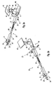
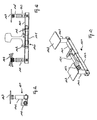
- Fig. 1 shows as an application example of the system 1 according to the invention a Divweg 2, which should allow the easy crossing a track system consisting of two slightly oblique to each other or running towards each other running tracks 50, 51.
- the system 1 according to the invention becomes a tread 3 formed, which is formed between the rails or laterally thereof and extends substantially transversely to the tracks 50, 51.
- the tread itself is formed by a plurality of module elements 10, which, for example, consist of gratings.
- the module elements 10 preferably have the same width, so that ultimately the width of the entire tread 3 is substantially constant.
- the length of the individual module elements 10 may, however, be different, depending on whether the module elements 10 are arranged between the rails of a track 50, 51, laterally thereof or between the tracks 50, 51. There is - as shown - of course, the possibility that the module elements 10 are designed trapezoidal or triangular. Finally, module elements of any shape can be used.
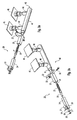
- the peculiarity of the system 1 according to the invention consists in the support or storage of the module elements 10, which takes place via mounting parts 20 which are closer in the Fig. 2a and 2b are shown and will be explained in detail below.
- the mounting parts 20 according to the invention are designed such that they allow a simple and fast attachment to the tracks 50, 51.
- a clamping mechanism is used, whose central components are claws 21 and 22, which are held by means of a tension spring 23 to tension, such that jamming with the rail is made possible.
- the claws 21 and 22 are respectively fixed to a quiver 24 and 25, wherein the two quivers 24 and 25 are designed such that they can telescopically engage with each other.
- the tension spring 23 is in this case connected to the two quivers 24, 25, wherein the connection with the front quiver 24 via a clamping screw 26 which passes through a front opening 27 of a arranged at the end of the quiver 24 U-profile 28 and here with a self-locking Nut 29 is screwed. With the help of a snap ring 30 unintentional loosening between the screw 26 and nut 29 is prevented.
- a lateral arm 40 in the form of a tube 41, on which the support element for supporting the module elements is arranged.
- the support element is in this case formed by a plate 45, which is arranged by means of a first nut 42 on a threaded pin 43, which in turn engages in a second nut 44.
- This nut 44 in turn forms the upper end portion of a vertical pipe section 46, wherein by means of the threaded pin 43 by a rotation of the plate 45, a height adjustment is made possible. As desired, accordingly, the height of the platen 45 can be adjusted within a certain range.
- FIG. 1 shows, to create the service path according to the invention several of the mounting parts 20 described attached to the rail feet and in this case form the support surface for the module elements 10. Outside the track area other support elements 15 can be used, which can be configured in any form. Preferably, in this case, the gratings are still connected to the mounting parts, for example. Via a screw to allow a fixed arrangement.
- the advantage of the solution according to the invention is that the system allows a very simple and fast creation of a service route or an escape or rescue route.
- the attachment of the mounting hardware 20 to the tracks can be done in a very simple and fast way. The same applies to the disassembly of the system, since only a few steps are required to remove the mounting hardware from the tracks.
- Fig. 3a and 3b show a further variant of a mounting member 20 according to the invention, in which the same elements are provided with the same reference numerals.
- this second variant of the boom 40 is designed to be longer than in the embodiment of Fig. 2a and 2b such that now two support plates 45 can be arranged side by side. This further expands the possibilities for arranging module elements.
- the show Fig. 4a and 4b a further embodiment of a mounting member 20 according to the invention in this mechanically robust variant of the boom is integrally connected to one of the two quivers 25.
- the claws 21, 22 are also designed to absorb extreme forces.
- the claw 22 connected to the quiver 25 of the boom is equipped with a, the quiver 25 integrally cross-section, for grasping the rail.
- the eyelet 34 which forms a point of attack for biasing the device, reinforced executed. It is formed by an axis which is inserted into two opposite bore openings of the claw 21 and welded there. Thus, the power of the eyelet 34 is no longer in the direction of the weld.
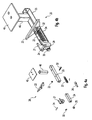
- FIGS. 5a and 5b show a further variant of a mounting part 120 according to the invention, which will be described below.
- a first peculiarity of this variant consists in the fact that the mounting member 120 is formed largely symmetrical, so provides support surfaces on both sides of the rail.
- two almost symmetrical arms 140 are provided, which in turn are formed as a quiver and telescopically mounted on a central piece 141. Accordingly, both arms 140 are displaceable relative to one another in the direction of the arrow in order to be able to be adapted to the dimensions of the rail foot. They have, as well as the previously discussed embodiments, claws 142 which engage around the rail foot.
- a screw connection is now provided, via which both arms 140 can be clamped to the rail foot. This connection will be later based on the FIGS. 6a to 6c described in more detail.
- each vertically aligned foot portions 145 are arranged, which engage with their lower end portions in the form of hollow sections boom 140.
- the foot portions 145 can be fixed accordingly to the arms.
- the foot portions 145 are hollow cylindrical - preferably with an internal thread - formed. Accordingly, they make it possible to engage in each case a threaded pin 146 (in the figures, this is shown only on one of the two arms), at the top of which Platen 147 is arranged.
- the illustrated screw connection between foot section 145 and threaded pin 146 allows a height adjustment of the support surface.
- the foot portions 145 are preferably formed of an insulating material. For example, it would be conceivable to use POM or PE.
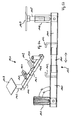
- FIG. 5b Another special feature of the illustrated embodiment is further that - as in FIG. 5b indicated - the foot sections used in the boom 145 before fixing a certain game and thus can be pivoted in a certain range relative to the arms 140 and tilted.
- the inclination of the foot portions 145 and thus of course the corresponding bearing surface of the support plate 147 can thus be easily changed.
- the rails are usually arranged slightly inclined to the inside of a track to complicate a derailment of rail vehicles. The inevitably resulting inclination of the rail foot can then be compensated by a corresponding adjustment of the foot sections 145, so that ultimately a desired horizontal bearing surface is created.
- a symmetrical configuration is provided.
- the claws 142 of the two arms 140 are in this case extended laterally and have corresponding through openings 150 (see FIG. 5a ).
- These openings 150 are penetrated by an elongated threaded bolt 151, which cooperates with a corresponding nut 152.
- the effort for mounting the mounting member 120 is thus slightly higher than in the variants of FIGS. 2 to 4 with the tension springs.
- the assembly of a single mounting part 120 is sufficient to provide a support surface on both sides of the rail.
- FIGS. 6a to 6c also provided an adjustment of the inclination of the support surface.
- this is not done via a corresponding inclination of the foot sections but via a corresponding attachment of the support plate 147 on the bolt 146.
- a pivotal mounting of the support plate 147 is ensured by a screw 155, so that again a desired adjustment can be made.
- This type of attachment of the mounting plate could be used in the above-described embodiments of the mounting parts - possibly even in addition to the adjustable arrangement of the foot areas - to basically ensure a horizontal orientation of the support plates.
- the present invention thus provides the opportunity to create running surfaces in track systems in a very simple and fast way.
Landscapes
- Engineering & Computer Science (AREA)
- Architecture (AREA)
- Civil Engineering (AREA)
- Structural Engineering (AREA)
- Emergency Lowering Means (AREA)
Abstract
Description
Die vorliegende Erfindung betrifft ein System zum Erstellen eines Flucht-, Rettungs- oder Dienstwegs in Gleisanlagen. Dabei soll in einfacher Weise eine Lauffläche im Gleisbereich gebildet werden.The present invention relates to a system for creating an escape, rescue or service route in track systems. It should be formed in a simple way, a tread in the track area.
Flucht- und Rettungswege im Bereich von Gleisanlagen der Bahn sind insbesondere für den Einsatz in Tunneln vorgesehen. Sie sollen im Falle eines Brands oder einer Havarie eine sichere Evakuierung von Personen aus dem Gefahrenbereich ermöglichen. Da in einem Tunnel der hierfür zur Verfügung stehende Platz in der Regel begrenzt ist, ist es oftmals erforderlich, die Personen nahe entlang der Gleise oder sogar zwischen den einzelnen Schienen aus dem Tunnel herauszuführen. Da eine Fortbewegung in dem herkömmlichen Gleisbett allerdings nur schwer möglich und ferner auch mit Gefahren verbunden ist, stellen derartige Flucht- und Rettungswegsysteme eine Lauffläche zur Verfügung, über welche Personen einfach aus dem Gefahrenbereich, insbesondere aus dem Tunnel heraus laufen können.Escape and rescue routes in the area of railway track systems are intended especially for use in tunnels. In the event of a fire or an accident, they should enable a safe evacuation of persons from the danger zone. Since the space available in a tunnel is usually limited in a tunnel, it is often necessary to lead people close to the track or even between the individual rails out of the tunnel. However, since locomotion in the conventional track bed is difficult and also associated with risks, provide such escape and Rettungswegsysteme a tread over which people can easily run out of the danger area, especially from the tunnel out.
Dienstwege wiederum dienen dazu, Personal bzw. allgemein Arbeitskräften die Möglichkeit zu eröffnen, sich bequem innerhalb des Gleisbereichs fortzubewegen. Beispielsweise soll ein bequemes Überqueren mehrerer Gleise ermöglicht werden.Service routes, in turn, serve to provide personnel or general workers with the ability to conveniently travel within the track area. For example, a comfortable crossing of several tracks is to be made possible.
Bislang war es bekannt, derartige Flucht- und Rettungswege bzw. Dienstwege durch Holzkonstruktionen zu realisieren. Diese wurden auf den Schwellen des Gleises montiert und bildeten eine sich im wesentlichen zwischen den zwei Gleisen erstreckende Lauffläche. Der Aufwand zur Installation derartiger Systeme war allerdings verhältnismässig gross, da die einzelnen Holzkomponenten jeweils einzeln und in mehreren Arbeitsschritten miteinander verbunden werden mussten. Ferner besteht generell das Bedürfnis, derartige Holzkonstruktionen zu vermeiden, um die Brandlast aus dem Tunnel zu entfernen. Da sämtliche Bauteile einer brandtechnischen Untersuchung unterzogen werden, sollte insbesondere auf Komponenten aus Holz gänzlich verzichtet werden.So far, it was known to implement such escape and rescue routes or service routes through wooden structures. These were mounted on the sleepers of the track and formed a tread extending substantially between the two tracks. The effort to install such systems, however, was relatively large, since the individual wood components had to be connected to each other individually and in several steps. Further, there is a general need to avoid such wood structures to remove the fire load from the tunnel. Since all components undergo a fire test, components made of wood should be completely dispensed with.
Eine weitere Problematik dieser bislang eingesetzten Lösung besteht schliesslich darin, dass das Holz äusseren Einflüssen ausgesetzt ist, welche im Laufe der Zeit zu Abnutzungserscheinungen führen und damit die Funktionalität des Rettungswegs beeinträchtigen. Auch wenn diese äusseren Einflüsse im Bereich eines Tunnels niedriger sind als im Freien, so führt dies doch dazu, dass der ordnungsgemässe Zustand dieser Systeme regelmässig überwacht werden muss und des öfteren Reparaturmassnahmen erforderlich sind.Another problem of this previously used solution is finally that the wood is exposed to external influences, which over time too Wear and tear and thus affect the functionality of the emergency route. Even though these external influences in the area of a tunnel are lower than in the open air, this does mean that the proper condition of these systems must be regularly monitored and repair measures often required.
Der vorliegenden Erfindung liegt deshalb die Aufgabe zugrunde, ein neuartiges System zur Bildung von Laufflächen innerhalb des Gleisbereichs anzugeben. Das System soll dabei möglichst einfach montiert werden können, um eine flexible Installation des Flucht- oder Rettungswegs bzw. Dienstwegs zu ermöglichen.The present invention is therefore based on the object of specifying a novel system for forming treads within the track area. The system should be as easy to install as possible to allow flexible installation of the escape or rescue route or service route.
Die Aufgabe wird durch ein System, welches die Merkmale des Anspruchs 1 aufweist, gelöst. Vorteilhafte Weiterbildungen der Erfindung sind Gegenstand der Unteransprüche.The object is achieved by a system having the features of claim 1. Advantageous developments of the invention are the subject of the dependent claims.
Das erfmdungsgemäße System zum Erstellen eines Flucht-, Rettungs- oder Dienstwegs beruht auf der Nutzung spezieller Montageteile, die Auflageelemente zum Lagern von Modul-Elementen aufweisen, wobei durch die Modul-Elemente eine Lauffläche gebildet wird. Die Montageteile zeichnen sich dabei dadurch aus, dass sie den Schienenfuß klemmend umgreifen und dementsprechend eine besonders einfache Montage bzw. Demontage ermöglicht ist.The erfmdungsgemäße system for creating an escape, rescue or service route is based on the use of special mounting parts having support elements for storing module elements, wherein a tread is formed by the module elements. The mounting parts are characterized by the fact that they clamp around the rail foot and accordingly a particularly simple assembly and disassembly is possible.
Erfindungsgemäß wird dementsprechend ein System zum Erstellen eines Flucht-, Rettungs- oder Dienstwegs in Gleisanlagen angegeben, welches eine zwischen den Schienen und/oder seitlich hiervon gebildete Lauffläche aufweist, wobei die Lauffläche durch eine Vielzahl von Modul-Elementen gebildet ist, welche auf mehreren Auflageelementen gelagert sind, und wobei die Auflageelemente an Montageteilen angeordnet sind, welche den Schienenfuß klemmend umgreifen.According to the invention, a system for creating an escape, rescue or service route in track systems is accordingly provided, which has a tread formed between the rails and / or laterally thereof, wherein the tread is formed by a plurality of module elements, which on several support elements are mounted, and wherein the support elements are arranged on mounting parts which engage around the rail foot by clamping.
Die Montageteile weisen vorzugsweise zwei Krallen auf, welche über eine Zugfeder miteinander verbunden sind. Insbesondere können die Krallen an zwei Köchern befestigt sein, welche teleskopisch ineinander greifen und an denen jeweils ein Ende der Zugfeder angreift. Diese Ausgestaltung ermöglicht ein einfaches und schnelles Anbringen der Montageteile an den Gleisen, wodurch letztendlich die gesamte Erstellung des Flucht-, Rettungs- oder Dienstwegs erleichtert wird. Alternativ hierzu wäre auch die Nutzung einer Schraubverbindung denkbar.The mounting parts preferably have two claws, which are connected to each other via a tension spring. In particular, the claws may be attached to two quivers which telescopically engage and engage one end of each of the tension springs. This design allows for easy and quick attachment of the mounting hardware to the tracks, which ultimately facilitates the overall creation of the escape, rescue or service route. Alternatively, the use of a screw connection would be conceivable.
Vorzugsweise sind die Auflageelemente jeweils an einem Ausleger angeordnet, der sich seitlich von dem Montageteil erstreckt, wobei insbesondere auch an beiden Seiten des Montageteils ein entsprechendes Auflageelement vorgesehen sein kann. Dabei kann ferner vorgesehen sein, dass die Auflageelemente höhenverstellbar ausgestaltet sind, um eine horizontale Ausrichtung der Lauffläche zu ermöglichen. Diese horizontale Ausrichtung kann ferner auch dadurch unterstützt werden, dass die Auflageelemente schwenkbar gelagert bzw. an einem schwenkbaren Halteteil angeordnet sind. Ferner könnte beispielsweise vorgesehen sein, dass der Ausleger mit einem der Köcher einstückig verbunden ist, um eine robuste Konstruktion und eine einfache Montage zu gewährleisten. Schließlich wäre es auch sinnvoll, im Bereich zwischen den Krallen und dem Auflageelement ein isolierendes Element anzuordnen, welches beispielsweise aus POM (Polyoxymethylen) oder PE (Polyethylen) besteht.Preferably, the support elements are each arranged on a boom, which extends laterally from the mounting part, in particular also on both sides the mounting part may be provided a corresponding support element. It can further be provided that the support elements are designed to be height adjustable in order to allow a horizontal alignment of the tread. This horizontal alignment can also be supported by the fact that the support elements are pivotally mounted or arranged on a pivotable holding part. Further, for example, it could be provided that the boom is integrally connected to one of the quivers in order to ensure a robust construction and easy installation. Finally, it would also be useful to arrange an insulating element in the region between the claws and the support element, which consists for example of POM (polyoxymethylene) or PE (polyethylene).
Die Modul-Elemente, welche in ihrer Gesamtheit die Lauffläche bilden, können bspw. durch Gitterroste gebildet sein.The module elements, which form the tread in their entirety, may for example be formed by gratings.
Nachfolgend soll die Erfindung anhand der beiliegenden Zeichnung näher erläutert werden. Es zeigen:
- Fig. 1
- in Aufsicht ein erfindungsgemäßes System zum Erstellen eines Flucht-, Rettungs- oder Dienstwegs in einer Gleisanlage;
- Fig. 2a und 2b
- ein erstes Ausführungsbeispiel eines erfindungsgemäßen Montageteils mit einem Auflageelement;
- Fig. 3a und 3b
- eine Variante des Montageteils von
Fig. 2 , welche zwei Auflageelemente aufweist; - Fig. 4a und 4b
- ein weiteres Ausführungsbeispiel eines erfindungsgemäßen Montageteils mit einem einstückig verbundenen Ausleger;
- Fig. 5a und 5b
- ein Ausführungsbeispiel eines symmetrischen Montageteils, welches zwei einander gegenüberliegende Auflageelemente aufweist; und
- Fig. 6a bis 6c
- eine weitere Variante eines symmetrischen Montageteils.
- Fig. 1
- in plan, an inventive system for creating an escape, rescue or service route in a track system;
- Fig. 2a and 2b
- a first embodiment of a mounting member according to the invention with a support element;
- Fig. 3a and 3b
- a variant of the mounting part of
Fig. 2 having two support elements; - Fig. 4a and 4b
- a further embodiment of a mounting member according to the invention with an integrally connected boom;
- Fig. 5a and 5b
- an embodiment of a symmetrical mounting part, which has two mutually opposite support elements; and
- Fig. 6a to 6c
- another variant of a symmetrical mounting part.
Die Lauffläche selbst wird durch eine Mehrzahl von Modul-Elementen 10 gebildet, welche bspw. aus Gitterrosten bestehen. Die Modul-Elemente 10 weisen vorzugsweise die gleiche Breite auf, so dass letztendlich die Breite der gesamten Lauffläche 3 im Wesentlichen gleichbleibend ist. Die Länge der einzelnen Modul-Elemente 10 kann allerdings unterschiedlich sein, abhängig davon, ob die Modul-Elemente 10 zwischen den Schienen eines Gleises 50, 51, seitlich hiervon oder zwischen den Gleisen 50, 51 angeordnet werden. Dabei besteht - wie dargestellt - selbstverständlich auch die Möglichkeit, dass die Modul-Elemente 10 trapezförmig oder dreieckig ausgestaltet sind. Letztendlich können Modul-Elemente einer beliebigen Form verwendet werden.The tread itself is formed by a plurality of
Die Besonderheit des erfindungsgemäßen Systems 1 besteht dabei in der Halterung bzw. Lagerung der Modul-Elemente 10, welche über Montageteile 20 erfolgt, die näher in den
Die erfindungsgemäßen Montageteile 20 sind dabei derart ausgestaltet, dass sie eine einfache und schnelle Befestigung an den Gleisen 50, 51 ermöglichen. Hierfür wird ein Spannmechanismus verwendet, dessen zentrale Bestandteile Krallen 21 bzw. 22 sind, welche mit Hilfe einer Zugfeder 23 auf Spannung gehalten werden, derart, dass ein Verklemmen mit dem Schienenfuß ermöglicht ist. Genau genommen sind die Krallen 21 und 22 jeweils an einem Köcher 24 bzw. 25 befestigt, wobei die beiden Köcher 24 und 25 derart ausgestaltet sind, dass sie teleskopisch ineinander greifen können. Die Zugfeder 23 ist hierbei mit den beiden Köchern 24, 25 verbunden, wobei die Verbindung mit dem vorderen Köcher 24 über eine Spannschraube 26 erfolgt, welche eine vordere Öffnung 27 eines am Endbereich des Köchers 24 angeordneten U-Profils 28 durchgreift und hier mit einer selbstsichernden Mutter 29 verschraubt ist. Mit Hilfe eines Sprengrings 30 wird ein unbeabsichtigtes Lösen zwischen Schraube 26 und Mutter 29 verhindert.The mounting
Beim zweiten Köcher 25 ist die Feder 23 mit Hilfe einer Öse 34 in eine Schraube 32 eingehängt, welche wiederum mit Hilfe einer Mutter 33 an dem Köcher 25 befestigt ist.When
Zum Montieren des Montageteils 20 an einem Schienenfuß wird dieses zunächst derart an den Schienenfuß angesetzt, dass die Kralle 22 den Seitenbereich des Schienenfußes umgreift. Die beiden ineinandergreifenden Köcher 24 und 25 sind hierbei unterhalb des Schienenfußes angeordnet. Mit Hilfe eines Zugwerkzeugs, welches an einer am Endbereich des Köchers 24 angeordneten Klammer 34 angreift, können dann die beiden Köcher 24 und 25 auseinander gezogen werden, bis die vordere Kralle 21 den gegenüberliegenden Seitenbereich des Schienenfußes umgreift. Aufgrund der durch die Zugfeder 23 ausgeübten Spannung wird hierbei ein sicherer Sitz des Montageteils 20 an dem Schienenfuß ermöglicht.To mount the mounting
Von dem Köcher 25 erstreckt sich ferner ein seitlicher Ausleger 40 in Form eines Rohrs 41, an dem das Auflageelement zur Lagerung der Modul-Elemente angeordnet ist. Das Auflageelement ist hierbei durch eine Platte 45 gebildet, welche mit Hilfe einer ersten Mutter 42 an einem Gewindezapfen 43 angeordnet ist, der wiederum in eine zweite Mutter 44 eingreift. Diese Mutter 44 wiederum bildet den oberen Endbereich eines vertikalen Rohrabschnitts 46, wobei mit Hilfe des Gewindezapfens 43 durch ein Verdrehen der Platte 45 eine Höhenverstellung ermöglicht wird. Je nach Wunsch kann dementsprechend die Höhe der Auflageplatte 45 in einem gewissen Bereich eingestellt werden.From the
Wie nunmehr
Der Vorteil der erfindungsgemäßen Lösung besteht darin, dass das System ein sehr einfaches und schnelles Erstellen eines Dienstwegs bzw. eines Flucht- oder Rettungswegs ermöglicht. Insbesondere die Befestigung der Montageteile 20 an den Gleisen kann in sehr einfacher und schneller Weise erfolgen. Gleiches gilt auch für die Demontage des Systems, da zum Entfernen der Montageteile von den Gleisen nur wenige Handgriffe erforderlich sind.The advantage of the solution according to the invention is that the system allows a very simple and fast creation of a service route or an escape or rescue route. In particular, the attachment of the mounting
Die
Ferner zeigen die
Die
Eine erste Besonderheit dieser Variante besteht dabei darin, dass das Montageteil 120 weitestgehend symmetrisch ausgebildet ist, also Auflageflächen an beiden Seiten der Schiene zur Verfügung stellt. Hierzu sind zwei nahezu symmetrisch ausgebildete Ausleger 140 vorgesehen, welche wiederum als Köcher ausgebildet und teleskopisch auf einem Mittelstück 141 gelagert sind. Beide Ausleger 140 sind dementsprechend in Pfeilrichtung relativ zueinander verschiebbar, um an die Abmessungen des Schienenfußes angepasst werden zu können. Sie weisen ebenso wie die zuvor diskutierten Ausführungsbeispiele Krallen 142 auf, welche den Schienenfuß umgreifen. Im Gegensatz zu dem zuvor beschriebenen Zugmechanismus mit einer Feder ist nunmehr allerdings eine Schraubverbindung vorgesehen, über welche beide Ausleger 140 mit dem Schienenfuß verklemmt werden können. Diese Verbindung wird später anhand der
An den beiden Enden der Ausleger 140 sind dann jeweils vertikal ausgerichtete Fußbereiche 145 angeordnet, welche mit ihren unteren Endbereichen in die als Hohlprofile ausgebildeten Ausleger 140 eingreifen. Mittels einer nicht dargestellten Schraube können dann die Fußabschnitte 145 entsprechend an den Auslegern fixiert werden. An ihrem oberen Ende sind die Fußbereiche 145 hohlzylindrisch - vorzugsweise mit einem Innengewinde - ausgebildet. Sie ermöglichen dementsprechend das Eingreifen jeweils eines Gewindestifts 146 (in den Figuren ist dieser lediglich an einem der beiden Ausleger dargestellt), an dessen Oberseite die Auflageplatte 147 angeordnet ist. Wiederum ermöglicht die dargestellte Schraubverbindung zwischen Fußabschnitt 145 und Gewindestift 146 eine Höhenanpassung der Auflagefläche. Die Fußabschnitte 145 sind hierbei vorzugsweise aus einem isolierenden Material gebildet. Denkbar wäre beispielsweise die Verwendung POM oder PE.At the two ends of the
Eine weitere Besonderheit des dargestellten Ausführungsbeispiels besteht ferner darin, dass - wie in
Auch bei der weiteren Variante eines Montageteils 120 entsprechend den
Ferner ist bei der Variante der
Letztendlich wird durch die vorliegende Erfindung also die Möglichkeit geschaffen, Laufflächen in Gleisanlagen in sehr einfacher und schneller Weise zu erstellen.Ultimately, the present invention thus provides the opportunity to create running surfaces in track systems in a very simple and fast way.
Claims (12)
wobei die Lauffläche (3) durch eine Vielzahl von Modul-Elementen (10) gebildet ist, welche auf mehreren Auflageelementen (45, 147) gelagert sind,
wobei die Auflageelemente (45, 147) an Montageteilen angeordnet (20, 120) sind, welche den Schienenfuß klemmend umgreifen.System (1) for creating an escape, rescue or service route (2) in track systems, with a running surface (3) formed between the rails and / or laterally thereof,
wherein the running surface (3) is formed by a multiplicity of module elements (10) which are mounted on a plurality of support elements (45, 147),
wherein the support elements (45, 147) arranged on mounting parts (20, 120) which engage around the rail foot by clamping.
dadurch gekennzeichnet,
dass die Montageteile (20, 120) zwei Krallen (21, 22) aufweisen, welche über eine Zugfeder (23) miteinander verbunden sind.System according to claim 1,
characterized,
in that the mounting parts (20, 120) have two claws (21, 22) which are connected to one another via a tension spring (23).
dadurch gekennzeichnet,
dass die Krallen (21, 22) an zwei Köchern (24, 25) befestigt sind, welche teleskopisch ineinandergreifen und an denen jeweils ein Ende der Zugfeder (23) angreift.System according to claim 2,
characterized,
in that the claws (21, 22) are fastened to two quivers (24, 25) which telescopically engage one another and on each of which one end of the tension spring (23) engages.
dadurch gekennzeichnet,
dass die Montageteile (20, 120) zwei Krallen (142) aufweisen, welche über eine Schraubverbindung miteinander verbunden sind.System according to claim 1,
characterized,
in that the mounting parts (20, 120) have two claws (142), which are connected to one another via a screw connection.
dadurch gekennzeichnet,
dass die Auflageelemente (45, 147) jeweils an einem Ausleger (40, 140) angeordnet sind, der sich seitlich von dem Montageteil (20, 120) erstreckt.System according to one of the preceding claims,
characterized,
in that the support elements (45, 147) are each arranged on a cantilever (40, 140) which extends laterally from the mounting part (20, 120).
dadurch gekennzeichnet,
dass an zwei einander gegenüberliegenden Enden des Montageteils (20, 120) jeweils ein Auflageelement (45, 147) angeordnet ist.System according to claim 4,
characterized,
in that a support element (45, 147) is arranged on two opposite ends of the mounting part (20, 120).
dadurch gekennzeichnet,
dass der bzw. die Ausleger (40, 140) und das Montageteil (20, 120) einstückig verbunden sind.System according to claim 5 or 6,
characterized,
that the boom (40, 140) and the mounting part (20, 120) are integrally connected.
dadurch gekennzeichnet,
dass die Auflageelemente (45, 147) höhenverstellbar sind.System according to one of the preceding claims,
characterized,
that the support members (45, 147) are adjustable in height.
dadurch gekennzeichnet,
dass die Auflageelemente (45, 147) schwenkbar angeordnet bzw. an einem schwenkbaren Halteelement (145) angeordnet sind.System according to one of the preceding claims,
characterized,
that the support members (45, 147) arranged to pivot or to a pivotable holding element (145) are arranged.
dadurch gekennzeichnet,
dass im Bereich zwischen den Krallen (21, 22, 142) und den Auflageelementen (45, 147) ein isolierendes Element angeordnet ist.System according to one of the preceding claims,
characterized,
in that an insulating element is arranged in the region between the claws (21, 22, 142) and the support elements (45, 147).
dadurch gekennzeichnet,
dass die Modul-Elemente (10) durch einen Gitterrost gebildet sind.System according to one of the preceding claims,
characterized,
that the module elements (10) are formed by a grating.
wobei das Montageteil (20) dazu ausgebildet ist, einen Schienenfuß klemmend zu umgreifen, und ferner ein Auflageelement (45) zur Lagerung eines eine Lauffläche bildenden Modul-Elements (10) aufweist.Mounting part (20) for creating an escape, rescue or service route (2) in track systems according to one of the preceding claims,
wherein the mounting member (20) is adapted to clampingly surround a rail foot, and further comprises a support member (45) for supporting a tread forming module element (10).
Applications Claiming Priority (2)
| Application Number | Priority Date | Filing Date | Title |
|---|---|---|---|
| DE102009015935 | 2009-04-02 | ||
| DE102009048149A DE102009048149A1 (en) | 2009-04-02 | 2009-10-02 | System for creating an escape, rescue or service route in track systems |
Publications (3)
| Publication Number | Publication Date |
|---|---|
| EP2241674A2 true EP2241674A2 (en) | 2010-10-20 |
| EP2241674A3 EP2241674A3 (en) | 2011-08-10 |
| EP2241674B1 EP2241674B1 (en) | 2014-04-09 |
Family
ID=42675143
Family Applications (1)
| Application Number | Title | Priority Date | Filing Date |
|---|---|---|---|
| EP20100001150 Not-in-force EP2241674B1 (en) | 2009-04-02 | 2010-02-04 | System for producing an escape, rescue or service path in rail assemblies |
Country Status (3)
| Country | Link |
|---|---|
| EP (1) | EP2241674B1 (en) |
| DE (1) | DE102009048149A1 (en) |
| DK (1) | DK2241674T3 (en) |
Cited By (3)
| Publication number | Priority date | Publication date | Assignee | Title |
|---|---|---|---|---|
| DE102015208944A1 (en) | 2014-05-14 | 2015-11-19 | Roof Safety Systems B.V. | A track comprising a track turnaround zone having a Y-shaped track pattern and provided with a protective structure for shielding the track in the track turnaround zone |
| WO2022130307A1 (en) * | 2020-12-18 | 2022-06-23 | Scuderi, Joseph | Device and method for securing functional objects between two rails |
| EP4311630A1 (en) * | 2022-07-27 | 2024-01-31 | EH Holding GmbH | Storage device |
Families Citing this family (1)
| Publication number | Priority date | Publication date | Assignee | Title |
|---|---|---|---|---|
| DE102016119058B3 (en) * | 2016-10-07 | 2017-12-21 | Patentgesellschaft Reimann Rosenquist Ug (Haftungsbeschränkt) | Holder for service route elements on tracks |
Family Cites Families (11)
| Publication number | Priority date | Publication date | Assignee | Title |
|---|---|---|---|---|
| CH661547A5 (en) * | 1981-03-20 | 1987-07-31 | Ampack Gleistechnik Ag | RAILROAD CROSSING. |
| DE9401902U1 (en) * | 1994-02-04 | 1994-03-17 | Wiebe Hermann Grundstueck | Mobile fence |
| DE9411177U1 (en) * | 1994-07-09 | 1994-09-15 | Hofmann Harald | Hot gas engine with rotating displacer |
| SI0969148T1 (en) * | 1995-10-10 | 2003-12-31 | Mueller Harald | Railroad security fence |
| DE19548857C2 (en) * | 1995-12-27 | 2000-03-09 | Envitec Umweltsyst Gmbh & Co | Cover for track systems |
| DE19609670C2 (en) * | 1996-03-12 | 1998-01-29 | Oskar Seidler Metallbau | Rail foot clamp |
| DE19751625C2 (en) * | 1997-01-25 | 2000-06-08 | Reinhard Friedrichs | Retaining bracket for supporting a barrier on a track rail |
| IT1310668B1 (en) * | 1999-08-03 | 2002-02-19 | Eleonora Fasano | SUPPORT SHELF CONNECTED WITH MECHANICAL CONNECTION TO RAILWAY RAILWORK COMMITTED TO CROSS RAIL. |
| DE20007465U1 (en) * | 2000-04-25 | 2000-08-10 | Intervia Gmbh & Co Kg | System for collecting contaminants, especially in the track area below rail vehicles, and holder for this |
| DE20116007U1 (en) * | 2001-09-28 | 2002-01-31 | Koehler & Seitz Beraten Und Pl | Device for securing falling edges and for establishing service routes next to tracks |
| DE102007009271A1 (en) * | 2006-08-02 | 2008-02-07 | WECO Bahnüberwege- und Auffangwannenbau GmbH | System for building emergency exits or escape routes in railway tracks, has bearing surface formed by multiple module elements arranged one behind other, and are connected with one another, which are held over one or more spacer |
-
2009
- 2009-10-02 DE DE102009048149A patent/DE102009048149A1/en not_active Withdrawn
-
2010
- 2010-02-04 DK DK10001150T patent/DK2241674T3/en active
- 2010-02-04 EP EP20100001150 patent/EP2241674B1/en not_active Not-in-force
Non-Patent Citations (1)
| Title |
|---|
| None |
Cited By (4)
| Publication number | Priority date | Publication date | Assignee | Title |
|---|---|---|---|---|
| DE102015208944A1 (en) | 2014-05-14 | 2015-11-19 | Roof Safety Systems B.V. | A track comprising a track turnaround zone having a Y-shaped track pattern and provided with a protective structure for shielding the track in the track turnaround zone |
| NL2012815B1 (en) * | 2014-05-14 | 2016-03-02 | Roof Safety Systems B V | Safety structure for shielding a railway line in a railway switch zone having a Y-shaped track pattern. |
| WO2022130307A1 (en) * | 2020-12-18 | 2022-06-23 | Scuderi, Joseph | Device and method for securing functional objects between two rails |
| EP4311630A1 (en) * | 2022-07-27 | 2024-01-31 | EH Holding GmbH | Storage device |
Also Published As
| Publication number | Publication date |
|---|---|
| EP2241674A3 (en) | 2011-08-10 |
| DE102009048149A1 (en) | 2010-10-07 |
| EP2241674B1 (en) | 2014-04-09 |
| DK2241674T3 (en) | 2014-07-07 |
Similar Documents
| Publication | Publication Date | Title |
|---|---|---|
| EP1960603B1 (en) | Apparatus for attachment of a mount for sensors, switching means and the like to rails | |
| EP2191069B1 (en) | System for fastening a rail and tensioning clamp for such a system | |
| EP2958761B1 (en) | Connection arrangement between a wheel-arm suspension of a vehicle and a flange | |
| EP2241674B1 (en) | System for producing an escape, rescue or service path in rail assemblies | |
| WO2018011309A1 (en) | Device for fastening a panel-shaped component in a receiving groove of a carrying rail | |
| EP3245114B1 (en) | Rail vehicle, in particular a locomotive | |
| EP0904459B1 (en) | Switching device for switch tongues | |
| EP3356599B1 (en) | System and fastening point for the screwless fastening of a rail for a rail vehicle | |
| DE102014108102B4 (en) | Rail safety device | |
| DE202009014226U1 (en) | System for creating an escape, rescue or service route in track systems | |
| DE10046764B4 (en) | Rollover protection for motor vehicles | |
| DE202010014460U1 (en) | Adjustable track spacer | |
| DE102014119213A1 (en) | Clamping device for stiffening hollow profiles | |
| EP2799620A1 (en) | Scaffold for creating structural systems | |
| DE102015205593B3 (en) | Brake Prellbock | |
| EP1470294B1 (en) | Device for adjusting the width of a track | |
| EP1817462B1 (en) | Suspension for a rail | |
| DE102009029074B4 (en) | Vibration absorber arrangement | |
| DE19962519C1 (en) | Holder for a lock box | |
| EP1281563B1 (en) | Tensioning device for contact wire | |
| CH711192B1 (en) | Device for braking a rail vehicle. | |
| AT517271B1 (en) | Brake unit for a track bender | |
| EP3118054A1 (en) | Current rail suspension on beams | |
| WO2020007524A1 (en) | Lateral support system and overhead line system | |
| EP3611305A1 (en) | Wall element for a traffic guiding and/or blocking wall |
Legal Events
| Date | Code | Title | Description |
|---|---|---|---|
| PUAI | Public reference made under article 153(3) epc to a published international application that has entered the european phase |
Free format text: ORIGINAL CODE: 0009012 |
|
| AK | Designated contracting states |
Kind code of ref document: A2 Designated state(s): AT BE BG CH CY CZ DE DK EE ES FI FR GB GR HR HU IE IS IT LI LT LU LV MC MK MT NL NO PL PT RO SE SI SK SM TR |
|
| AX | Request for extension of the european patent |
Extension state: AL BA RS |
|
| PUAL | Search report despatched |
Free format text: ORIGINAL CODE: 0009013 |
|
| AK | Designated contracting states |
Kind code of ref document: A3 Designated state(s): AT BE BG CH CY CZ DE DK EE ES FI FR GB GR HR HU IE IS IT LI LT LU LV MC MK MT NL NO PL PT RO SE SI SK SM TR |
|
| AX | Request for extension of the european patent |
Extension state: AL BA RS |
|
| RIC1 | Information provided on ipc code assigned before grant |
Ipc: E01C 9/04 20060101AFI20110701BHEP Ipc: E01C 9/10 20060101ALI20110701BHEP |
|
| 17P | Request for examination filed |
Effective date: 20120127 |
|
| GRAP | Despatch of communication of intention to grant a patent |
Free format text: ORIGINAL CODE: EPIDOSNIGR1 |
|
| INTG | Intention to grant announced |
Effective date: 20130819 |
|
| GRAP | Despatch of communication of intention to grant a patent |
Free format text: ORIGINAL CODE: EPIDOSNIGR1 |
|
| GRAS | Grant fee paid |
Free format text: ORIGINAL CODE: EPIDOSNIGR3 |
|
| INTG | Intention to grant announced |
Effective date: 20140127 |
|
| GRAA | (expected) grant |
Free format text: ORIGINAL CODE: 0009210 |
|
| AK | Designated contracting states |
Kind code of ref document: B1 Designated state(s): AT BE BG CH CY CZ DE DK EE ES FI FR GB GR HR HU IE IS IT LI LT LU LV MC MK MT NL NO PL PT RO SE SI SK SM TR |
|
| REG | Reference to a national code |
Ref country code: GB Ref legal event code: FG4D Free format text: NOT ENGLISH |
|
| REG | Reference to a national code |
Ref country code: CH Ref legal event code: EP Ref country code: AT Ref legal event code: REF Ref document number: 661441 Country of ref document: AT Kind code of ref document: T Effective date: 20140415 |
|
| REG | Reference to a national code |
Ref country code: IE Ref legal event code: FG4D Free format text: LANGUAGE OF EP DOCUMENT: GERMAN |
|
| REG | Reference to a national code |
Ref country code: DE Ref legal event code: R096 Ref document number: 502010006582 Country of ref document: DE Effective date: 20140522 |
|
| REG | Reference to a national code |
Ref country code: CH Ref legal event code: NV Representative=s name: FIAMMENGHI-FIAMMENGHI, CH |
|
| REG | Reference to a national code |
Ref country code: NL Ref legal event code: T3 |
|
| REG | Reference to a national code |
Ref country code: DK Ref legal event code: T3 Effective date: 20140703 |
|
| REG | Reference to a national code |
Ref country code: LT Ref legal event code: MG4D |
|
| PG25 | Lapsed in a contracting state [announced via postgrant information from national office to epo] |
Ref country code: FI Free format text: LAPSE BECAUSE OF FAILURE TO SUBMIT A TRANSLATION OF THE DESCRIPTION OR TO PAY THE FEE WITHIN THE PRESCRIBED TIME-LIMIT Effective date: 20140409 Ref country code: IS Free format text: LAPSE BECAUSE OF FAILURE TO SUBMIT A TRANSLATION OF THE DESCRIPTION OR TO PAY THE FEE WITHIN THE PRESCRIBED TIME-LIMIT Effective date: 20140809 Ref country code: GR Free format text: LAPSE BECAUSE OF FAILURE TO SUBMIT A TRANSLATION OF THE DESCRIPTION OR TO PAY THE FEE WITHIN THE PRESCRIBED TIME-LIMIT Effective date: 20140710 Ref country code: LT Free format text: LAPSE BECAUSE OF FAILURE TO SUBMIT A TRANSLATION OF THE DESCRIPTION OR TO PAY THE FEE WITHIN THE PRESCRIBED TIME-LIMIT Effective date: 20140409 Ref country code: NO Free format text: LAPSE BECAUSE OF FAILURE TO SUBMIT A TRANSLATION OF THE DESCRIPTION OR TO PAY THE FEE WITHIN THE PRESCRIBED TIME-LIMIT Effective date: 20140709 Ref country code: BG Free format text: LAPSE BECAUSE OF FAILURE TO SUBMIT A TRANSLATION OF THE DESCRIPTION OR TO PAY THE FEE WITHIN THE PRESCRIBED TIME-LIMIT Effective date: 20140709 |
|
| PG25 | Lapsed in a contracting state [announced via postgrant information from national office to epo] |
Ref country code: PL Free format text: LAPSE BECAUSE OF FAILURE TO SUBMIT A TRANSLATION OF THE DESCRIPTION OR TO PAY THE FEE WITHIN THE PRESCRIBED TIME-LIMIT Effective date: 20140409 Ref country code: SE Free format text: LAPSE BECAUSE OF FAILURE TO SUBMIT A TRANSLATION OF THE DESCRIPTION OR TO PAY THE FEE WITHIN THE PRESCRIBED TIME-LIMIT Effective date: 20140409 Ref country code: HR Free format text: LAPSE BECAUSE OF FAILURE TO SUBMIT A TRANSLATION OF THE DESCRIPTION OR TO PAY THE FEE WITHIN THE PRESCRIBED TIME-LIMIT Effective date: 20140409 Ref country code: ES Free format text: LAPSE BECAUSE OF FAILURE TO SUBMIT A TRANSLATION OF THE DESCRIPTION OR TO PAY THE FEE WITHIN THE PRESCRIBED TIME-LIMIT Effective date: 20140409 Ref country code: LV Free format text: LAPSE BECAUSE OF FAILURE TO SUBMIT A TRANSLATION OF THE DESCRIPTION OR TO PAY THE FEE WITHIN THE PRESCRIBED TIME-LIMIT Effective date: 20140409 |
|
| PG25 | Lapsed in a contracting state [announced via postgrant information from national office to epo] |
Ref country code: PT Free format text: LAPSE BECAUSE OF FAILURE TO SUBMIT A TRANSLATION OF THE DESCRIPTION OR TO PAY THE FEE WITHIN THE PRESCRIBED TIME-LIMIT Effective date: 20140811 |
|
| REG | Reference to a national code |
Ref country code: DE Ref legal event code: R097 Ref document number: 502010006582 Country of ref document: DE |
|
| PG25 | Lapsed in a contracting state [announced via postgrant information from national office to epo] |
Ref country code: CZ Free format text: LAPSE BECAUSE OF FAILURE TO SUBMIT A TRANSLATION OF THE DESCRIPTION OR TO PAY THE FEE WITHIN THE PRESCRIBED TIME-LIMIT Effective date: 20140409 Ref country code: RO Free format text: LAPSE BECAUSE OF FAILURE TO SUBMIT A TRANSLATION OF THE DESCRIPTION OR TO PAY THE FEE WITHIN THE PRESCRIBED TIME-LIMIT Effective date: 20140409 Ref country code: EE Free format text: LAPSE BECAUSE OF FAILURE TO SUBMIT A TRANSLATION OF THE DESCRIPTION OR TO PAY THE FEE WITHIN THE PRESCRIBED TIME-LIMIT Effective date: 20140409 Ref country code: SK Free format text: LAPSE BECAUSE OF FAILURE TO SUBMIT A TRANSLATION OF THE DESCRIPTION OR TO PAY THE FEE WITHIN THE PRESCRIBED TIME-LIMIT Effective date: 20140409 |
|
| PLBE | No opposition filed within time limit |
Free format text: ORIGINAL CODE: 0009261 |
|
| STAA | Information on the status of an ep patent application or granted ep patent |
Free format text: STATUS: NO OPPOSITION FILED WITHIN TIME LIMIT |
|
| 26N | No opposition filed |
Effective date: 20150112 |
|
| PG25 | Lapsed in a contracting state [announced via postgrant information from national office to epo] |
Ref country code: IT Free format text: LAPSE BECAUSE OF FAILURE TO SUBMIT A TRANSLATION OF THE DESCRIPTION OR TO PAY THE FEE WITHIN THE PRESCRIBED TIME-LIMIT Effective date: 20140409 |
|
| REG | Reference to a national code |
Ref country code: DE Ref legal event code: R097 Ref document number: 502010006582 Country of ref document: DE Effective date: 20150112 |
|
| PG25 | Lapsed in a contracting state [announced via postgrant information from national office to epo] |
Ref country code: BE Free format text: LAPSE BECAUSE OF NON-PAYMENT OF DUE FEES Effective date: 20150228 |
|
| PG25 | Lapsed in a contracting state [announced via postgrant information from national office to epo] |
Ref country code: SI Free format text: LAPSE BECAUSE OF FAILURE TO SUBMIT A TRANSLATION OF THE DESCRIPTION OR TO PAY THE FEE WITHIN THE PRESCRIBED TIME-LIMIT Effective date: 20140409 |
|
| PG25 | Lapsed in a contracting state [announced via postgrant information from national office to epo] |
Ref country code: LU Free format text: LAPSE BECAUSE OF FAILURE TO SUBMIT A TRANSLATION OF THE DESCRIPTION OR TO PAY THE FEE WITHIN THE PRESCRIBED TIME-LIMIT Effective date: 20150204 |
|
| PGFP | Annual fee paid to national office [announced via postgrant information from national office to epo] |
Ref country code: NL Payment date: 20150824 Year of fee payment: 6 |
|
| GBPC | Gb: european patent ceased through non-payment of renewal fee |
Effective date: 20150204 |
|
| PG25 | Lapsed in a contracting state [announced via postgrant information from national office to epo] |
Ref country code: MC Free format text: LAPSE BECAUSE OF FAILURE TO SUBMIT A TRANSLATION OF THE DESCRIPTION OR TO PAY THE FEE WITHIN THE PRESCRIBED TIME-LIMIT Effective date: 20140409 |
|
| PGFP | Annual fee paid to national office [announced via postgrant information from national office to epo] |
Ref country code: DK Payment date: 20150825 Year of fee payment: 6 Ref country code: DE Payment date: 20150731 Year of fee payment: 6 Ref country code: CH Payment date: 20150824 Year of fee payment: 6 |
|
| REG | Reference to a national code |
Ref country code: IE Ref legal event code: MM4A |
|
| REG | Reference to a national code |
Ref country code: FR Ref legal event code: ST Effective date: 20151030 |
|
| PGFP | Annual fee paid to national office [announced via postgrant information from national office to epo] |
Ref country code: AT Payment date: 20150820 Year of fee payment: 6 |
|
| PG25 | Lapsed in a contracting state [announced via postgrant information from national office to epo] |
Ref country code: IE Free format text: LAPSE BECAUSE OF NON-PAYMENT OF DUE FEES Effective date: 20150204 Ref country code: GB Free format text: LAPSE BECAUSE OF NON-PAYMENT OF DUE FEES Effective date: 20150204 |
|
| PG25 | Lapsed in a contracting state [announced via postgrant information from national office to epo] |
Ref country code: FR Free format text: LAPSE BECAUSE OF NON-PAYMENT OF DUE FEES Effective date: 20150302 |
|
| REG | Reference to a national code |
Ref country code: DE Ref legal event code: R119 Ref document number: 502010006582 Country of ref document: DE |
|
| REG | Reference to a national code |
Ref country code: DK Ref legal event code: EBP Effective date: 20160229 |
|
| REG | Reference to a national code |
Ref country code: CH Ref legal event code: PL |
|
| REG | Reference to a national code |
Ref country code: AT Ref legal event code: MM01 Ref document number: 661441 Country of ref document: AT Kind code of ref document: T Effective date: 20160204 |
|
| PG25 | Lapsed in a contracting state [announced via postgrant information from national office to epo] |
Ref country code: CH Free format text: LAPSE BECAUSE OF NON-PAYMENT OF DUE FEES Effective date: 20160229 Ref country code: LI Free format text: LAPSE BECAUSE OF NON-PAYMENT OF DUE FEES Effective date: 20160229 |
|
| REG | Reference to a national code |
Ref country code: NL Ref legal event code: MM Effective date: 20160301 |
|
| PG25 | Lapsed in a contracting state [announced via postgrant information from national office to epo] |
Ref country code: AT Free format text: LAPSE BECAUSE OF NON-PAYMENT OF DUE FEES Effective date: 20160204 |
|
| PG25 | Lapsed in a contracting state [announced via postgrant information from national office to epo] |
Ref country code: MT Free format text: LAPSE BECAUSE OF FAILURE TO SUBMIT A TRANSLATION OF THE DESCRIPTION OR TO PAY THE FEE WITHIN THE PRESCRIBED TIME-LIMIT Effective date: 20140409 |
|
| PG25 | Lapsed in a contracting state [announced via postgrant information from national office to epo] |
Ref country code: NL Free format text: LAPSE BECAUSE OF NON-PAYMENT OF DUE FEES Effective date: 20160301 Ref country code: DE Free format text: LAPSE BECAUSE OF NON-PAYMENT OF DUE FEES Effective date: 20160901 Ref country code: DK Free format text: LAPSE BECAUSE OF NON-PAYMENT OF DUE FEES Effective date: 20160229 |
|
| PG25 | Lapsed in a contracting state [announced via postgrant information from national office to epo] |
Ref country code: SM Free format text: LAPSE BECAUSE OF FAILURE TO SUBMIT A TRANSLATION OF THE DESCRIPTION OR TO PAY THE FEE WITHIN THE PRESCRIBED TIME-LIMIT Effective date: 20140409 Ref country code: HU Free format text: LAPSE BECAUSE OF FAILURE TO SUBMIT A TRANSLATION OF THE DESCRIPTION OR TO PAY THE FEE WITHIN THE PRESCRIBED TIME-LIMIT; INVALID AB INITIO Effective date: 20100204 |
|
| PG25 | Lapsed in a contracting state [announced via postgrant information from national office to epo] |
Ref country code: CY Free format text: LAPSE BECAUSE OF FAILURE TO SUBMIT A TRANSLATION OF THE DESCRIPTION OR TO PAY THE FEE WITHIN THE PRESCRIBED TIME-LIMIT Effective date: 20140409 |
|
| PG25 | Lapsed in a contracting state [announced via postgrant information from national office to epo] |
Ref country code: TR Free format text: LAPSE BECAUSE OF FAILURE TO SUBMIT A TRANSLATION OF THE DESCRIPTION OR TO PAY THE FEE WITHIN THE PRESCRIBED TIME-LIMIT Effective date: 20140409 |
|
| PG25 | Lapsed in a contracting state [announced via postgrant information from national office to epo] |
Ref country code: MK Free format text: LAPSE BECAUSE OF FAILURE TO SUBMIT A TRANSLATION OF THE DESCRIPTION OR TO PAY THE FEE WITHIN THE PRESCRIBED TIME-LIMIT Effective date: 20140409 |