EP3209428B1 - Pump dispensers - Google Patents
Pump dispensers Download PDFInfo
- Publication number
- EP3209428B1 EP3209428B1 EP15785175.9A EP15785175A EP3209428B1 EP 3209428 B1 EP3209428 B1 EP 3209428B1 EP 15785175 A EP15785175 A EP 15785175A EP 3209428 B1 EP3209428 B1 EP 3209428B1
- Authority
- EP
- European Patent Office
- Prior art keywords
- pump
- deformable
- chambers
- chamber
- actuator
- Prior art date
- Legal status (The legal status is an assumption and is not a legal conclusion. Google has not performed a legal analysis and makes no representation as to the accuracy of the status listed.)
- Active
Links
- 239000004743 Polypropylene Substances 0.000 claims description 11
- -1 polypropylene Polymers 0.000 claims description 11
- 229920001155 polypropylene Polymers 0.000 claims description 11
- 238000005452 bending Methods 0.000 claims description 5
- 238000005086 pumping Methods 0.000 claims description 4
- 230000015572 biosynthetic process Effects 0.000 description 8
- 238000005755 formation reaction Methods 0.000 description 8
- 239000000463 material Substances 0.000 description 4
- 239000012528 membrane Substances 0.000 description 4
- 239000002184 metal Substances 0.000 description 4
- 230000002093 peripheral effect Effects 0.000 description 4
- 230000000903 blocking effect Effects 0.000 description 3
- 239000012530 fluid Substances 0.000 description 3
- 238000007789 sealing Methods 0.000 description 3
- 238000013022 venting Methods 0.000 description 3
- 239000000806 elastomer Substances 0.000 description 2
- 229920001971 elastomer Polymers 0.000 description 2
- 239000007788 liquid Substances 0.000 description 2
- 230000007246 mechanism Effects 0.000 description 2
- 238000000465 moulding Methods 0.000 description 2
- 230000009471 action Effects 0.000 description 1
- 239000011324 bead Substances 0.000 description 1
- 230000008901 benefit Effects 0.000 description 1
- 230000008859 change Effects 0.000 description 1
- 238000006243 chemical reaction Methods 0.000 description 1
- 238000010276 construction Methods 0.000 description 1
- 239000000356 contaminant Substances 0.000 description 1
- 230000000994 depressogenic effect Effects 0.000 description 1
- 230000009969 flowable effect Effects 0.000 description 1
- 238000009434 installation Methods 0.000 description 1
- 229910052755 nonmetal Inorganic materials 0.000 description 1
- 230000037361 pathway Effects 0.000 description 1
- 239000004033 plastic Substances 0.000 description 1
- 229920003023 plastic Polymers 0.000 description 1
- 238000004064 recycling Methods 0.000 description 1
- 229920002725 thermoplastic elastomer Polymers 0.000 description 1
- 238000011144 upstream manufacturing Methods 0.000 description 1
Images


Classifications
-
- B—PERFORMING OPERATIONS; TRANSPORTING
- B05—SPRAYING OR ATOMISING IN GENERAL; APPLYING FLUENT MATERIALS TO SURFACES, IN GENERAL
- B05B—SPRAYING APPARATUS; ATOMISING APPARATUS; NOZZLES
- B05B11/00—Single-unit hand-held apparatus in which flow of contents is produced by the muscular force of the operator at the moment of use
-
- F—MECHANICAL ENGINEERING; LIGHTING; HEATING; WEAPONS; BLASTING
- F04—POSITIVE - DISPLACEMENT MACHINES FOR LIQUIDS; PUMPS FOR LIQUIDS OR ELASTIC FLUIDS
- F04B—POSITIVE-DISPLACEMENT MACHINES FOR LIQUIDS; PUMPS
- F04B43/00—Machines, pumps, or pumping installations having flexible working members
-
- B—PERFORMING OPERATIONS; TRANSPORTING
- B05—SPRAYING OR ATOMISING IN GENERAL; APPLYING FLUENT MATERIALS TO SURFACES, IN GENERAL
- B05B—SPRAYING APPARATUS; ATOMISING APPARATUS; NOZZLES
- B05B11/00—Single-unit hand-held apparatus in which flow of contents is produced by the muscular force of the operator at the moment of use
- B05B11/01—Single-unit hand-held apparatus in which flow of contents is produced by the muscular force of the operator at the moment of use characterised by the means producing the flow
- B05B11/10—Pump arrangements for transferring the contents from the container to a pump chamber by a sucking effect and forcing the contents out through the dispensing nozzle
- B05B11/1028—Pumps having a pumping chamber with a deformable wall
- B05B11/1032—Pumps having a pumping chamber with a deformable wall actuated without substantial movement of the nozzle in the direction of the pressure stroke
-
- B—PERFORMING OPERATIONS; TRANSPORTING
- B05—SPRAYING OR ATOMISING IN GENERAL; APPLYING FLUENT MATERIALS TO SURFACES, IN GENERAL
- B05B—SPRAYING APPARATUS; ATOMISING APPARATUS; NOZZLES
- B05B11/00—Single-unit hand-held apparatus in which flow of contents is produced by the muscular force of the operator at the moment of use
- B05B11/0005—Components or details
- B05B11/0037—Containers
- B05B11/0039—Containers associated with means for compensating the pressure difference between the ambient pressure and the pressure inside the container, e.g. pressure relief means
- B05B11/0041—Containers associated with means for compensating the pressure difference between the ambient pressure and the pressure inside the container, e.g. pressure relief means compensating underpressure without contact of the fluid remaining in the container with the atmospheric air
-
- B—PERFORMING OPERATIONS; TRANSPORTING
- B05—SPRAYING OR ATOMISING IN GENERAL; APPLYING FLUENT MATERIALS TO SURFACES, IN GENERAL
- B05B—SPRAYING APPARATUS; ATOMISING APPARATUS; NOZZLES
- B05B11/00—Single-unit hand-held apparatus in which flow of contents is produced by the muscular force of the operator at the moment of use
- B05B11/01—Single-unit hand-held apparatus in which flow of contents is produced by the muscular force of the operator at the moment of use characterised by the means producing the flow
- B05B11/10—Pump arrangements for transferring the contents from the container to a pump chamber by a sucking effect and forcing the contents out through the dispensing nozzle
- B05B11/1001—Piston pumps
- B05B11/1015—Piston pumps actuated without substantial movement of the nozzle in the direction of the pressure stroke
-
- B—PERFORMING OPERATIONS; TRANSPORTING
- B05—SPRAYING OR ATOMISING IN GENERAL; APPLYING FLUENT MATERIALS TO SURFACES, IN GENERAL
- B05B—SPRAYING APPARATUS; ATOMISING APPARATUS; NOZZLES
- B05B11/00—Single-unit hand-held apparatus in which flow of contents is produced by the muscular force of the operator at the moment of use
- B05B11/01—Single-unit hand-held apparatus in which flow of contents is produced by the muscular force of the operator at the moment of use characterised by the means producing the flow
- B05B11/10—Pump arrangements for transferring the contents from the container to a pump chamber by a sucking effect and forcing the contents out through the dispensing nozzle
- B05B11/1028—Pumps having a pumping chamber with a deformable wall
- B05B11/1029—Pumps having a pumping chamber with a deformable wall actuated by a lever
- B05B11/103—Pumps having a pumping chamber with a deformable wall actuated by a lever without substantial movement of the nozzle in the direction of the pressure stroke
-
- B—PERFORMING OPERATIONS; TRANSPORTING
- B05—SPRAYING OR ATOMISING IN GENERAL; APPLYING FLUENT MATERIALS TO SURFACES, IN GENERAL
- B05B—SPRAYING APPARATUS; ATOMISING APPARATUS; NOZZLES
- B05B11/00—Single-unit hand-held apparatus in which flow of contents is produced by the muscular force of the operator at the moment of use
- B05B11/01—Single-unit hand-held apparatus in which flow of contents is produced by the muscular force of the operator at the moment of use characterised by the means producing the flow
- B05B11/10—Pump arrangements for transferring the contents from the container to a pump chamber by a sucking effect and forcing the contents out through the dispensing nozzle
- B05B11/1028—Pumps having a pumping chamber with a deformable wall
- B05B11/1035—Pumps having a pumping chamber with a deformable wall the pumping chamber being a bellow
-
- B—PERFORMING OPERATIONS; TRANSPORTING
- B05—SPRAYING OR ATOMISING IN GENERAL; APPLYING FLUENT MATERIALS TO SURFACES, IN GENERAL
- B05B—SPRAYING APPARATUS; ATOMISING APPARATUS; NOZZLES
- B05B11/00—Single-unit hand-held apparatus in which flow of contents is produced by the muscular force of the operator at the moment of use
- B05B11/01—Single-unit hand-held apparatus in which flow of contents is produced by the muscular force of the operator at the moment of use characterised by the means producing the flow
- B05B11/10—Pump arrangements for transferring the contents from the container to a pump chamber by a sucking effect and forcing the contents out through the dispensing nozzle
- B05B11/1042—Components or details
- B05B11/1059—Means for locking a pump or its actuation means in a fixed position
Definitions
- This invention relates to pump dispensers, of the kind having a pump module mounted on a container of a flowable product to be dispensed.
- the basic functional elements are a pump chamber of variable volume, having an inlet from the container and an outlet to a discharge opening, and an actuator operable to change the volume of the pump chamber to draw product into the pump chamber and expel the product through the discharge opening.
- At least the inlet and often also the outlet generally have one-way valves for efficient action.
- the simplest and cheapest pumps are movable-nozzle piston-and-cylinder pumps in which a reciprocable plunger carries a piston which works in a cylinder defined by a body of the pump and which fixes onto the container neck.
- a ball valve is provided for the inlet, and often for the outlet.
- a return spring acts between the pump body and plunger to urge the latter to its extended position, automatically re-filling the pump chamber after each dispensing stroke.
- Deformable pump chambers typically using bellows constructions and/or elastomer or thermoplastic elastomer materials, have been proposed and used. However these materials are expensive as well as usually non-recyclable, while bellows-form chambers are seldom effective.
- WO2011/064584 describes pump dispensers in which two pump chambers are defined by an insert of resiliently flexible material fitted into the container neck beneath a depressible actuator cap.
- the insert defines an inlet from the container and has a generally conical upper diaphragm separating its interior into two pump chambers.
- One chamber may be for air, to mix at the outlet with liquid pumped from the other chamber.
- both chambers may be for liquid with connection openings being formed through the diaphragm for them to act as a single chamber.
- US4867347 proposed a pump chamber having a resiliently restorable flexible wall which could be made from standard plastics such as polypropylene.
- Restoring force is provided by a special form of the flexible wall, comprising at least one facet having a concave boundary and a curved surface portion interrupting the facet to induce bending thereof in the dispensing stroke, this bending producing a strong restoring force tending to restore the flexible wall to the rest condition.
- the curved surface portion - typically a cylindrical surface portion - is axially inclined to the facet and meets it along the concave boundary.
- the flexible wall has the shape of a polygonal pyramid with plural facets. This structure has the advantage that it can be molded integrally with adjacent components, such as thicker portions for guiding the movement or mounting the flexible wall.
- the restoring force achieved is often inadequate and the design did not become commercially used.
- the invention provides a pump dispenser as defined in claim 1, comprising a pump having a deformable pump chamber with a valved inlet and an outlet, and a pump actuator operable relative to a body of the pump to vary the volume of the deformable pump chamber for pumping, wherein the pump chamber comprises first and second communicating part-chambers each having a respective deformable chamber wall, characterised in that the first and second part-chambers are compressed towards one another by the pump actuator in a dispensing stroke, and a non-deformable connecting conduit communicates between them whereby the connecting conduit drives deformation of the respective deformable chamber walls as the first and second part-chambers are pushed together.
- the first and second part-chambers may be disposed so as both to be compressed at the same time by the pump actuator in the dispensing stroke thereof.
- the first and second part-chambers may be disposed in line between the pump body and the actuator, which is moved towards the pump body in the dispensing stroke.
- One or both of the first and second part-chambers may have a rigid wall portion and a deformable wall portion.
- the first and second part-chambers may be disposed with the respective deformable wall portions facing each other.
- the pump inlet leads into one of the part-chambers and the outlet, also desirably valved, leads out from the other so that dispensed product passes through the part-chambers in series.
- the deformable wall of at least one and preferably both of the first and second part-chambers is resiliently deformable and tends to recover to an extended position of the part-chamber after actuation in the dispensing stroke. More preferably the dispenser relies on the resilience of the resiliently deformable walls to return the pump to the extended or rest condition after a dispensing stroke.
- the pump may have no return spring other than the chambers themselves.
- one or both of the part-chambers has a resiliently restorable flexible wall comprising a plurality of mutually angled facets.
- a non-elastomeric flexible wall comprising at least one facet having a concave boundary and a curved surface portion which interrupts the facet to induce bending thereof in the dispensing stroke, this bending producing a reaction force tending to restore the flexible wall to the rest/extended condition.
- the curved surface portion may be a cylindrical surface portion, e.g. axially inclined to the facet, and meeting it along the concave boundary.
- One or both flexible walls may be made of polypropylene.
- the flexible walls of the first and second chambers may be formed in one piece with one another, and/or one of them may be formed in one piece with the connecting conduit.
- the part-chambers may be constituted by a rigid body member, an actuator member reciprocable relative to the rigid body member, a first one-piece resiliently deformable wall component defining the first part-chamber in combination with the body member and a second one-piece resiliently deformable wall component defining the second part-chamber in combination with the actuator member, the connecting conduit being a preferably rigid tube extending between them e.g. in the direction of reciprocation.
- the actuator is preferably a reciprocable plunger.
- the actuator and pump body enclose the part-chambers and conduit between them.
- One or both of actuator and pump body may have cap or cup form.
- all of the above-mentioned pump components and more preferably also an inlet valve and an outlet valve are non-metal, and preferably without elastomer components.
- Most desirably all of the mentioned components are of polypropylene.
- a preferred feature relates to sealing a pump against leakage.
- the pump has a plunger (the actuator) biased to an extended position relative to the pump body.
- the fluid pathway in the pump passes through a restricted opening in a pump component which is movable relative to the plunger in the direction of plunger movement.
- Another pump component such as the plunger or body, comprises or carries an enlarged blocking element which enters and blocks said restricted opening in the extended position of the plunger, but not in the retracted or depressed position thereof.
- the plunger may have an internal projection with an enlarged blocking element inside a deformable pump chamber, projecting through the pump chamber in the direction of plunger movement and entering a restricted opening on the opposite side of the pump chamber.
- a pump plunger (the actuator) is reciprocable in a pumping stroke relative to the pump body.
- One of the plunger and body (the outside component) has an open mouth that surrounds and moves onto the other of the plunger and body (the inside component) in the pumping stroke.
- a locking mechanism comprises selectively engageable interlock formations on the outside of the inside component and preferably on the inside of the outside component, e.g. at or adjacent the mouth of the latter.
- the interlock formations may be selectively engageable/ disengageable by rotating the components relative to one another around the plunger axis.
- an interlock formation on the outside component that normally makes a stop engagement with the inside component during dispensing to prevent escape of the plunger is alternatively engageable with different formations of the inside component to prevent actuation.
- venting of air i.e. the controlled admission of air into a container of the pump dispenser to compensate for the volume of product dispensed.
- a vent path enters the dispenser between a container neck and a closure component of the pump secured onto the neck e.g. by a screw thread.
- the closure component also comprises an inlet formation of the pump, including an inlet opening, and a valve unit is disposed at the inlet.
- the valve unit comprises a layer portion lying in proximity to the closure component adjacent the inlet but also having a region spaced from the closure component by a clearance.
- the vent path enters the clearance between the valve unit layer portion and the closure component, and runs to the inlet opening behind the valve unit.
- the dispenser may comprise a vent valve for opening through said closure component into said clearance.
- the vent valve may be comprised in a body formed in one piece with the inlet valve and optionally a surround thereof comprising said layer portion.
- Fig. 1 shows a bottle 1 having a pump 2 mounted on its neck.
- Fig. 2 shows that the bottle neck carries an external securing thread 13.
- the pump 2 has a pump body 4 by which it is secured to the container.
- the body includes a cap portion comprising a cylindrical cap skirt 41 and a cover flange 43, the skirt 41 having internal threads 42 which engage the neck threads 13.
- the cover flange 43 extends radially in across the neck edge and turns down to a central inlet recess 48 which projects down into the container neck and has at its bottom an inlet hole 45, surrounded by an inlet valve seat 46 ( Fig. 6 ), with a dip tube socket 47 projecting below (the dip tube is present but not shown).
- the cover flange 43 extends radially slightly out beyond the cap skirt 41 and meets an upstanding support surround 49 which locates other components described below.
- a plunger actuator or actuator cap 3 is mounted over the pump body 4, and has a generally enclosed cylindrical side wall 31 and flat top wall 310 and is open at the bottom, at a downward mouth 37.
- the downward mouth and cylindrical side wall 31 fit round the support surround 49 of the pump body so that the actuator cap can slide up and down over the body 4, altering the height and volume of the cavity defined between them.
- the top of the actuator cap 3 has a nozzle or spout 32 which opens laterally and connects to the interior via a discharge channel 321 which connects in turn to an annular discharge space 322 inside the cap.
- Upper and lower pump chamber-defining members 15,25 are contained in the cavity defined between the actuator cap 3 and pump body 4, and define or enclose, in combination with the cap and body respectively, a top part-chamber 150 and a bottom part-chamber 250 which communicate through a connecting tube 20. See Figs. 3 and 4 .
- Each chamber-defining member 15,25 comprises a resiliently deformable membrane or flexible wall 156,256 connected integrally to a respective peripheral securing ring 151,251 by which it is secured against the side wall of the cavity between the actuator cap 3 and the pump body 4.
- the lower member 25 has its flexible wall/membrane 256 formed integrally with the thicker peripheral securing ring 251 which anchors inside the support surround 49 of the pump body 4 to hold it in place.
- the flexible wall 256 is generally in the form of a downwardly directed conical polygon or polygonal pyramid with five facets 257, best seen in Fig. 3 .
- the respective facets are substantially planar in the rest condition shown in Figs. 2 and 3 , each angled at about 30° to the plane common to their bases.
- each facet 257 At the radially inner (higher) part of each facet 257 it is intersected, along a concave boundary 258, by a cylindrical surface portion 259 the central line of which lies in the same radial plane of the pyramid as does the centre line of each facet 257.
- the centre of the element Inward of the cylindrical surface portions the centre of the element has a thicker-walled form 252 including an axial spigot 253 communicating through the flexible wall into the part-chamber formed between the flexible wall and the pump body beneath.
- the upper resiliently deformable member 15 has a similar form as regards the deformable wall portion, with facets 157 intersecting with cylindrical segments 159, but the peripheral structure differs.
- the outermost structure is a stiff cylindrical securing ring 151, deeper than that of the lower member, and this fits up against the top end of the actuator cap 3 with its top edge held in an annular groove 38. It connects to the flexible faceted surface through a narrow annular connecting web in a radial plane. From the inside edge of this web the resiliently deformable wall 156 extends inwardly and downwardly, inverted relative to the lower member 25. Above the thick web there is an upstanding cylindrical skirt formation 155, tapering in thickness, which constitutes an outlet valve flap.
- valve seat 34 provided by a generally cylindrical downward projection from the top wall 310 of the actuator cap 3.
- the top of the actuator cap, the upstanding upward valve flap 155, the securing ring 151 and the integral radial web define between them the annular discharge channel 322 or discharge chamber which extends around the top of the cap and leads to the circumferentially-local spout discharge channel 321.
- the upper member 15 comprises integrally the elongate axial connecting tube 20 which at its inner (upper) end opening has an in-turned annular lip or bead 158 and at its lower end plugs onto the central spigot 253 of the lower flexible member 25.
- a sealing pin 33 with an enlarged blocking end 331 projects down into the top opening of the connecting tube 20. Its enlarged end is a force fit past the in-turned lip 158 there, but fits with clearance in the main bore of the connecting tube 20 so that fluid can communicate through except when the actuator cap 3 is at its highest extension - as in Fig. 2 - when the enlarged pin end blocks the top of the connecting tube and forms a seal preventing the escape of product from the pump; useful when it is carried.
- Fig. 3 shows that the upper and lower deformable pump-chamber-defining members 15,25 are moulded initially in one piece, desirably from polypropylene, connected by an integral link piece 160. They can remain connected by this when they are folded face to face to plug the connecting tube 20 onto the spigot 253 as seen in Fig. 4 .
- the overall compressible pump chamber is constituted in combination by the top pump chamber 150, defined between the upper deformable member 15 and the top of the actuator cap 3, the lower pump chamber 250 defined by the lower deformable member 25 and the pump body 4 and inlet valve below, and the connecting tube 20 which is however not compressible.
- the connecting tube 20 which is however not compressible.
- polypropylene is used also for the inlet-side valve formations to be described next, so that all the elements for the pump are of polypropylene which is notably economical and recycling-friendly.
- the pump body 4 has a central inlet recess 48 to seat the inlet valve.
- the surrounding cover flange portion 43 of the body has a set of vent holes 44 which - as seen from Fig. 2 - communicate with the exterior through the (non-airtight) connecting threads of the body and container neck.
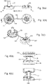
- the inlet valve 51 is comprised in a larger valve body 5, a one-piece polypropylene moulding shown in Fig. 7 .
- On the left in the figure is an inlet valve surround element 52 with a peripheral securing ring 53 that fits around inside the securing ring 251 of the lower pump chamber member.
- a central recessed portion 54 This is connected to a central recessed portion 54 via a sloping frusto-conical cover region 59 which, as seen in Fig. 2 , defines an annular clearance above the vent holes 44 in the body cover flange 43.
- the central recessed part 54 of the valve body surround sits conformingly down in the corresponding central inlet recess 48 of the body 4.
- the inlet valve is a flat flap 51 connected to the surround by integral thin flexible legs 511 so that it can be lifted off the corresponding seat 46 of the body by forward fluid pressure drawn up through the inlet 45.
- the valve body recess region 54 fits loosely in the body inlet recess 48 so that air can get between them from the previously-mentioned clearance to upstream of the inlet valve, compensating for dispensed product. This is facilitated - see Fig. 6(b) - by vent notches 40 at the angle where the flange 43 meets the inlet recess 48.
- a vent seal is provided.
- it is by an annular vent valve flap 55 formed in one piece with the inlet valve body 5 - the vent valve part and the inlet valve part are joined by a nexus piece 591 in the moulding.
- the vent valve flap 55 is connected by a series of thin flexible legs 551 to an inner holding ring 56.
- the vent valve part is folded under the inlet valve part and the holding ring 56 fitted up around the recessed part 54 of the inlet valve surround.
- the vent valve flap 55 and its holding ring 56 can be slid up level with the outer support ring 53, as shown in Fig.
- vent valve flap 55 when installed on the pump body the vent valve flap 55 overlies the body flange vent holes 44 to prevent escape of material while allowing air to enter.
- the retaining ring 251 of the lower deformable member 25 is sandwiched between the retaining ring 53 of the inlet valve surround 52 and the support surround 49.
- a further feature of interest is locking of the actuator cap 3.
- the actuator cap 3 Around the inner periphery of its downward mouth 37 it has a set of four inwardly-projecting circumferentially-extending retaining lugs 36. These are caught under the outside edge of the pump body flange 43 to hold the actuator cap down in place on the body against an expansion tendency of the flexible chamber walls, which are slightly precompressed.
- the retaining lugs 36 are also engageable above a corresponding set of locking shelves 50, which project down below the support surround 49 of the pump body 4 and then prevent depression of the actuator i.e. lock the dispenser.
- the left side of Fig. 2 shows the engagement.
- outlet valve could take other forms, but preferably with the movable element of the valve such as a flap being formed integrally with the pump chamber component or adjacent actuator component to minimise the component count.
Landscapes
- Engineering & Computer Science (AREA)
- Mechanical Engineering (AREA)
- General Engineering & Computer Science (AREA)
- Reciprocating Pumps (AREA)
- Closures For Containers (AREA)
- Containers And Packaging Bodies Having A Special Means To Remove Contents (AREA)
Applications Claiming Priority (2)
| Application Number | Priority Date | Filing Date | Title |
|---|---|---|---|
| GB1418658.9A GB2531997B (en) | 2014-10-20 | 2014-10-20 | Pump dispenser with deformable pump chamber wall |
| PCT/GB2015/053086 WO2016063015A1 (en) | 2014-10-20 | 2015-10-16 | Pump dispensers |
Publications (2)
| Publication Number | Publication Date |
|---|---|
| EP3209428A1 EP3209428A1 (en) | 2017-08-30 |
| EP3209428B1 true EP3209428B1 (en) | 2022-09-28 |
Family
ID=52013323
Family Applications (1)
| Application Number | Title | Priority Date | Filing Date |
|---|---|---|---|
| EP15785175.9A Active EP3209428B1 (en) | 2014-10-20 | 2015-10-16 | Pump dispensers |
Country Status (8)
| Country | Link |
|---|---|
| US (2) | US10549299B2 (ja) |
| EP (1) | EP3209428B1 (ja) |
| JP (1) | JP2017535422A (ja) |
| CN (1) | CN107074412B (ja) |
| AU (1) | AU2015334726A1 (ja) |
| CA (1) | CA2964820A1 (ja) |
| GB (1) | GB2531997B (ja) |
| WO (1) | WO2016063015A1 (ja) |
Families Citing this family (14)
| Publication number | Priority date | Publication date | Assignee | Title |
|---|---|---|---|---|
| GB2531997B (en) | 2014-10-20 | 2018-08-01 | Rieke Packaging Systems Ltd | Pump dispenser with deformable pump chamber wall |
| GB201518910D0 (en) | 2015-10-26 | 2015-12-09 | Rieke Packaging Systems Ltd | Dispensers |
| CN114521185B (zh) * | 2019-07-23 | 2024-08-06 | 里克包装系统有限公司 | 具有内部塞件密封的全聚合物泵分配器 |
| CN114450093B (zh) * | 2019-07-23 | 2024-03-19 | 里克包装系统有限公司 | 聚合物泵分配器 |
| IT201900021321A1 (it) | 2019-11-15 | 2021-05-15 | Taplast Srl | Pompa a soffietto bloccabile in posizione ritratta |
| EP4065285B1 (en) | 2019-11-27 | 2024-06-26 | Rieke Packaging Systems Limited | Continuous spray trigger dispenser |
| WO2022038194A1 (en) | 2020-08-18 | 2022-02-24 | Rieke Packaging Systems Limited | Modular, adjustable force, all-polymer helical biasing member and pump dispenser incorporating same |
| WO2022049566A1 (en) * | 2020-09-01 | 2022-03-10 | Manjushree Technopack Limited | Pump for dispensing viscous fluid from a container |
| US11660627B2 (en) | 2020-12-15 | 2023-05-30 | The Procter & Gamble Company | Recyclable pump dispenser |
| US11338310B1 (en) * | 2021-01-25 | 2022-05-24 | The Procter & Gamble Company | Manually operated dispensing pump |
| US11267009B1 (en) * | 2021-01-25 | 2022-03-08 | The Procter & Gamble Company | Manually operated dispensing pump |
| CN118660765A (zh) | 2021-11-19 | 2024-09-17 | 里克包装系统有限公司 | 用于泡沫产品的单一聚合物往复分配器 |
| CN118660766A (zh) | 2021-12-13 | 2024-09-17 | 里克包装系统有限公司 | 用于粘性流体和油的单一聚合物分配器 |
| WO2024153698A1 (en) | 2023-01-17 | 2024-07-25 | Rieke Packaging Systems Limited | Retainer and inlet valve for reciprocating pumps |
Citations (1)
| Publication number | Priority date | Publication date | Assignee | Title |
|---|---|---|---|---|
| WO2011064584A1 (en) * | 2009-11-26 | 2011-06-03 | Leafgreen Limited | Manual pump dispenser and a method of manufacturing the same |
Family Cites Families (36)
| Publication number | Priority date | Publication date | Assignee | Title |
|---|---|---|---|---|
| DE1728474C3 (de) * | 1967-01-17 | 1978-08-17 | Pfeiffer Zerstaeuber-Vertriebsgesellschaft Mbh & Co Kg, 7760 Radolfzell | Zerstäuberpumpe |
| BE752932A (fr) * | 1969-07-07 | 1970-12-16 | Pulverisation Par Abreviation | Vaporisateur a tube plongeur |
| US3759426A (en) * | 1972-09-08 | 1973-09-18 | N Kane | Manually-operated liquid dispenser |
| FR2224007A5 (ja) * | 1973-03-28 | 1974-10-25 | Step Soc Tech Pulverisation | |
| US4071172A (en) * | 1976-04-07 | 1978-01-31 | Balogh Stephen M | Manually operated liquid dispenser |
| US4162746A (en) * | 1977-06-22 | 1979-07-31 | Diamond International Corporation | Liquid dispenser locking means |
| IT1087232B (it) * | 1977-11-17 | 1985-06-04 | Coster Tecnologie Speciali Spa | Pompetta erogatrice a comando manuale per contenitori di liquidi |
| US4218198A (en) * | 1978-11-02 | 1980-08-19 | Security Plastics, Inc. | Pump having non-throttling peripheral valve |
| US4410107A (en) * | 1981-12-18 | 1983-10-18 | Corsette Douglas Frank | Liquid dispensing pump |
| IT8221773V0 (it) | 1982-05-04 | 1982-05-04 | Sar Spa | Pompetta a mano con cappuccio erogatore vincolabile in posizione abbassata, per l'erogazione di sostanze fluide. |
| US4479589A (en) * | 1982-06-07 | 1984-10-30 | Realex Corporation | Plunger lock for manual dispensing pump |
| EP0262484A3 (de) * | 1986-09-30 | 1989-08-02 | MegaPlast Dosiersysteme GmbH & Co. | Fördereinrichtung |
| GB8629982D0 (en) * | 1986-12-16 | 1987-01-28 | English Glass Co Ltd | Dispenser pump |
| US5002228A (en) * | 1989-07-14 | 1991-03-26 | Su Jeno Y | Atomizer |
| US5462208A (en) * | 1994-08-01 | 1995-10-31 | The Procter & Gamble Company | Two-phase dispensing systems utilizing bellows pumps |
| FR2725247B1 (fr) * | 1994-10-03 | 1996-12-20 | Py Daniel C | Pompe a fluide sans volume mort |
| US5544789A (en) * | 1995-01-05 | 1996-08-13 | Calmar Inc. | Bellows pump dispenser |
| US5579958A (en) * | 1995-10-12 | 1996-12-03 | Su; Cheng-Yuan | Liquid sprayer |
| DE19729516C2 (de) * | 1997-07-10 | 1999-04-22 | Georg Wiegner | Pumpe zum dosierten Austragen von flüssigen, gelartigen oder viskosen Substanzen |
| FR2781463B1 (fr) * | 1998-07-24 | 2000-09-15 | Oreal | Pompe a reprise d'air |
| US6279784B1 (en) * | 1999-09-27 | 2001-08-28 | O'neill Richard K. | Trigger activated pump sprayer having a combination dual action spring and fluid chamber |
| US6186364B1 (en) * | 1999-11-22 | 2001-02-13 | Calmar Inc. | Dosage control for dispenser with child-resistant feature |
| JP4756496B2 (ja) * | 2004-12-22 | 2011-08-24 | ザ プロクター アンド ギャンブル カンパニー | ポンプ付き注出容器 |
| WO2007031614A1 (fr) * | 2005-09-16 | 2007-03-22 | Rexam Dispensing Systems | Bague intercalaire de verrouillage |
| US20070080173A1 (en) * | 2005-10-06 | 2007-04-12 | Coe Matthew T | Fluid dispenser with a safety dispensing actuator |
| KR200442230Y1 (ko) * | 2006-12-11 | 2008-10-20 | (주)아모레퍼시픽 | 펌프용기의 누름버튼 잠금장치 |
| FR2910885B1 (fr) * | 2006-12-29 | 2010-10-29 | Gerard Sannier | Distributeur de gel |
| WO2008150810A1 (en) * | 2007-05-29 | 2008-12-11 | Meadwestvaco Calmar, Inc. | Dispenser and methods of using the same |
| WO2009141511A1 (fr) * | 2008-05-20 | 2009-11-26 | Francis Poizot | Amelioration d'une pompe pour distributeur a reservoir sans air |
| WO2009141510A1 (fr) * | 2008-05-20 | 2009-11-26 | Sannier Gerard | Distributeur de gel |
| US8616414B2 (en) * | 2009-02-09 | 2013-12-31 | Gojo Industries, Inc. | Bellows foam dispenser |
| FR2948344B1 (fr) * | 2009-07-27 | 2011-09-02 | Valois Sas | Systeme de fixation demontable. |
| CN201961688U (zh) * | 2010-12-31 | 2011-09-07 | 深圳市通产丽星股份有限公司 | 一种真空泵头管 |
| IT1404091B1 (it) * | 2011-01-31 | 2013-11-08 | Taplast Srl | Elemento elastico per un dispositivo per l'erogazione di fluidi o miscele e dipositivo comprendente tale elemento elastico. |
| CN202492046U (zh) * | 2012-01-18 | 2012-10-17 | 莎罗雅(东莞)清洁用品有限公司 | 泡沫型液体分配器 |
| GB2531997B (en) * | 2014-10-20 | 2018-08-01 | Rieke Packaging Systems Ltd | Pump dispenser with deformable pump chamber wall |
-
2014
- 2014-10-20 GB GB1418658.9A patent/GB2531997B/en active Active
-
2015
- 2015-10-16 CA CA2964820A patent/CA2964820A1/en not_active Abandoned
- 2015-10-16 JP JP2017540327A patent/JP2017535422A/ja active Pending
- 2015-10-16 EP EP15785175.9A patent/EP3209428B1/en active Active
- 2015-10-16 WO PCT/GB2015/053086 patent/WO2016063015A1/en active Application Filing
- 2015-10-16 AU AU2015334726A patent/AU2015334726A1/en not_active Abandoned
- 2015-10-16 CN CN201580056834.7A patent/CN107074412B/zh active Active
-
2017
- 2017-04-18 US US15/489,849 patent/US10549299B2/en active Active
-
2019
- 2019-09-12 US US16/568,778 patent/US11014109B2/en active Active
Patent Citations (1)
| Publication number | Priority date | Publication date | Assignee | Title |
|---|---|---|---|---|
| WO2011064584A1 (en) * | 2009-11-26 | 2011-06-03 | Leafgreen Limited | Manual pump dispenser and a method of manufacturing the same |
Also Published As
| Publication number | Publication date |
|---|---|
| CN107074412B (zh) | 2019-11-08 |
| WO2016063015A1 (en) | 2016-04-28 |
| GB2531997A (en) | 2016-05-11 |
| US10549299B2 (en) | 2020-02-04 |
| CN107074412A (zh) | 2017-08-18 |
| US11014109B2 (en) | 2021-05-25 |
| GB2531997B (en) | 2018-08-01 |
| JP2017535422A (ja) | 2017-11-30 |
| CA2964820A1 (en) | 2016-04-28 |
| US20200047204A1 (en) | 2020-02-13 |
| AU2015334726A1 (en) | 2017-05-04 |
| GB201418658D0 (en) | 2014-12-03 |
| US20170216864A1 (en) | 2017-08-03 |
| EP3209428A1 (en) | 2017-08-30 |
Similar Documents
| Publication | Publication Date | Title |
|---|---|---|
| US11014109B2 (en) | Pump dispensers | |
| US9945371B2 (en) | Venting bellow pump system | |
| US11014108B2 (en) | Dispenser pump | |
| US7721918B1 (en) | Automatic dispensing cap for squeezable bottle | |
| US9951759B2 (en) | Pumping device for a fluid container | |
| US10107284B2 (en) | Check valve for pump | |
| KR102161238B1 (ko) | 거품 분배기 | |
| KR100981690B1 (ko) | 수동 펌프 분배기 | |
| NZ280676A (en) | Bellows pump dispenser; comprises a plunger lock down feature in a non-use situation; bearing member on plunger seals bellows about container opening valve seat | |
| US11084054B2 (en) | Lotion pump | |
| KR102017318B1 (ko) | 디스펜서 펌프 | |
| US20150260179A1 (en) | Fluent Product Dispensing Package and Diaphragm Pump For Use Therein | |
| US11724271B2 (en) | All-polymer pump dispenser with adaptable insert and internal plug seal | |
| US20230398562A1 (en) | Dispensing device | |
| US20220379330A1 (en) | Bladder-type dispensing pump | |
| JP5201675B2 (ja) | 液体吐出器 | |
| JP5311475B2 (ja) | 液体吐出ポンプ | |
| JP4666489B2 (ja) | 液体吐出器 | |
| JP7558084B2 (ja) | 吐出器 | |
| JP4096388B2 (ja) | ポンプ式注出容器 | |
| JP3616456B2 (ja) | 液体注出ポンプ | |
| EP2785466B1 (en) | Pumping device for a fluid container | |
| EP4433222A1 (en) | Single-polymer, reciprocating dispenser for foam products | |
| CN118237192A (zh) | 泵组件及具有内容物排出功能的容器 | |
| JP2022057247A (ja) | 噴出容器 |
Legal Events
| Date | Code | Title | Description |
|---|---|---|---|
| STAA | Information on the status of an ep patent application or granted ep patent |
Free format text: STATUS: THE INTERNATIONAL PUBLICATION HAS BEEN MADE |
|
| PUAI | Public reference made under article 153(3) epc to a published international application that has entered the european phase |
Free format text: ORIGINAL CODE: 0009012 |
|
| STAA | Information on the status of an ep patent application or granted ep patent |
Free format text: STATUS: REQUEST FOR EXAMINATION WAS MADE |
|
| 17P | Request for examination filed |
Effective date: 20170516 |
|
| AK | Designated contracting states |
Kind code of ref document: A1 Designated state(s): AL AT BE BG CH CY CZ DE DK EE ES FI FR GB GR HR HU IE IS IT LI LT LU LV MC MK MT NL NO PL PT RO RS SE SI SK SM TR |
|
| AX | Request for extension of the european patent |
Extension state: BA ME |
|
| DAV | Request for validation of the european patent (deleted) | ||
| DAX | Request for extension of the european patent (deleted) | ||
| STAA | Information on the status of an ep patent application or granted ep patent |
Free format text: STATUS: EXAMINATION IS IN PROGRESS |
|
| 17Q | First examination report despatched |
Effective date: 20181016 |
|
| STAA | Information on the status of an ep patent application or granted ep patent |
Free format text: STATUS: EXAMINATION IS IN PROGRESS |
|
| GRAP | Despatch of communication of intention to grant a patent |
Free format text: ORIGINAL CODE: EPIDOSNIGR1 |
|
| STAA | Information on the status of an ep patent application or granted ep patent |
Free format text: STATUS: GRANT OF PATENT IS INTENDED |
|
| INTG | Intention to grant announced |
Effective date: 20220407 |
|
| GRAS | Grant fee paid |
Free format text: ORIGINAL CODE: EPIDOSNIGR3 |
|
| GRAA | (expected) grant |
Free format text: ORIGINAL CODE: 0009210 |
|
| STAA | Information on the status of an ep patent application or granted ep patent |
Free format text: STATUS: THE PATENT HAS BEEN GRANTED |
|
| AK | Designated contracting states |
Kind code of ref document: B1 Designated state(s): AL AT BE BG CH CY CZ DE DK EE ES FI FR GB GR HR HU IE IS IT LI LT LU LV MC MK MT NL NO PL PT RO RS SE SI SK SM TR |
|
| REG | Reference to a national code |
Ref country code: GB Ref legal event code: FG4D |
|
| REG | Reference to a national code |
Ref country code: CH Ref legal event code: EP |
|
| REG | Reference to a national code |
Ref country code: DE Ref legal event code: R096 Ref document number: 602015080981 Country of ref document: DE |
|
| REG | Reference to a national code |
Ref country code: AT Ref legal event code: REF Ref document number: 1520900 Country of ref document: AT Kind code of ref document: T Effective date: 20221015 |
|
| REG | Reference to a national code |
Ref country code: IE Ref legal event code: FG4D |
|
| REG | Reference to a national code |
Ref country code: LT Ref legal event code: MG9D |
|
| PG25 | Lapsed in a contracting state [announced via postgrant information from national office to epo] |
Ref country code: SE Free format text: LAPSE BECAUSE OF FAILURE TO SUBMIT A TRANSLATION OF THE DESCRIPTION OR TO PAY THE FEE WITHIN THE PRESCRIBED TIME-LIMIT Effective date: 20220928 Ref country code: RS Free format text: LAPSE BECAUSE OF FAILURE TO SUBMIT A TRANSLATION OF THE DESCRIPTION OR TO PAY THE FEE WITHIN THE PRESCRIBED TIME-LIMIT Effective date: 20220928 Ref country code: NO Free format text: LAPSE BECAUSE OF FAILURE TO SUBMIT A TRANSLATION OF THE DESCRIPTION OR TO PAY THE FEE WITHIN THE PRESCRIBED TIME-LIMIT Effective date: 20221228 Ref country code: LV Free format text: LAPSE BECAUSE OF FAILURE TO SUBMIT A TRANSLATION OF THE DESCRIPTION OR TO PAY THE FEE WITHIN THE PRESCRIBED TIME-LIMIT Effective date: 20220928 Ref country code: LT Free format text: LAPSE BECAUSE OF FAILURE TO SUBMIT A TRANSLATION OF THE DESCRIPTION OR TO PAY THE FEE WITHIN THE PRESCRIBED TIME-LIMIT Effective date: 20220928 Ref country code: FI Free format text: LAPSE BECAUSE OF FAILURE TO SUBMIT A TRANSLATION OF THE DESCRIPTION OR TO PAY THE FEE WITHIN THE PRESCRIBED TIME-LIMIT Effective date: 20220928 |
|
| REG | Reference to a national code |
Ref country code: NL Ref legal event code: MP Effective date: 20220928 |
|
| REG | Reference to a national code |
Ref country code: AT Ref legal event code: MK05 Ref document number: 1520900 Country of ref document: AT Kind code of ref document: T Effective date: 20220928 |
|
| PG25 | Lapsed in a contracting state [announced via postgrant information from national office to epo] |
Ref country code: HR Free format text: LAPSE BECAUSE OF FAILURE TO SUBMIT A TRANSLATION OF THE DESCRIPTION OR TO PAY THE FEE WITHIN THE PRESCRIBED TIME-LIMIT Effective date: 20220928 Ref country code: GR Free format text: LAPSE BECAUSE OF FAILURE TO SUBMIT A TRANSLATION OF THE DESCRIPTION OR TO PAY THE FEE WITHIN THE PRESCRIBED TIME-LIMIT Effective date: 20221229 |
|
| PG25 | Lapsed in a contracting state [announced via postgrant information from national office to epo] |
Ref country code: SM Free format text: LAPSE BECAUSE OF FAILURE TO SUBMIT A TRANSLATION OF THE DESCRIPTION OR TO PAY THE FEE WITHIN THE PRESCRIBED TIME-LIMIT Effective date: 20220928 Ref country code: RO Free format text: LAPSE BECAUSE OF FAILURE TO SUBMIT A TRANSLATION OF THE DESCRIPTION OR TO PAY THE FEE WITHIN THE PRESCRIBED TIME-LIMIT Effective date: 20220928 Ref country code: PT Free format text: LAPSE BECAUSE OF FAILURE TO SUBMIT A TRANSLATION OF THE DESCRIPTION OR TO PAY THE FEE WITHIN THE PRESCRIBED TIME-LIMIT Effective date: 20230130 Ref country code: ES Free format text: LAPSE BECAUSE OF FAILURE TO SUBMIT A TRANSLATION OF THE DESCRIPTION OR TO PAY THE FEE WITHIN THE PRESCRIBED TIME-LIMIT Effective date: 20220928 Ref country code: CZ Free format text: LAPSE BECAUSE OF FAILURE TO SUBMIT A TRANSLATION OF THE DESCRIPTION OR TO PAY THE FEE WITHIN THE PRESCRIBED TIME-LIMIT Effective date: 20220928 Ref country code: AT Free format text: LAPSE BECAUSE OF FAILURE TO SUBMIT A TRANSLATION OF THE DESCRIPTION OR TO PAY THE FEE WITHIN THE PRESCRIBED TIME-LIMIT Effective date: 20220928 |
|
| PG25 | Lapsed in a contracting state [announced via postgrant information from national office to epo] |
Ref country code: SK Free format text: LAPSE BECAUSE OF FAILURE TO SUBMIT A TRANSLATION OF THE DESCRIPTION OR TO PAY THE FEE WITHIN THE PRESCRIBED TIME-LIMIT Effective date: 20220928 Ref country code: PL Free format text: LAPSE BECAUSE OF FAILURE TO SUBMIT A TRANSLATION OF THE DESCRIPTION OR TO PAY THE FEE WITHIN THE PRESCRIBED TIME-LIMIT Effective date: 20220928 Ref country code: IS Free format text: LAPSE BECAUSE OF FAILURE TO SUBMIT A TRANSLATION OF THE DESCRIPTION OR TO PAY THE FEE WITHIN THE PRESCRIBED TIME-LIMIT Effective date: 20230128 Ref country code: EE Free format text: LAPSE BECAUSE OF FAILURE TO SUBMIT A TRANSLATION OF THE DESCRIPTION OR TO PAY THE FEE WITHIN THE PRESCRIBED TIME-LIMIT Effective date: 20220928 |
|
| REG | Reference to a national code |
Ref country code: CH Ref legal event code: PL |
|
| REG | Reference to a national code |
Ref country code: BE Ref legal event code: MM Effective date: 20221031 |
|
| REG | Reference to a national code |
Ref country code: DE Ref legal event code: R097 Ref document number: 602015080981 Country of ref document: DE |
|
| PG25 | Lapsed in a contracting state [announced via postgrant information from national office to epo] |
Ref country code: NL Free format text: LAPSE BECAUSE OF FAILURE TO SUBMIT A TRANSLATION OF THE DESCRIPTION OR TO PAY THE FEE WITHIN THE PRESCRIBED TIME-LIMIT Effective date: 20220928 Ref country code: MC Free format text: LAPSE BECAUSE OF FAILURE TO SUBMIT A TRANSLATION OF THE DESCRIPTION OR TO PAY THE FEE WITHIN THE PRESCRIBED TIME-LIMIT Effective date: 20220928 Ref country code: LU Free format text: LAPSE BECAUSE OF NON-PAYMENT OF DUE FEES Effective date: 20221016 Ref country code: AL Free format text: LAPSE BECAUSE OF FAILURE TO SUBMIT A TRANSLATION OF THE DESCRIPTION OR TO PAY THE FEE WITHIN THE PRESCRIBED TIME-LIMIT Effective date: 20220928 |
|
| PG25 | Lapsed in a contracting state [announced via postgrant information from national office to epo] |
Ref country code: LI Free format text: LAPSE BECAUSE OF NON-PAYMENT OF DUE FEES Effective date: 20221031 Ref country code: DK Free format text: LAPSE BECAUSE OF FAILURE TO SUBMIT A TRANSLATION OF THE DESCRIPTION OR TO PAY THE FEE WITHIN THE PRESCRIBED TIME-LIMIT Effective date: 20220928 Ref country code: CH Free format text: LAPSE BECAUSE OF NON-PAYMENT OF DUE FEES Effective date: 20221031 |
|
| PLBE | No opposition filed within time limit |
Free format text: ORIGINAL CODE: 0009261 |
|
| STAA | Information on the status of an ep patent application or granted ep patent |
Free format text: STATUS: NO OPPOSITION FILED WITHIN TIME LIMIT |
|
| 26N | No opposition filed |
Effective date: 20230629 |
|
| PG25 | Lapsed in a contracting state [announced via postgrant information from national office to epo] |
Ref country code: BE Free format text: LAPSE BECAUSE OF NON-PAYMENT OF DUE FEES Effective date: 20221031 |
|
| PG25 | Lapsed in a contracting state [announced via postgrant information from national office to epo] |
Ref country code: IE Free format text: LAPSE BECAUSE OF NON-PAYMENT OF DUE FEES Effective date: 20221016 |
|
| PG25 | Lapsed in a contracting state [announced via postgrant information from national office to epo] |
Ref country code: SI Free format text: LAPSE BECAUSE OF FAILURE TO SUBMIT A TRANSLATION OF THE DESCRIPTION OR TO PAY THE FEE WITHIN THE PRESCRIBED TIME-LIMIT Effective date: 20220928 |
|
| PGFP | Annual fee paid to national office [announced via postgrant information from national office to epo] |
Ref country code: GB Payment date: 20231227 Year of fee payment: 9 |
|
| PGFP | Annual fee paid to national office [announced via postgrant information from national office to epo] |
Ref country code: FR Payment date: 20231227 Year of fee payment: 9 |
|
| PG25 | Lapsed in a contracting state [announced via postgrant information from national office to epo] |
Ref country code: HU Free format text: LAPSE BECAUSE OF FAILURE TO SUBMIT A TRANSLATION OF THE DESCRIPTION OR TO PAY THE FEE WITHIN THE PRESCRIBED TIME-LIMIT; INVALID AB INITIO Effective date: 20151016 |
|
| PG25 | Lapsed in a contracting state [announced via postgrant information from national office to epo] |
Ref country code: CY Free format text: LAPSE BECAUSE OF FAILURE TO SUBMIT A TRANSLATION OF THE DESCRIPTION OR TO PAY THE FEE WITHIN THE PRESCRIBED TIME-LIMIT Effective date: 20220928 |
|
| PGFP | Annual fee paid to national office [announced via postgrant information from national office to epo] |
Ref country code: DE Payment date: 20231229 Year of fee payment: 9 |
|
| PG25 | Lapsed in a contracting state [announced via postgrant information from national office to epo] |
Ref country code: MK Free format text: LAPSE BECAUSE OF FAILURE TO SUBMIT A TRANSLATION OF THE DESCRIPTION OR TO PAY THE FEE WITHIN THE PRESCRIBED TIME-LIMIT Effective date: 20220928 |
|
| PGFP | Annual fee paid to national office [announced via postgrant information from national office to epo] |
Ref country code: IT Payment date: 20240122 Year of fee payment: 9 |
|
| PG25 | Lapsed in a contracting state [announced via postgrant information from national office to epo] |
Ref country code: BG Free format text: LAPSE BECAUSE OF FAILURE TO SUBMIT A TRANSLATION OF THE DESCRIPTION OR TO PAY THE FEE WITHIN THE PRESCRIBED TIME-LIMIT Effective date: 20220928 |
|
| PG25 | Lapsed in a contracting state [announced via postgrant information from national office to epo] |
Ref country code: MT Free format text: LAPSE BECAUSE OF FAILURE TO SUBMIT A TRANSLATION OF THE DESCRIPTION OR TO PAY THE FEE WITHIN THE PRESCRIBED TIME-LIMIT Effective date: 20220928 |