EP3208775A1 - Aufnahme von betriebsdaten in einem kraftfahrzeug - Google Patents
Aufnahme von betriebsdaten in einem kraftfahrzeug Download PDFInfo
- Publication number
- EP3208775A1 EP3208775A1 EP17153965.3A EP17153965A EP3208775A1 EP 3208775 A1 EP3208775 A1 EP 3208775A1 EP 17153965 A EP17153965 A EP 17153965A EP 3208775 A1 EP3208775 A1 EP 3208775A1
- Authority
- EP
- European Patent Office
- Prior art keywords
- data
- operating data
- recorded
- memory
- interval
- Prior art date
- Legal status (The legal status is an assumption and is not a legal conclusion. Google has not performed a legal analysis and makes no representation as to the accuracy of the status listed.)
- Granted
Links
Images

Classifications
-
- G—PHYSICS
- G07—CHECKING-DEVICES
- G07C—TIME OR ATTENDANCE REGISTERS; REGISTERING OR INDICATING THE WORKING OF MACHINES; GENERATING RANDOM NUMBERS; VOTING OR LOTTERY APPARATUS; ARRANGEMENTS, SYSTEMS OR APPARATUS FOR CHECKING NOT PROVIDED FOR ELSEWHERE
- G07C5/00—Registering or indicating the working of vehicles
- G07C5/08—Registering or indicating performance data other than driving, working, idle, or waiting time, with or without registering driving, working, idle or waiting time
- G07C5/0841—Registering performance data
- G07C5/085—Registering performance data using electronic data carriers
-
- G—PHYSICS
- G07—CHECKING-DEVICES
- G07C—TIME OR ATTENDANCE REGISTERS; REGISTERING OR INDICATING THE WORKING OF MACHINES; GENERATING RANDOM NUMBERS; VOTING OR LOTTERY APPARATUS; ARRANGEMENTS, SYSTEMS OR APPARATUS FOR CHECKING NOT PROVIDED FOR ELSEWHERE
- G07C5/00—Registering or indicating the working of vehicles
- G07C5/008—Registering or indicating the working of vehicles communicating information to a remotely located station
Definitions
- the invention relates to a method and a system for recording operating data ("data logging") in a motor vehicle in operation, wherein the operating data to be recorded are recorded by sensors located on the motor vehicle and the sensors or their evaluation modules via a common serial data line (vehicle bus ), in particular via a CAN (Controller Area N etwork ) bus, with a memory unit in data-conducting connection.
- data logging operating data
- vehicle bus vehicle bus
- CAN Controller Area N etwork
- the object of the invention is now to propose a method respectively a system for recording operating data in motor vehicles, which can be implemented easily and inexpensively and ensures a comfortable evaluation based on the recorded operating data and accurate fault diagnosis.
- the basic idea of the solution according to the invention is summarized in the first place to record and store the operating data of the motor vehicle during operation only within a defined time interval together with the time axis, this time interval by the time of occurrence of an event - in the form of the occurrence of a Noise and / or misconduct - is set so that the event comes to lie within the recorded time interval.
- the time interval is composed of a first subinterval ⁇ T1, which lies before the event, and a second subinterval ⁇ T2, which lies after the event.
- the first subinterval lying before the event is recorded with a ring memory, the content of which constantly overwrites, as in a voice recorder, in a rolling manner.
- the operating data are continuously stored in, for example, the last minutes or seconds Continuous loop recorded.
- the data acquisition in the ring buffer is started at the beginning of a test drive.
- the contents of the ring memory are quasi "frozen", so that the data volume in the first sub-interval before the occurrence of the event is stored together with the time axis.
- the length of the first sub-interval is accordingly defined by the memory content of the ring memory.
- the operating data is recorded within the second subinterval "linearly" on the time axis.
- the operating data recorded in the second subinterval is then appended in time to that of the first subinterval.
- the operating data are thus recorded along the time axis within the entire time interval, wherein the length of the time interval can be predetermined over the lengths of the two subintervals.
- the starting time point of the time interval which is relative to the event in the past, is defined by the memory content of the first memory unit designed as a ring memory, in which the operating data are continuously recorded in a rolling manner during operation.
- the end time of the time interval is then defined over the second sub-interval, the length of which is preset by a user default.
- the time interval during the rolling recording in the ring memory is fixed with a start command at a fixed point, which correlates with the time of the occurrence of the event.
- the start command the current content of the ring memory is "frozen", in particular copied into a separate memory, and the other from the fixed point to the end time recorded operating data are appended as a linear data sequence to the date from the ring memory operating data.
- the storage capacity of the ring buffer In order to set the time interval flexible, it is advantageous to preset the storage capacity of the ring buffer and thus the length of the first sub-interval by a user default.
- the specification of the storage capacity can be based on the expected event and its history. Normally, it will be sufficient to set the storage capacity so that the operating data is recorded over a few minutes before being overwritten by rolling.
- the automotive CAN bus recording device can be designed as an embedded (“embedded”) component that has a data-conducting connection to an application running on a smartphone ("app").
- the application can be used to set the functions of the tracker and to process the recorded operating data.
- the operating data recorded by the tracker can be transmitted via the application to a central back-end computer (“backend”).
- backend central back-end computer
- the data transmission between the tracker and the smartphone as well as between the smartphone and the backend advantageously takes place in each case via a radio connection, in particular via a remote radio connection LTE, UMTS or a local radio connection such as WLAN or Bluetooth.
- the communication on the CAN bus can be recorded in relevant time periods and additionally enriched with secondary information. All data is transmitted to the backend in a timely manner, where it is centrally available for analysis.
- Important vehicle bus data can be recorded in a time segment that can be parameterized via the app.
- These CAN data recorded along the time axis can be additionally provided by the user with secondary information such as photos, videos, audio files and / or Text input, linked via the smartphone.
- the GPS and time data of the event as well as GPS and time data of the test drive can be stored at specific times along the time axis. Overall, the inventive system provides significant time savings in the evaluation
- This type of recording of the operating data according to the invention in combination with position and time information as well as special user inputs in the form of audio / video and text inputs facilitates and accelerates the evaluation of the operating data in the backend and enables accurate error analysis.
- the inventive "Device Analytics Tracker” ensures a saving of work, time and resources.
- the inventive "Device Analytics Tracker” is a system for the automotive sector, which is able to "filter out” the relevant CAN operating data from the CAN bus of the vehicle.
- This operating data can be directly linked and stored with the corresponding GPS and time data as well as the secondary information of the user.
- the GPS data can be stored even if no CAN bus recording takes place, in order to later be able to understand the complete route route of the test drive.
- the CAN bus recording is started according to the invention automatically or by a person in the vehicle by means of a "one-click" or voice command as a start command, thus fixing the fixed point.
- the past CAN data are buffered in the ring buffer over a certain period of time and form the first subinterval.
- the contents of the ring buffer are initially stored.
- the lead time of the ring buffer and / or the lag time of the linear data acquisition, which forms the second sub-interval can be parametrized via the smartphone.
- the linear data acquisition takes place as a real-time recording of the data exchanged via the CAN bus.
- All data can be sent later directly to the backend, where it is advantageous for the Backend to provide a cloud solution.
- the data in the backend can be evaluated and analyzed at a later date. It is also possible to visualize the test drives and to make the event data available for download.
- FIG. 1 the components of the system according to the invention are shown.
- a CAN data logger 2 (“tracker”) is installed and connected to the CAN bus of the motor vehicle 1.
- To record the relevant operating data 1 and corresponding sensors are mounted in and / or on the motor vehicle, which are connected directly or via evaluation modules to the CAN bus.
- the term "sensor” is used here in great generality and includes all means by which operating data can be recorded in the form of physical quantities associated with the motor vehicle, with the drive or with the environment.
- a memory unit is also provided, with which the operating data are recorded.
- the characteristic "motor vehicle” is used in a general sense and covers all vehicles, which move on the country, in the air and on the water.
- the memory unit is designed as a ring memory or ring buffer which records the operating data continuously during operation and together with the time axis and overwrites the recorded operating data "rolling" on reaching the storage capacity at the beginning.
- the storage capacity of the ring buffer - and thus the length of the recording of the first Operavall - can be preset by a user default.
- the system includes a smartphone 3, on which runs an application for handling the system.
- the menu on the smartphone 3 is shown in two states. While the user interface 23 allows the selection of certain additional data, the user interface 24 presents a distinctive start button 25, with which the entry of the Stratbetonss is enabled.
- a local radio connection 4 is provided, via which the operating data from the motor vehicle 1 to the smartphone 3 and control commands are transmitted from the smartphone 3 to the motor vehicle 1.
- the wireless connection works via Bluetooth or WLAN.
- the above-mentioned memory unit in the form of the ring memory can also be implemented in the smartphone 3, so that the operating data are recorded in the motor vehicle and transmitted via the local radio link 4 to the smartphone for storage.
- the application running on the smartphone 3 makes it possible to specify the start command by means of a one-click.
- the application image data, video data, voice data and text data created and assigned to the operating data in time synchronization.
- this additional data is linked to the recorded CAN frames.
- the user 5 can enter a voice command "fault on a wet road" via the audio connection 6.
- Another component of the system according to the invention is the backend system in the data cloud 7, which is accessible via a radio link 8.
- a corresponding module 9 is provided in the backend system.
- interfaces 10 to all possible systems can be provided by the backend system.
- Functions 11 for converting speech into text and interfaces 12 to "big data" can also be provided. Any further modules 13 are possible.
- the data transmission to the backend the user has the possibility to transfer all stored data of the system over the Internet to the Send backend. After successful transmission, the data can be deleted by the CAN bus tracker.
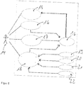
- the application offers the user 14 four different menu items: Under menu item 15, the user 14 can transmit the stored operating data to the backend, wherein the data from the smartphone own memory 16 come. Under menu item 16, the user can start the recording of GPS data, which are then assigned to the stored operating data on the timeline accordingly. Menu item 17 provides the central input option with which the start command for freezing the operating data from the rolling memory and the recording of the operating data in the linear memory is started. The operating data is transferred to the memory 16. Under menu item 18 the user accomplishes the recording of additional data. He can make a text input via a text field 19 presented to him. In addition, he can cause a recording with a camera 20, a microphone 21 or a Videocro 22. The data recorded in each case are also transferred to the memory 16.
Landscapes
- Physics & Mathematics (AREA)
- General Physics & Mathematics (AREA)
- Time Recorders, Dirve Recorders, Access Control (AREA)
- Traffic Control Systems (AREA)
Abstract
Description
- Die Erfindung betrifft ein Verfahren und ein System zur Aufzeichnung von Betriebsdaten ("Data Logging") in einem sich im Betrieb befindlichen Kraftfahrzeug, wobei die aufzuzeichnenden Betriebsdaten mittels am Kraftfahrzeug befindlicher Sensoren aufgenommen werden und die Sensoren oder deren Auswertemodule über eine gemeinsame serielle Datenleitung (Fahrzeugbus), insbesondere über einen CAN (Controller Area Network) Bus, mit einer Speichereinheit in datenleitender Verbindung stehen. Die aufgenommenen Betriebsdaten werden dann in der Speichereinheit aufgezeichnet.
- Derartige Verfahren und entsprechende Systeme sind seit langer Zeit bekannt. Sie werden eingesetzt, um während der Fahrt eine Vielzahl von Parametern (Betriebsdaten), die den Betrieb des Kraftfahrzeugs und die Bedingungen während der Fahrt charakterisieren, zusammen mit einer Zeitachse aufzuzeichnen. Mit der Vielzahl der aufzuzeichnenden Betriebsdaten wächst jedoch auch die Komplexität der Auswertung, so dass es immer schwieriger wird, aus dem Datenstrom der Betriebsdaten die Störungen zu erkennen. Das gilt insbesondere, da bekannte Systeme während einer Testfahrt das komplette Datenaufkommen auf dem Fahrzeugbus kontinuierlich aufzeichnen. Anomalien während der Testfahrt werden dann von einer Person schriftlich fixiert. Im Anschluss an die Testfahrt erfolgt dann eine zeitaufwendige Nachbereitung und Auswertung anhand der aufgezeichneten Daten in Verbindung mit den Notizen. Dabei werden aus der Masse der aufgezeichneten Daten einzelne Fragmente extrahiert, die mit den jeweiligen manuellen Aufzeichnungen zeitlich korrelieren sollen. Diese Art der Auswertung birgt ein hohes Fehlerpotential wegen der schwierigen Synchronisierung der Fragmente aus den CAN Daten und der manuellen Aufzeichnungen.
- Außerdem sind Systeme zur Unfalldatenspeicherung bekannt. Stellvertretend wird auf die
DE 10 2013 014 879 A1 hingewiesen. Diese Systeme funktionieren im Prinzip wie die Black-Box und der Voice Recorder in Flugzeugen. Sie zeichnen bestimmte Betriebsdaten in einem rollierenden Ringspeicher auf. Wenn es zum Unfall kommt, dient dieses Ereignis als Trigger-Signal, woraufhin der Speicherinhalt des Ringspeichers in einen dauerhaften Speicher übertragen wird und dort zur Auslese zur Verfügung steht. Ähnliche Systeme sind in derDE 10 2008 047 727 A1 und derDE 10 2013 225 338 A1 bekannt. - Aufgabe der Erfindung ist es nunmehr, ein Verfahren respektive ein System zur Aufzeichnung von Betriebsdaten in Kraftfahrzeugen vorzuschlagen, das sich einfach und mit kostengünstigen Mitteln umsetzen lässt und das eine komfortable Auswertung anhand der aufgenommenen Betriebsdaten und eine genaue Fehlerdiagnose gewährleistet.
- Diese Aufgabe wird durch das Verfahren nach Anspruch 1 und das System nach Anspruch 8 gelöst. Bevorzugte Ausgestaltungen ergeben sich aus den jeweiligen Unteransprüchen.
- Entsprechend der Ansprüche liegt die grundlegende Idee der erfindungsgemäßen Lösung zusammengefasst zunächst darin, die Betriebsdaten des Kraftfahrzeugs während des Betriebs nur innerhalb eines definierten Zeitintervalls zusammen mit der Zeitachse aufzuzeichnen und abzuspeichern, wobei dieses Zeitintervall durch den Zeitpunkt des Auftretens eines Ereignisses - in Form des Auftretens eines Störund/oder Fehlverhaltens - derart festgelegt wird, so dass das Ereignis innerhalb des aufgezeichneten Zeitintervalls zu liegen kommt. Dabei setzt sich das Zeitintervall zusammen aus einem ersten Teilintervall ΔT1, das vor dem Ereignis liegt, und einem zweiten Teilintervall ΔT2, das nach dem Ereignis liegt.
- Erfindungsgemäß wird das vor dem Ereignis liegende erste Teilintervall mit einem Ringspeicher aufgenommen, dessen Inhalt sich wie bei einem Stimmenrecorder ständig rollierend überschreibt. In dem Ringspeicher werden somit die Betriebsdaten fortlaufend beispielsweise für die letzten Minuten oder Sekunden in einer Endlosschleife aufgezeichnet. Die Datenaufnahme in den Ringspeicher wird zu Beginn einer Testfahrt gestartet. Wenn dann das Ereignis eintritt, wird der Inhalt des Ringspeichers quasi "eingefroren", so dass das Datenaufkommen in dem ersten Teilintervall vor Eintritt des Ereignisses zusammen mit der Zeitachse gespeichert ist. Die Länge des ersten Teilintervalls wird dementsprechend durch den Speicherinhalt des Ringspeichers definiert. Erfindungsgemäß werden nach Eintritt des Ereignisses die Betriebsdaten noch innerhalb des zweiten Teilintervalls "linear" auf der Zeitachse aufgenommen. Die im zweiten Teilintervall aufgenommenen Betriebsdaten werde dann an die des ersten Teilintervalls zeitlich angehängt.
- Anspruchsgemäß werden die Betriebsdaten somit innerhalb des gesamten Zeitintervalls entlang der Zeitachse aufgezeichnet, wobei die Länge des Zeitintervalls über die Längen der beiden Teilintervalle vorgebbar ist. Der bezüglich des Ereignisses in der Vergangenheit liegende Anfangszeitpunkt des Zeitintervalls wird durch den Speicherinhalt der als Ringspeicher ausgebildeten ersten Speichereinheit definiert, in die die Betriebsdaten während des Betriebes kontinuierlich rollierend aufzeichnet werden. Der Endzeitpunkt des Zeitintervalls wird dann über das zweite Teilintervall definiert, dessen Länge durch eine Benutzervorgabe voreingestellt wird.
- Dabei wird das Zeitintervall während der rollierenden Aufzeichnung in den Ringspeicher mit einem Startbefehl an einem Fixpunkt, der mit dem Zeitpunkt des Auftretens des Ereignisses korreliert, fixiert. Mit dem Startbefehl wird der aktuelle Inhalt des Ringspeichers "eingefroren", insbesondere in einen separaten Speicher kopiert, und die weiteren vom Fixpunkt bis zum Endzeitpunkt aufgezeichneten Betriebsdaten werden als zeitlich lineare Datenfolge an die aus dem Ringspeicher stammenden Betriebsdaten angehängt.
- Um das Zeitintervall flexibel einstellen zu können, ist es vorteilhaft, die Speicherkapazität des Ringspeichers und damit die Länge des ersten Teilintervalls durch eine Benutzervorgabe voreinzustellen. Dabei kann sich die Vorgabe der Speicherkapazität an dem zu erwartenden Ereignis und an dessen Vorgeschichte ausrichten. Im Normalfall wird es ausreichen, die Speicherkapazität so einzustellen, dass die Betriebsdaten über einige Minuten aufgenommen werden, bevor sie rollierend überschrieben werden.
- Um plötzlich eintretende Ereignisse nachträglich besser analysieren zu können, ist es vorteilhaft, neben der zeitlichen Länge der Teilintervalle auch die zeitliche Auflösung einstellen zu können. Bei höherer Auflösung werden mehr Betriebsdaten pro Zeiteinheit von den Sensoren aufgenommen und abgespeichert. Auch die Vorgabe einer geringeren Auflösung kann Vorteile haben, um Langzeiteffekte im Zeitraffer untersuchen zu können.
- Zur Verbesserung des Bedienkomforts ist es von Vorteil, das System aus verschiedenen untereinander in datenleitender Verbindung stehenden Komponenten zusammenzusetzen. Dabei kann das automotive CAN-Bus Aufzeichnungsgerät ("Tracker") als eine eigebettete ("embedded") Komponente ausgestaltet sein, die eine datenleitende Anbindung an eine auf einem Smartphone laufende Applikation ("App") hat. Über die Applikation können die Funktionen des Trackers eingestellt und die aufgenommenen Betriebsdaten verarbeitet werden. Insbesondere kann über die App auf dem Smartphone der Startbefehl per "one-Klick" oder per Sprachbefehl generiert und über die Funkverbindung von dem Smartphone an den Tracker geschickt werden. Zudem können die vom Tracker aufgenommenen Betriebsdaten über die Applikation an einen zentralen Hintergrundrechner ("Backend") übertragen werden. Die Datenübertragung zwischen dem Tracker und dem Smartphone sowie zwischen dem Smartphone und dem Backend findet vorteilhafterweise jeweils über eine Funkverbindung, insbesondere über eine Fernfunkverbindung LTE, UMTS oder eine Nahfunkverbindung wie WLAN oder Bluetooth, statt.
- Mit einem solchen System kann die Kommunikation auf dem CAN Bus in relevanten Zeitabschnitten aufgezeichnet und zusätzlich mit Sekundärinformation angereichert werden. Alle Daten werden zeitnah an das Backend übermittelt und stehen dort zentral zur analysierenden Aufwertung zur Verfügung. Wichtige Fahrzeugbus-Daten können in einem über die App parametrierbaren Zeitabschnitt aufgezeichnet werden. Diese entlang der Zeitachse aufgezeichneten CAN-Daten können vom Anwender zusätzlich mit Sekundärinformation, wie Fotos, Videos, Audio-Dateien und/oder Texteingaben, über das Smartphone verknüpft werden. Zudem können die GPS- und Zeitdaten des Ereignisses sowie GPS- und Zeitdaten der Testfahrt zu bestimmten Zeitpunkten entlang der Zeitachste gespeichert werden. Insgesamt erbringt das erfindungsgemäße System erhebliche Zeiteinsparungen bei der Auswertung
- Diese Art des erfindungsgemäßen Aufzeichnens der Betriebsdaten in Kombination mit Positions- und Zeitangaben sowie speziellen Benutzereingaben in Form von Audio/Video- und Texteingaben erleichtert und beschleunigt die Auswertung der Betriebsdaten im Backend und ermöglicht eine genaue Fehleranalyse. Mit Einsatz der Erfindung ist es nun nicht mehr notwendig, die enormen Datenmengen der CAN-Daten mit den GPS-Daten und Sprachaufnahmen nach der Testfahrt wie vormals zu fragmentieren und anschließend zu verknüpfen. Der erfindungsgemäße "Device Analytics Tracker" gewährleistet eine Arbeits-, Zeit- und Resourcenersparnis.
- Damit ist der erfindungsgemäße "Device Analytics Tracker" ein System für den automotiven Sektor, das in der Lage ist, die relevanten CAN- Betriebsdaten vom CAN-Bus des Fahrzeuges "herauszufiltern". Diese Betriebsdaten können direkt mit den entsprechenden GPS- und Zeitdaten sowie den Sekundärinformationen des Anwenders verknüpft und abgespeichert werden. Dabei können die GPS-Daten auch dann gespeichert werden, wenn keine CAN-Bus Aufnahme stattfindet, um später die komplette Streckenroute der Testfahrt nachvollziehen zu können.
- Sobald ein Ereignis in Form einer Störung oder eines Fehler auftritt, wird die CAN-Bus Aufzeichnung erfindungsgemäß automatisch oder durch eine Person im Fahrzeug per "One-Klick" oder Sprachkommando als Startbefehl gestartet und damit der Fixpunkt festgelegt. Die zurückliegenden CAN-Daten sind im Ringpuffer über einen gewissen Zeitraum zwischengespeichert und bilden das erste Teilintervall. Beim Starten der Aufzeichnung wird also zunächst der Inhalt des Ringspeichers gespeichert. Dabei kann die Vorlaufzeit des Ringspeichers und/oder die Nachlaufzeit der linearen Datenaufnahme, die das zweite Teilintervall bildet, über das Smartphone parametriesiert werden. Die lineare Datenaufnahme erfolgt als Echtzeitaufnahme der über den CAN-Bus ausgetauschten Daten. Alle Daten können später direkt an das Backend gesendet werden, wobei es vorteilhaft ist, für das Backend eine Cloudlösung vorzusehen. Die Daten im Backend können zu einem späteren Zeitpunkt ausgewertet und analysiert werden. Zudem besteht die Möglichkeit, die Testfahren zu visualisieren und die Ereignissdaten zum Download bereit zu stellen.
- Die Erfindung wird nachfolgend anhand der Figuren näher beschrieben. Es zeigen:
- Figur 1
- das erfindungsgemäße System und
- Figur 2
- die Funktionsweise der auf dem Smartphone laufenden Applikation.
- In
Figur 1 sind die Komponenten des erfindungsgemäßen Systems dargestellt. In einem Kraftfahrzeug 1 ist ein CAN-Datenlogger 2 ("Tracker") eingebaut und an den CAN Bus des Kraftfahrzeugs 1 angeschlossen. Zur Aufnahme der relevanten Betriebsdaten sind im und/oder am Kraftfahrzeug 1 entsprechende Sensoren angebracht, die unmittelbar oder über Auswertemodule an den CAN Bus angeschlossen sind. Der Begriff "Sensor" ist hier in großer Allgemeinheit gebraucht und umfasst alle Mittel, mit denen sich Betriebsdaten in Form physikalischer Größen aufnehmen lassen, die im Zusammenhang mit dem Kraftfahrzeug, mit der Fahrt oder mit der Umgebung stehen. Im Kraftfahrzeug 1 ist zudem eine Speichereinheit vorgesehen, mit der die Betriebsdaten aufgezeichnet werden. Auch das Merkmal "Kraftfahrzeug" ist in großer Allgemeinheit gebraucht und umfasst alle Fahrzeuge, die sich auf dem Land, in der Luft und auf dem Wasser bewegen. - Erfindungsgemäß ist die Speichereinheit als ein Ringspeicher oder Ringpuffer ausgebildet, der die Betriebsdaten während des Betriebes kontinuierlich und zusammen mit der Zeitachse aufzeichnet und die aufgezeichneten Betriebsdaten "rollierend" bei Erreichen der Speicherkapazität am Anfang beginnend wieder überschreibt. Die Speicherkapazität des Ringspeichers - und damit die Länge des aufzuzeichnenden ersten Teilintervalls- kann durch eine Benutzervorgabe voreingestellt werden.
- Zudem umfasst das System ein Smartphone 3, auf dem eine Applikation zur Handhabung des Systems läuft. Das Menü auf dem Smartphone 3 ist in zwei Zuständen gezeigt. Während der die Bedienoberfläche 23 die Auswahl bestimmter Zusatzdaten ermöglicht, präsentiert die Bedienoberfläche 24 einen markanten Startknopf 25, mit em die Eingabe des Stratbefehls ermöglicht wird. Zwischen dem Kraftfahrzeug und dem Smartphone ist eine Nahfunkverbindung 4 vorgesehen, über welche die Betriebsdaten vom Kraftfahrzeug 1 zum Smartphone 3 und Steuerbefehle vom Smartphone 3 zum Kraftfahrzeug 1 übermittelt werden. Die Nahfunkverbindung arbeitet über Bluetooth oder WLAN. Die oben genannte Speichereinheit in Form des Ringspeichers kann auch im Smartphone 3 implementiert sein, so dass die Betriebsdaten im Kraftfahrzeug aufgenommen und über die Nahfunkverbindung 4 an das Smartphone zur Abspeicherung übermittelt werden.
- Die auf dem Smartphone 3 laufende Applikation ermöglicht die Vorgabe des Startbefehls durch One-Klick. Zudem können während der Aufzeichnung der Betriebsdaten im Ringspeicher (erstes Teilintervall) und im linearen Speicher (zweites Teilintervall) über die Applikation Bilddaten, Videodaten, Sprachdaten und Textdaten erstellt und den Betriebsdaten in zeitlicher Synchronisation zugeordnet werden. Beim Speichern der Eingaben werden diese zusätzlichen Daten mit den aufgenommenen CAN-Frames verknüpft. Insbesondere kann der Nutzer 5 über die Audioverbindung 6 einen Sprachbefehl "Fehler auf nasser Fahrbahn" eingeben.
- Eine weitere Komponente des erfindungsgemäßen Systems ist das Backendsystem in der Datencloud 7, das über eine Funkverbindung 8 zugänglich ist. Hier stehen große Rechner- und Speicherkapazitäten zur Verfügung, so dass eine genaue Analyse der um das Ereignis herum aufgenommenen Betriebsdaten möglich ist. Dazu ist im Backendsystem ein entsprechendes Modul 9 vorgesehen. Zudem können vom Backendsystem Schnittstellen 10 zu allen möglichen Systemen zur Verfügung gestellt werden. Auch Funktionen 11 zur Konvertierung von Sprache in Text und Schnittstellen 12 zu "BigData" können vorgesehen sein. Beliebige weitere Module 13 sind möglich. Mit der Datenübertragung an das Backend hat der Nutzer die Möglichkeit, alle gespeicherten Daten des Systems über das Internet an das Backend zu senden. Nach erfolgreichem Senden können die Daten vom CAN-Bus Tracker gelöscht werden.
- In
Figur 2 ist die Struktur der auf dem Smartphone laufenden Applikation gezeigt. Zunächst bietet die Applikation dem Nutzer 14 vier verschiedene Menüpunkte: Unter Menüpunkt 15 kann der Nutzer 14 die gespeicherten Betriebsdaten an das Backend übertragen, wobei die Daten aus dem Smartphone eigenen Speicher 16 stammen. Unter Menüpunkt 16 kann der Nutzer die Aufzeichnung von GPS Daten starten, die dann den gespeicherten Betriebsdaten auf dem Zeitstrahl entsprechend zugeordnet werden. Menüpunkt 17 bietet die zentrale Eingabemöglichkeit, mit der der Startbefehl zum Einfrieren der Betriebsdaten aus dem rollierenden Speicher und die Aufnahme der Betriebsdaten in den linearen Speicher gestartet wird. Die Betriebsdaten wereden in den Speicher 16 transferriert. Unter Menüpunkt 18 bewerkstelligt der Nutzer die Aufnahme zusätzlicher daten. Über ein ihm dargebotenes Textfeld 19 kann er eine Texteingabe machen. Zudem kann er eine Aufnahme mit einer Fotokamera 20, einem Mikrofon 21 oder einer Videokammera 22 veranlassen. Die jeweils aufgenommen Daten werden ebenfalls in den Speicher 16 transferriert.
Claims (9)
- Verfahren zur Aufzeichnung von Betriebsdaten in einem im Betrieb befindlichen Kraftfahrzeug (1), wobei die aufzuzeichnenden Betriebsdaten mittels am Kraftfahrzeug (1) befindlicher Sensoren aufgenommen werden, wobei die Sensoren oder deren Auswertemodule über eine gemeinsame Datenleitung, insbesondere einen CAN Bus, mit einer Speichereinheit (2) in datenleitender Verbindung stehen und wobei die Betriebsdaten in der Speichereinheit (2) aufgezeichnet werden,
dadurch gekennzeichnet
dass die Betriebsdaten innerhalb eines Zeitintervalls vorgebbarer Länge aufgezeichnet werden,
wobei der Anfangszeitpunkt des Zeitintervalls durch den Speicherinhalt der als Ringspeicher ausgebildeten Speichereinheit definiert wird,
wobei der Ringspeicher die Betriebsdaten während des Betriebes kontinuierlich aufzeichnet und bei Erreichen seiner Speicherkapazität am Anfang beginnend überschreibt,
wobei der Endzeitpunkt des Zeitintervalls durch eine Benutzervorgabe definiert wird,
wobei mit einem Startbefehl das Zeitintervall an einem zeitlichen Fixpunkt fixiert wird,
wobei das Zeitintervall ein erstes Teilintervall, das vor dem Fixpunkt liegt, und ein zweites Teilintervall, das nach dem Fixpunkt liegt, aufweist, wobei mit dem Startbefehl der aktuelle Inhalt des Ringspeichers als erstes Teilintervall in einen Speicher kopiert wird,
wobei die vom Fixpunkt bis zum Endzeitpunkt aufgezeichneten Betriebsdaten als zweites Teilintervall in einen Speicher kopiert werden und wobei die Betriebsdaten aus den beiden Teilintervallen zeitlich hintereinander gekoppelt werden. - Verfahren nach Anspruch 1 oder 2,
dadurch gekennzeichnet,
dass die Speicherkapazität des Ringspeichers und damit die Länge des zweiten Teilintervalls durch eine Benutzervorgabe voreingestellt wird. - Verfahren nach einem der vorherigen Ansprüche,
dadurch gekennzeichnet,
dass die zeitliche Auflösung der Aufnahme der Betriebsdaten durch eine Benutzervorgabe voreingestellt wird. - Verfahren nach einem der vorherigen Ansprüche,
dadurch gekennzeichnet,
dass die innerhalb des Zeitintervalls aufgezeichneten Betriebsdaten über eine Funkverbindung (4), insbesondere über WLAN oder Bluetooth, an ein Smartphone (3) gesendet und dort zur weiteren Verarbeitung durch eine Applikation gespeichert werden. - Verfahren nach Anspruch 5,
dadurch gekennzeichnet,
dass der Startbefehl von der Applikation auf dem Smartphone (3) generiert und über die Funkverbindung (4) an das System geschickt wird. - Verfahren nach einem der vorherigen Ansprüche,
dadurch gekennzeichnet,
dass mittels des Smartphones (3) Zusatzdaten in Form von Bilddaten, Textdaten oder Audiodaten zu bestimmten Zeitpunkten aufgenommen und den aufgezeichneten Betriebsdaten zu entsprechenden Zeitpunkten zugeordnet werden. - Verfahren nach Anspruch 6,
dadurch gekennzeichnet,
dass die Betriebsdaten gegebenenfalls mit den zugeordneten Zusatzdaten mittels der Applikation von dem Smartphone über eine Funkverbindung (8), insbesondere über WLAN oder Bluetooth, zur Auswertung an ein Backendsystem (7) geschickt werden. - System zur Durchführung des Verfahrens nach einem der vorherigen Ansprüche, aufweisend,
durch gekennzeichnet
einen im Kraftfahrzeug eingebauten Datenlogger (2), der an dem Fahrzeug Datenbus angeschlossen ist und die Aufzeichnung der von den Sensoren gewonnenen Betriebsdaten bewerkstelligt,
ein Smartphone (3) mit einer darauf laufenden Applikation zur Handhabung des Systems, wobei das Smartphone (3) über eine Nahfunkverbindung (4) mit dem Datenlogger (2) in datenleitender Verbindung steht,
ein Backendsystem (7) zur Auswertung der aufgenommen Betriebsdaten, wobei das das Smartphone (3) über eine Funkverbindung (8) mit dem Backendsystem (7) in datenleitender Verbindung steht, und
eine Speichereinheit umfassend einen Ringspeicher zur rollierenden Aufzeichnung der Betriebsdaten in einem ersten zeitlichen Teilintervall und einen Speicher zur linearen Aufzeichnung der Betriebsdaten in einem zweiten zeitlichen Teilintervall. - System nach Anspruch 8,
dadurch gekennzeichnet,
dass die Speichereinheit Teil des Datenloggers ist.
Applications Claiming Priority (1)
| Application Number | Priority Date | Filing Date | Title |
|---|---|---|---|
| DE102016102851 | 2016-02-18 |
Publications (2)
| Publication Number | Publication Date |
|---|---|
| EP3208775A1 true EP3208775A1 (de) | 2017-08-23 |
| EP3208775B1 EP3208775B1 (de) | 2024-03-06 |
Family
ID=58094137
Family Applications (1)
| Application Number | Title | Priority Date | Filing Date |
|---|---|---|---|
| EP17153965.3A Active EP3208775B1 (de) | 2016-02-18 | 2017-01-31 | Aufnahme von betriebsdaten in einem kraftfahrzeug |
Country Status (1)
| Country | Link |
|---|---|
| EP (1) | EP3208775B1 (de) |
Cited By (6)
| Publication number | Priority date | Publication date | Assignee | Title |
|---|---|---|---|---|
| WO2019081236A1 (de) * | 2017-10-26 | 2019-05-02 | Robert Bosch Gmbh | Vorrichtung und verfahren zur dokumentation von technischen problemen in einem kraftfahrzeug |
| DE102018207339A1 (de) * | 2018-05-09 | 2019-11-14 | Volkswagen Aktiengesellschaft | Verfahren, Vorrichtung und computerlesbares Speichermedium mit Instruktionen zum Überwachen und Validieren von Betriebsdaten in der Aktuatorik eines autonomen Kraftfahrzeugs |
| WO2020035639A1 (fr) * | 2018-08-17 | 2020-02-20 | Psa Automobiles Sa | Procede de surveillance d'un systeme de motorisation de vehicule |
| CN112948121A (zh) * | 2021-03-19 | 2021-06-11 | 深圳市泰祺科技有限公司 | 一种微控制云端数据传输方法及系统 |
| WO2023213477A1 (de) * | 2022-05-05 | 2023-11-09 | Bayerische Motoren Werke Aktiengesellschaft | Computer-implementiertes verfahren und vorrichtung zur auslegung einer datensammelkampagne für ein kraftfahrzeug |
| EP4552467A1 (de) * | 2023-11-10 | 2025-05-14 | Lemken GmbH & Co KG | Landwirtschaftliche arbeitsmaschine |
Citations (6)
| Publication number | Priority date | Publication date | Assignee | Title |
|---|---|---|---|---|
| US20050240343A1 (en) * | 2004-04-23 | 2005-10-27 | Schmidt Peter E Ii | Portable wireless device utilization for telematics purposes |
| DE102008047727A1 (de) | 2008-09-18 | 2010-03-25 | Fsd Fahrzeugsystemdaten Gmbh | Datenschreiber, Fahrerassistenzsystem und Verfahren zur Identifikation von kritischen Fahrsituationen |
| DE102013000686A1 (de) * | 2013-01-11 | 2014-07-17 | Iav Gmbh Ingenieurgesellschaft Auto Und Verkehr | Verfahren und Vorrichtung zur Aufnahme von Daten |
| DE102013014879A1 (de) | 2013-09-06 | 2015-03-12 | Audi Ag | Kraftfahrzeug mit einem Unfalldatenspeicher |
| DE102013225338A1 (de) | 2013-12-10 | 2015-06-11 | Conti Temic Microelectronic Gmbh | Verfahren und Vorrichtung zur Aufzeichnung von Bilddaten aus einer Fahrzeugumgebung |
| US20150187146A1 (en) * | 2012-05-09 | 2015-07-02 | Innova Electronics, Inc. | Smart phone app-based remote vehicle diagnostic system and method |
-
2017
- 2017-01-31 EP EP17153965.3A patent/EP3208775B1/de active Active
Patent Citations (6)
| Publication number | Priority date | Publication date | Assignee | Title |
|---|---|---|---|---|
| US20050240343A1 (en) * | 2004-04-23 | 2005-10-27 | Schmidt Peter E Ii | Portable wireless device utilization for telematics purposes |
| DE102008047727A1 (de) | 2008-09-18 | 2010-03-25 | Fsd Fahrzeugsystemdaten Gmbh | Datenschreiber, Fahrerassistenzsystem und Verfahren zur Identifikation von kritischen Fahrsituationen |
| US20150187146A1 (en) * | 2012-05-09 | 2015-07-02 | Innova Electronics, Inc. | Smart phone app-based remote vehicle diagnostic system and method |
| DE102013000686A1 (de) * | 2013-01-11 | 2014-07-17 | Iav Gmbh Ingenieurgesellschaft Auto Und Verkehr | Verfahren und Vorrichtung zur Aufnahme von Daten |
| DE102013014879A1 (de) | 2013-09-06 | 2015-03-12 | Audi Ag | Kraftfahrzeug mit einem Unfalldatenspeicher |
| DE102013225338A1 (de) | 2013-12-10 | 2015-06-11 | Conti Temic Microelectronic Gmbh | Verfahren und Vorrichtung zur Aufzeichnung von Bilddaten aus einer Fahrzeugumgebung |
Cited By (12)
| Publication number | Priority date | Publication date | Assignee | Title |
|---|---|---|---|---|
| WO2019081236A1 (de) * | 2017-10-26 | 2019-05-02 | Robert Bosch Gmbh | Vorrichtung und verfahren zur dokumentation von technischen problemen in einem kraftfahrzeug |
| DE102018207339A1 (de) * | 2018-05-09 | 2019-11-14 | Volkswagen Aktiengesellschaft | Verfahren, Vorrichtung und computerlesbares Speichermedium mit Instruktionen zum Überwachen und Validieren von Betriebsdaten in der Aktuatorik eines autonomen Kraftfahrzeugs |
| WO2019215017A1 (de) | 2018-05-09 | 2019-11-14 | Volkswagen Aktiengesellschaft | Verfahren, vorrichtung und computerlesbares speichermedium mit instruktionen zum überwachen und validieren von betriebsdaten in der aktuatorik eines autonomen kraftfahrzeugs |
| WO2020035639A1 (fr) * | 2018-08-17 | 2020-02-20 | Psa Automobiles Sa | Procede de surveillance d'un systeme de motorisation de vehicule |
| FR3085057A1 (fr) * | 2018-08-17 | 2020-02-21 | Psa Automobiles Sa | Procede de surveillance d’un systeme de motorisation de vehicule |
| CN112567123A (zh) * | 2018-08-17 | 2021-03-26 | 标致雪铁龙汽车股份有限公司 | 车辆机动化系统的监控方法 |
| CN112567123B (zh) * | 2018-08-17 | 2022-12-23 | 标致雪铁龙汽车股份有限公司 | 车辆机动化系统的监控方法 |
| CN112948121A (zh) * | 2021-03-19 | 2021-06-11 | 深圳市泰祺科技有限公司 | 一种微控制云端数据传输方法及系统 |
| CN112948121B (zh) * | 2021-03-19 | 2023-09-01 | 深圳市泰祺科技有限公司 | 一种微控制云端数据传输方法及系统 |
| WO2023213477A1 (de) * | 2022-05-05 | 2023-11-09 | Bayerische Motoren Werke Aktiengesellschaft | Computer-implementiertes verfahren und vorrichtung zur auslegung einer datensammelkampagne für ein kraftfahrzeug |
| EP4552467A1 (de) * | 2023-11-10 | 2025-05-14 | Lemken GmbH & Co KG | Landwirtschaftliche arbeitsmaschine |
| DE102023131365A1 (de) * | 2023-11-10 | 2025-05-15 | Lemken Gmbh & Co. Kg | Landwirtschaftliche Arbeitsmaschine |
Also Published As
| Publication number | Publication date |
|---|---|
| EP3208775B1 (de) | 2024-03-06 |
Similar Documents
| Publication | Publication Date | Title |
|---|---|---|
| EP3208775B1 (de) | Aufnahme von betriebsdaten in einem kraftfahrzeug | |
| EP2912544B1 (de) | Vorrichtung und verfahren zur bereitstellung multimedialer daten in einem kraftfahrzeug | |
| DE102011017590A1 (de) | Eigebettete Fahrzeugdatenaufzeichnungs-Werkzeuge für Fahrzeugservice | |
| DE102012019185B4 (de) | Verfahren und System zum Ermitteln einer Mobilfunknetzqualität und Laden von Mobilfunkdaten | |
| DE102018127443A1 (de) | Bordeigenes System zum Kommunizieren mit den Insassen | |
| EP3831035B1 (de) | Verfahren und zwischenspeichereinrichtung für messdaten von fahrzeugen | |
| DE102022209097A1 (de) | Intelligente Telematikdatensynchronisation | |
| DE102019132876A1 (de) | Verfahren und system zum bereitstellen vollständiger ereignisdaten aus querverwiesenen datenspeichern | |
| DE102015226147B4 (de) | Verfahren, Prozessorvorrichtung, Kraftfahrzeug mit einer solchen Prozessorvorrichtung und Telematiksystem für die automatische Konfiguration telematischer Datenübermittlungen des Kraftfahrzeugs | |
| EP3667568A1 (de) | Konfiguration eines steuerungssystems für ein zumindest teilautonomes kraftfahrzeug | |
| DE102018221933A1 (de) | Verteiltes Datenaustauschsystem für ein Fahrzeug | |
| DE102014007797A1 (de) | Verfahren zur Erfassung eines Betriebsgeräuschs, insbesondere eines Bremsgeräuschs, und Kraftfahrzeug | |
| DE102013204128A1 (de) | Vorrichtung, Verfahren und System zur Überwachung von Betriebsdaten eines Kraftfahrzeugs | |
| DE112015003801T5 (de) | System und verfahren zum automatischen pushen von standortspezifischem inhalt an benutzer | |
| DE102021201978A1 (de) | Sammeln von sensordaten von fahrzeugen | |
| EP3844936B1 (de) | Anfordern, analysieren und übermitteln von daten der fahrerassistenzsysteme eines fahrzeugs an einen externen nutzer | |
| DE102013000686B4 (de) | Verfahren und Vorrichtung zur Aufnahme von Daten | |
| DE102014212781A1 (de) | Verfahren zum Ermitteln und Bereitstellen einer Landmarke zur Positionsbestimmung für ein Fahrzeug | |
| DE102013216688A1 (de) | Verfahren und Vorrichtung zur Durchführung einer Referenzmessung an einem Sensor einer Brennkraftmaschine | |
| DE102015200269A1 (de) | Verfahren und System für die Erfassung von Fahrzeugereignissen | |
| DE102019102851A1 (de) | Verfahren zur Fernanalyse eines Funktionsfehlers eines Fortbewegungsmittels, elektronisches Anwenderendgerät, Fortbewegungsmittel, Backend-Server und System | |
| DE102022205885A1 (de) | Verfahren, Computerprogramm und Vorrichtung zur Verarbeitung von Zeitreihendaten mit einem künstlichen Neuronalen Netzwerk | |
| DE10207222A1 (de) | Verfahren und Vorrichtung zum Prozessdatenerfassen | |
| DE102005025265B4 (de) | Verfahren und Vorrichtung zum Erfassen und Auswerten von Daten von zumindest einer Einheit in einem Kraftfahrzeug | |
| DE102017209195A1 (de) | Verfahren zur Dokumentation eines Fahrbetriebs eines Kraftfahrzeugs |
Legal Events
| Date | Code | Title | Description |
|---|---|---|---|
| PUAI | Public reference made under article 153(3) epc to a published international application that has entered the european phase |
Free format text: ORIGINAL CODE: 0009012 |
|
| STAA | Information on the status of an ep patent application or granted ep patent |
Free format text: STATUS: THE APPLICATION HAS BEEN PUBLISHED |
|
| AK | Designated contracting states |
Kind code of ref document: A1 Designated state(s): AL AT BE BG CH CY CZ DE DK EE ES FI FR GB GR HR HU IE IS IT LI LT LU LV MC MK MT NL NO PL PT RO RS SE SI SK SM TR |
|
| AX | Request for extension of the european patent |
Extension state: BA ME |
|
| STAA | Information on the status of an ep patent application or granted ep patent |
Free format text: STATUS: REQUEST FOR EXAMINATION WAS MADE |
|
| 17P | Request for examination filed |
Effective date: 20180223 |
|
| RBV | Designated contracting states (corrected) |
Designated state(s): AL AT BE BG CH CY CZ DE DK EE ES FI FR GB GR HR HU IE IS IT LI LT LU LV MC MK MT NL NO PL PT RO RS SE SI SK SM TR |
|
| STAA | Information on the status of an ep patent application or granted ep patent |
Free format text: STATUS: EXAMINATION IS IN PROGRESS |
|
| 17Q | First examination report despatched |
Effective date: 20200219 |
|
| RIC1 | Information provided on ipc code assigned before grant |
Ipc: G07C 5/00 20060101ALI20230831BHEP Ipc: G07C 5/08 20060101AFI20230831BHEP |
|
| GRAP | Despatch of communication of intention to grant a patent |
Free format text: ORIGINAL CODE: EPIDOSNIGR1 |
|
| STAA | Information on the status of an ep patent application or granted ep patent |
Free format text: STATUS: GRANT OF PATENT IS INTENDED |
|
| INTG | Intention to grant announced |
Effective date: 20231019 |
|
| GRAS | Grant fee paid |
Free format text: ORIGINAL CODE: EPIDOSNIGR3 |
|
| GRAA | (expected) grant |
Free format text: ORIGINAL CODE: 0009210 |
|
| STAA | Information on the status of an ep patent application or granted ep patent |
Free format text: STATUS: THE PATENT HAS BEEN GRANTED |
|
| AK | Designated contracting states |
Kind code of ref document: B1 Designated state(s): AL AT BE BG CH CY CZ DE DK EE ES FI FR GB GR HR HU IE IS IT LI LT LU LV MC MK MT NL NO PL PT RO RS SE SI SK SM TR |
|
| REG | Reference to a national code |
Ref country code: GB Ref legal event code: FG4D Free format text: NOT ENGLISH |
|
| REG | Reference to a national code |
Ref country code: CH Ref legal event code: EP |
|
| REG | Reference to a national code |
Ref country code: IE Ref legal event code: FG4D Free format text: LANGUAGE OF EP DOCUMENT: GERMAN |
|
| REG | Reference to a national code |
Ref country code: DE Ref legal event code: R096 Ref document number: 502017015888 Country of ref document: DE |
|
| REG | Reference to a national code |
Ref country code: LT Ref legal event code: MG9D |
|
| PG25 | Lapsed in a contracting state [announced via postgrant information from national office to epo] |
Ref country code: LT Free format text: LAPSE BECAUSE OF FAILURE TO SUBMIT A TRANSLATION OF THE DESCRIPTION OR TO PAY THE FEE WITHIN THE PRESCRIBED TIME-LIMIT Effective date: 20240306 |
|
| REG | Reference to a national code |
Ref country code: NL Ref legal event code: MP Effective date: 20240306 |
|
| PG25 | Lapsed in a contracting state [announced via postgrant information from national office to epo] |
Ref country code: GR Free format text: LAPSE BECAUSE OF FAILURE TO SUBMIT A TRANSLATION OF THE DESCRIPTION OR TO PAY THE FEE WITHIN THE PRESCRIBED TIME-LIMIT Effective date: 20240607 |
|
| PG25 | Lapsed in a contracting state [announced via postgrant information from national office to epo] |
Ref country code: RS Free format text: LAPSE BECAUSE OF FAILURE TO SUBMIT A TRANSLATION OF THE DESCRIPTION OR TO PAY THE FEE WITHIN THE PRESCRIBED TIME-LIMIT Effective date: 20240606 Ref country code: HR Free format text: LAPSE BECAUSE OF FAILURE TO SUBMIT A TRANSLATION OF THE DESCRIPTION OR TO PAY THE FEE WITHIN THE PRESCRIBED TIME-LIMIT Effective date: 20240306 |
|
| PG25 | Lapsed in a contracting state [announced via postgrant information from national office to epo] |
Ref country code: ES Free format text: LAPSE BECAUSE OF FAILURE TO SUBMIT A TRANSLATION OF THE DESCRIPTION OR TO PAY THE FEE WITHIN THE PRESCRIBED TIME-LIMIT Effective date: 20240306 |
|
| PG25 | Lapsed in a contracting state [announced via postgrant information from national office to epo] |
Ref country code: RS Free format text: LAPSE BECAUSE OF FAILURE TO SUBMIT A TRANSLATION OF THE DESCRIPTION OR TO PAY THE FEE WITHIN THE PRESCRIBED TIME-LIMIT Effective date: 20240606 Ref country code: NO Free format text: LAPSE BECAUSE OF FAILURE TO SUBMIT A TRANSLATION OF THE DESCRIPTION OR TO PAY THE FEE WITHIN THE PRESCRIBED TIME-LIMIT Effective date: 20240606 Ref country code: LT Free format text: LAPSE BECAUSE OF FAILURE TO SUBMIT A TRANSLATION OF THE DESCRIPTION OR TO PAY THE FEE WITHIN THE PRESCRIBED TIME-LIMIT Effective date: 20240306 Ref country code: HR Free format text: LAPSE BECAUSE OF FAILURE TO SUBMIT A TRANSLATION OF THE DESCRIPTION OR TO PAY THE FEE WITHIN THE PRESCRIBED TIME-LIMIT Effective date: 20240306 Ref country code: GR Free format text: LAPSE BECAUSE OF FAILURE TO SUBMIT A TRANSLATION OF THE DESCRIPTION OR TO PAY THE FEE WITHIN THE PRESCRIBED TIME-LIMIT Effective date: 20240607 Ref country code: FI Free format text: LAPSE BECAUSE OF FAILURE TO SUBMIT A TRANSLATION OF THE DESCRIPTION OR TO PAY THE FEE WITHIN THE PRESCRIBED TIME-LIMIT Effective date: 20240306 Ref country code: ES Free format text: LAPSE BECAUSE OF FAILURE TO SUBMIT A TRANSLATION OF THE DESCRIPTION OR TO PAY THE FEE WITHIN THE PRESCRIBED TIME-LIMIT Effective date: 20240306 Ref country code: BG Free format text: LAPSE BECAUSE OF FAILURE TO SUBMIT A TRANSLATION OF THE DESCRIPTION OR TO PAY THE FEE WITHIN THE PRESCRIBED TIME-LIMIT Effective date: 20240306 |
|
| PG25 | Lapsed in a contracting state [announced via postgrant information from national office to epo] |
Ref country code: SE Free format text: LAPSE BECAUSE OF FAILURE TO SUBMIT A TRANSLATION OF THE DESCRIPTION OR TO PAY THE FEE WITHIN THE PRESCRIBED TIME-LIMIT Effective date: 20240306 Ref country code: LV Free format text: LAPSE BECAUSE OF FAILURE TO SUBMIT A TRANSLATION OF THE DESCRIPTION OR TO PAY THE FEE WITHIN THE PRESCRIBED TIME-LIMIT Effective date: 20240306 |
|
| PG25 | Lapsed in a contracting state [announced via postgrant information from national office to epo] |
Ref country code: NL Free format text: LAPSE BECAUSE OF FAILURE TO SUBMIT A TRANSLATION OF THE DESCRIPTION OR TO PAY THE FEE WITHIN THE PRESCRIBED TIME-LIMIT Effective date: 20240306 |
|
| PG25 | Lapsed in a contracting state [announced via postgrant information from national office to epo] |
Ref country code: NL Free format text: LAPSE BECAUSE OF FAILURE TO SUBMIT A TRANSLATION OF THE DESCRIPTION OR TO PAY THE FEE WITHIN THE PRESCRIBED TIME-LIMIT Effective date: 20240306 |
|
| PG25 | Lapsed in a contracting state [announced via postgrant information from national office to epo] |
Ref country code: IS Free format text: LAPSE BECAUSE OF FAILURE TO SUBMIT A TRANSLATION OF THE DESCRIPTION OR TO PAY THE FEE WITHIN THE PRESCRIBED TIME-LIMIT Effective date: 20240706 |
|
| PG25 | Lapsed in a contracting state [announced via postgrant information from national office to epo] |
Ref country code: PT Free format text: LAPSE BECAUSE OF FAILURE TO SUBMIT A TRANSLATION OF THE DESCRIPTION OR TO PAY THE FEE WITHIN THE PRESCRIBED TIME-LIMIT Effective date: 20240708 Ref country code: SM Free format text: LAPSE BECAUSE OF FAILURE TO SUBMIT A TRANSLATION OF THE DESCRIPTION OR TO PAY THE FEE WITHIN THE PRESCRIBED TIME-LIMIT Effective date: 20240306 |
|
| PG25 | Lapsed in a contracting state [announced via postgrant information from national office to epo] |
Ref country code: CZ Free format text: LAPSE BECAUSE OF FAILURE TO SUBMIT A TRANSLATION OF THE DESCRIPTION OR TO PAY THE FEE WITHIN THE PRESCRIBED TIME-LIMIT Effective date: 20240306 Ref country code: EE Free format text: LAPSE BECAUSE OF FAILURE TO SUBMIT A TRANSLATION OF THE DESCRIPTION OR TO PAY THE FEE WITHIN THE PRESCRIBED TIME-LIMIT Effective date: 20240306 |
|
| PG25 | Lapsed in a contracting state [announced via postgrant information from national office to epo] |
Ref country code: PL Free format text: LAPSE BECAUSE OF FAILURE TO SUBMIT A TRANSLATION OF THE DESCRIPTION OR TO PAY THE FEE WITHIN THE PRESCRIBED TIME-LIMIT Effective date: 20240306 |
|
| PG25 | Lapsed in a contracting state [announced via postgrant information from national office to epo] |
Ref country code: SK Free format text: LAPSE BECAUSE OF FAILURE TO SUBMIT A TRANSLATION OF THE DESCRIPTION OR TO PAY THE FEE WITHIN THE PRESCRIBED TIME-LIMIT Effective date: 20240306 |
|
| PG25 | Lapsed in a contracting state [announced via postgrant information from national office to epo] |
Ref country code: SM Free format text: LAPSE BECAUSE OF FAILURE TO SUBMIT A TRANSLATION OF THE DESCRIPTION OR TO PAY THE FEE WITHIN THE PRESCRIBED TIME-LIMIT Effective date: 20240306 Ref country code: SK Free format text: LAPSE BECAUSE OF FAILURE TO SUBMIT A TRANSLATION OF THE DESCRIPTION OR TO PAY THE FEE WITHIN THE PRESCRIBED TIME-LIMIT Effective date: 20240306 Ref country code: RO Free format text: LAPSE BECAUSE OF FAILURE TO SUBMIT A TRANSLATION OF THE DESCRIPTION OR TO PAY THE FEE WITHIN THE PRESCRIBED TIME-LIMIT Effective date: 20240306 Ref country code: PT Free format text: LAPSE BECAUSE OF FAILURE TO SUBMIT A TRANSLATION OF THE DESCRIPTION OR TO PAY THE FEE WITHIN THE PRESCRIBED TIME-LIMIT Effective date: 20240708 Ref country code: PL Free format text: LAPSE BECAUSE OF FAILURE TO SUBMIT A TRANSLATION OF THE DESCRIPTION OR TO PAY THE FEE WITHIN THE PRESCRIBED TIME-LIMIT Effective date: 20240306 Ref country code: IS Free format text: LAPSE BECAUSE OF FAILURE TO SUBMIT A TRANSLATION OF THE DESCRIPTION OR TO PAY THE FEE WITHIN THE PRESCRIBED TIME-LIMIT Effective date: 20240706 Ref country code: EE Free format text: LAPSE BECAUSE OF FAILURE TO SUBMIT A TRANSLATION OF THE DESCRIPTION OR TO PAY THE FEE WITHIN THE PRESCRIBED TIME-LIMIT Effective date: 20240306 Ref country code: CZ Free format text: LAPSE BECAUSE OF FAILURE TO SUBMIT A TRANSLATION OF THE DESCRIPTION OR TO PAY THE FEE WITHIN THE PRESCRIBED TIME-LIMIT Effective date: 20240306 |
|
| PG25 | Lapsed in a contracting state [announced via postgrant information from national office to epo] |
Ref country code: IT Free format text: LAPSE BECAUSE OF FAILURE TO SUBMIT A TRANSLATION OF THE DESCRIPTION OR TO PAY THE FEE WITHIN THE PRESCRIBED TIME-LIMIT Effective date: 20240306 |
|
| REG | Reference to a national code |
Ref country code: DE Ref legal event code: R097 Ref document number: 502017015888 Country of ref document: DE |
|
| PG25 | Lapsed in a contracting state [announced via postgrant information from national office to epo] |
Ref country code: IT Free format text: LAPSE BECAUSE OF FAILURE TO SUBMIT A TRANSLATION OF THE DESCRIPTION OR TO PAY THE FEE WITHIN THE PRESCRIBED TIME-LIMIT Effective date: 20240306 |
|
| PLBE | No opposition filed within time limit |
Free format text: ORIGINAL CODE: 0009261 |
|
| STAA | Information on the status of an ep patent application or granted ep patent |
Free format text: STATUS: NO OPPOSITION FILED WITHIN TIME LIMIT |
|
| PG25 | Lapsed in a contracting state [announced via postgrant information from national office to epo] |
Ref country code: DK Free format text: LAPSE BECAUSE OF FAILURE TO SUBMIT A TRANSLATION OF THE DESCRIPTION OR TO PAY THE FEE WITHIN THE PRESCRIBED TIME-LIMIT Effective date: 20240306 |
|
| PG25 | Lapsed in a contracting state [announced via postgrant information from national office to epo] |
Ref country code: DK Free format text: LAPSE BECAUSE OF FAILURE TO SUBMIT A TRANSLATION OF THE DESCRIPTION OR TO PAY THE FEE WITHIN THE PRESCRIBED TIME-LIMIT Effective date: 20240306 |
|
| 26N | No opposition filed |
Effective date: 20241209 |
|
| PG25 | Lapsed in a contracting state [announced via postgrant information from national office to epo] |
Ref country code: SI Free format text: LAPSE BECAUSE OF FAILURE TO SUBMIT A TRANSLATION OF THE DESCRIPTION OR TO PAY THE FEE WITHIN THE PRESCRIBED TIME-LIMIT Effective date: 20240306 |
|
| REG | Reference to a national code |
Ref country code: CH Ref legal event code: PL |
|
| PG25 | Lapsed in a contracting state [announced via postgrant information from national office to epo] |
Ref country code: MC Free format text: LAPSE BECAUSE OF FAILURE TO SUBMIT A TRANSLATION OF THE DESCRIPTION OR TO PAY THE FEE WITHIN THE PRESCRIBED TIME-LIMIT Effective date: 20240306 Ref country code: LU Free format text: LAPSE BECAUSE OF NON-PAYMENT OF DUE FEES Effective date: 20250131 |
|
| PG25 | Lapsed in a contracting state [announced via postgrant information from national office to epo] |
Ref country code: BE Free format text: LAPSE BECAUSE OF NON-PAYMENT OF DUE FEES Effective date: 20250131 |
|
| PG25 | Lapsed in a contracting state [announced via postgrant information from national office to epo] |
Ref country code: CH Free format text: LAPSE BECAUSE OF NON-PAYMENT OF DUE FEES Effective date: 20250131 |
|
| REG | Reference to a national code |
Ref country code: BE Ref legal event code: MM Effective date: 20250131 |
|
| PG25 | Lapsed in a contracting state [announced via postgrant information from national office to epo] |
Ref country code: IE Free format text: LAPSE BECAUSE OF NON-PAYMENT OF DUE FEES Effective date: 20250131 |
|
| REG | Reference to a national code |
Ref country code: AT Ref legal event code: MM01 Ref document number: 1664327 Country of ref document: AT Kind code of ref document: T Effective date: 20250131 |
|
| PGFP | Annual fee paid to national office [announced via postgrant information from national office to epo] |
Ref country code: GB Payment date: 20260122 Year of fee payment: 10 |
|
| PGFP | Annual fee paid to national office [announced via postgrant information from national office to epo] |
Ref country code: DE Payment date: 20260120 Year of fee payment: 10 |
|
| PG25 | Lapsed in a contracting state [announced via postgrant information from national office to epo] |
Ref country code: AT Free format text: LAPSE BECAUSE OF NON-PAYMENT OF DUE FEES Effective date: 20250131 |
|
| PGFP | Annual fee paid to national office [announced via postgrant information from national office to epo] |
Ref country code: FR Payment date: 20260121 Year of fee payment: 10 |
|
| PG25 | Lapsed in a contracting state [announced via postgrant information from national office to epo] |
Ref country code: CY Free format text: LAPSE BECAUSE OF FAILURE TO SUBMIT A TRANSLATION OF THE DESCRIPTION OR TO PAY THE FEE WITHIN THE PRESCRIBED TIME-LIMIT Effective date: 20240306 |
|
| PG25 | Lapsed in a contracting state [announced via postgrant information from national office to epo] |
Ref country code: TR Free format text: LAPSE BECAUSE OF FAILURE TO SUBMIT A TRANSLATION OF THE DESCRIPTION OR TO PAY THE FEE WITHIN THE PRESCRIBED TIME-LIMIT Effective date: 20240306 |