EP3208622B1 - Procédé et système de mesure de perte de puissance dans un transformateur de puissance - Google Patents
Procédé et système de mesure de perte de puissance dans un transformateur de puissance Download PDFInfo
- Publication number
- EP3208622B1 EP3208622B1 EP16156395.2A EP16156395A EP3208622B1 EP 3208622 B1 EP3208622 B1 EP 3208622B1 EP 16156395 A EP16156395 A EP 16156395A EP 3208622 B1 EP3208622 B1 EP 3208622B1
- Authority
- EP
- European Patent Office
- Prior art keywords
- transformer
- voltage
- current
- power
- error
- Prior art date
- Legal status (The legal status is an assumption and is not a legal conclusion. Google has not performed a legal analysis and makes no representation as to the accuracy of the status listed.)
- Active
Links
- 238000000034 method Methods 0.000 title claims description 31
- 238000005259 measurement Methods 0.000 claims description 69
- 238000004804 winding Methods 0.000 claims description 35
- 238000004364 calculation method Methods 0.000 claims description 29
- 238000012937 correction Methods 0.000 claims description 11
- 230000009897 systematic effect Effects 0.000 description 11
- 239000004020 conductor Substances 0.000 description 5
- 238000010586 diagram Methods 0.000 description 4
- 230000014509 gene expression Effects 0.000 description 4
- 230000007423 decrease Effects 0.000 description 2
- 238000003780 insertion Methods 0.000 description 2
- 230000037431 insertion Effects 0.000 description 2
- 230000005415 magnetization Effects 0.000 description 2
- 230000009286 beneficial effect Effects 0.000 description 1
- 238000004590 computer program Methods 0.000 description 1
- 238000002474 experimental method Methods 0.000 description 1
- 230000007257 malfunction Effects 0.000 description 1
- 230000000704 physical effect Effects 0.000 description 1
- 210000003813 thumb Anatomy 0.000 description 1
Images
Classifications
-
- G—PHYSICS
- G01—MEASURING; TESTING
- G01R—MEASURING ELECTRIC VARIABLES; MEASURING MAGNETIC VARIABLES
- G01R21/00—Arrangements for measuring electric power or power factor
- G01R21/133—Arrangements for measuring electric power or power factor by using digital technique
- G01R21/1331—Measuring real or reactive component, measuring apparent energy
-
- G—PHYSICS
- G01—MEASURING; TESTING
- G01R—MEASURING ELECTRIC VARIABLES; MEASURING MAGNETIC VARIABLES
- G01R21/00—Arrangements for measuring electric power or power factor
- G01R21/133—Arrangements for measuring electric power or power factor by using digital technique
-
- G—PHYSICS
- G01—MEASURING; TESTING
- G01R—MEASURING ELECTRIC VARIABLES; MEASURING MAGNETIC VARIABLES
- G01R19/00—Arrangements for measuring currents or voltages or for indicating presence or sign thereof
- G01R19/25—Arrangements for measuring currents or voltages or for indicating presence or sign thereof using digital measurement techniques
- G01R19/2513—Arrangements for monitoring electric power systems, e.g. power lines or loads; Logging
-
- G—PHYSICS
- G01—MEASURING; TESTING
- G01R—MEASURING ELECTRIC VARIABLES; MEASURING MAGNETIC VARIABLES
- G01R31/00—Arrangements for testing electric properties; Arrangements for locating electric faults; Arrangements for electrical testing characterised by what is being tested not provided for elsewhere
- G01R31/50—Testing of electric apparatus, lines, cables or components for short-circuits, continuity, leakage current or incorrect line connections
- G01R31/62—Testing of transformers
-
- G—PHYSICS
- G01—MEASURING; TESTING
- G01R—MEASURING ELECTRIC VARIABLES; MEASURING MAGNETIC VARIABLES
- G01R29/00—Arrangements for measuring or indicating electric quantities not covered by groups G01R19/00 - G01R27/00
- G01R29/20—Measuring number of turns; Measuring transformation ratio or coupling factor of windings
Definitions
- the embodiments described herein relates to methods and systems for determining power loss in transformers, and in particular to a method and a system for determining power loss in a power transformer, which involves correction of sensor measurements.
- a high power transformer always has some power losses during operation. It is very important to have these losses under control and monitor them frequently in order to have an early indicator of transformer problems and malfunctions. In theory it is easy to monitor the power losses by means of measuring the input power to the primary side of the transformer and measuring the output power at the secondary side of the transformer. The difference between the input power and the output power is due to transformer losses.
- a common measurement setup for measuring power loss involves a current sensor and a voltage sensor on both the primary side and the secondary side of the power transformer.
- EP 2 474 832 A2 discloses a method, system and computer program product for determining the health of a transformer. The method includes computing an effective turns ratio based on a primary electrical parameter associated with a primary winding of the transformer and a secondary electrical parameter associated with a secondary winding of the transformer.
- the method further includes computing an operational magnetizing current based on the effective turns ratio and primary and secondary currents of the transformer or primary and secondary voltages of the transformer. Finally, the method includes determining an inter-turn winding health indicator based at least in part on the operational magnetizing current.
- US 6 809 525 B1 discloses method for estimating conductor losses in a transformer having a first and a second winding includes energizing the first winding while the second winding is short-circuited by an electrical conductor so that power is supplied to the first winding and a portion of the power is dissipated due to a resistance associated with the electrical conductor. The method also includes measuring the power supplied to the first winding, calculating the portion of the power dissipated due to the resistance associated with the electrical conductor, and subtracting the portion of the power dissipated due to the resistance associated with the electrical conductor from the power supplied to the first winding.
- a first embodiment provides a method for determining power loss in a transformer, The method comprises measuring voltage and current (V ⁇ H , I ⁇ H ) at the primary side of the transformer, calculating input power by multiplying the measured current and voltage on the primary side of the transformer. The method further comprises measuring voltage and current (V ⁇ L , I ⁇ L ) at the secondary side of the transformer, calculating a nominal error ratio. The method further comprises calculating output power by multiplying the measured current and voltage on the secondary side of the transformer. The method further comprises calculating a first corrected power loss by means of multiplying the input power with the nominal error ratio and subtract the output power.
- a second embodiment provides a system for determining power loss in a transformer.
- the system comprises an input voltage measurement apparatus and an input current measurement apparatus configured to be connected to a primary winding terminal of a transformer, and an output current measurement apparatus and an output voltage measurement apparatus configured to be connected to a secondary winding terminal of the transformer.
- the system further comprises a calculation device configured to be connected to the input current measurement apparatus, the input voltage measurement apparatus, the output current measurement apparatus, and the output voltage measurement apparatus.
- the calculation device is configured to receive information about each measurement, which comprises measured voltages and currents.
- the calculation device is further configured to calculate the input power by multiplying the measured current and voltage of the primary side of the transformer, calculate a nominal error ratio, calculate the output power by multiplying the measured output current and output voltage on the secondary side of the transformer.
- the calculation device is further configured to calculate a first corrected power loss by means of multiplying the input power with the nominal error ratio and subtract the output power.
- An advantage of certain embodiments described herein is that they make it possible to determine the power loss of a transformer accurately.
- Another advantage of some embodiments described herein is that they circumvent the numerical problem associated with calculating a difference between two large numbers that are almost equal each other.
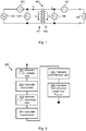
- Fig. 1 illustrates an example of a transformer 100 having a primary winding 101 and a secondary winding 102.
- the primary winding 101 is connected to a voltage source 103, which supplies the transformer with input power.
- a primary voltage measurement apparatus 104 is connected to the primary winding 101 of the transformer 100 for measuring the voltage over the primary winding 101.
- a primary current measurement apparatus 105 is connected to the primary winding for measuring the input current I H that flows into the transformer from the voltage source 103.
- the measured input current is designated I ⁇ H .
- the voltage source 103 may be a power grid. In this Fig.
- the voltage V H over the primary winding 101 is measured by the voltage measurement apparatus 104, but the measured voltage V ⁇ H is not equal to the voltage V H due to systematic errors in the voltage measurement apparatus 104.
- a voltage measurement apparatus 106 is connected and configured to measure the voltage V L over the secondary winding 102 of the transformer 100. The measured output voltage is designated V ⁇ L .
- a current measurement apparatus 107 is configured to measure the output current I L and the measured current is designated I ⁇ L , which is not equal to the output current IL due to systematic errors in the current measurement apparatus 107.
- a load 108 is also illustrated.
- the transformer is a three-phase transformer with three primary windings and three secondary windings.
- V H is the true voltage over the primary winding of the transformer
- ⁇ VH is a complex constant, which describes the error in the voltage measurement of the voltage over the primary winding of the transformer.
- I H is the true current and ⁇ IH is a complex constant that describes the error in the input current measurement.
- V ⁇ L is the measured voltage over the secondary winding of the transformer and I ⁇ L ⁇ is the complex conjugate of the measured current from the secondary winding of the transformer.
- V L is the true voltage over the secondary winding and ⁇ VL is a complex number that is representative of the systematic error in the measured voltage over the secondary winding.
- I L ⁇ is the complex conjugate of the true current from the secondary winding of the transformer, and finally ⁇ IL is a complex number which is representative of the systematic error in the measured current I ⁇ L from the secondary winding of the transformer.
- the present invention is based on the idea that by introducing correction factors for the voltage measurements and the current measurements, the calculation of a difference between two large almost equal large numbers can be made less influenced by sensor errors and thus closer to the true value.
- a first correction factor may be introduced for correcting current measurements. This is reasonable since current measurements usually are associated with the highest systematic errors.
- n I L / I H ⁇ I 0
- the turn's ratio, n, of a transformer is a very stable and precise quantity that only will change if there are severe problems with the transformer. If it is concluded or assumed that no such problems exist, the measured ratio n ⁇ reflects only the current measurement errors.
- the magnetization current l 0 is neglected since it is small compared to I H and I ⁇ H .
- the first correction factor is the complex conjugate of n ⁇ /n and is used to correct the measured input power in the equation (eq10) for the measured power loss.
- Equation (eq14) indicates that the error due to current measurements now influences the power loss only by a factor of the accuracy class of the current sensors.
- Z e is the short-circuit impedance referred to the primary side of the transformer.
- the second corrected power loss (eq18) contains an error in percent range of the actual loss compared to the error in the equation (eq10) above, which is much larger and in the percent of the actual power flowing through the transformer.
- FIG. 2 a flow diagram, illustrating an embodiment of a method for determining power loss is shown.
- the method for determining power loss in a transformer comprising:
- an additional step of calculating a voltage error ratio is performed, and the calculation of the corrected power loss further involves multiplying the output power with the voltage error ratio.
- the voltage error ratio may be calculated using equation (eq17).
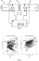
- Fig. 3 illustrates schematically a system, generally designated 300, for determining power loss of a transformer.
- the system 300 comprising an input voltage measurement apparatus 104 and an input current measurement apparatus 105 configured to be connected to a primary winding 101 of a transformer 100, and an output current measurement apparatus 107 and an output voltage measurement apparatus 106 configured to be connected to a secondary winding 102 of the transformer 100.
- the system 300 further comprises a calculation device 301 configured to be connected to the input current measurement apparatus 105, the input voltage measurement apparatus 104, the output current measurement apparatus 107, and the output voltage measurement apparatus 106.
- the calculation device 301 is configured to receive information about each measurement, which comprises measured voltages and currents.
- the calculation device 301 is configured to calculate the input power by multiplying the measured current and voltage of the primary side of the transformer, calculate a nominal error ratio.
- the calculation device is further configured to calculate the output power by multiplying the measured output current and output voltage on the secondary side of the transformer, calculate a first corrected power loss by means of multiplying the input power with the nominal error ratio and subtract the output power.
- the calculation of the nominal error ratio is performed by means of equation (eq13) and the complex correction factors for the input current measurement apparatus and the output current measurement apparatus.
- the calculation device calculates a voltage error ratio by means of equation (eq17) and the complex correction factors for the input voltage measurement apparatus and the output voltage measurement apparatus.
- the calculation device further calculates a second corrected power loss according to equation (eq18), which further involves multiplying the output power with the voltage error ratio.
- the second corrected power loss takes both the errors in the current measurement apparatuses and the voltage measurement apparatuses into account.
- the calculation device 301 further comprises a processor 302 and a memory 303.
- the memory comprises computer readable instructions for the processor, such that when the instructions are executed by the processor the method as disclosed above with reference to Fig. 2 is performed.
- the processor receives instructions from a signal that comprises computer readable instructions for the processor, such that when the instructions are executed by the processor the method as disclosed above with reference to Fig. 2 is performed.
- Fig. 4a shows measurement of the uncorrected power loss from a three-phase transformer with a rated power of 56 MVA.
- the horizontal axis is the load current and the vertical axis is the power loss.
- three clusters of measurements are visible.
- a first cluster 401 corresponds to phase 0
- a second cluster 402 corresponds to phase 1
- a third cluster 403 corresponds to phase 2. From this figure, several non-physical properties can be identified. First, for all three clusters the power loss is negative, which means that output power is larger than input power. Second, the power loss decreases with load current, which also is non-physical.
- a corrected power loss is disclosed.
- the corrected power loss in Fig. 4b is calculated using the method for estimating a second corrected power loss.
- the same three clusters as in Fig 4a ) are illustrated corrected.
- a corrected first cluster 401b corresponds to the first cluster 401a
- a corrected second cluster 402b corresponds to the second cluster 402a
- a corrected third cluster 403b corresponds to the third cluster 403a.
- all clusters provide positive power loss and a power loss that increases with load current.
- the power loss is estimated to be 0.5% of the load, this gives approximately 13 kW for a 56 MVA transformer. This estimation corresponds reasonable well to the power losses of the three clusters.
- Another advantage of some embodiments described herein is that they can easily be integrated and implemented in existing power plants.
Claims (8)
- Procédé (200) pour déterminer la perte de puissance dans un transformateur (100), comprenant les étapes suivantes :mesurer (201) la tension et le courant (V∼ H, I∼ H) sur un côté primaire (101) du transformateur (100) ;calculer (202) la puissance d'entrée en multipliant le courant et la tension mesurés sur le côté primaire du transformateur ;mesurer (203) la tension et le courant (V∼ L, I∼ L) sur un côté secondaire (102) du transformateur (100) ;calculer (204) la puissance de sortie en multipliant le courant et la tension mesurés sur le côté secondaire du transformateur ;calculer (205) un taux d'erreur nominal ;calculer (206) une première perte de puissance corrigée en multipliant la puissance d'entrée par un premier facteur de correction qui est le conjugué complexe du taux d'erreur nominal et en soustrayant la puissance de sortie,où le taux d'erreur nominal n∼/n est :

- Procédé selon la revendication 1, comprenant en outre l'étape suivante :calculer un rapport d'erreur de tension ; etoù le calcul de la perte de puissance corrigée implique en outre de multiplier la puissance de sortie par le taux d'erreur de tension.
- Procédé selon la revendication 2, dans lequel le rapport d'erreur de tension est :

- Système (300) pour déterminer la perte de puissance dans un transformateur, comprenant :un appareil de mesure de la tension d'entrée (104) et un appareil de mesure du courant d'entrée (105) configurés pour être connectés à un enroulement primaire (101) d'un transformateur (100), etun appareil de mesure du courant de sortie (107) et un appareil de mesure de la tension de sortie (106) configurés pour être connectés à un enroulement secondaire (102) du transformateur (100) ;un dispositif de calcul (301) configuré pour être connecté à l'appareil de mesure du courant d'entrée (105), à l'appareil de mesure de la tension d'entrée (104), à l'appareil de mesure du courant de sortie (107) et à l'appareil de mesure de la tension de sortie (106), le dispositif de calcul (301) étant configuré pour recevoir des informations sur chaque mesure, qui comprend des tensions et des courants mesurés, où le dispositif de calcul (301) est configuré pour :calculer la puissance d'entrée en multipliant le courant et la tension mesurés du côté primaire du transformateur ;calculer un taux d'erreur nominal ;calculer la puissance de sortie en multipliant le courant de sortie et la tension de sortie mesurés du côté secondaire du transformateur ;calculer une première perte de puissance corrigée en multipliant la puissance d'entrée par un premier facteur de correction qui est le conjugué complexe du taux d'erreur nominal, et soustraire la puissance de sortie,où le dispositif de calcul (301) est configuré pour calculer le taux d'erreur nominal comme étant :

- Système selon la revendication 4, dans lequel le dispositif de calcul (301) est en outre configuré pour :calculer un rapport d'erreur de tension ; etoù le calcul de la perte de puissance corrigée implique en outre de multiplier la puissance de sortie par le taux d'erreur de tension.
- Système selon la revendication 5, dans lequel le dispositif de calcul (301) est en outre configuré pour calculer le taux d'erreur de tension comme étant :

- Support lisible par ordinateur contenant des instructions pour un processeur (302), de manière à ce que, lorsque les instructions sont exécutées par le processeur, le processeur est amené à exécuter le procédé selon l'une quelconque des revendications 1 à 3 en utilisant le système de la revendication 4.
- Signal comprenant des instructions pour un processeur, de manière à ce que, lorsque les instructions sont exécutées par le processeur, le processeur est amené à exécuter le procédé selon l'une quelconque des revendications 1 à 3 en utilisant le système de la revendication 4.
Priority Applications (6)
| Application Number | Priority Date | Filing Date | Title |
|---|---|---|---|
| EP16156395.2A EP3208622B1 (fr) | 2016-02-18 | 2016-02-18 | Procédé et système de mesure de perte de puissance dans un transformateur de puissance |
| CN201780012155.9A CN108700627B (zh) | 2016-02-18 | 2017-02-13 | 用于测量电力变压器中的功率损耗的方法和系统 |
| CA3014505A CA3014505C (fr) | 2016-02-18 | 2017-02-13 | Procede et systeme de mesure de perte de puissance dans un transformateur de puissance |
| PCT/EP2017/053137 WO2017140616A1 (fr) | 2016-02-18 | 2017-02-13 | Procédé et système de mesure de perte de puissance dans un transformateur de puissance |
| BR112018013991-2A BR112018013991B1 (pt) | 2016-02-18 | 2017-02-13 | Sistema e método para determinar perda de energia em um transformador, meio legível por computador e sinal |
| US16/075,858 US10416209B2 (en) | 2016-02-18 | 2017-02-13 | Method and system for measuring power loss in a power transformer |
Applications Claiming Priority (1)
| Application Number | Priority Date | Filing Date | Title |
|---|---|---|---|
| EP16156395.2A EP3208622B1 (fr) | 2016-02-18 | 2016-02-18 | Procédé et système de mesure de perte de puissance dans un transformateur de puissance |
Publications (2)
| Publication Number | Publication Date |
|---|---|
| EP3208622A1 EP3208622A1 (fr) | 2017-08-23 |
| EP3208622B1 true EP3208622B1 (fr) | 2021-01-20 |
Family
ID=55411254
Family Applications (1)
| Application Number | Title | Priority Date | Filing Date |
|---|---|---|---|
| EP16156395.2A Active EP3208622B1 (fr) | 2016-02-18 | 2016-02-18 | Procédé et système de mesure de perte de puissance dans un transformateur de puissance |
Country Status (5)
| Country | Link |
|---|---|
| US (1) | US10416209B2 (fr) |
| EP (1) | EP3208622B1 (fr) |
| CN (1) | CN108700627B (fr) |
| CA (1) | CA3014505C (fr) |
| WO (1) | WO2017140616A1 (fr) |
Families Citing this family (3)
| Publication number | Priority date | Publication date | Assignee | Title |
|---|---|---|---|---|
| CN109565171B (zh) * | 2016-08-29 | 2020-08-07 | 华为技术有限公司 | 充电保护方法、终端及充电器 |
| CN111337744A (zh) * | 2020-04-03 | 2020-06-26 | 苏州华电电气股份有限公司 | 变压器运行能效和/或损耗监测装置 |
| CN114336721A (zh) * | 2022-01-06 | 2022-04-12 | 国网湖北省电力有限公司营销服务中心(计量中心) | 直流输电系统换流站损耗状态分级预警方法 |
Family Cites Families (12)
| Publication number | Priority date | Publication date | Assignee | Title |
|---|---|---|---|---|
| US3732489A (en) * | 1972-02-07 | 1973-05-08 | Detroit Edison Co | Transformer phase angle error and ratio correction factor transducer |
| US6809525B1 (en) * | 2002-12-31 | 2004-10-26 | Abb Technology Ag | Method and system for estimating conductor losses in a transformer |
| US7444248B2 (en) * | 2005-04-29 | 2008-10-28 | General Electric Company | System and method for synchronized phasor measurement |
| US7480580B2 (en) * | 2005-10-18 | 2009-01-20 | Schweitzer Engineering Laboratories, Inc. | Apparatus and method for estimating synchronized phasors at predetermined times referenced to an absolute time standard in an electrical system |
| US7598751B2 (en) * | 2006-08-14 | 2009-10-06 | Clemson University Research Foundation | Impedance-based arc fault determination device (IADD) and method |
| CN100527181C (zh) * | 2007-11-02 | 2009-08-12 | 江苏通驰自动化系统有限公司 | 配电变压器自动计量装置 |
| US8494795B2 (en) * | 2008-05-05 | 2013-07-23 | Schweitzer Engineering Laboratories Inc | Apparatus and method for estimating synchronized phasors at predetermined times referenced to a common time standard in an electrical system |
| US8140283B2 (en) * | 2008-12-24 | 2012-03-20 | Schweitzer Engineering Laboratories, Inc. | Independent frequency measurement and tracking |
| US8635034B2 (en) * | 2010-12-16 | 2014-01-21 | General Electric Company | Method and system for monitoring transformer health |
| ES2439279T3 (es) * | 2010-12-17 | 2014-01-22 | Abb Research Ltd. | Método y aparato para diagnóstico de transformador |
| JP5416735B2 (ja) * | 2011-04-28 | 2014-02-12 | 株式会社日立製作所 | 電力監視制御装置および電力監視制御システム |
| CN104215825A (zh) * | 2014-08-20 | 2014-12-17 | 国家电网公司 | 一种电力变压器综合在线监测系统 |
-
2016
- 2016-02-18 EP EP16156395.2A patent/EP3208622B1/fr active Active
-
2017
- 2017-02-13 CA CA3014505A patent/CA3014505C/fr active Active
- 2017-02-13 CN CN201780012155.9A patent/CN108700627B/zh active Active
- 2017-02-13 WO PCT/EP2017/053137 patent/WO2017140616A1/fr active Application Filing
- 2017-02-13 US US16/075,858 patent/US10416209B2/en active Active
Non-Patent Citations (1)
| Title |
|---|
| None * |
Also Published As
| Publication number | Publication date |
|---|---|
| EP3208622A1 (fr) | 2017-08-23 |
| BR112018013991A8 (pt) | 2022-12-20 |
| CA3014505C (fr) | 2020-01-28 |
| US10416209B2 (en) | 2019-09-17 |
| CN108700627A (zh) | 2018-10-23 |
| CA3014505A1 (fr) | 2017-08-24 |
| WO2017140616A1 (fr) | 2017-08-24 |
| BR112018013991A2 (pt) | 2018-12-11 |
| US20190041437A1 (en) | 2019-02-07 |
| CN108700627B (zh) | 2019-12-10 |
Similar Documents
| Publication | Publication Date | Title |
|---|---|---|
| EP1939638B1 (fr) | Système et procédé de localisation d'un défaut phase-terre | |
| US7836779B2 (en) | Method for operating an electromagnetic flowmeter and electromagnetic flowmeter | |
| US7996116B2 (en) | Method of determining voltage stability margin for load shedding within an electrical power system | |
| US20080297163A1 (en) | Method for determining location of phase-to-earth fault | |
| EP3208622B1 (fr) | Procédé et système de mesure de perte de puissance dans un transformateur de puissance | |
| US8933709B2 (en) | Method for determining residual coupling of an inductive conductivity sensor | |
| EP3548908B1 (fr) | Détection de courant de moteur | |
| JP6373730B2 (ja) | 変流器を含む電源装置及び変流器の補償方法 | |
| EP2682768B1 (fr) | Procédé et appareil pour déterminer la distance à un défaut de phase à la terre | |
| US11112434B2 (en) | Sensor apparatus for measuring direct and alternating currents | |
| EP2397864A1 (fr) | Compteur d'électricité et procédé pour déterminer une quantité | |
| JP2007071774A (ja) | 絶縁測定方法及び装置 | |
| JP2011058826A (ja) | 地絡電流検出方法及び検出装置 | |
| JP4993728B2 (ja) | 有効漏れ電流測定器 | |
| JP5464908B2 (ja) | 電力系統インピーダンス推定装置および電力系統インピーダンス推定方法 | |
| JP2009020114A (ja) | 電流センサにおけるdcの影響を検出する方法およびシステム | |
| JP2008026170A (ja) | 地絡点標定方法および装置 | |
| EP1437813B1 (fr) | Dispositif et procédé pour détection des défauts de terre | |
| US8872530B2 (en) | Method for correcting the voltage measured across the terminals of a sensor | |
| US20160356821A1 (en) | Current sensors | |
| JP6897933B2 (ja) | 高圧絶縁監視装置及び高圧絶縁監視方法 | |
| US11022630B2 (en) | Measurement of current within a conductor | |
| JP3676486B2 (ja) | 地絡検出装置 | |
| JP2010060313A (ja) | 変流器の異常検査試験装置 | |
| EP3942308B1 (fr) | Validation d'une mesure d'énergie d'une composante fondamentale uniquement |
Legal Events
| Date | Code | Title | Description |
|---|---|---|---|
| PUAI | Public reference made under article 153(3) epc to a published international application that has entered the european phase |
Free format text: ORIGINAL CODE: 0009012 |
|
| STAA | Information on the status of an ep patent application or granted ep patent |
Free format text: STATUS: THE APPLICATION HAS BEEN PUBLISHED |
|
| AK | Designated contracting states |
Kind code of ref document: A1 Designated state(s): AL AT BE BG CH CY CZ DE DK EE ES FI FR GB GR HR HU IE IS IT LI LT LU LV MC MK MT NL NO PL PT RO RS SE SI SK SM TR |
|
| AX | Request for extension of the european patent |
Extension state: BA ME |
|
| STAA | Information on the status of an ep patent application or granted ep patent |
Free format text: STATUS: REQUEST FOR EXAMINATION WAS MADE |
|
| 17P | Request for examination filed |
Effective date: 20180223 |
|
| RBV | Designated contracting states (corrected) |
Designated state(s): AL AT BE BG CH CY CZ DE DK EE ES FI FR GB GR HR HU IE IS IT LI LT LU LV MC MK MT NL NO PL PT RO RS SE SI SK SM TR |
|
| RAP1 | Party data changed (applicant data changed or rights of an application transferred) |
Owner name: ABB POWER GRIDS SWITZERLAND AG |
|
| REG | Reference to a national code |
Ref country code: DE Ref legal event code: R079 Ref document number: 602016051588 Country of ref document: DE Free format text: PREVIOUS MAIN CLASS: G01R0031020000 Ipc: G01R0031620000 |
|
| GRAP | Despatch of communication of intention to grant a patent |
Free format text: ORIGINAL CODE: EPIDOSNIGR1 |
|
| STAA | Information on the status of an ep patent application or granted ep patent |
Free format text: STATUS: GRANT OF PATENT IS INTENDED |
|
| RIC1 | Information provided on ipc code assigned before grant |
Ipc: G01R 21/133 20060101ALI20201002BHEP Ipc: G01R 31/62 20200101AFI20201002BHEP |
|
| INTG | Intention to grant announced |
Effective date: 20201105 |
|
| GRAS | Grant fee paid |
Free format text: ORIGINAL CODE: EPIDOSNIGR3 |
|
| GRAA | (expected) grant |
Free format text: ORIGINAL CODE: 0009210 |
|
| STAA | Information on the status of an ep patent application or granted ep patent |
Free format text: STATUS: THE PATENT HAS BEEN GRANTED |
|
| AK | Designated contracting states |
Kind code of ref document: B1 Designated state(s): AL AT BE BG CH CY CZ DE DK EE ES FI FR GB GR HR HU IE IS IT LI LT LU LV MC MK MT NL NO PL PT RO RS SE SI SK SM TR |
|
| REG | Reference to a national code |
Ref country code: GB Ref legal event code: FG4D |
|
| REG | Reference to a national code |
Ref country code: CH Ref legal event code: EP |
|
| REG | Reference to a national code |
Ref country code: DE Ref legal event code: R096 Ref document number: 602016051588 Country of ref document: DE |
|
| REG | Reference to a national code |
Ref country code: AT Ref legal event code: REF Ref document number: 1356869 Country of ref document: AT Kind code of ref document: T Effective date: 20210215 |
|
| REG | Reference to a national code |
Ref country code: IE Ref legal event code: FG4D |
|
| REG | Reference to a national code |
Ref country code: NL Ref legal event code: MP Effective date: 20210120 |
|
| REG | Reference to a national code |
Ref country code: LT Ref legal event code: MG9D |
|
| REG | Reference to a national code |
Ref country code: AT Ref legal event code: MK05 Ref document number: 1356869 Country of ref document: AT Kind code of ref document: T Effective date: 20210120 |
|
| PG25 | Lapsed in a contracting state [announced via postgrant information from national office to epo] |
Ref country code: NO Free format text: LAPSE BECAUSE OF FAILURE TO SUBMIT A TRANSLATION OF THE DESCRIPTION OR TO PAY THE FEE WITHIN THE PRESCRIBED TIME-LIMIT Effective date: 20210420 Ref country code: PT Free format text: LAPSE BECAUSE OF FAILURE TO SUBMIT A TRANSLATION OF THE DESCRIPTION OR TO PAY THE FEE WITHIN THE PRESCRIBED TIME-LIMIT Effective date: 20210520 Ref country code: BG Free format text: LAPSE BECAUSE OF FAILURE TO SUBMIT A TRANSLATION OF THE DESCRIPTION OR TO PAY THE FEE WITHIN THE PRESCRIBED TIME-LIMIT Effective date: 20210420 Ref country code: HR Free format text: LAPSE BECAUSE OF FAILURE TO SUBMIT A TRANSLATION OF THE DESCRIPTION OR TO PAY THE FEE WITHIN THE PRESCRIBED TIME-LIMIT Effective date: 20210120 Ref country code: FI Free format text: LAPSE BECAUSE OF FAILURE TO SUBMIT A TRANSLATION OF THE DESCRIPTION OR TO PAY THE FEE WITHIN THE PRESCRIBED TIME-LIMIT Effective date: 20210120 Ref country code: GR Free format text: LAPSE BECAUSE OF FAILURE TO SUBMIT A TRANSLATION OF THE DESCRIPTION OR TO PAY THE FEE WITHIN THE PRESCRIBED TIME-LIMIT Effective date: 20210421 Ref country code: LT Free format text: LAPSE BECAUSE OF FAILURE TO SUBMIT A TRANSLATION OF THE DESCRIPTION OR TO PAY THE FEE WITHIN THE PRESCRIBED TIME-LIMIT Effective date: 20210120 |
|
| PG25 | Lapsed in a contracting state [announced via postgrant information from national office to epo] |
Ref country code: AT Free format text: LAPSE BECAUSE OF FAILURE TO SUBMIT A TRANSLATION OF THE DESCRIPTION OR TO PAY THE FEE WITHIN THE PRESCRIBED TIME-LIMIT Effective date: 20210120 Ref country code: LV Free format text: LAPSE BECAUSE OF FAILURE TO SUBMIT A TRANSLATION OF THE DESCRIPTION OR TO PAY THE FEE WITHIN THE PRESCRIBED TIME-LIMIT Effective date: 20210120 Ref country code: PL Free format text: LAPSE BECAUSE OF FAILURE TO SUBMIT A TRANSLATION OF THE DESCRIPTION OR TO PAY THE FEE WITHIN THE PRESCRIBED TIME-LIMIT Effective date: 20210120 Ref country code: RS Free format text: LAPSE BECAUSE OF FAILURE TO SUBMIT A TRANSLATION OF THE DESCRIPTION OR TO PAY THE FEE WITHIN THE PRESCRIBED TIME-LIMIT Effective date: 20210120 Ref country code: SE Free format text: LAPSE BECAUSE OF FAILURE TO SUBMIT A TRANSLATION OF THE DESCRIPTION OR TO PAY THE FEE WITHIN THE PRESCRIBED TIME-LIMIT Effective date: 20210120 |
|
| PG25 | Lapsed in a contracting state [announced via postgrant information from national office to epo] |
Ref country code: IS Free format text: LAPSE BECAUSE OF FAILURE TO SUBMIT A TRANSLATION OF THE DESCRIPTION OR TO PAY THE FEE WITHIN THE PRESCRIBED TIME-LIMIT Effective date: 20210520 |
|
| REG | Reference to a national code |
Ref country code: DE Ref legal event code: R097 Ref document number: 602016051588 Country of ref document: DE |
|
| REG | Reference to a national code |
Ref country code: BE Ref legal event code: MM Effective date: 20210228 |
|
| PG25 | Lapsed in a contracting state [announced via postgrant information from national office to epo] |
Ref country code: CH Free format text: LAPSE BECAUSE OF NON-PAYMENT OF DUE FEES Effective date: 20210228 Ref country code: SM Free format text: LAPSE BECAUSE OF FAILURE TO SUBMIT A TRANSLATION OF THE DESCRIPTION OR TO PAY THE FEE WITHIN THE PRESCRIBED TIME-LIMIT Effective date: 20210120 Ref country code: LI Free format text: LAPSE BECAUSE OF NON-PAYMENT OF DUE FEES Effective date: 20210228 Ref country code: LU Free format text: LAPSE BECAUSE OF NON-PAYMENT OF DUE FEES Effective date: 20210218 Ref country code: MC Free format text: LAPSE BECAUSE OF FAILURE TO SUBMIT A TRANSLATION OF THE DESCRIPTION OR TO PAY THE FEE WITHIN THE PRESCRIBED TIME-LIMIT Effective date: 20210120 Ref country code: CZ Free format text: LAPSE BECAUSE OF FAILURE TO SUBMIT A TRANSLATION OF THE DESCRIPTION OR TO PAY THE FEE WITHIN THE PRESCRIBED TIME-LIMIT Effective date: 20210120 Ref country code: EE Free format text: LAPSE BECAUSE OF FAILURE TO SUBMIT A TRANSLATION OF THE DESCRIPTION OR TO PAY THE FEE WITHIN THE PRESCRIBED TIME-LIMIT Effective date: 20210120 |
|
| PLBE | No opposition filed within time limit |
Free format text: ORIGINAL CODE: 0009261 |
|
| STAA | Information on the status of an ep patent application or granted ep patent |
Free format text: STATUS: NO OPPOSITION FILED WITHIN TIME LIMIT |
|
| PG25 | Lapsed in a contracting state [announced via postgrant information from national office to epo] |
Ref country code: DK Free format text: LAPSE BECAUSE OF FAILURE TO SUBMIT A TRANSLATION OF THE DESCRIPTION OR TO PAY THE FEE WITHIN THE PRESCRIBED TIME-LIMIT Effective date: 20210120 Ref country code: SK Free format text: LAPSE BECAUSE OF FAILURE TO SUBMIT A TRANSLATION OF THE DESCRIPTION OR TO PAY THE FEE WITHIN THE PRESCRIBED TIME-LIMIT Effective date: 20210120 Ref country code: RO Free format text: LAPSE BECAUSE OF FAILURE TO SUBMIT A TRANSLATION OF THE DESCRIPTION OR TO PAY THE FEE WITHIN THE PRESCRIBED TIME-LIMIT Effective date: 20210120 |
|
| 26N | No opposition filed |
Effective date: 20211021 |
|
| PG25 | Lapsed in a contracting state [announced via postgrant information from national office to epo] |
Ref country code: IE Free format text: LAPSE BECAUSE OF NON-PAYMENT OF DUE FEES Effective date: 20210218 Ref country code: AL Free format text: LAPSE BECAUSE OF FAILURE TO SUBMIT A TRANSLATION OF THE DESCRIPTION OR TO PAY THE FEE WITHIN THE PRESCRIBED TIME-LIMIT Effective date: 20210120 Ref country code: ES Free format text: LAPSE BECAUSE OF FAILURE TO SUBMIT A TRANSLATION OF THE DESCRIPTION OR TO PAY THE FEE WITHIN THE PRESCRIBED TIME-LIMIT Effective date: 20210120 |
|
| PG25 | Lapsed in a contracting state [announced via postgrant information from national office to epo] |
Ref country code: SI Free format text: LAPSE BECAUSE OF FAILURE TO SUBMIT A TRANSLATION OF THE DESCRIPTION OR TO PAY THE FEE WITHIN THE PRESCRIBED TIME-LIMIT Effective date: 20210120 |
|
| PG25 | Lapsed in a contracting state [announced via postgrant information from national office to epo] |
Ref country code: IT Free format text: LAPSE BECAUSE OF FAILURE TO SUBMIT A TRANSLATION OF THE DESCRIPTION OR TO PAY THE FEE WITHIN THE PRESCRIBED TIME-LIMIT Effective date: 20210120 |
|
| PG25 | Lapsed in a contracting state [announced via postgrant information from national office to epo] |
Ref country code: IS Free format text: LAPSE BECAUSE OF FAILURE TO SUBMIT A TRANSLATION OF THE DESCRIPTION OR TO PAY THE FEE WITHIN THE PRESCRIBED TIME-LIMIT Effective date: 20210520 |
|
| REG | Reference to a national code |
Ref country code: DE Ref legal event code: R081 Ref document number: 602016051588 Country of ref document: DE Owner name: HITACHI ENERGY SWITZERLAND AG, CH Free format text: FORMER OWNER: ABB POWER GRIDS SWITZERLAND AG, BADEN, CH Ref country code: DE Ref legal event code: R081 Ref document number: 602016051588 Country of ref document: DE Owner name: HITACHI ENERGY LTD, CH Free format text: FORMER OWNER: ABB POWER GRIDS SWITZERLAND AG, BADEN, CH |
|
| PG25 | Lapsed in a contracting state [announced via postgrant information from national office to epo] |
Ref country code: BE Free format text: LAPSE BECAUSE OF NON-PAYMENT OF DUE FEES Effective date: 20210228 |
|
| PGFP | Annual fee paid to national office [announced via postgrant information from national office to epo] |
Ref country code: FR Payment date: 20230221 Year of fee payment: 8 |
|
| PG25 | Lapsed in a contracting state [announced via postgrant information from national office to epo] |
Ref country code: HU Free format text: LAPSE BECAUSE OF FAILURE TO SUBMIT A TRANSLATION OF THE DESCRIPTION OR TO PAY THE FEE WITHIN THE PRESCRIBED TIME-LIMIT; INVALID AB INITIO Effective date: 20160218 |
|
| PGFP | Annual fee paid to national office [announced via postgrant information from national office to epo] |
Ref country code: GB Payment date: 20230221 Year of fee payment: 8 Ref country code: DE Payment date: 20230216 Year of fee payment: 8 |
|
| PG25 | Lapsed in a contracting state [announced via postgrant information from national office to epo] |
Ref country code: NL Free format text: LAPSE BECAUSE OF NON-PAYMENT OF DUE FEES Effective date: 20210120 Ref country code: CY Free format text: LAPSE BECAUSE OF FAILURE TO SUBMIT A TRANSLATION OF THE DESCRIPTION OR TO PAY THE FEE WITHIN THE PRESCRIBED TIME-LIMIT Effective date: 20210120 |
|
| P01 | Opt-out of the competence of the unified patent court (upc) registered |
Effective date: 20230527 |
|
| REG | Reference to a national code |
Ref country code: DE Ref legal event code: R082 Ref document number: 602016051588 Country of ref document: DE Representative=s name: DENNEMEYER & ASSOCIATES S.A., DE Ref country code: DE Ref legal event code: R081 Ref document number: 602016051588 Country of ref document: DE Owner name: HITACHI ENERGY LTD, CH Free format text: FORMER OWNER: HITACHI ENERGY SWITZERLAND AG, BADEN, CH |