EP3208577B1 - Verfahren und vorrichtung zur messung des flüssigkeitsniveaus in einem flüssigkeitsbehälter - Google Patents
Verfahren und vorrichtung zur messung des flüssigkeitsniveaus in einem flüssigkeitsbehälter Download PDFInfo
- Publication number
- EP3208577B1 EP3208577B1 EP16156174.1A EP16156174A EP3208577B1 EP 3208577 B1 EP3208577 B1 EP 3208577B1 EP 16156174 A EP16156174 A EP 16156174A EP 3208577 B1 EP3208577 B1 EP 3208577B1
- Authority
- EP
- European Patent Office
- Prior art keywords
- volume
- valve member
- reservoir
- signal
- port
- Prior art date
- Legal status (The legal status is an assumption and is not a legal conclusion. Google has not performed a legal analysis and makes no representation as to the accuracy of the status listed.)
- Active
Links
- 239000007788 liquid Substances 0.000 title claims description 31
- 238000000034 method Methods 0.000 title claims description 27
- 238000004891 communication Methods 0.000 claims description 47
- 239000012530 fluid Substances 0.000 claims description 46
- 230000008859 change Effects 0.000 claims description 22
- 230000000737 periodic effect Effects 0.000 claims description 8
- 239000007789 gas Substances 0.000 description 41
- OKTJSMMVPCPJKN-UHFFFAOYSA-N Carbon Chemical compound [C] OKTJSMMVPCPJKN-UHFFFAOYSA-N 0.000 description 16
- 230000004044 response Effects 0.000 description 15
- 239000002828 fuel tank Substances 0.000 description 12
- 238000002485 combustion reaction Methods 0.000 description 10
- 238000005259 measurement Methods 0.000 description 10
- 230000003190 augmentative effect Effects 0.000 description 6
- 239000000446 fuel Substances 0.000 description 6
- 238000001514 detection method Methods 0.000 description 5
- 238000013459 approach Methods 0.000 description 3
- 239000003638 chemical reducing agent Substances 0.000 description 3
- 238000010586 diagram Methods 0.000 description 3
- 239000000428 dust Substances 0.000 description 3
- 230000001965 increasing effect Effects 0.000 description 3
- 238000002955 isolation Methods 0.000 description 3
- MWUXSHHQAYIFBG-UHFFFAOYSA-N nitrogen oxide Inorganic materials O=[N] MWUXSHHQAYIFBG-UHFFFAOYSA-N 0.000 description 3
- 238000012545 processing Methods 0.000 description 3
- QGZKDVFQNNGYKY-UHFFFAOYSA-N Ammonia Chemical compound N QGZKDVFQNNGYKY-UHFFFAOYSA-N 0.000 description 2
- 230000001133 acceleration Effects 0.000 description 2
- 230000003321 amplification Effects 0.000 description 2
- 238000013461 design Methods 0.000 description 2
- 230000000694 effects Effects 0.000 description 2
- 230000007613 environmental effect Effects 0.000 description 2
- 238000009434 installation Methods 0.000 description 2
- 230000010354 integration Effects 0.000 description 2
- 238000003199 nucleic acid amplification method Methods 0.000 description 2
- 230000009467 reduction Effects 0.000 description 2
- 238000006722 reduction reaction Methods 0.000 description 2
- 239000013598 vector Substances 0.000 description 2
- VHUUQVKOLVNVRT-UHFFFAOYSA-N Ammonium hydroxide Chemical compound [NH4+].[OH-] VHUUQVKOLVNVRT-UHFFFAOYSA-N 0.000 description 1
- XSQUKJJJFZCRTK-UHFFFAOYSA-N Urea Chemical compound NC(N)=O XSQUKJJJFZCRTK-UHFFFAOYSA-N 0.000 description 1
- 230000004075 alteration Effects 0.000 description 1
- 238000010420 art technique Methods 0.000 description 1
- 230000003416 augmentation Effects 0.000 description 1
- 230000008901 benefit Effects 0.000 description 1
- 238000009530 blood pressure measurement Methods 0.000 description 1
- 239000004202 carbamide Substances 0.000 description 1
- 238000010531 catalytic reduction reaction Methods 0.000 description 1
- 239000003610 charcoal Substances 0.000 description 1
- 230000007423 decrease Effects 0.000 description 1
- 230000001934 delay Effects 0.000 description 1
- 230000001419 dependent effect Effects 0.000 description 1
- 230000002708 enhancing effect Effects 0.000 description 1
- 230000002349 favourable effect Effects 0.000 description 1
- 239000003302 ferromagnetic material Substances 0.000 description 1
- 238000004519 manufacturing process Methods 0.000 description 1
- 238000003825 pressing Methods 0.000 description 1
- 238000010926 purge Methods 0.000 description 1
- 238000007789 sealing Methods 0.000 description 1
- 238000000926 separation method Methods 0.000 description 1
- 230000001360 synchronised effect Effects 0.000 description 1
- 230000002123 temporal effect Effects 0.000 description 1
- 238000013519 translation Methods 0.000 description 1
- 239000012855 volatile organic compound Substances 0.000 description 1
Images


Classifications
-
- G—PHYSICS
- G01—MEASURING; TESTING
- G01F—MEASURING VOLUME, VOLUME FLOW, MASS FLOW OR LIQUID LEVEL; METERING BY VOLUME
- G01F22/00—Methods or apparatus for measuring volume of fluids or fluent solid material, not otherwise provided for
- G01F22/02—Methods or apparatus for measuring volume of fluids or fluent solid material, not otherwise provided for involving measurement of pressure
-
- G—PHYSICS
- G01—MEASURING; TESTING
- G01F—MEASURING VOLUME, VOLUME FLOW, MASS FLOW OR LIQUID LEVEL; METERING BY VOLUME
- G01F23/00—Indicating or measuring liquid level or level of fluent solid material, e.g. indicating in terms of volume or indicating by means of an alarm
- G01F23/14—Indicating or measuring liquid level or level of fluent solid material, e.g. indicating in terms of volume or indicating by means of an alarm by measurement of pressure
- G01F23/18—Indicating, recording or alarm devices actuated electrically
-
- G—PHYSICS
- G01—MEASURING; TESTING
- G01F—MEASURING VOLUME, VOLUME FLOW, MASS FLOW OR LIQUID LEVEL; METERING BY VOLUME
- G01F23/00—Indicating or measuring liquid level or level of fluent solid material, e.g. indicating in terms of volume or indicating by means of an alarm
- G01F23/80—Arrangements for signal processing
-
- G—PHYSICS
- G01—MEASURING; TESTING
- G01F—MEASURING VOLUME, VOLUME FLOW, MASS FLOW OR LIQUID LEVEL; METERING BY VOLUME
- G01F17/00—Methods or apparatus for determining the capacity of containers or cavities, or the volume of solid bodies
-
- G—PHYSICS
- G01—MEASURING; TESTING
- G01F—MEASURING VOLUME, VOLUME FLOW, MASS FLOW OR LIQUID LEVEL; METERING BY VOLUME
- G01F23/00—Indicating or measuring liquid level or level of fluent solid material, e.g. indicating in terms of volume or indicating by means of an alarm
- G01F23/14—Indicating or measuring liquid level or level of fluent solid material, e.g. indicating in terms of volume or indicating by means of an alarm by measurement of pressure
Landscapes
- Physics & Mathematics (AREA)
- Fluid Mechanics (AREA)
- General Physics & Mathematics (AREA)
- Engineering & Computer Science (AREA)
- Signal Processing (AREA)
- Measuring Fluid Pressure (AREA)
- Control Of Fluid Pressure (AREA)
Claims (13)
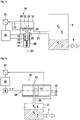
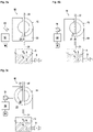
- Eine Vorrichtung zum Verändern eines Gasvolumens (Vg (t)) in einem Reservoir (5), aufweisend zumindest ein Ventil (10), wobei das Ventil (10) zumindest einen ersten Anschluss (21) aufweist, der in Fluidverbindung mit dem Reservoir (5) steht, einen zweiten Anschluss (22) und eine Leitung (31) zum Ermöglichen einer Fluidverbindung zwischen dem ersten Anschluss (21) und dem zweiten Anschluss (22) und einem Ventilelement (30), wobei das Ventilelement (30) beweglich ist zwischen zumindest(i) einer offenen Position, in der der erste Anschluss (21) und der zweite Anschluss (22) über die Leitung (31) in Fluidverbindung stehen und(ii) einer ersten geschlossenen Position, in welcher die Fluidverbindung zwischen dem ersten Anschluss (21) und dem zweiten Anschluss (22) durch das Ventilelement (30) blockiert ist,dadurch gekennzeichnet, dass
das Ventilelement (30) in zumindest eine zweite geschlossene Position bewegbar ist, in welcher die Fluidverbindung zwischen dem ersten Anschluss (21) und dem zweiten Anschluss (22) durch das Ventilelement (30) blockiert ist und dass das Volumen einer Kammer (23), welche in Flüssigkeitsverbindung mit dem ersten Anschluss (21) steht, geändert wird, wenn das Ventilelement (30) von der ersten geschlossenen Position in die zweite geschlossene Position und/oder von der zweiten in die erste geschlossene Position bewegt wird. - Die Vorrichtung gemäß Anspruch 1, dadurch gekennzeichnet, dass die Vorrichtung einen Sensor aufweist, der ein Signal bereitstellt, das repräsentativ ist für die Kraft F, die erforderlich ist, um das Ventilelement (30) gegen den Druck (p) im Reservoir (5) von der ersten zur zweiten geschlossenen Position und/oder von der zweiten zur ersten geschlossenen Position zu bewegen.
- Die Vorrichtung gemäß Anspruch 1 oder 2, dadurch gekennzeichnet, dass die Leitung (24, 31) einen Ventilsitz (20) aufweist und das Ventilelement (30) den Ventilsitz (20) in seiner ersten und zweiten geschlossenen Position verschließt und den Ventilsitz in seiner offener Position öffnet, wobei eine elastische Dichtung (35) zwischen dem Ventilsitz (20) und dem Ventilelement (30) positioniert ist und die elastische Dichtung (35) komprimiert wird, wenn das Ventilelement (30) aus seiner ersten zur zweiten geschlossenen Position bewegt wird und dekomprimiert wird, wenn das Ventilelement (30) aus seiner zweiten in seine erste geschlossene Position bewegt wird.
- Die Vorrichtung gemäß einem der Ansprüche 1 bis 3, dadurch gekennzeichnet, dass das Ventilelement (30) zumindest einen Abschnitt der Leitung (31) aufweist, wobei- die Leitung (31) zumindest eine erste Öffnung hat, welche vor dem ersten Anschluss (21) positioniert ist, und eine zweite Öffnung, welche vor einem zweiten Anschluss (22) positioniert ist, wenn sich das Ventilelement (30) in seiner offenen Position befindet, um dadurch die Fluidverbindung bereitzustellen,- der erste Anschluss (21) in Fluidverbindung mit einer Kammer (23) steht, in welche das Ventilelement (30) hineinragt, wenn das Ventilelement (30) von seiner ersten in seine zweite geschlossene Position bewegt wird,- die Begrenzung der Kammer (23) zumindest eine der ersten und/oder zweiten Öffnungen der Leitung (31) verschließt, wenn das Ventilelement (30) aus seiner offenen Position in seine erste und/oder zweite geschlossene Position bewegt wird.
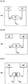
- Ein Verfahren zum Messen einer Druckänderung aufgrund einer Volumenänderung eines Reservoirs (5), das ein Gas (6) einschließt, wobei das Verfahren aufweist:- Ändern des Volumens des Reservoirs (5) gemäß einem ersten Anfangssignal (S(t), S1(t)) durch eine erste Volumenänderung (ΔV1 ),- Erhalten eines Drucksignals (p1(t)), das für den Druck im Reservoir (5) als Funktion der Zeit (t) repräsentativ ist, und- Demodulieren des Drucksignals (p1(t)) unter Verwendung des ersten Anfangssignals (S(t), S1(t)) als Referenzsignaldadurch gekennzeichnet, dass
das Reservoir (5) in Fluidverbindung mit dem ersten Anschluss (21) der Vorrichtung nach einem der Ansprüche 1 bis 4 steht und dass das Ändern des Volumens durch Änderung der Position des Ventilelements (30) zwischen zumindest zwei der geschlossenen Positionen gemäß dem ersten Anfangssignal (S(t ),S1(t)) erreicht wird. - Das Verfahren gemäß Anspruch 5,
dadurch gekennzeichnet, dass
der Demodulationsschritt das Multiplizieren des Referenzsignals (S(t), S1(t)) mit dem Drucksignal (p1(t)) aufweist, wodurch ein demoduliertes Drucksignal (p d,1 x (t)) erhalten wird. - Das Verfahren gemäß Anspruch 5,
dadurch gekennzeichnet, dass
der Demodulationsschritt das Multiplizieren eines phasenverschobenen Referenzsignals (S(t - π/2),S1(t - π/2)) mit dem Drucksignal (p1(t)) aufweist, wodurch ein zweites demoduliertes Drucksignal (p d,1Y (t)) erhalten wird. - Das Verfahren gemäß den Ansprüchen 6 oder 7,
dadurch gekennzeichnet, dass das demodulierte Drucksignal gegeben ist durch
- Das Verfahren gemäß den Ansprüchen 6 oder 7,
dadurch gekennzeichnet, dass das demodulierte Drucksignal (p d,1(t)) integriert ist und/oder das Drucksignal vor seiner Demodulation verstärkt wird. - Das Verfahren gemäß einem der Ansprüche 5 bis 9,
dadurch gekennzeichnet, dass es weiterhin aufweist:- Verändern des Volumens des Reservoirs (5) gemäß einem zweiten Anfangssignal (S 2(t)) durch eine zweite Volumenänderung (ΔV 2),- Erhalten eines zweiten Drucksignals (p2 (t)), das für den Druck im Reservoir (5) als Funktion der Zeit (t) repräsentativ ist, und- Demodulieren des Drucksignals (p2(t)) unter Verwendung des zweiten Anfangssignals (S 2(t)) als Referenzsignal, wodurch ein zweites demoduliertes Drucksignal (p d,2(t)) erhalten wird. - Das Verfahren nach einem der Ansprüche 5 bis 10,
dadurch gekennzeichnet, dass- das Verändern des Volumens des Reservoirs (5) gemäß einem Anfangssignal (S(t)) ein Verändern des Volumens durch eine erste Volumenänderung (ΔV1 ) gemäß einem ersten Anfangssignal (S1(t)) beinhaltet, und zur gleichen Zeit durch eine zweite Volumenänderung (ΔV2 ) gemäß einem zweiten Anfangssignal (S 2(t)) zur gleichen Zeit durch Modulieren des Volumens mit einer Superposition der ersten und zweiten Volumenänderungen (ΔV1,ΔV2 );- das Demodulieren des Drucksignals (p(t)) aufweist Verwenden des ersten Anfangssignals (S1(t)) als Referenzsignal, wodurch ein erstes demoduliertes Drucksignal (pd,1 ) erhalten wird und Verwenden des zweiten Anfangssignals (S 2(t)) als Referenzsignal, wodurch ein zweites demoduliertes Drucksignal (pd,2 ) erhalten wird. - Das Verfahren gemäß Anspruch 11,
dadurch gekennzeichnet, dass
das Gasvolumen Vg (t) im Inneren des Reservoirs (5) folgender Gleichung folgt: Vg (t) = V 0 + ΔV 1 · S 1(t) + ΔV 2(t) · S 2(t), wobei V0 eine Konstante ist, ΔV1,ΔV2 die ersten und zweiten Volumenänderungen sind und S1(t), S2(t) die ersten und zweiten Anfangssignale sind. - Das Verfahren gemäß Anspruch 11 oder 12,
dadurch gekennzeichnet, dassfür die ersten und zweiten Signale die Gleichung S 1(t) ≠ γ · S 2(t) für jede Konstante ygilt und/oder dasszumindest das erste Anfangssignal (S1(t)) periodisch ist und eine Winkelfrequenz (ω) hat, das Verfahren mit verschiedenen Winkelfrequenzen (ω) wiederholt wird, die Resonanzfrequenz bestimmt wird, wo der Absolutwert der Druckänderung maximal wird und dass das Gasvolumen basierend auf der Resonanzfrequenz bestimmt wird.
Priority Applications (4)
| Application Number | Priority Date | Filing Date | Title |
|---|---|---|---|
| EP16156174.1A EP3208577B1 (de) | 2016-02-17 | 2016-02-17 | Verfahren und vorrichtung zur messung des flüssigkeitsniveaus in einem flüssigkeitsbehälter |
| CN201780011424.XA CN108700451B (zh) | 2016-02-17 | 2017-02-15 | 检测液体贮存器中液体水平的方法和设备 |
| PCT/EP2017/053409 WO2017140732A1 (en) | 2016-02-17 | 2017-02-15 | Method and apparatus for detecting the liquid level in a liquid reservoir |
| US16/104,710 US10866132B2 (en) | 2016-02-17 | 2018-08-17 | Method and apparatus for detecting the liquid level in a liquid reservoir |
Applications Claiming Priority (1)
| Application Number | Priority Date | Filing Date | Title |
|---|---|---|---|
| EP16156174.1A EP3208577B1 (de) | 2016-02-17 | 2016-02-17 | Verfahren und vorrichtung zur messung des flüssigkeitsniveaus in einem flüssigkeitsbehälter |
Publications (2)
| Publication Number | Publication Date |
|---|---|
| EP3208577A1 EP3208577A1 (de) | 2017-08-23 |
| EP3208577B1 true EP3208577B1 (de) | 2022-04-27 |
Family
ID=55435992
Family Applications (1)
| Application Number | Title | Priority Date | Filing Date |
|---|---|---|---|
| EP16156174.1A Active EP3208577B1 (de) | 2016-02-17 | 2016-02-17 | Verfahren und vorrichtung zur messung des flüssigkeitsniveaus in einem flüssigkeitsbehälter |
Country Status (4)
| Country | Link |
|---|---|
| US (1) | US10866132B2 (de) |
| EP (1) | EP3208577B1 (de) |
| CN (1) | CN108700451B (de) |
| WO (1) | WO2017140732A1 (de) |
Families Citing this family (3)
| Publication number | Priority date | Publication date | Assignee | Title |
|---|---|---|---|---|
| DE102016113313A1 (de) * | 2016-07-19 | 2018-01-25 | Eagle Actuator Components Gmbh & Co. Kg | Temperaturkompensiertes Ventil |
| EP3376182A1 (de) * | 2017-03-14 | 2018-09-19 | CSEM Centre Suisse D'electronique Et De Microtechnique SA | Fluidausgabesystem und -verfahren |
| IT201800002328A1 (it) * | 2018-02-02 | 2019-08-02 | Gd Spa | Metodo e stazione di misura per determinare il volume di prodotto liquido contenuto in una cartuccia monouso per articoli da fumo |
Family Cites Families (73)
| Publication number | Priority date | Publication date | Assignee | Title |
|---|---|---|---|---|
| US1945203A (en) * | 1929-02-24 | 1934-01-30 | Schiske Rudolf | Liquid level gauge |
| DE897331C (de) | 1941-12-25 | 1953-11-19 | Hans Dr Platzer | Verfahren zur Messung eines Behaelterinhaltes in bezug auf feste und/oder fluessige Stoffe |
| US3060735A (en) * | 1959-12-04 | 1962-10-30 | Owens Illinois Glass Co | Volumetric measurement |
| BE631301A (de) * | 1962-04-20 | |||
| US3394590A (en) * | 1966-06-01 | 1968-07-30 | Hudson Eng Co | Hydraulic system and liquid level sensing mechanism therefor |
| US3453881A (en) * | 1966-12-19 | 1969-07-08 | Georgia Tech Res Inst | Method and apparatus for volume measurement |
| US4182178A (en) * | 1976-08-09 | 1980-01-08 | Texaco Inc. | Method and apparatus for measuring a change in surface level of a liquid |
| DE2953903C2 (de) | 1979-09-20 | 1985-06-05 | Pierburg Gmbh & Co Kg, 4040 Neuss | Vorrichtung zum Messen des Füllstandes |
| DE2937966C2 (de) * | 1979-09-20 | 1983-02-17 | Bosch und Pierburg System oHG, 4040 Neuss | Vorrichtung zum Messen der Füllmenge in einem Kraftstofftank |
| US4491016A (en) * | 1981-11-05 | 1985-01-01 | Pfister Gmbh | Method and apparatus for measuring the pressure of a fluid |
| US4474061A (en) | 1981-11-27 | 1984-10-02 | Motorola, Inc. | Sonic pressure volume measuring device |
| DE3206130C2 (de) * | 1982-02-20 | 1986-07-03 | Walter 2000 Hamburg Nicolai | Einrichtung zur Ermittlung und Anzeige der Menge eines flüssigen oder festen Lagergutes |
| US4509552A (en) * | 1983-04-18 | 1985-04-09 | Delta-X Corporation | Gas gun for determining the liquid level of a well |
| GB8317888D0 (en) * | 1983-07-01 | 1983-08-03 | Pond J B | System for measuring volumes |
| JPS617422A (ja) * | 1984-06-20 | 1986-01-14 | Ngk Spark Plug Co Ltd | 液面レベル検出方法 |
| DE3540768C1 (de) | 1985-11-16 | 1987-04-16 | Walter Nicolai | Verfahren und Vorrichtung zur Ermittlung und Anzeige der Menge eines fluessigen oder festen Lagerguts |
| US5349852A (en) * | 1986-03-04 | 1994-09-27 | Deka Products Limited Partnership | Pump controller using acoustic spectral analysis |
| US5575310A (en) * | 1986-03-04 | 1996-11-19 | Deka Products Limited Partnership | Flow control system with volume-measuring system using a resonatable mass |
| US4888718A (en) * | 1987-02-25 | 1989-12-19 | Kubushiki Kaisha Kosumo Keiki | Volume measuring apparatus and method |
| US4790183A (en) * | 1987-05-05 | 1988-12-13 | Beckman Instruments, Inc. | Acoustic impedance system for liquid boundary level detection |
| US4840064A (en) * | 1988-03-15 | 1989-06-20 | Sundstrand Corp. | Liquid volume monitoring apparatus and method |
| US4869097A (en) * | 1988-03-23 | 1989-09-26 | Rockwell International Corporation | Sonic gas pressure gauge |
| DE3913096A1 (de) * | 1989-04-21 | 1990-10-25 | Moto Meter Ag | Verfahren und vorrichtung zum messen einer fluessigkeitsmenge in einem behaelter |
| US4984457A (en) * | 1989-08-18 | 1991-01-15 | The United States Of America As Represented By The Administrator Of The National Aeronautics And Space Administration | Tank gauging apparatus and method |
| US5261274A (en) * | 1990-05-25 | 1993-11-16 | Daniel M. Nemirow | Dynamic volumetric instrument gauge |
| DE4017853C2 (de) * | 1990-06-02 | 1993-12-23 | Martin Lehmann | Anschluß zum Befüllen eines Behältnisses und Vorrichtung zum Prüfen des Volumens von Behältnissen |
| US5105825A (en) * | 1990-07-10 | 1992-04-21 | Life Measurement Instruments | Method and apparatus for volume measurement and body composition estimation |
| US5586085A (en) * | 1991-10-31 | 1996-12-17 | Lichte; Leo J. | Container and adaptor for use with fluid volume sensor |
| ATE170293T1 (de) * | 1992-06-08 | 1998-09-15 | Behring Diagnostics Inc | Flüssigkeitsspendersystem |
| US5303586A (en) * | 1993-01-22 | 1994-04-19 | Wayne State University | Pressure or fluid level sensor |
| US5697346A (en) * | 1993-05-28 | 1997-12-16 | Servojet Products International | Method for using sonic gas-fueled internal combustion engine control system |
| DE4339933A1 (de) | 1993-11-24 | 1994-06-23 | Walter Nicolai | Verfahren und Einrichtung zur Verhütung der Kontamination des Umfeldes bei einem gegenüber der Atmosphäre absperrbaren Behälter mit Vorrichtung zur Ermittlung des Leervolumens oder des Restvolumens |
| US5726355A (en) * | 1995-03-13 | 1998-03-10 | Alcatel Network Systems, Inc. | Apparatus for detecting a change in volumetric integrity of an enclosure |
| JP3668860B2 (ja) * | 1996-07-23 | 2005-07-06 | 泰 石井 | 音響式体積計 |
| DE69802954T4 (de) * | 1997-10-02 | 2003-11-20 | Siemens Canada Ltd | Verfahren zur temperatur-korrektur und untersystem für eine anordnung zur verdampfungsleck-detektion von fahrzeugen |
| US6343505B1 (en) * | 1998-03-27 | 2002-02-05 | Siemens Canada Limited | Automotive evaporative leak detection system |
| US6450153B1 (en) * | 1999-11-19 | 2002-09-17 | Siemens Canada Limited | Integrated pressure management apparatus providing an on-board diagnostic |
| US6470908B1 (en) * | 1999-11-19 | 2002-10-29 | Siemens Canada Limited | Pressure operable device for an integrated pressure management apparatus |
| US6460566B1 (en) * | 1999-11-19 | 2002-10-08 | Siemens Canada Limited | Integrated pressure management system for a fuel system |
| US6474313B1 (en) * | 1999-11-19 | 2002-11-05 | Siemens Canada Limited | Connection between an integrated pressure management apparatus and a vapor collection canister |
| US6453942B1 (en) * | 1999-11-19 | 2002-09-24 | Siemens Canada Limited | Housing for integrated pressure management apparatus |
| US6502560B1 (en) * | 1999-11-19 | 2003-01-07 | Siemens Canada Limited | Integrated pressure management apparatus having electronic control circuit |
| US6478045B1 (en) * | 1999-11-19 | 2002-11-12 | Siemens Canada Limited | Solenoid for an integrated pressure management apparatus |
| US6983641B1 (en) * | 1999-11-19 | 2006-01-10 | Siemens Vdo Automotive Inc. | Method of managing pressure in a fuel system |
| US6505514B1 (en) * | 1999-11-19 | 2003-01-14 | Siemens Canada Limited | Sensor arrangement for an integrated pressure management apparatus |
| US6474314B1 (en) * | 1999-11-19 | 2002-11-05 | Siemens Canada Limited | Fuel system with intergrated pressure management |
| US6484555B1 (en) * | 1999-11-19 | 2002-11-26 | Siemens Canada Limited | Method of calibrating an integrated pressure management apparatus |
| US6470861B1 (en) * | 1999-11-19 | 2002-10-29 | Siemens Canada Limited | Fluid flow through an integrated pressure management apparatus |
| EP1189039A1 (de) * | 2000-09-18 | 2002-03-20 | NTT Advanced Technology Corporation | Faseroptisches Flüssigkeitsstandsmesssystem |
| US6708552B2 (en) * | 2001-06-29 | 2004-03-23 | Siemens Automotive Inc. | Sensor arrangement for an integrated pressure management apparatus |
| US6931919B2 (en) * | 2001-06-29 | 2005-08-23 | Siemens Vdo Automotive Inc. | Diagnostic apparatus and method for an evaporative control system including an integrated pressure management apparatus |
| US6951131B2 (en) * | 2002-09-06 | 2005-10-04 | Delphi Technologies, Inc. | Fuel level indication assembly |
| DE102004003893A1 (de) * | 2003-01-31 | 2004-08-12 | Luk Lamellen Und Kupplungsbau Beteiligungs Kg | Schieber für ein Schieberventil sowie Verfahren und Formwerkzeug zum Herstellen eines Schiebers |
| US6948481B2 (en) * | 2003-03-07 | 2005-09-27 | Siemens Vdo Automotive Inc. | Electrical connections for an integrated pressure management apparatus |
| DE10323063A1 (de) | 2003-05-20 | 2004-12-09 | Endress + Hauser Gmbh + Co. Kg | Verfahren zur Füllstandsmessung |
| DE10334032B4 (de) * | 2003-07-18 | 2005-06-23 | Ing. Erich Pfeiffer Gmbh | Ventileinrichtung |
| US7168297B2 (en) * | 2003-10-28 | 2007-01-30 | Environmental Systems Products Holdings Inc. | System and method for testing fuel tank integrity |
| GB0327026D0 (en) * | 2003-11-20 | 2003-12-24 | Intelligent | Volume measuring device |
| US9046402B2 (en) * | 2004-08-31 | 2015-06-02 | The Invention Sciencefund I, Llc | Method of measuring amount of substances in an ambient noise environment |
| DE102004047413A1 (de) | 2004-09-28 | 2006-03-30 | Endress + Hauser Gmbh + Co. Kg | Fertigungsseitiges Abgleichen eines Messgeräts zur kapazitiven Füllstandsmessung und entsprechendes Messgerät |
| US7347089B1 (en) | 2005-08-30 | 2008-03-25 | The United States Of America As Represented By The Administrator Of The National Aeronautics And Space Administration | Gas volume contents within a container, smart volume instrument |
| DE102007005619A1 (de) | 2007-01-31 | 2008-08-07 | Krohne S.A. | Füllstandsmeßvorrichtung |
| US8448665B1 (en) * | 2008-07-29 | 2013-05-28 | Perry R Anderson | Fuel overflow alarm system |
| DE102009026433A1 (de) | 2009-05-25 | 2010-12-09 | Endress + Hauser Gmbh + Co. Kg | Anordnung zur Füllstandsmessung mit einem mit Mikrowellen arbeitenden Füllstandsmessgerät |
| CA2773201C (en) * | 2012-03-30 | 2019-06-25 | Gotohti.Com Inc. | Variable volume bore piston pump |
| US9121743B2 (en) * | 2012-05-31 | 2015-09-01 | Rosemount Inc. | Process variable transmitter system with analog communication |
| JP5946176B2 (ja) * | 2012-07-13 | 2016-07-05 | 矢崎総業株式会社 | 内容量推定装置及びそれを有する内容量推定システム |
| EP2759812B1 (de) | 2013-01-29 | 2018-01-17 | Rechner Industrie-Elektronik GmbH | Verfahren und Vorrichtung zur kapazitiven Füllstandsmessung von Flüssigkeiten oder Schüttgütern |
| US10117985B2 (en) * | 2013-08-21 | 2018-11-06 | Fresenius Medical Care Holdings, Inc. | Determining a volume of medical fluid pumped into or out of a medical fluid cassette |
| US20150276088A1 (en) * | 2014-03-25 | 2015-10-01 | Hamilton Sundstrand Corporation | Pressure regulating valve and method of adjusting damping of the same |
| DE102014109836A1 (de) * | 2014-07-14 | 2016-01-14 | Hella Kgaa Hueck & Co. | Verfahren und Vorrichtung zum Bestimmen eines Volumens eines Nutzmediums in einem Vorratsbehälter |
| US10717102B2 (en) * | 2017-05-31 | 2020-07-21 | Thermochem Recovery International, Inc. | Pressure-based method and system for measuring the density and height of a fluidized bed |
| DE102017121426A1 (de) * | 2017-09-15 | 2019-03-21 | Marco Systemanalyse Und Entwicklung Gmbh | Verfahren zur Füllstandsermittlung |
-
2016
- 2016-02-17 EP EP16156174.1A patent/EP3208577B1/de active Active
-
2017
- 2017-02-15 CN CN201780011424.XA patent/CN108700451B/zh active Active
- 2017-02-15 WO PCT/EP2017/053409 patent/WO2017140732A1/en active Application Filing
-
2018
- 2018-08-17 US US16/104,710 patent/US10866132B2/en active Active
Also Published As
| Publication number | Publication date |
|---|---|
| CN108700451B (zh) | 2020-06-16 |
| US20180356271A1 (en) | 2018-12-13 |
| EP3208577A1 (de) | 2017-08-23 |
| CN108700451A (zh) | 2018-10-23 |
| US10866132B2 (en) | 2020-12-15 |
| WO2017140732A1 (en) | 2017-08-24 |
Similar Documents
| Publication | Publication Date | Title |
|---|---|---|
| US10866132B2 (en) | Method and apparatus for detecting the liquid level in a liquid reservoir | |
| EP1406005B1 (de) | Verfahren und Gerät für Überwachung von Steuerventilen | |
| US7393187B2 (en) | Diaphragm pump with integrated pressure sensor | |
| US7278625B2 (en) | Metering valve | |
| JP4184804B2 (ja) | 内燃機関の排ガスを後処理するための装置 | |
| RU2010138453A (ru) | Способ диагностики обнаружения отказа компонента регулирующего клапана | |
| CN103562703B (zh) | 用于检测流体品质的传感器 | |
| US20070163331A1 (en) | Line leak detector | |
| WO2006117376A3 (de) | Verfahren und system zur diagnose von mechanischen, elektromechanischen oder fluidischen komponenten | |
| US9046442B2 (en) | Method and apparatus for operating an injection valve | |
| CN104583552A (zh) | 用于操作计量装置的方法 | |
| EP3665372B1 (de) | Füllstandssensoranordnung | |
| US11085349B2 (en) | Monitoring a pressure sensor in a hydraulic system of a motor vehicle | |
| US20210246816A1 (en) | Measuring Rod, in Particular Oil Dip-Stick, for an Internal Combustion Engine, in Particular of a Motor Vehicle, Arrangement of Such a Measuring Rod in a Guide Tube, and Motor Vehicle | |
| EP1249695A2 (de) | Aktive Druckschwingungsdämpfer zur Probenentnahme von Teilchen aus Dieselmotorabgasen | |
| CN108368815B (zh) | 用于确定喷射阀的喷射速率的方法和设备 | |
| EP2455600A1 (de) | Verfahren und Vorrichtung zum Betreiben eines Einspritzventils | |
| KR20190098057A (ko) | Scr 촉매 컨버터 시스템용 에뮬레이터 검출 방법 | |
| KR101643255B1 (ko) | 차량용 퍼지제어솔레노이드밸브 실차모사 측정 장치 | |
| EP1998037B1 (de) | Diagnose von Gasaustritt | |
| KR20220034237A (ko) | 내연 기관의 연료 증발 보유 시스템을 진단하기 위한 방법 및 디바이스 | |
| US5563337A (en) | Moisture monitor apparatus for a fluid system | |
| RU2723424C1 (ru) | Устройство контроля глубинной пробы | |
| RU2018104384A (ru) | Способ измерения массы газа при работе ракетного двигателя малой тяги в режиме одиночных включений, в импульсных режимах и устройство для его реализации | |
| SU1742682A1 (ru) | Устройство дл контрол герметичности фильтроэлемента |
Legal Events
| Date | Code | Title | Description |
|---|---|---|---|
| PUAI | Public reference made under article 153(3) epc to a published international application that has entered the european phase |
Free format text: ORIGINAL CODE: 0009012 |
|
| STAA | Information on the status of an ep patent application or granted ep patent |
Free format text: STATUS: THE APPLICATION HAS BEEN PUBLISHED |
|
| AK | Designated contracting states |
Kind code of ref document: A1 Designated state(s): AL AT BE BG CH CY CZ DE DK EE ES FI FR GB GR HR HU IE IS IT LI LT LU LV MC MK MT NL NO PL PT RO RS SE SI SK SM TR |
|
| AX | Request for extension of the european patent |
Extension state: BA ME |
|
| RAP1 | Party data changed (applicant data changed or rights of an application transferred) |
Owner name: HELLA GMBH & CO. KGAA |
|
| STAA | Information on the status of an ep patent application or granted ep patent |
Free format text: STATUS: REQUEST FOR EXAMINATION WAS MADE |
|
| 17P | Request for examination filed |
Effective date: 20180112 |
|
| RBV | Designated contracting states (corrected) |
Designated state(s): AL AT BE BG CH CY CZ DE DK EE ES FI FR GB GR HR HU IE IS IT LI LT LU LV MC MK MT NL NO PL PT RO RS SE SI SK SM TR |
|
| RIC1 | Information provided on ipc code assigned before grant |
Ipc: G01F 22/02 20060101AFI20210519BHEP Ipc: G01F 23/00 20060101ALI20210519BHEP Ipc: G01F 17/00 20060101ALN20210519BHEP Ipc: G01F 23/14 20060101ALN20210519BHEP Ipc: G01F 23/18 20060101ALN20210519BHEP |
|
| GRAP | Despatch of communication of intention to grant a patent |
Free format text: ORIGINAL CODE: EPIDOSNIGR1 |
|
| STAA | Information on the status of an ep patent application or granted ep patent |
Free format text: STATUS: GRANT OF PATENT IS INTENDED |
|
| RIC1 | Information provided on ipc code assigned before grant |
Ipc: G01F 22/02 20060101AFI20210609BHEP Ipc: G01F 23/00 20060101ALI20210609BHEP Ipc: G01F 17/00 20060101ALN20210609BHEP Ipc: G01F 23/14 20060101ALN20210609BHEP Ipc: G01F 23/18 20060101ALN20210609BHEP |
|
| INTG | Intention to grant announced |
Effective date: 20210625 |
|
| GRAJ | Information related to disapproval of communication of intention to grant by the applicant or resumption of examination proceedings by the epo deleted |
Free format text: ORIGINAL CODE: EPIDOSDIGR1 |
|
| STAA | Information on the status of an ep patent application or granted ep patent |
Free format text: STATUS: REQUEST FOR EXAMINATION WAS MADE |
|
| INTC | Intention to grant announced (deleted) | ||
| GRAS | Grant fee paid |
Free format text: ORIGINAL CODE: EPIDOSNIGR3 |
|
| STAA | Information on the status of an ep patent application or granted ep patent |
Free format text: STATUS: GRANT OF PATENT IS INTENDED |
|
| RIC1 | Information provided on ipc code assigned before grant |
Ipc: G01F 23/18 20060101ALN20211217BHEP Ipc: G01F 23/14 20060101ALN20211217BHEP Ipc: G01F 17/00 20060101ALN20211217BHEP Ipc: G01F 23/00 20060101ALI20211217BHEP Ipc: G01F 22/02 20060101AFI20211217BHEP |
|
| GRAP | Despatch of communication of intention to grant a patent |
Free format text: ORIGINAL CODE: EPIDOSNIGR1 |
|
| INTG | Intention to grant announced |
Effective date: 20220128 |
|
| RIC1 | Information provided on ipc code assigned before grant |
Ipc: G01F 23/18 20060101ALN20220117BHEP Ipc: G01F 23/14 20060101ALN20220117BHEP Ipc: G01F 17/00 20060101ALN20220117BHEP Ipc: G01F 23/00 20060101ALI20220117BHEP Ipc: G01F 22/02 20060101AFI20220117BHEP |
|
| GRAA | (expected) grant |
Free format text: ORIGINAL CODE: 0009210 |
|
| STAA | Information on the status of an ep patent application or granted ep patent |
Free format text: STATUS: THE PATENT HAS BEEN GRANTED |
|
| AK | Designated contracting states |
Kind code of ref document: B1 Designated state(s): AL AT BE BG CH CY CZ DE DK EE ES FI FR GB GR HR HU IE IS IT LI LT LU LV MC MK MT NL NO PL PT RO RS SE SI SK SM TR |
|
| REG | Reference to a national code |
Ref country code: GB Ref legal event code: FG4D |
|
| REG | Reference to a national code |
Ref country code: CH Ref legal event code: EP |
|
| REG | Reference to a national code |
Ref country code: DE Ref legal event code: R096 Ref document number: 602016071442 Country of ref document: DE |
|
| REG | Reference to a national code |
Ref country code: AT Ref legal event code: REF Ref document number: 1487267 Country of ref document: AT Kind code of ref document: T Effective date: 20220515 |
|
| REG | Reference to a national code |
Ref country code: IE Ref legal event code: FG4D |
|
| REG | Reference to a national code |
Ref country code: LT Ref legal event code: MG9D |
|
| REG | Reference to a national code |
Ref country code: NL Ref legal event code: MP Effective date: 20220427 |
|
| REG | Reference to a national code |
Ref country code: AT Ref legal event code: MK05 Ref document number: 1487267 Country of ref document: AT Kind code of ref document: T Effective date: 20220427 |
|
| PG25 | Lapsed in a contracting state [announced via postgrant information from national office to epo] |
Ref country code: NL Free format text: LAPSE BECAUSE OF FAILURE TO SUBMIT A TRANSLATION OF THE DESCRIPTION OR TO PAY THE FEE WITHIN THE PRESCRIBED TIME-LIMIT Effective date: 20220427 |
|
| PG25 | Lapsed in a contracting state [announced via postgrant information from national office to epo] |
Ref country code: SE Free format text: LAPSE BECAUSE OF FAILURE TO SUBMIT A TRANSLATION OF THE DESCRIPTION OR TO PAY THE FEE WITHIN THE PRESCRIBED TIME-LIMIT Effective date: 20220427 Ref country code: PT Free format text: LAPSE BECAUSE OF FAILURE TO SUBMIT A TRANSLATION OF THE DESCRIPTION OR TO PAY THE FEE WITHIN THE PRESCRIBED TIME-LIMIT Effective date: 20220829 Ref country code: NO Free format text: LAPSE BECAUSE OF FAILURE TO SUBMIT A TRANSLATION OF THE DESCRIPTION OR TO PAY THE FEE WITHIN THE PRESCRIBED TIME-LIMIT Effective date: 20220727 Ref country code: LT Free format text: LAPSE BECAUSE OF FAILURE TO SUBMIT A TRANSLATION OF THE DESCRIPTION OR TO PAY THE FEE WITHIN THE PRESCRIBED TIME-LIMIT Effective date: 20220427 Ref country code: HR Free format text: LAPSE BECAUSE OF FAILURE TO SUBMIT A TRANSLATION OF THE DESCRIPTION OR TO PAY THE FEE WITHIN THE PRESCRIBED TIME-LIMIT Effective date: 20220427 Ref country code: GR Free format text: LAPSE BECAUSE OF FAILURE TO SUBMIT A TRANSLATION OF THE DESCRIPTION OR TO PAY THE FEE WITHIN THE PRESCRIBED TIME-LIMIT Effective date: 20220728 Ref country code: FI Free format text: LAPSE BECAUSE OF FAILURE TO SUBMIT A TRANSLATION OF THE DESCRIPTION OR TO PAY THE FEE WITHIN THE PRESCRIBED TIME-LIMIT Effective date: 20220427 Ref country code: ES Free format text: LAPSE BECAUSE OF FAILURE TO SUBMIT A TRANSLATION OF THE DESCRIPTION OR TO PAY THE FEE WITHIN THE PRESCRIBED TIME-LIMIT Effective date: 20220427 Ref country code: BG Free format text: LAPSE BECAUSE OF FAILURE TO SUBMIT A TRANSLATION OF THE DESCRIPTION OR TO PAY THE FEE WITHIN THE PRESCRIBED TIME-LIMIT Effective date: 20220727 Ref country code: AT Free format text: LAPSE BECAUSE OF FAILURE TO SUBMIT A TRANSLATION OF THE DESCRIPTION OR TO PAY THE FEE WITHIN THE PRESCRIBED TIME-LIMIT Effective date: 20220427 |
|
| PG25 | Lapsed in a contracting state [announced via postgrant information from national office to epo] |
Ref country code: RS Free format text: LAPSE BECAUSE OF FAILURE TO SUBMIT A TRANSLATION OF THE DESCRIPTION OR TO PAY THE FEE WITHIN THE PRESCRIBED TIME-LIMIT Effective date: 20220427 Ref country code: PL Free format text: LAPSE BECAUSE OF FAILURE TO SUBMIT A TRANSLATION OF THE DESCRIPTION OR TO PAY THE FEE WITHIN THE PRESCRIBED TIME-LIMIT Effective date: 20220427 Ref country code: LV Free format text: LAPSE BECAUSE OF FAILURE TO SUBMIT A TRANSLATION OF THE DESCRIPTION OR TO PAY THE FEE WITHIN THE PRESCRIBED TIME-LIMIT Effective date: 20220427 Ref country code: IS Free format text: LAPSE BECAUSE OF FAILURE TO SUBMIT A TRANSLATION OF THE DESCRIPTION OR TO PAY THE FEE WITHIN THE PRESCRIBED TIME-LIMIT Effective date: 20220827 |
|
| REG | Reference to a national code |
Ref country code: DE Ref legal event code: R097 Ref document number: 602016071442 Country of ref document: DE |
|
| PG25 | Lapsed in a contracting state [announced via postgrant information from national office to epo] |
Ref country code: SM Free format text: LAPSE BECAUSE OF FAILURE TO SUBMIT A TRANSLATION OF THE DESCRIPTION OR TO PAY THE FEE WITHIN THE PRESCRIBED TIME-LIMIT Effective date: 20220427 Ref country code: SK Free format text: LAPSE BECAUSE OF FAILURE TO SUBMIT A TRANSLATION OF THE DESCRIPTION OR TO PAY THE FEE WITHIN THE PRESCRIBED TIME-LIMIT Effective date: 20220427 Ref country code: RO Free format text: LAPSE BECAUSE OF FAILURE TO SUBMIT A TRANSLATION OF THE DESCRIPTION OR TO PAY THE FEE WITHIN THE PRESCRIBED TIME-LIMIT Effective date: 20220427 Ref country code: EE Free format text: LAPSE BECAUSE OF FAILURE TO SUBMIT A TRANSLATION OF THE DESCRIPTION OR TO PAY THE FEE WITHIN THE PRESCRIBED TIME-LIMIT Effective date: 20220427 Ref country code: DK Free format text: LAPSE BECAUSE OF FAILURE TO SUBMIT A TRANSLATION OF THE DESCRIPTION OR TO PAY THE FEE WITHIN THE PRESCRIBED TIME-LIMIT Effective date: 20220427 Ref country code: CZ Free format text: LAPSE BECAUSE OF FAILURE TO SUBMIT A TRANSLATION OF THE DESCRIPTION OR TO PAY THE FEE WITHIN THE PRESCRIBED TIME-LIMIT Effective date: 20220427 |
|
| PLBE | No opposition filed within time limit |
Free format text: ORIGINAL CODE: 0009261 |
|
| STAA | Information on the status of an ep patent application or granted ep patent |
Free format text: STATUS: NO OPPOSITION FILED WITHIN TIME LIMIT |
|
| PG25 | Lapsed in a contracting state [announced via postgrant information from national office to epo] |
Ref country code: AL Free format text: LAPSE BECAUSE OF FAILURE TO SUBMIT A TRANSLATION OF THE DESCRIPTION OR TO PAY THE FEE WITHIN THE PRESCRIBED TIME-LIMIT Effective date: 20220427 |
|
| 26N | No opposition filed |
Effective date: 20230130 |
|
| PG25 | Lapsed in a contracting state [announced via postgrant information from national office to epo] |
Ref country code: SI Free format text: LAPSE BECAUSE OF FAILURE TO SUBMIT A TRANSLATION OF THE DESCRIPTION OR TO PAY THE FEE WITHIN THE PRESCRIBED TIME-LIMIT Effective date: 20220427 |
|
| PG25 | Lapsed in a contracting state [announced via postgrant information from national office to epo] |
Ref country code: MC Free format text: LAPSE BECAUSE OF FAILURE TO SUBMIT A TRANSLATION OF THE DESCRIPTION OR TO PAY THE FEE WITHIN THE PRESCRIBED TIME-LIMIT Effective date: 20220427 |
|
| REG | Reference to a national code |
Ref country code: CH Ref legal event code: PL |
|
| REG | Reference to a national code |
Ref country code: BE Ref legal event code: MM Effective date: 20230228 |
|
| GBPC | Gb: european patent ceased through non-payment of renewal fee |
Effective date: 20230217 |
|
| PG25 | Lapsed in a contracting state [announced via postgrant information from national office to epo] |
Ref country code: LU Free format text: LAPSE BECAUSE OF NON-PAYMENT OF DUE FEES Effective date: 20230217 Ref country code: LI Free format text: LAPSE BECAUSE OF NON-PAYMENT OF DUE FEES Effective date: 20230228 Ref country code: CH Free format text: LAPSE BECAUSE OF NON-PAYMENT OF DUE FEES Effective date: 20230228 |
|
| REG | Reference to a national code |
Ref country code: IE Ref legal event code: MM4A |
|
| PG25 | Lapsed in a contracting state [announced via postgrant information from national office to epo] |
Ref country code: GB Free format text: LAPSE BECAUSE OF NON-PAYMENT OF DUE FEES Effective date: 20230217 |
|
| PG25 | Lapsed in a contracting state [announced via postgrant information from national office to epo] |
Ref country code: IT Free format text: LAPSE BECAUSE OF FAILURE TO SUBMIT A TRANSLATION OF THE DESCRIPTION OR TO PAY THE FEE WITHIN THE PRESCRIBED TIME-LIMIT Effective date: 20220427 Ref country code: IE Free format text: LAPSE BECAUSE OF NON-PAYMENT OF DUE FEES Effective date: 20230217 Ref country code: GB Free format text: LAPSE BECAUSE OF NON-PAYMENT OF DUE FEES Effective date: 20230217 |
|
| PGFP | Annual fee paid to national office [announced via postgrant information from national office to epo] |
Ref country code: FR Payment date: 20231212 Year of fee payment: 9 |
|
| PG25 | Lapsed in a contracting state [announced via postgrant information from national office to epo] |
Ref country code: BE Free format text: LAPSE BECAUSE OF NON-PAYMENT OF DUE FEES Effective date: 20230228 |
|
| PGFP | Annual fee paid to national office [announced via postgrant information from national office to epo] |
Ref country code: DE Payment date: 20231228 Year of fee payment: 9 |