EP3208097B1 - Procédé et dispositif de fabrication d'un objet en plastique imprimé - Google Patents
Procédé et dispositif de fabrication d'un objet en plastique imprimé Download PDFInfo
- Publication number
- EP3208097B1 EP3208097B1 EP17000196.0A EP17000196A EP3208097B1 EP 3208097 B1 EP3208097 B1 EP 3208097B1 EP 17000196 A EP17000196 A EP 17000196A EP 3208097 B1 EP3208097 B1 EP 3208097B1
- Authority
- EP
- European Patent Office
- Prior art keywords
- carrier layer
- injection
- mould
- digital printing
- half mould
- Prior art date
- Legal status (The legal status is an assumption and is not a legal conclusion. Google has not performed a legal analysis and makes no representation as to the accuracy of the status listed.)
- Not-in-force
Links
Images


Classifications
-
- B—PERFORMING OPERATIONS; TRANSPORTING
- B41—PRINTING; LINING MACHINES; TYPEWRITERS; STAMPS
- B41M—PRINTING, DUPLICATING, MARKING, OR COPYING PROCESSES; COLOUR PRINTING
- B41M5/00—Duplicating or marking methods; Sheet materials for use therein
- B41M5/0041—Digital printing on surfaces other than ordinary paper
-
- B—PERFORMING OPERATIONS; TRANSPORTING
- B29—WORKING OF PLASTICS; WORKING OF SUBSTANCES IN A PLASTIC STATE IN GENERAL
- B29C—SHAPING OR JOINING OF PLASTICS; SHAPING OF MATERIAL IN A PLASTIC STATE, NOT OTHERWISE PROVIDED FOR; AFTER-TREATMENT OF THE SHAPED PRODUCTS, e.g. REPAIRING
- B29C45/00—Injection moulding, i.e. forcing the required volume of moulding material through a nozzle into a closed mould; Apparatus therefor
- B29C45/16—Making multilayered or multicoloured articles
- B29C45/1615—The materials being injected at different moulding stations
- B29C45/1618—The materials being injected at different moulding stations using an auxiliary treatment station, e.g. for cooling or ejecting
-
- B—PERFORMING OPERATIONS; TRANSPORTING
- B29—WORKING OF PLASTICS; WORKING OF SUBSTANCES IN A PLASTIC STATE IN GENERAL
- B29C—SHAPING OR JOINING OF PLASTICS; SHAPING OF MATERIAL IN A PLASTIC STATE, NOT OTHERWISE PROVIDED FOR; AFTER-TREATMENT OF THE SHAPED PRODUCTS, e.g. REPAIRING
- B29C45/00—Injection moulding, i.e. forcing the required volume of moulding material through a nozzle into a closed mould; Apparatus therefor
- B29C45/16—Making multilayered or multicoloured articles
- B29C45/1671—Making multilayered or multicoloured articles with an insert
-
- B—PERFORMING OPERATIONS; TRANSPORTING
- B41—PRINTING; LINING MACHINES; TYPEWRITERS; STAMPS
- B41J—TYPEWRITERS; SELECTIVE PRINTING MECHANISMS, i.e. MECHANISMS PRINTING OTHERWISE THAN FROM A FORME; CORRECTION OF TYPOGRAPHICAL ERRORS
- B41J3/00—Typewriters or selective printing or marking mechanisms characterised by the purpose for which they are constructed
- B41J3/407—Typewriters or selective printing or marking mechanisms characterised by the purpose for which they are constructed for marking on special material
- B41J3/4073—Printing on three-dimensional objects not being in sheet or web form, e.g. spherical or cubic objects
- B41J3/40733—Printing on cylindrical or rotationally symmetrical objects, e. g. on bottles
-
- B—PERFORMING OPERATIONS; TRANSPORTING
- B29—WORKING OF PLASTICS; WORKING OF SUBSTANCES IN A PLASTIC STATE IN GENERAL
- B29C—SHAPING OR JOINING OF PLASTICS; SHAPING OF MATERIAL IN A PLASTIC STATE, NOT OTHERWISE PROVIDED FOR; AFTER-TREATMENT OF THE SHAPED PRODUCTS, e.g. REPAIRING
- B29C37/00—Component parts, details, accessories or auxiliary operations, not covered by group B29C33/00 or B29C35/00
- B29C37/0025—Applying surface layers, e.g. coatings, decorative layers, printed layers, to articles during shaping, e.g. in-mould printing
- B29C37/0028—In-mould coating, e.g. by introducing the coating material into the mould after forming the article
- B29C2037/0046—In-mould printing, in-mould transfer printing
-
- B—PERFORMING OPERATIONS; TRANSPORTING
- B29—WORKING OF PLASTICS; WORKING OF SUBSTANCES IN A PLASTIC STATE IN GENERAL
- B29C—SHAPING OR JOINING OF PLASTICS; SHAPING OF MATERIAL IN A PLASTIC STATE, NOT OTHERWISE PROVIDED FOR; AFTER-TREATMENT OF THE SHAPED PRODUCTS, e.g. REPAIRING
- B29C45/00—Injection moulding, i.e. forcing the required volume of moulding material through a nozzle into a closed mould; Apparatus therefor
- B29C45/14—Injection moulding, i.e. forcing the required volume of moulding material through a nozzle into a closed mould; Apparatus therefor incorporating preformed parts or layers, e.g. injection moulding around inserts or for coating articles
- B29C45/14688—Coating articles provided with a decoration
- B29C2045/14696—Coating articles provided with a decoration transparent decorated inserts
-
- B—PERFORMING OPERATIONS; TRANSPORTING
- B29—WORKING OF PLASTICS; WORKING OF SUBSTANCES IN A PLASTIC STATE IN GENERAL
- B29C—SHAPING OR JOINING OF PLASTICS; SHAPING OF MATERIAL IN A PLASTIC STATE, NOT OTHERWISE PROVIDED FOR; AFTER-TREATMENT OF THE SHAPED PRODUCTS, e.g. REPAIRING
- B29C45/00—Injection moulding, i.e. forcing the required volume of moulding material through a nozzle into a closed mould; Apparatus therefor
- B29C45/14—Injection moulding, i.e. forcing the required volume of moulding material through a nozzle into a closed mould; Apparatus therefor incorporating preformed parts or layers, e.g. injection moulding around inserts or for coating articles
- B29C45/14688—Coating articles provided with a decoration
- B29C2045/14704—Coating articles provided with a decoration ink decorations
-
- B—PERFORMING OPERATIONS; TRANSPORTING
- B29—WORKING OF PLASTICS; WORKING OF SUBSTANCES IN A PLASTIC STATE IN GENERAL
- B29C—SHAPING OR JOINING OF PLASTICS; SHAPING OF MATERIAL IN A PLASTIC STATE, NOT OTHERWISE PROVIDED FOR; AFTER-TREATMENT OF THE SHAPED PRODUCTS, e.g. REPAIRING
- B29C45/00—Injection moulding, i.e. forcing the required volume of moulding material through a nozzle into a closed mould; Apparatus therefor
- B29C45/14—Injection moulding, i.e. forcing the required volume of moulding material through a nozzle into a closed mould; Apparatus therefor incorporating preformed parts or layers, e.g. injection moulding around inserts or for coating articles
- B29C45/14688—Coating articles provided with a decoration
- B29C2045/14745—Coating articles provided with a decoration in-line printing
-
- B—PERFORMING OPERATIONS; TRANSPORTING
- B29—WORKING OF PLASTICS; WORKING OF SUBSTANCES IN A PLASTIC STATE IN GENERAL
- B29C—SHAPING OR JOINING OF PLASTICS; SHAPING OF MATERIAL IN A PLASTIC STATE, NOT OTHERWISE PROVIDED FOR; AFTER-TREATMENT OF THE SHAPED PRODUCTS, e.g. REPAIRING
- B29C45/00—Injection moulding, i.e. forcing the required volume of moulding material through a nozzle into a closed mould; Apparatus therefor
- B29C45/16—Making multilayered or multicoloured articles
- B29C45/1671—Making multilayered or multicoloured articles with an insert
- B29C2045/1673—Making multilayered or multicoloured articles with an insert injecting the first layer, then feeding the insert, then injecting the second layer
-
- B—PERFORMING OPERATIONS; TRANSPORTING
- B29—WORKING OF PLASTICS; WORKING OF SUBSTANCES IN A PLASTIC STATE IN GENERAL
- B29C—SHAPING OR JOINING OF PLASTICS; SHAPING OF MATERIAL IN A PLASTIC STATE, NOT OTHERWISE PROVIDED FOR; AFTER-TREATMENT OF THE SHAPED PRODUCTS, e.g. REPAIRING
- B29C2795/00—Printing on articles made from plastics or substances in a plastic state
- B29C2795/007—Printing on articles made from plastics or substances in a plastic state after shaping
-
- B—PERFORMING OPERATIONS; TRANSPORTING
- B29—WORKING OF PLASTICS; WORKING OF SUBSTANCES IN A PLASTIC STATE IN GENERAL
- B29C—SHAPING OR JOINING OF PLASTICS; SHAPING OF MATERIAL IN A PLASTIC STATE, NOT OTHERWISE PROVIDED FOR; AFTER-TREATMENT OF THE SHAPED PRODUCTS, e.g. REPAIRING
- B29C45/00—Injection moulding, i.e. forcing the required volume of moulding material through a nozzle into a closed mould; Apparatus therefor
- B29C45/14—Injection moulding, i.e. forcing the required volume of moulding material through a nozzle into a closed mould; Apparatus therefor incorporating preformed parts or layers, e.g. injection moulding around inserts or for coating articles
- B29C45/14688—Coating articles provided with a decoration
-
- B—PERFORMING OPERATIONS; TRANSPORTING
- B29—WORKING OF PLASTICS; WORKING OF SUBSTANCES IN A PLASTIC STATE IN GENERAL
- B29C—SHAPING OR JOINING OF PLASTICS; SHAPING OF MATERIAL IN A PLASTIC STATE, NOT OTHERWISE PROVIDED FOR; AFTER-TREATMENT OF THE SHAPED PRODUCTS, e.g. REPAIRING
- B29C45/00—Injection moulding, i.e. forcing the required volume of moulding material through a nozzle into a closed mould; Apparatus therefor
- B29C45/16—Making multilayered or multicoloured articles
- B29C45/1615—The materials being injected at different moulding stations
- B29C45/162—The materials being injected at different moulding stations using means, e.g. mould parts, for transferring an injected part between moulding stations
-
- B—PERFORMING OPERATIONS; TRANSPORTING
- B29—WORKING OF PLASTICS; WORKING OF SUBSTANCES IN A PLASTIC STATE IN GENERAL
- B29K—INDEXING SCHEME ASSOCIATED WITH SUBCLASSES B29B, B29C OR B29D, RELATING TO MOULDING MATERIALS OR TO MATERIALS FOR MOULDS, REINFORCEMENTS, FILLERS OR PREFORMED PARTS, e.g. INSERTS
- B29K2995/00—Properties of moulding materials, reinforcements, fillers, preformed parts or moulds
- B29K2995/0018—Properties of moulding materials, reinforcements, fillers, preformed parts or moulds having particular optical properties, e.g. fluorescent or phosphorescent
- B29K2995/002—Coloured
-
- B—PERFORMING OPERATIONS; TRANSPORTING
- B29—WORKING OF PLASTICS; WORKING OF SUBSTANCES IN A PLASTIC STATE IN GENERAL
- B29L—INDEXING SCHEME ASSOCIATED WITH SUBCLASS B29C, RELATING TO PARTICULAR ARTICLES
- B29L2031/00—Other particular articles
- B29L2031/722—Decorative or ornamental articles
-
- B—PERFORMING OPERATIONS; TRANSPORTING
- B41—PRINTING; LINING MACHINES; TYPEWRITERS; STAMPS
- B41M—PRINTING, DUPLICATING, MARKING, OR COPYING PROCESSES; COLOUR PRINTING
- B41M5/00—Duplicating or marking methods; Sheet materials for use therein
- B41M5/0041—Digital printing on surfaces other than ordinary paper
- B41M5/0047—Digital printing on surfaces other than ordinary paper by ink-jet printing
-
- B—PERFORMING OPERATIONS; TRANSPORTING
- B41—PRINTING; LINING MACHINES; TYPEWRITERS; STAMPS
- B41M—PRINTING, DUPLICATING, MARKING, OR COPYING PROCESSES; COLOUR PRINTING
- B41M5/00—Duplicating or marking methods; Sheet materials for use therein
- B41M5/0041—Digital printing on surfaces other than ordinary paper
- B41M5/0052—Digital printing on surfaces other than ordinary paper by thermal printing
-
- B—PERFORMING OPERATIONS; TRANSPORTING
- B41—PRINTING; LINING MACHINES; TYPEWRITERS; STAMPS
- B41M—PRINTING, DUPLICATING, MARKING, OR COPYING PROCESSES; COLOUR PRINTING
- B41M5/00—Duplicating or marking methods; Sheet materials for use therein
- B41M5/0041—Digital printing on surfaces other than ordinary paper
- B41M5/0064—Digital printing on surfaces other than ordinary paper on plastics, horn, rubber, or other organic polymers
-
- B—PERFORMING OPERATIONS; TRANSPORTING
- B41—PRINTING; LINING MACHINES; TYPEWRITERS; STAMPS
- B41M—PRINTING, DUPLICATING, MARKING, OR COPYING PROCESSES; COLOUR PRINTING
- B41M7/00—After-treatment of prints, e.g. heating, irradiating, setting of the ink, protection of the printed stock
- B41M7/0036—After-treatment of prints, e.g. heating, irradiating, setting of the ink, protection of the printed stock using protective coatings or layers dried without curing
Definitions
- the invention relates to a method for producing a printed plastic article according to the preamble of claim 1 and to an apparatus for producing a printed plastic article according to the preamble of claim 8.
- Plastic objects are often printed. This is done for various reasons, for example, to give plastic objects a specific design and / or label.
- the printing of the plastic objects is carried out according to US 2006/0237868 A1 after the production of the same. As a result, the printing can only be applied externally to the plastic objects.
- the plastic objects must be aligned for subsequent printing exactly to the printing device, so that the pressure is applied to the predetermined location of the plastic article.
- a method and apparatus are known in which printing of a molded plastic article in the mold takes place.
- the mold has a porous area for this purpose.
- the article receives a coating.
- the mold with be provided at least one porous area.
- the EP 2 133 188 A1 discloses a method and apparatus for injection molding of printed plastic articles.
- an object is first injected, which is then printed by a so-called transfer printing.
- another part of the plastic article is sprayed onto this printed side of the first molded part of the plastic article to be produced.
- the invention has for its object to provide a method and apparatus for producing a printed plastic article, which ensure an accurate and reliable printing of the plastic article, in particular to create a printed plastic article with a high-quality appearance.
- a method for solving the above-mentioned problem comprises the measures of claim 1.
- it is provided to carry out the printing of the carrier layer by at least one digital print.
- the carrier layer in the form in which it is produced, in particular injected has been provided with the printing.
- the carrier layer made herein occupies an exactly predetermined position. Now, if the carrier layer is also printed in the form, a reliable, reproducible and exact positioning of the pressure on the carrier layer is ensured. Misprints due to off-center placements or tilting are no longer possible.
- Digital printing With digital printing, high-quality and multi-color prints can be produced inexpensively, especially in small quantities.
- Digital printing requires accurate positioning of the substrate to be printed on the printhead. This is ensured if the carrier layer is still provided in the form with the digital printing.
- a preferred way of printing on the carrier strip provides to make the digital printing in the open form.
- the digital printing is then applied to that side of the carrier strip still in the open mold, which is exposed when the mold is open.
- the print side of the support bar is thus easily accessible from the digital print head, even if the digital printing is still located in a mold half of the open mold carrier layer.
- the carrier strip protrudes slightly in relation to the plane of the mold half lying in the parting plane of the mold in which the sprayed carrier layer remains for printing. If necessary, the at least one print head of the digital device can be brought into contact with the free side of the carrier layer to be printed, without the print head touching the front plane of the mold or mold half.
- the carrier strip is at least for the most part injected in a mold half of the injection mold. This ensures that the molded carrier strip remains in the mold half in which it is to be printed after opening the mold.
- the carrier strip is at least for the most part injection molded in an ejector-side mold half. This is the one half of the mold opposite or corresponding to the other injection-molded mold half. Since the sprue-side mold half is associated with the plasticizing unit of the injection molding machine, the opposite ejector-side mold half can be more easily moved together with the carrier layer formed therein to the printing unit, which performs the digital printing.
- the side to be printed of the sprayed carrier layer is first provided with at least one coating, preferably a color layer, before being printed by digital printing.
- the intermediate layer can contribute to improving the appearance of the digital printing, but also alternatively or additionally as adhesion promoter between the sprayed carrier layer and the digital printing.
- the method provides for the at least partially transparent cover layer to be sprayed after printing on the visible, exposed side of the print.
- the spraying of the cover layer preferably takes place in a separate injection molding machine which has an injection-molded mold half in which at least one mold cavity for the cover layer is present.
- the carrier layer and the cover layer are injected successively, wherein between the two injection processes, the printing in the digital printing process takes place in the relevant mold half remaining carrier layer.
- the carrier layer remains in that mold half in which it has been sprayed. It can thereby be the same, preferably ejector side, mold half used to form a part of the mold for the injection molding in both injection molding machines.
- the ejector-side mold half in which the carrier layer is formed, has several functions. It serves to position the carrier layer in digital printing, optionally as a mold half for injection molding with the second injection molding machine and for ejecting the finished and digitally printed plastic object.
- This device has a transfer device which is designed to move the mold half with the carrier layer to be printed therein to the digital printing device and also back to the injection molding machine or to a subsequent injection molding machine.
- the transfer device serves to reorient and / or move a mold half of the injection mold or the digital printing device that forms or forms the carrier layer in such a way that they reach each other in an exact relative position that permits precisely positioned and exact digital printing.
- the transfer device takes the exact positioning between the mold half with the exact position held therein and to be printed carrier layer and the form. Because the carrier layer is left in the mold at least for printing, either only the mold half or the digital printing device needs to be transferred to the printing position.
- the transfer device can be formed in the simplest case of a commercial handling robot.
- the transfer device can preferably serve to fix the intended relative position of the mold half to the digital printing device or vice versa during digital printing.
- the mold half in which the carrier layer has been produced simultaneously serves for holding, clamping and / or for fixation of the carrier layer during the digital printing process. The device thus makes it possible to print the carrier layer accurately and accurately in digital printing.
- the finished plastic article is preferably demoulded by the ejectors in the ejector side mold half. Thereafter, the empty mold half is then moved back from the transfer device into the injection molding machine for spraying the carrier layer for the next plastic article.
- the transfer device thus forms a shuttle system between the injection molding machine and the digital printing device and optionally an additional demolding station.
- the demolding station is located where the digital printing also takes place, so that in the simplest case the mold half of the transfer device only has to be moved back and forth between two positions, namely from the injection molding machine to the digital printing device and vice versa.
- a development possibility of the device provides two injection molding machines, wherein the digital printing device is provided between the injection molding machines or the digital printing device is assigned to one of the two injection molding machines. Due to the two injection molding machines, it is possible to form the plastic article to be printed from two successively molded parts, between which the imprint generated by the digital printing device is located, in particular embedded.
- the carrier layer of the plastic object to be printed is produced by the first injection molding machine, then the digital print is applied to the carrier layer and then a cover layer is applied to the digital print on the carrier layer.
- the preferably at least partially transparent, preferably clear glass-like cover layer then covers the print produced by the digital printing device.
- the cover layer not only protects the print; but it also improves or supports their appearance, especially if the cover layer is formed lens-like or has a profiled outside.
- the cover layer can be formed with a second injection molding machine following digital printing to complete the plastic article.
- the transfer device is designed to reciprocate the mold half of the carrier layer between the adjacent injection molding machines and also to bring the digital printing into an exact position to the digital printing device and to fix it there immobile during the digital printing process ,
- the transfer device can be designed for shuttle-like transport back and forth with a single mold half, but also for circulating transport of the mold halves to form the carrier layer and fixing the same at least on the digital printing device.
- a carrier layer and a cover layer can be sprayed simultaneously on each injection molding machine at each cycle of the transfer device, and the digital printing can also be effected.
- Such a device allows a cost-effective production of printed in digital printing plastic objects.
- a preferred embodiment of the device provides for the same mold half, preferably the mold half for forming the carrier layer, to be used in both injection molding machines.
- the same mold half preferably the mold half for forming the carrier layer
- an individual other mold half in particular mold side mold side, is used.
- the use of a same mold half in all injection molding machines simplifies the mold supply.
- the transfer device takes over the transport of the mold halves used in all injection molding machines to the individual injection molding machines and also to the digital printing device.
- the transfer device is preferably designed such that it positions the mold half which can be transported further by it at precisely defined positions of the respective injection molding machine and the digital printing device, and temporarily fixes it, without play, during the processing time at the respective station. This ensures, among other things, that the digital printing device can make the printing on the carrier layer at the exact location exactly aligned.
- the Fig. 1 and 2 show a designed as a closing strip 10 for a license plate holder printed plastic object.
- the invention is not limited thereto.
- the invention is suitable for any printed plastic objects.
- the elongate closing strip 10 shown has a preferably solid, strip-shaped carrier layer 11 with a rectangular cross-section in the embodiment shown.
- a rear side 12 of the carrier layer 11 is provided with a plurality of latching tongues 13.
- the front side 14 pointing to the printing is planar.
- the front side 14 may also be profiled if required, for example by a concave or convex curvature.
- a thin-layer printing 15 is applied on the front side 14 of the carrier layer 11.
- the printing 15 can be designed in any desired manner, in particular also in any desired colors, above all also having several different colors.
- the printing can be designed pictorially and / or graphically.
- the print 15 may alternatively or additionally have numbers, numbers or other characters.
- the printing is applied to the front side 14 of the carrier layer 11 by digital printing, preferably from a plurality of subsequent printed layers.
- an intermediate layer can be provided between the printing 15 and the front side 14 of the carrier layer 11.
- the intermediate layer serves, for example, to influence the contrast between the color of the carrier layer 11 and the printing 15, in particular to reduce it.
- the intermediate layer may be a light colored layer if the printing 15 is predominantly light. Also, the intermediate layer over the entire surface of the same color, for example, have white.
- the closing strip 10 shown has a covering layer 16 over the printing 15.
- the cover layer 16 is preferably formed from a transparent colorless or possibly also a colored plastic. Particularly preferred is the formation of the cover layer 16 of a completely transparent, crystal-clear thermoplastic material, which may optionally also be slightly colored.
- the cover layer 16 shown covers the print 15 over the entire surface by the surface of the cover layer 16 with the Surface of the front side 14 of the carrier layer 11 matches. However, it is also conceivable to form the cover layer 16 somewhat smaller than the carrier layer 11, so that the larger carrier layer 11 surrounds the cover layer 16 in the manner of a frame.
- smaller cover layer 16 preferably corresponds to the surface of the printing 15 of the surface of the smaller cover layer 16, so that the surface of the printing 15 is the same size as the surface of the cover layer 16.
- the cover layer 16 covers the entire printing 15.
- the printing 15 is enclosed between the carrier layer 11 and the cover layer 16, the print 15 being visible through the cover layer 16 as a result of the transparent or crystal-clear formation of the cover layer 16 by the viewer.
- the front side 17 of the cover layer 16 lying opposite the printing 15 and facing the observer is arched, namely curved convexly outward.
- a reverse concave curvature is conceivable. Due to the curved front side 17, the cover layer 16 forms a kind of lens over the printing 15, whereby the printing 15 is optically influenced, in particular upgraded. It is also conceivable to form the front side 17 of the cover layer 16 in the same way as the front side 14 of the carrier layer 11 in a planar manner. Then, the front side 17 of the cover layer 16 runs parallel to the front side 14 of the carrier layer 11. Finally, the front side 17 of the cover layer 16 can also be profiled in another way, for example wavy, corrugated, stepped or the like.
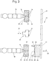
- the Fig. 3 to 9 show different devices for producing a printed plastic article such as the closing strip 10th
- the in the Fig. 3 to 5 shown apparatus has two adjacent to each other, in particular parallel to each other, arranged injection molding machines 18, 19. It is preferably the same injection molding machines 18. Between the injection molding machines 18 and 19, a digital printing device 20 shown only symbolically in the figures is arranged.
- the injection molding machines 18 and 19 and also the digital printing device 20 are at least with their base frame or feet ortsunver sectionlich arranged in exactly fixed, relative positions relative to each other.
- a print head 21 or, if appropriate, also a plurality of print heads of the digital printing device 20 can be moved back and forth during the digital printing process on at least one fixed and also spatially variable axis, which in the exemplary embodiment shown is a straight linear axis.
- Each injection molding machine 18, 19 is assigned its own mold half 22 and 23 fixed.
- the mold halves 22, 23 represent mold-side mold halves 22, 23.
- the mold-side mold halves 22, 23 are designed differently.
- a nozzle tip 24 of each injection molding machine 18, 19 opens in a schematic only in the Fig. 3 to 5 This can be realized in different ways, depending on how the sprue of the plastic object to be produced is designed and / or which sprue is used.
- each injection molding machine 18 or 19 is formed by a second mold half, which is preferably an ejector-side mold half 26.
- the apparatus has a single ejector side mold half 26 which forms part of the mold of the injection molding machine 18 and 19.
- the mold half 26 is a schematic only in the Fig. 3 to 5 assigned transfer device 27 assigned. This serves to move the mold half 26 assigned to it back and forth according to the shuttle principle between the injection molding machines 18, 19 and thereby to the digital printing device 20 arranged therebetween. Thus, the mold half 26 alternately forms one half each of the mold of the injection molding machine 18 and the injection molding machine 19.
- the mold half 26 movable by the transfer device 27 also serves to lubricate the carrier layer 11 injected by the injection molding machine 18 in the mold half 26 or any other part of the article Plastic object position accurately to the digital printing device 20 to transport and the plastic article, in particular the carrier layer 11, in digital printing absolutely free of play and placetsunver selectedlich in a fixed relative position to the digital printing device 20 to keep.
- the mold half 26 is provided in the embodiment shown with two identical nests 28 with the contour of each of a carrier layer 11 or another part of the printed plastic article to be produced.
- a sprue 29 passes from the plasticizing unit of the injection molding machine 18 plasticized plastic via the Anspritzkanal 23 in the mold half 22 in the runner 29 and from there into the two opposite nests 28 to form a respective carrier layer 11.
- the same nests 28 are so in the mold half 26 arranged so that the front side 14 to be printed on the carrier layer 11 is flush with a parting plane 30 of the mold half 26.
- the carrier layer 11 is formed partially in the casting-side mold half 22 in front of the injection molding machine 18.
- the respective carrier layer 11 is partially formed in the sprue-side mold half 22 and partially in the ejector-side mold half 26, wherein preferably a larger part of the carrier layer 11 is injected in the ejector-side mold half 26, so that upon injection of the mold, the sprayed carrier layer 11 in the ejector side mold half remains.
- the forms are shown in the open state.
- the ejector-side mold half 26 is somewhat moved away from the sprue-side mold half 22, so the mold halves 22 and 26 of the mold pulled apart.
- the sprue side mold halves 22 and 23 guide holes 31 or guide sleeves, while the ejector side mold half 26 is provided with respect to the parting line 30 above guide columns 32.
- the guide columns 32 on the respective casting-side mold half 22 and 23 respectively. Then, the guide holes 31 and guide sleeves of the ejector-side mold half 26 are assigned.
- the transfer device 27 has at least one linear, linear traverse and guide axis 33. Along this traverse and guide axis 33, the mold half 26 can be moved from the injection molding machine 18 to the digital printing device 20 and further to the injection molding machine 19. At the injection molding machine 19, the closing strip 10 is provided with the cover layer 16. For this purpose, in the sprue-side mold half 23 in front of the injection molding machine 19, two nests 34 for each cover layer 16 or other parts of the plastic article to be produced are arranged. The nests 34 for the cover layers 16 are for the purpose of better illustration in the Fig. 3 to 5 represented larger than in the Fig. 2 shown. Alternatively, the transfer device can also be formed by at least one robot, in particular handling robot.
- the transfer device 27 has at least in the area of the digital printing device 20 not shown positioning and locking means. These serve to exactly stop the transport of the mold half 26 along the transfer device 27 in a specific relative position to the digital printing device 20, in particular the at least one print head 21 thereof, and thus to position and also the mold half 26 in the position predetermined by the transfer device 27 during of digital printing backlash too fix.
- a base of the digital printing device 20 has guide sleeves or guide holes which correspond to the guide columns 32 of the mold half 26 so that the digital printing device 20 occupies exactly the same position for the mold half 26 in digital printing, which in the production of the carrier layer 11, the mold half 26 to the mold half 22 has held and the at least one print head 21 without play on at least one fixed linear axis relative to the base of the digital printing device 20 is movable.
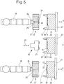
- the Fig. 6 shows another embodiment of the device. This differs from the device described above only in that the transfer device 35 is designed for circulating further transport of the mold halves 36 and not only a single ejector side mold half 36 is provided, but at least three same ejector side mold halves 36. At least three ejector side same mold halves 36 according to of the Fig. 6 Each station is assigned a mold half 36, namely each injection molding machine 18 and 19 and the digital printing device 20. This allows both injection molding machines 18 and 19 and the digital printing device 20 to operate continuously.
- the three same ejector side mold halves 36 of Fig. 6 are each formed the same as the mold half 26 of the embodiment of Fig. 3 to 5 ,
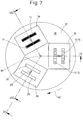
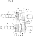
- the Fig. 7 and 8th show a device according to another embodiment of the invention. This differs from the embodiment of Fig. 6 only in that instead of the mold halves 36 further linearly transporting transfer device 35 in the device of Fig. 7 to 9 a trained as a turntable 37 transfer device is provided.
- the turntable 37 has a circular in the embodiment shown receiving plate 38 which is rotatable clockwise about a central vertical or horizontal axis of rotation 39 clockwise.
- the receiving plate 38 of the transfer device are assigned three identically designed ejector-side mold halves 36, with an angular offset of 120 °.
- the two injection molding machines 18 and 19 and the digital printing device 20 in the apparatus shown here are mounted on a pitch circle corresponding to the pitch circle on which the mold halves 36 are on the turntable 37.
- the pitch circle On the pitch circle the injection molding machines 18 and 19 and the digital printing device 20 as well as the three mold halves 36 are arranged on the turntable 37 with an equal angular offset of 120 °.
- the carrier layer 11 is injected in the mold half 26 in the closed mold.
- the front side 14 of the carrier layer 11 to be printed lies in the parting plane 30 of the mold half 26 or somewhat before, when a part of the carrier layer 11 is also formed in the mold half 22.
- the mold half 26 is transported by the transfer device 27 in the transfer direction 42 to the digital printing device 20.
- the mold half 26 preferably passes through a cooling section so that the cooled carrier layer 11 remaining in the mold half 26 moves from the mold half 26 into a predetermined relative position relative to the digital printing device 20 is brought.
- This predetermined relative position is matched to the positioning of the print 15 to be produced by the digital printing device 20 on the front side 14 of the carrier layer 11.
- the mold half 26 is then fixed free of play with the two carrier layers 11 still located in the nests 28 of the transfer device 27 on the transfer device 27. This fixation or determination of the mold half 26 with the carrier layers 11 therein remains unchanged during the digital printing operation, at least during the operation of the digital printing device 20 for the production of the printing 15.
- the printing device 20 is guided on the traverse and guide axis linear play so close to the parting plane 30 and thus the printed front sides 14 of the carrier layers 11 moved up that the digital printing can take place.
- the two separate print heads 21 for a carrier layer 11 are synchronously together via another linear path perpendicular to the plane of the drawing (FIG. Fig. 3 ).
- the digital printing device 20 with the two print heads 21, but possibly also only one print head 21, can be moved back and forth several times on the web extending perpendicular to the plane of the drawing.
- the digital printing device 20 is moved back again on its traversing and guiding axis, that is, it is again spaced from the mold half 26. Then, if necessary, after releasing the positionally accurate locking of the mold half 26 before or next to the digital printing device 20 of the transfer device 27, the mold half 26 with the two printed carrier layers 11 by another clock in the transfer direction 42 moves before the second injection molding machine 19 associated mold half 23.
- the mold is closed in front of the injection molding machine 19.
- the cover layer 16 is then sprayed onto the front side 14 of the respective carrier layer 11 provided with the printing 15 in the nests 34 of the mold half 23.
- the imprints 15 between the two simultaneously formed outer layers 16 and the previously produced carrier layers 11 are embedded and there is a connection to the carrier layers 11 or their printing 15 and the outer layers 16.
- the mold is raised and the two finished closing strips 10 are ejected preferably by an ejector system in the mold half 26.
- this is transported back by the transfer device 27, namely the inactive digital printing device 20 past the mold half 22 of the first injection molding machine 18 and by approaching the mold half 26 to the mold half 22, the shape of the Injection molding machine 18 closed. It then begins the procedure described above for producing the next two printed closing strips 10th
- Fig. 6 to 9 operate on the principle of the same procedure as the device described above.
- two support layers 11, which are produced simultaneously by the injection molding machine 18, with the mold half 26 are moved by the transfer device 27 in front of the digital printing device 20 and positioned here.
- the main difference with the device of the 4 to 6 performed method for the method according to Fig. 3 is that by using three identical ejector-side mold halves 26 in the production of the carrier layers 11 in one mold half 26, the carrier layers 11 are printed simultaneously in the other mold half 26 and at the same time in the third mold half 26, the cover layers 16 on the carrier layers 11 and Prints 15 on the front sides 14 of the same of the second injection molding machine 19 are injected.
- the injection molding machines 18, 19 and the digital printing device 20 do not need to wait until the two closing strips 10 are completed. Instead, the injection molding machines 18 and 19 as well as the digital printing device 20 operate simultaneously at each cycle of the transfer device 27, ie after each simultaneous movement of all three mold halves 26.
- mold half 26 After completing two closing strips 10 on the rear injection molding machine 19 and ejecting the finished closing strips 10 from the currently assigned to the rear injection molding machine 19 of the transfer device 27 mold half 26 is the empty rear mold half 26 along a circumferential path of the transfer device 27, for example, in the Fig. 6 shown three mold halves 26 away, transported back to the first, front injection molding machine 18 with the mold half 22nd
- the in the Fig. 7 to 9 shown device operates in principle by the same method as the device of Fig. 6 , Only here does not transport transfer means 35, the mold halves 36 on a straight line on injection molding machines 18, 19 of the digital printing device 20 over, but on a rotating, closed circular path, in the direction of rotation 43. Accordingly, the transfer device of Fig. 7 to 9 a turntable 37, which is driven cyclically around a central axis of rotation 39 in the direction of rotation 43. On one of the circular path corresponding pitch circle here the three identically designed ejector side mold halves 36 are arranged with an angular offset by 120 °.
- the three same mold halves 36 also allow simultaneous operation of the injection molding machines 18, 19 of the digital printing device 20 after each cyclic rotation of the turntable by 120 °. It can therefore also in the device of Fig. 7 to 9 the injection molding machines 18, 19 and the digital printing device 20 are operated simultaneously, simultaneously or synchronously.
- the advantage of the device Fig. 7 to 9 opposite the device of Fig. 6 consists in that the transfer system does not require a return line for returning the empty mold halves from the second injection molding machine 19 to the first injection molding machine 18. The transfer paths are thereby shorter, which can lead to a corresponding reduction of the cycle times.
- a rotary shaft 40 for cyclically rotating drive of the turntable 37 by 120 ° telescopically, for example, as a propeller shaft, is formed.
- the embodiments of the invention described above relate to molds with two nests 28, 34 in the mold halves 22, 23, 26 and 36.
- the invention is not limited thereto.
- the invention is also suitable for devices with molds which have only one nester or more than two nests.
- the invention is also suitable for plastic articles of any kind and design, so it is not limited to the described closing strip 10.
- the invention is not limited to a closing strip 10 with a carrier layer 11 and a cover layer 16.
- the invention is also suitable for printed plastic articles in which the printing is covered with no sprayed, transparent cover layer.
Landscapes
- Engineering & Computer Science (AREA)
- Manufacturing & Machinery (AREA)
- Mechanical Engineering (AREA)
- Injection Moulding Of Plastics Or The Like (AREA)
- Moulds For Moulding Plastics Or The Like (AREA)
Claims (11)
- Procédé de fabrication d'un objet en plastique imprimé, dans lequel on produit une couche de support projetée (11) par moulage par injection et on munit un côté de la couche de support (11) d'au moins une impression (15), dans lequel on munit la couche de support (11) de ladite au moins une impression (15) dans le moule ou le demi-moule (26, 36) dans lequel elle a été produite, caractérisé en ce que l'on exécute ladite au moins une impression (15) de la couche de support (11) par au moins une impression numérique.
- Procédé selon la revendication 1, caractérisé en ce qu'après l'impression on projette une couche de recouvrement au moins partiellement transparente (16) sur le côté libre visible de ladite au moins une impression (15) .
- Procédé selon la revendication 1 ou 2, caractérisé en ce que l'on réalise ladite au moins une impression (15) de la couche de support (11) avec le moule ou le demi-moule ouvert (26, 36), de préférence on munit de ladite au moins une impression (15) le côté de la couche de support (11) restant dans le moule ou le demi-moule ouvert (26, 36), qui est libre dans le demi-moule concerné (26, 36) lorsque le moule est ouvert.
- Procédé selon l'une quelconque des revendications 1 à 3, caractérisé en ce que l'on moule par injection la couche de support (11) au moins en majeure partie dans un demi-moule (26, 36), de préférence dans un demi-moule du côté éjecteur (26, 36).
- Procédé selon l'une quelconque des revendications 1 à 4, caractérisé en ce que l'on munit le côté à imprimer de la couche de support projetée (11) d'au moins un revêtement ou d'une couche intermédiaire, de préférence d'une couche de couleur, et on applique ensuite sur le revêtement ou la couche intermédiaire ou la couche de couleur ladite au moins une impression (15) par impression numérique.
- Procédé selon l'une quelconque des revendications 1 à 5, caractérisé en ce que la couche de support (15) reste jusqu'après le moulage par injection de la couche de recouvrement (16) dans le demi-moule (26, 36), dans lequel elle a été injectée et/ou on forme le moule pour l'injection de la couche de recouvrement (16) avec le demi-moule (26, 36), dans lequel la couche de support (11) a été injectée.
- Procédé selon l'une quelconque des revendications 1 à 6, caractérisé en ce que l'on n'éjecte l'objet en plastique de préférence complètement imprimé avec le moule ouvert hors du demi-moule (26, 36) dans lequel ladite au moins une couche de support (11) a été injectée et ladite au moins une impression (15) a été appliquée sur la couche de support (11), qu'après avoir effectué l'injection de la couche de recouvrement (16).
- Dispositif de fabrication d'un objet en plastique imprimé avec au moins une machine de moulage par injection (18, 19) et au moins un moule pour le moulage par injection d'au moins une couche de support (11) de l'objet, un dispositif d'impression constitué par un dispositif d'impression numérique (20) pour l'impression de l'objet en plastique, et un dispositif de transfert (27, 35), caractérisé en ce que le dispositif de transfert (27, 35) est prévu pour au moins un demi-moule (26, 36) du moule formant ou contenant la couche de support (11) et/ou le dispositif d'impression numérique (20), et le dispositif de transfert (27, 35) est configuré pour le transfert du demi-moule (26, 36) avec ladite au moins une couche de support (11) s'y trouvant encore vers le dispositif d'impression numérique (20) et pour le retour du demi-moule concerné (26, 36).
- Dispositif selon la revendication 8, caractérisé en ce que le dispositif de transfert (27, 35) présente des moyens pour positionner, orienter et/ou arrêter le demi-moule (26, 36) par rapport au dispositif d'impression numérique (20) et/ou le dispositif de transfert (27, 35) est configuré pour transporter le demi-moule (26, 36) formant ladite au moins une couche de support (11), de préférence le demi-moule côté éjecteur (26, 36), de façon réciproque entre les machines de moulage par injection (18, 19) et ainsi transporter le demi-moule (26, 36) vers le dispositif d'impression numérique (20) et l'y positionner et/ou l'y immobiliser.
- Dispositif selon la revendication 8 ou 9, caractérisé par deux machines de moulage par injection (18, 19), entre lesquelles le dispositif d'impression numérique (20) est disposé ou le dispositif d'impression numérique (20) est associé à une machine de moulage par injection (18, 19).
- Dispositif selon l'une quelconque des revendications 8 à 10, caractérisé en ce que le demi-moule (26, 36) pour la formation de ladite au moins une couche de support (11), de préférence le demi-moule côté éjecteur (26, 36), forme une partie du moule de chaque machine de moulage par injection (18, 19) et une autre partie du moule de chaque machine de moulage par injection (18, 19) est formée par un demi-moule spécial (22, 23), de préférence un demi-moule spécial côté amorce de coulée (22, 23), de préférence un demi-moule (22, 23) associé en permanence à la machine de moulage par injection respective (18, 19) pour le moulage par injection d'une couche de recouvrement (16) de l'objet en plastique imprimé.
Applications Claiming Priority (1)
| Application Number | Priority Date | Filing Date | Title |
|---|---|---|---|
| DE102016001805.4A DE102016001805A1 (de) | 2016-02-17 | 2016-02-17 | Bedruckter Kunststoffgegenstand sowie Verfahren und Vorrichtung zur Herstellung desselben |
Publications (3)
| Publication Number | Publication Date |
|---|---|
| EP3208097A2 EP3208097A2 (fr) | 2017-08-23 |
| EP3208097A3 EP3208097A3 (fr) | 2017-11-08 |
| EP3208097B1 true EP3208097B1 (fr) | 2019-01-02 |
Family
ID=58098390
Family Applications (1)
| Application Number | Title | Priority Date | Filing Date |
|---|---|---|---|
| EP17000196.0A Not-in-force EP3208097B1 (fr) | 2016-02-17 | 2017-02-08 | Procédé et dispositif de fabrication d'un objet en plastique imprimé |
Country Status (2)
| Country | Link |
|---|---|
| EP (1) | EP3208097B1 (fr) |
| DE (1) | DE102016001805A1 (fr) |
Families Citing this family (2)
| Publication number | Priority date | Publication date | Assignee | Title |
|---|---|---|---|---|
| CN111391228B (zh) * | 2020-03-20 | 2022-05-13 | 东莞市艾尔玛塑件科技有限公司 | 一种双色注塑设备 |
| DE102022134148A1 (de) | 2022-12-20 | 2024-06-20 | Rehau Automotive Se & Co. Kg | Verfahren zur Herstellung eines wenigstens zwei Farbschichten aufweisenden Bauteils für ein Kraftfahrzeug |
Family Cites Families (18)
| Publication number | Priority date | Publication date | Assignee | Title |
|---|---|---|---|---|
| US5380391A (en) * | 1993-03-08 | 1995-01-10 | Mahn, Jr.; John | Heat activated transfer for elastomeric materials |
| JPH09314568A (ja) * | 1996-03-27 | 1997-12-09 | Toray Ind Inc | 印刷成形品の製造方法および成形金型 |
| SE520827C2 (sv) * | 2000-04-05 | 2003-09-02 | Nolato Ab | Aggregat och metod för framställning av bärare av information eller dekoration |
| GB0213921D0 (en) * | 2002-06-18 | 2002-07-31 | Ici Plc | Improvements in or relating to decoration of plastics articles |
| JP4101840B2 (ja) * | 2003-08-13 | 2008-06-18 | セイコープレシジョン株式会社 | カードの製造方法及びカード製造装置 |
| US20050051920A1 (en) * | 2003-09-04 | 2005-03-10 | Joel Thomson | Methods and devices for in-mold printing on molded parts |
| US8083979B2 (en) * | 2003-12-31 | 2011-12-27 | International Automotive Components Group North America, Inc. | In mold lamination of decorative products |
| TWI248416B (en) * | 2004-03-12 | 2006-02-01 | Hon Hai Prec Ind Co Ltd | Transfer printing method for injection molding process |
| US7210408B2 (en) * | 2004-12-30 | 2007-05-01 | Plastipak Packaging, Inc. | Printing plastic containers with digital images |
| EP2144739B1 (fr) * | 2007-05-01 | 2013-02-13 | Exatec, LLC. | Panneau de vitrage plastique ayant un motif imprimé durcissable aux uv et procédé de fabrication de celui-ci |
| DE102007030307B4 (de) * | 2007-06-29 | 2011-04-28 | Kilian Saueressig | Verfahren zum Herstellen von farbigen, dreidimensional strukturierten Bauteilen mit Freiformflächen |
| DE102007031121B3 (de) * | 2007-06-29 | 2008-09-25 | Schäfer, Konstanze, Dr. | Verfahren zur Fixierung von Digitalbildern in Kunststoffen und fixiertes Digitalbild |
| US20090295037A1 (en) * | 2008-06-02 | 2009-12-03 | Graham Packaging Company, L.P. | System and process for in-mold decoration of an article |
| KR20090128059A (ko) * | 2008-06-10 | 2009-12-15 | 삼성전자주식회사 | 사출성형시스템 및 사출성형방법 |
| DE102008035728B4 (de) * | 2008-07-31 | 2016-02-11 | Continental Automotive Gmbh | Verfahren und Vorrichtung zur Herstellung eines beschichteten Bauteils |
| KR101155175B1 (ko) * | 2010-02-04 | 2012-06-14 | 최화식 | 다중성형품 자동생산이 가능한 사출성형기 및 이를 이용한 다중성형품 제조방법 |
| CN102233641B (zh) * | 2010-05-05 | 2013-11-13 | 光宝电子(广州)有限公司 | 数字显示器的壳体的制造方法 |
| JP2012012019A (ja) * | 2010-06-29 | 2012-01-19 | Yupo Corp | 射出成形複合容器およびその製造方法 |
-
2016
- 2016-02-17 DE DE102016001805.4A patent/DE102016001805A1/de not_active Withdrawn
-
2017
- 2017-02-08 EP EP17000196.0A patent/EP3208097B1/fr not_active Not-in-force
Non-Patent Citations (1)
| Title |
|---|
| None * |
Also Published As
| Publication number | Publication date |
|---|---|
| EP3208097A3 (fr) | 2017-11-08 |
| EP3208097A2 (fr) | 2017-08-23 |
| DE102016001805A1 (de) | 2017-08-17 |
Similar Documents
| Publication | Publication Date | Title |
|---|---|---|
| EP0504571B1 (fr) | Moule pour le moulage par injection de corps de brosse à plusieurs composants | |
| EP2004380B1 (fr) | Procede et dispositif de fabrication de pieces moulees en matiere synthetique a plusieurs composants | |
| DE3620175C2 (fr) | ||
| DE69826526T2 (de) | Verfahren und gerät zum formen eines zusammengesetzten gegenstands | |
| DE69212895T3 (de) | Spritzgiessverfahren, Vorrichtung und spritzgegossenes Teil | |
| WO2014161014A1 (fr) | Procédé et dispositif pour la fabrication d'une pièce multicouche moulée par injection avec refroidissement intermédiaire | |
| DE1479586B1 (de) | Spritzgiessmaschine mit mehreren Stationen zur Herstellung von aus mehreren Schichten oder Teilen zusammengesetzten Gegenstaenden | |
| EP0495219A2 (fr) | Procédé et dispositif pour fabriquer des objets moulés stratifiés | |
| EP1174242A2 (fr) | Procédé et dispositif pour mouler par injection des articles en matière plastique à plusieurs composants | |
| EP3208097B1 (fr) | Procédé et dispositif de fabrication d'un objet en plastique imprimé | |
| DE102014011135B4 (de) | Verfahren und Vorrichtung zur Herstellung eines Dekorteils | |
| DE102012008939A1 (de) | Spritzgießmaschine | |
| DE102007051701A1 (de) | Vorrichtung und Verfahren zur Herstellung mehrkomponentiger Kunststoff-Formteile | |
| EP1181143B1 (fr) | Procede de production de pieces de plastiques presentant une structure en relief, et dispositif permettant de mettre en oeuvre ce procede | |
| EP0810919B1 (fr) | Machine de moulage par injection | |
| EP0710534B1 (fr) | Procédé et dispositif pour fabriquer des corps de brosse à partir d'au moins deux composants de matière plastique | |
| DE102021121679B3 (de) | Spritzgiessvorrichtung mit drehbaren Kernabschnitten sowie Verfahren zur Herstellung von spritzgegossenen Mehrkomponenten-Kunststoffteilen | |
| EP0794046B1 (fr) | Procédé pour la fabrication de produits en matière plastique à partir de deux composantes, installation et moule à injection pour la réalisation du procédé | |
| DE19722366A1 (de) | Bürstenherstellungsmaschine | |
| DE602005000776T2 (de) | Vorrichtung und Verfahren zum Formen und Zusammenfügen von aus mehreren Komponenten bestehenden Objekten | |
| DE4417986B4 (de) | Bürstenherstellungsmaschine | |
| DE4400649A1 (de) | Bürstenherstellungsmaschine | |
| EP1338398A1 (fr) | Dispositif pour le moulage à plusieurs composants d'objets en matière plastique | |
| DE112009002031T5 (de) | Verzierungsfolie und Verzierungsfolien-Hinterspritzvorrichtung | |
| WO2012045185A1 (fr) | Moule d'injection |
Legal Events
| Date | Code | Title | Description |
|---|---|---|---|
| PUAI | Public reference made under article 153(3) epc to a published international application that has entered the european phase |
Free format text: ORIGINAL CODE: 0009012 |
|
| STAA | Information on the status of an ep patent application or granted ep patent |
Free format text: STATUS: THE APPLICATION HAS BEEN PUBLISHED |
|
| AK | Designated contracting states |
Kind code of ref document: A2 Designated state(s): AL AT BE BG CH CY CZ DE DK EE ES FI FR GB GR HR HU IE IS IT LI LT LU LV MC MK MT NL NO PL PT RO RS SE SI SK SM TR |
|
| AX | Request for extension of the european patent |
Extension state: BA ME |
|
| RIC1 | Information provided on ipc code assigned before grant |
Ipc: B41J 3/407 20060101ALI20170721BHEP Ipc: B41M 7/00 20060101ALN20170721BHEP Ipc: B29C 45/16 20060101ALI20170721BHEP Ipc: B41M 5/00 20060101AFI20170721BHEP |
|
| PUAL | Search report despatched |
Free format text: ORIGINAL CODE: 0009013 |
|
| AK | Designated contracting states |
Kind code of ref document: A3 Designated state(s): AL AT BE BG CH CY CZ DE DK EE ES FI FR GB GR HR HU IE IS IT LI LT LU LV MC MK MT NL NO PL PT RO RS SE SI SK SM TR |
|
| AX | Request for extension of the european patent |
Extension state: BA ME |
|
| RIC1 | Information provided on ipc code assigned before grant |
Ipc: B41J 3/407 20060101ALI20171002BHEP Ipc: B29C 45/16 20060101ALI20171002BHEP Ipc: B41M 5/00 20060101AFI20171002BHEP Ipc: B41M 7/00 20060101ALN20171002BHEP |
|
| STAA | Information on the status of an ep patent application or granted ep patent |
Free format text: STATUS: REQUEST FOR EXAMINATION WAS MADE |
|
| 17P | Request for examination filed |
Effective date: 20180504 |
|
| RBV | Designated contracting states (corrected) |
Designated state(s): AL AT BE BG CH CY CZ DE DK EE ES FI FR GB GR HR HU IE IS IT LI LT LU LV MC MK MT NL NO PL PT RO RS SE SI SK SM TR |
|
| GRAP | Despatch of communication of intention to grant a patent |
Free format text: ORIGINAL CODE: EPIDOSNIGR1 |
|
| STAA | Information on the status of an ep patent application or granted ep patent |
Free format text: STATUS: GRANT OF PATENT IS INTENDED |
|
| RIC1 | Information provided on ipc code assigned before grant |
Ipc: B29C 45/16 20060101ALI20180717BHEP Ipc: B41M 5/00 20060101AFI20180717BHEP Ipc: B41J 3/407 20060101ALI20180717BHEP Ipc: B41M 7/00 20060101ALN20180717BHEP |
|
| INTG | Intention to grant announced |
Effective date: 20180815 |
|
| GRAS | Grant fee paid |
Free format text: ORIGINAL CODE: EPIDOSNIGR3 |
|
| GRAA | (expected) grant |
Free format text: ORIGINAL CODE: 0009210 |
|
| STAA | Information on the status of an ep patent application or granted ep patent |
Free format text: STATUS: THE PATENT HAS BEEN GRANTED |
|
| AK | Designated contracting states |
Kind code of ref document: B1 Designated state(s): AL AT BE BG CH CY CZ DE DK EE ES FI FR GB GR HR HU IE IS IT LI LT LU LV MC MK MT NL NO PL PT RO RS SE SI SK SM TR |
|
| REG | Reference to a national code |
Ref country code: GB Ref legal event code: FG4D Free format text: NOT ENGLISH |
|
| REG | Reference to a national code |
Ref country code: CH Ref legal event code: EP Ref country code: AT Ref legal event code: REF Ref document number: 1083868 Country of ref document: AT Kind code of ref document: T Effective date: 20190115 |
|
| REG | Reference to a national code |
Ref country code: IE Ref legal event code: FG4D Free format text: LANGUAGE OF EP DOCUMENT: GERMAN |
|
| REG | Reference to a national code |
Ref country code: DE Ref legal event code: R096 Ref document number: 502017000565 Country of ref document: DE |
|
| PGFP | Annual fee paid to national office [announced via postgrant information from national office to epo] |
Ref country code: LU Payment date: 20190208 Year of fee payment: 3 |
|
| REG | Reference to a national code |
Ref country code: NL Ref legal event code: MP Effective date: 20190102 |
|
| REG | Reference to a national code |
Ref country code: LT Ref legal event code: MG4D |
|
| PGFP | Annual fee paid to national office [announced via postgrant information from national office to epo] |
Ref country code: BE Payment date: 20190215 Year of fee payment: 3 |
|
| PG25 | Lapsed in a contracting state [announced via postgrant information from national office to epo] |
Ref country code: NL Free format text: LAPSE BECAUSE OF FAILURE TO SUBMIT A TRANSLATION OF THE DESCRIPTION OR TO PAY THE FEE WITHIN THE PRESCRIBED TIME-LIMIT Effective date: 20190102 |
|
| PG25 | Lapsed in a contracting state [announced via postgrant information from national office to epo] |
Ref country code: FI Free format text: LAPSE BECAUSE OF FAILURE TO SUBMIT A TRANSLATION OF THE DESCRIPTION OR TO PAY THE FEE WITHIN THE PRESCRIBED TIME-LIMIT Effective date: 20190102 Ref country code: PL Free format text: LAPSE BECAUSE OF FAILURE TO SUBMIT A TRANSLATION OF THE DESCRIPTION OR TO PAY THE FEE WITHIN THE PRESCRIBED TIME-LIMIT Effective date: 20190102 Ref country code: PT Free format text: LAPSE BECAUSE OF FAILURE TO SUBMIT A TRANSLATION OF THE DESCRIPTION OR TO PAY THE FEE WITHIN THE PRESCRIBED TIME-LIMIT Effective date: 20190502 Ref country code: NO Free format text: LAPSE BECAUSE OF FAILURE TO SUBMIT A TRANSLATION OF THE DESCRIPTION OR TO PAY THE FEE WITHIN THE PRESCRIBED TIME-LIMIT Effective date: 20190402 Ref country code: SE Free format text: LAPSE BECAUSE OF FAILURE TO SUBMIT A TRANSLATION OF THE DESCRIPTION OR TO PAY THE FEE WITHIN THE PRESCRIBED TIME-LIMIT Effective date: 20190102 Ref country code: ES Free format text: LAPSE BECAUSE OF FAILURE TO SUBMIT A TRANSLATION OF THE DESCRIPTION OR TO PAY THE FEE WITHIN THE PRESCRIBED TIME-LIMIT Effective date: 20190102 Ref country code: LT Free format text: LAPSE BECAUSE OF FAILURE TO SUBMIT A TRANSLATION OF THE DESCRIPTION OR TO PAY THE FEE WITHIN THE PRESCRIBED TIME-LIMIT Effective date: 20190102 |
|
| PG25 | Lapsed in a contracting state [announced via postgrant information from national office to epo] |
Ref country code: LV Free format text: LAPSE BECAUSE OF FAILURE TO SUBMIT A TRANSLATION OF THE DESCRIPTION OR TO PAY THE FEE WITHIN THE PRESCRIBED TIME-LIMIT Effective date: 20190102 Ref country code: RS Free format text: LAPSE BECAUSE OF FAILURE TO SUBMIT A TRANSLATION OF THE DESCRIPTION OR TO PAY THE FEE WITHIN THE PRESCRIBED TIME-LIMIT Effective date: 20190102 Ref country code: HR Free format text: LAPSE BECAUSE OF FAILURE TO SUBMIT A TRANSLATION OF THE DESCRIPTION OR TO PAY THE FEE WITHIN THE PRESCRIBED TIME-LIMIT Effective date: 20190102 Ref country code: BG Free format text: LAPSE BECAUSE OF FAILURE TO SUBMIT A TRANSLATION OF THE DESCRIPTION OR TO PAY THE FEE WITHIN THE PRESCRIBED TIME-LIMIT Effective date: 20190402 Ref country code: GR Free format text: LAPSE BECAUSE OF FAILURE TO SUBMIT A TRANSLATION OF THE DESCRIPTION OR TO PAY THE FEE WITHIN THE PRESCRIBED TIME-LIMIT Effective date: 20190403 Ref country code: IS Free format text: LAPSE BECAUSE OF FAILURE TO SUBMIT A TRANSLATION OF THE DESCRIPTION OR TO PAY THE FEE WITHIN THE PRESCRIBED TIME-LIMIT Effective date: 20190502 |
|
| REG | Reference to a national code |
Ref country code: DE Ref legal event code: R097 Ref document number: 502017000565 Country of ref document: DE |
|
| PG25 | Lapsed in a contracting state [announced via postgrant information from national office to epo] |
Ref country code: DK Free format text: LAPSE BECAUSE OF FAILURE TO SUBMIT A TRANSLATION OF THE DESCRIPTION OR TO PAY THE FEE WITHIN THE PRESCRIBED TIME-LIMIT Effective date: 20190102 Ref country code: EE Free format text: LAPSE BECAUSE OF FAILURE TO SUBMIT A TRANSLATION OF THE DESCRIPTION OR TO PAY THE FEE WITHIN THE PRESCRIBED TIME-LIMIT Effective date: 20190102 Ref country code: IT Free format text: LAPSE BECAUSE OF FAILURE TO SUBMIT A TRANSLATION OF THE DESCRIPTION OR TO PAY THE FEE WITHIN THE PRESCRIBED TIME-LIMIT Effective date: 20190102 Ref country code: CZ Free format text: LAPSE BECAUSE OF FAILURE TO SUBMIT A TRANSLATION OF THE DESCRIPTION OR TO PAY THE FEE WITHIN THE PRESCRIBED TIME-LIMIT Effective date: 20190102 Ref country code: SK Free format text: LAPSE BECAUSE OF FAILURE TO SUBMIT A TRANSLATION OF THE DESCRIPTION OR TO PAY THE FEE WITHIN THE PRESCRIBED TIME-LIMIT Effective date: 20190102 Ref country code: RO Free format text: LAPSE BECAUSE OF FAILURE TO SUBMIT A TRANSLATION OF THE DESCRIPTION OR TO PAY THE FEE WITHIN THE PRESCRIBED TIME-LIMIT Effective date: 20190102 Ref country code: AL Free format text: LAPSE BECAUSE OF FAILURE TO SUBMIT A TRANSLATION OF THE DESCRIPTION OR TO PAY THE FEE WITHIN THE PRESCRIBED TIME-LIMIT Effective date: 20190102 Ref country code: MC Free format text: LAPSE BECAUSE OF FAILURE TO SUBMIT A TRANSLATION OF THE DESCRIPTION OR TO PAY THE FEE WITHIN THE PRESCRIBED TIME-LIMIT Effective date: 20190102 |
|
| PLBE | No opposition filed within time limit |
Free format text: ORIGINAL CODE: 0009261 |
|
| STAA | Information on the status of an ep patent application or granted ep patent |
Free format text: STATUS: NO OPPOSITION FILED WITHIN TIME LIMIT |
|
| REG | Reference to a national code |
Ref country code: IE Ref legal event code: MM4A |
|
| PG25 | Lapsed in a contracting state [announced via postgrant information from national office to epo] |
Ref country code: SM Free format text: LAPSE BECAUSE OF FAILURE TO SUBMIT A TRANSLATION OF THE DESCRIPTION OR TO PAY THE FEE WITHIN THE PRESCRIBED TIME-LIMIT Effective date: 20190102 |
|
| 26N | No opposition filed |
Effective date: 20191003 |
|
| PG25 | Lapsed in a contracting state [announced via postgrant information from national office to epo] |
Ref country code: IE Free format text: LAPSE BECAUSE OF NON-PAYMENT OF DUE FEES Effective date: 20190208 |
|
| PG25 | Lapsed in a contracting state [announced via postgrant information from national office to epo] |
Ref country code: SI Free format text: LAPSE BECAUSE OF FAILURE TO SUBMIT A TRANSLATION OF THE DESCRIPTION OR TO PAY THE FEE WITHIN THE PRESCRIBED TIME-LIMIT Effective date: 20190102 Ref country code: FR Free format text: LAPSE BECAUSE OF NON-PAYMENT OF DUE FEES Effective date: 20190302 |
|
| PG25 | Lapsed in a contracting state [announced via postgrant information from national office to epo] |
Ref country code: TR Free format text: LAPSE BECAUSE OF FAILURE TO SUBMIT A TRANSLATION OF THE DESCRIPTION OR TO PAY THE FEE WITHIN THE PRESCRIBED TIME-LIMIT Effective date: 20190102 |
|
| PGFP | Annual fee paid to national office [announced via postgrant information from national office to epo] |
Ref country code: DE Payment date: 20200130 Year of fee payment: 4 |
|
| PG25 | Lapsed in a contracting state [announced via postgrant information from national office to epo] |
Ref country code: MT Free format text: LAPSE BECAUSE OF FAILURE TO SUBMIT A TRANSLATION OF THE DESCRIPTION OR TO PAY THE FEE WITHIN THE PRESCRIBED TIME-LIMIT Effective date: 20190102 |
|
| REG | Reference to a national code |
Ref country code: CH Ref legal event code: PL |
|
| REG | Reference to a national code |
Ref country code: BE Ref legal event code: MM Effective date: 20200229 |
|
| PG25 | Lapsed in a contracting state [announced via postgrant information from national office to epo] |
Ref country code: LU Free format text: LAPSE BECAUSE OF NON-PAYMENT OF DUE FEES Effective date: 20200208 |
|
| PG25 | Lapsed in a contracting state [announced via postgrant information from national office to epo] |
Ref country code: CH Free format text: LAPSE BECAUSE OF NON-PAYMENT OF DUE FEES Effective date: 20200229 Ref country code: LI Free format text: LAPSE BECAUSE OF NON-PAYMENT OF DUE FEES Effective date: 20200229 |
|
| PG25 | Lapsed in a contracting state [announced via postgrant information from national office to epo] |
Ref country code: BE Free format text: LAPSE BECAUSE OF NON-PAYMENT OF DUE FEES Effective date: 20200229 |
|
| PG25 | Lapsed in a contracting state [announced via postgrant information from national office to epo] |
Ref country code: CY Free format text: LAPSE BECAUSE OF FAILURE TO SUBMIT A TRANSLATION OF THE DESCRIPTION OR TO PAY THE FEE WITHIN THE PRESCRIBED TIME-LIMIT Effective date: 20190102 |
|
| PG25 | Lapsed in a contracting state [announced via postgrant information from national office to epo] |
Ref country code: HU Free format text: LAPSE BECAUSE OF FAILURE TO SUBMIT A TRANSLATION OF THE DESCRIPTION OR TO PAY THE FEE WITHIN THE PRESCRIBED TIME-LIMIT; INVALID AB INITIO Effective date: 20170208 |
|
| REG | Reference to a national code |
Ref country code: DE Ref legal event code: R119 Ref document number: 502017000565 Country of ref document: DE |
|
| GBPC | Gb: european patent ceased through non-payment of renewal fee |
Effective date: 20210208 |
|
| PG25 | Lapsed in a contracting state [announced via postgrant information from national office to epo] |
Ref country code: DE Free format text: LAPSE BECAUSE OF NON-PAYMENT OF DUE FEES Effective date: 20210901 Ref country code: GB Free format text: LAPSE BECAUSE OF NON-PAYMENT OF DUE FEES Effective date: 20210208 |
|
| PG25 | Lapsed in a contracting state [announced via postgrant information from national office to epo] |
Ref country code: MK Free format text: LAPSE BECAUSE OF FAILURE TO SUBMIT A TRANSLATION OF THE DESCRIPTION OR TO PAY THE FEE WITHIN THE PRESCRIBED TIME-LIMIT Effective date: 20190102 |
|
| REG | Reference to a national code |
Ref country code: AT Ref legal event code: MM01 Ref document number: 1083868 Country of ref document: AT Kind code of ref document: T Effective date: 20220208 |
|
| PG25 | Lapsed in a contracting state [announced via postgrant information from national office to epo] |
Ref country code: AT Free format text: LAPSE BECAUSE OF NON-PAYMENT OF DUE FEES Effective date: 20220208 |