EP3208038B2 - Manual separation device - Google Patents
Manual separation device Download PDFInfo
- Publication number
- EP3208038B2 EP3208038B2 EP17164894.2A EP17164894A EP3208038B2 EP 3208038 B2 EP3208038 B2 EP 3208038B2 EP 17164894 A EP17164894 A EP 17164894A EP 3208038 B2 EP3208038 B2 EP 3208038B2
- Authority
- EP
- European Patent Office
- Prior art keywords
- covering
- cutting tool
- hand
- side edge
- covering element
- Prior art date
- Legal status (The legal status is an assumption and is not a legal conclusion. Google has not performed a legal analysis and makes no representation as to the accuracy of the status listed.)
- Active
Links
- 238000000926 separation method Methods 0.000 title 1
- 239000000428 dust Substances 0.000 claims description 13
- 238000000605 extraction Methods 0.000 claims description 7
- 239000012780 transparent material Substances 0.000 claims description 4
- 238000011144 upstream manufacturing Methods 0.000 claims description 2
- 238000007689 inspection Methods 0.000 claims 1
- 230000000149 penetrating effect Effects 0.000 claims 1
- 230000000284 resting effect Effects 0.000 description 6
- 230000035515 penetration Effects 0.000 description 4
- 208000027418 Wounds and injury Diseases 0.000 description 3
- 230000006378 damage Effects 0.000 description 3
- 208000014674 injury Diseases 0.000 description 3
- 239000002245 particle Substances 0.000 description 3
- 230000002093 peripheral effect Effects 0.000 description 2
- 229920003023 plastic Polymers 0.000 description 2
- 238000011161 development Methods 0.000 description 1
- 230000018109 developmental process Effects 0.000 description 1
- 238000004146 energy storage Methods 0.000 description 1
- 230000002349 favourable effect Effects 0.000 description 1
- 210000003811 finger Anatomy 0.000 description 1
- 210000004247 hand Anatomy 0.000 description 1
- 239000000463 material Substances 0.000 description 1
- 239000002184 metal Substances 0.000 description 1
- 239000004575 stone Substances 0.000 description 1
- 210000003813 thumb Anatomy 0.000 description 1
Images


Classifications
-
- B—PERFORMING OPERATIONS; TRANSPORTING
- B24—GRINDING; POLISHING
- B24B—MACHINES, DEVICES, OR PROCESSES FOR GRINDING OR POLISHING; DRESSING OR CONDITIONING OF ABRADING SURFACES; FEEDING OF GRINDING, POLISHING, OR LAPPING AGENTS
- B24B27/00—Other grinding machines or devices
- B24B27/06—Grinders for cutting-off
- B24B27/08—Grinders for cutting-off being portable
-
- B—PERFORMING OPERATIONS; TRANSPORTING
- B23—MACHINE TOOLS; METAL-WORKING NOT OTHERWISE PROVIDED FOR
- B23D—PLANING; SLOTTING; SHEARING; BROACHING; SAWING; FILING; SCRAPING; LIKE OPERATIONS FOR WORKING METAL BY REMOVING MATERIAL, NOT OTHERWISE PROVIDED FOR
- B23D59/00—Accessories specially designed for sawing machines or sawing devices
- B23D59/006—Accessories specially designed for sawing machines or sawing devices for removing or collecting chips
-
- B—PERFORMING OPERATIONS; TRANSPORTING
- B23—MACHINE TOOLS; METAL-WORKING NOT OTHERWISE PROVIDED FOR
- B23Q—DETAILS, COMPONENTS, OR ACCESSORIES FOR MACHINE TOOLS, e.g. ARRANGEMENTS FOR COPYING OR CONTROLLING; MACHINE TOOLS IN GENERAL CHARACTERISED BY THE CONSTRUCTION OF PARTICULAR DETAILS OR COMPONENTS; COMBINATIONS OR ASSOCIATIONS OF METAL-WORKING MACHINES, NOT DIRECTED TO A PARTICULAR RESULT
- B23Q11/00—Accessories fitted to machine tools for keeping tools or parts of the machine in good working condition or for cooling work; Safety devices specially combined with or arranged in, or specially adapted for use in connection with, machine tools
- B23Q11/08—Protective coverings for parts of machine tools; Splash guards
- B23Q11/0825—Relatively slidable coverings, e.g. telescopic
- B23Q11/0833—Relatively slidable coverings, e.g. telescopic with a non-rectilinear shifting
-
- B—PERFORMING OPERATIONS; TRANSPORTING
- B24—GRINDING; POLISHING
- B24B—MACHINES, DEVICES, OR PROCESSES FOR GRINDING OR POLISHING; DRESSING OR CONDITIONING OF ABRADING SURFACES; FEEDING OF GRINDING, POLISHING, OR LAPPING AGENTS
- B24B23/00—Portable grinding machines, e.g. hand-guided; Accessories therefor
- B24B23/02—Portable grinding machines, e.g. hand-guided; Accessories therefor with rotating grinding tools; Accessories therefor
- B24B23/028—Angle tools
-
- B—PERFORMING OPERATIONS; TRANSPORTING
- B24—GRINDING; POLISHING
- B24B—MACHINES, DEVICES, OR PROCESSES FOR GRINDING OR POLISHING; DRESSING OR CONDITIONING OF ABRADING SURFACES; FEEDING OF GRINDING, POLISHING, OR LAPPING AGENTS
- B24B55/00—Safety devices for grinding or polishing machines; Accessories fitted to grinding or polishing machines for keeping tools or parts of the machine in good working condition
- B24B55/04—Protective covers for the grinding wheel
- B24B55/05—Protective covers for the grinding wheel specially designed for portable grinding machines
- B24B55/052—Protective covers for the grinding wheel specially designed for portable grinding machines with rotating tools
-
- B—PERFORMING OPERATIONS; TRANSPORTING
- B24—GRINDING; POLISHING
- B24B—MACHINES, DEVICES, OR PROCESSES FOR GRINDING OR POLISHING; DRESSING OR CONDITIONING OF ABRADING SURFACES; FEEDING OF GRINDING, POLISHING, OR LAPPING AGENTS
- B24B55/00—Safety devices for grinding or polishing machines; Accessories fitted to grinding or polishing machines for keeping tools or parts of the machine in good working condition
- B24B55/06—Dust extraction equipment on grinding or polishing machines
- B24B55/10—Dust extraction equipment on grinding or polishing machines specially designed for portable grinding machines, e.g. hand-guided
- B24B55/102—Dust extraction equipment on grinding or polishing machines specially designed for portable grinding machines, e.g. hand-guided with rotating tools
-
- B—PERFORMING OPERATIONS; TRANSPORTING
- B27—WORKING OR PRESERVING WOOD OR SIMILAR MATERIAL; NAILING OR STAPLING MACHINES IN GENERAL
- B27G—ACCESSORY MACHINES OR APPARATUS FOR WORKING WOOD OR SIMILAR MATERIALS; TOOLS FOR WORKING WOOD OR SIMILAR MATERIALS; SAFETY DEVICES FOR WOOD WORKING MACHINES OR TOOLS
- B27G19/00—Safety guards or devices specially adapted for wood saws; Auxiliary devices facilitating proper operation of wood saws
- B27G19/02—Safety guards or devices specially adapted for wood saws; Auxiliary devices facilitating proper operation of wood saws for circular saws
- B27G19/04—Safety guards or devices specially adapted for wood saws; Auxiliary devices facilitating proper operation of wood saws for circular saws for manually-operated power-driven circular saws
Definitions
- the invention relates to a hand-held cutting device that can be operated hands-free, in particular a hand-held cut-off grinder or angle grinder, according to the preamble of claim 1.
- the known covering devices must be dismantled if they get in the way during work. For example, a jam with a flange on which the tool holder is provided must then be solved. However, this is complicated.
- a hand-held cutting device according to the preamble of claim 1 is, for example, in DE 697 29 977 T2 or EP 2 666 592 A1 explained.
- a hand-held cutting device is provided according to the technical teaching of claim 1.
- the cover element is adjustable between the cover position and a maximum open position and at least one open position is provided as an intermediate position between the cover position and the maximum open position.
- the covering device which is designed, for example, in the manner of a hood, is made up of several parts, of which, however, only one part is stationary with respect to the machine housing, namely the side edge cover.
- This can of course also house a large part of the cutting tool or the cutting disk, for example also a front side or flat side.
- the cover element is movable, that is, it can pivot about the tool or rotation axis of the cutting tool or an axis parallel to it and thus release a larger working area of the cutting tool, which is advantageous, for example, for separating cuts in inner corner areas of the work object.
- a suction connection for a dust extraction device is arranged on the cover element.
- the suction connection on the movable cover element is, so to speak, always in place, namely where the dust arises.
- the dust is therefore advantageously extracted directly at its source.
- a direction of rotation of the cutting tool is preferably such that it emerges from the workpiece and rotates in the direction of the suction connection.
- the dust thrown out of the workpiece, so to speak, can advantageously be sucked off directly, namely through the suction connection.
- a suction connection for a dust extraction device for example a vacuum cleaner, is arranged on the movable cover element.
- the suction connection is preferably a nozzle or pipe body to which a suction hose can be connected. This means that items, chips or the like that arise at the work site can be sucked out directly through the covering device.
- connection is arranged on the free end region of the cover element. This is then preferably the front or foremost working area of the cutting tool, i.e. the chips, particles or similar other dirt are sucked out of the work object directly at the exit area of the cutting tool.
- a free space or viewing area remains free between the cutting tool and the movable cover element, so that a scribe line extending frontally in front of the cutting tool in the working direction is visible.
- a viewing window or viewing area is provided laterally between the cutting tool and the cover element.
- the hand-held cutting device is preferably a cut-off grinder, in particular an angle grinder.
- the covering device in particular the movable covering element, is advantageously located on the top of the workpiece or on the top of the workpiece when the hand-held cutting device is in operation.
- the covering device can also be a separate or separable component from the separating device, which can also be defined as follows: Covering device for a hands-free hand-held cutting device, which has a tool holder for a disk-shaped cutting tool for making a separating cut in a work object to be machined and a drive motor arranged in a machine housing for rotating the tool holder about a tool axis, the covering device for covering the cutting tool is provided and can be releasably mounted on the machine housing, in particular a flange section of the tool holder, and comprises a side edge cover which is fixed in place on the machine housing during operation of the separating device for covering a side edge of the separating tool, characterized in that it has a side edge cover relative to the side edge cover about one with the tool axis coaxial or to the tool axis parallel pivot axis between a covering position and at least one open position pivotable cover element for covering a working section of the side edge of the cutting tool protruding in front of the stationary side edge cover
- the cover element can be actuated in the direction of the open position at a free end region that is furthest away from the stationary side edge cover by resting on a contact surface in the working direction, frontally in front of the cover element.
- the covering element can be actuated in the direction of the open position at a free end region that is furthest away from the stationary side edge cover by resting on the work object, in particular on its top side.
- the stationary side edge cover could also be part of the machine housing.
- the contact surface projects, for example, in front of the top of the work object.
- the contact surface can be part of the work object.
- the cover element prefferably be actuated manually over a section from the covering position in the direction of the open position to an intermediate position and then to be actuated from the intermediate position further in the direction of the open position by resting on the work object or on the contact surface located frontally in the working direction .
- a stop surface of the cover element for striking against the work object or the contact surface is expediently already outside a distance between its pivot axis and the work object.
- the cover element expediently abuts on the top of the workpiece or can be actuated in the direction of the open position by resting on the top of the workpiece.
- the cover element abuts on a stop surface which extends frontally in front of the cover element in relation to the working direction.
- this contact surface projects upwards in front of the top or surface of the workpiece, in particular at right angles or at an angle.
- the contact surface can also be referred to as the stop surface.
- the cover element can be opened by abutment or by striking a particularly rectangular inner corner region of the work object.
- a suction connection for a dust extraction device for example a vacuum cleaner, to be expediently arranged on the stationary side edge cover and/or on the movable cover element.
- the drive motor is expediently an electric drive motor.
- the cutting device is designed as a hand-held machine tool.
- the separating device can be operated in a network-connected manner, i.e. it has, for example, a connecting cable for connection to an electrical supply network.
- a variant with battery operation or battery operation is also preferred, i.e. that the separating device has, for example, a battery interface for connecting a battery pack or a battery.
- the stationary side edge cover prefferably covers approximately half of the area of the separating device covered by the covering device, and for the movable covering element to cover the other half of the area of the separating tool covered in the covering position.
- the cover element could also be larger, i.e. that it covers a larger angular range of the cutting tool in the covering position than the stationary side edge cover or, conversely, a smaller cover element could be provided which only covers a smaller peripheral area of the cutting tool than the stationary side edge cover.
- a preferred embodiment of the invention which is particularly advantageous for cuts in inner corner areas, provides that the covering device releases an angular range of approximately or at least 160° in the open position of the covering element. It is particularly preferred if an even larger angular range is free, for example an angular range of approximately 160-180°. An angular range of approximately 190° is particularly preferred. The angular range is related to the axis of rotation of the tool holder or the cutting tool.
- a definition of claim 1 provides that when the cover element is open or the cover element is pivoted completely into the open position, a larger angular range of the outer circumference of the cutting tool is available for penetration into the work object than at least 180 °.
- the cutting tool is at least 10% into an approximately rectangular inner corner area of the work object on both sides. preferably 20% or 30% of the diameter of the cutting tool can penetrate.
- the penetration depth can, for example, be greater on an underside, for example 20-25%, in particular about 22%, while the frontal penetration depth is smaller, for example 10-20%, in particular about 15%.
- the cutting tool is free in the covering position of the covering element, for example an angular range of approximately 45° to 130°, for example 90 up to 120 degrees, especially around 110°.
- the direction of rotation of the cutting tool is designed such that it drives the cutting tool from the cover element towards the stationary side edge cover.
- the cutting tool emerges from the work object at the front, at the free end region of the cover element, where dust extraction then takes place, i.e. the suction connection is arranged.
- the cover element so to speak, moves with the exit area from the cutting tool out of the work object and at the same time the suction connection is always provided at the optimal location, namely at the so-called moving exit area of the cutting tool. This measure is particularly advantageous in connection with the already mentioned separating cut in the inner corner areas of the work object.
- the cover element has, for example, a roller, a sliding surface, a sliding body or the like on the free end region that abuts the work object.
- a stop projection projecting in front of the cover element for striking or resting on the work object is also expediently arranged.
- this free end region or the actuating bodies arranged thereon ensure that the cover element can be conveniently adjusted in the direction of the open position.
- the stop projection can also be designed in the manner of a cantilever.
- a stop surface on the free end region of the cover element or the stop projection which advantageously comprises a sliding surface, a roller or similar other sliding elements or movable elements or is designed as a sliding surface, roller or movable element, is expediently outside a distance between on the one hand the pivot axis of the cover element and on the other hand the work object or a guide surface provided for guidance on the work object, for example a guide table, the hand-held machine tool or the covering device, so that the cover element can be actuated automatically in the direction of the open position by striking the work object or the contact surface located frontally in the working direction.
- the stop surface can exert a torque on the cover element in the direction of the open position.
- the covering element is preferably spring-loaded in the direction of the covering position, for example by a spring arrangement.
- the spring arrangement particularly preferably extends on an inner circumference of the stationary side edge cover.
- the spring arrangement it is also possible for the spring arrangement to comprise a spring which is arranged on the cover element or on the outside of the cover element and is supported on the machine housing or the stationary side edge cover.
- the covering device can expediently be fixed, for which a fixing device is provided.
- the fixing device comprises, for example, a latching device, i.e. a latching projection and a latching receptacle, preferably spring-loaded.
- a clamping device, a pawl or the like can also be used advantageously.
- the fixing device serves to fix the cover element relative to the stationary side edge cover, for example in the covering position or the open position or even the position in between.
- the fixing device is adjustable between a release position that releases the cover element relative to the stationary side edge cover and a fixation position that fixes the cover element relative to the side edge cover.
- a locking latch can be fixed in the corresponding fixing position.
- the latching pawl or other latching device is expediently spring-loaded in the direction of the fixing position, for which a spring arrangement is provided.
- the fixing device is preferably spring-loaded in the direction of the fixing position, i.e. that, for example, a fixing element is loaded by a spring arrangement in the direction of the fixing position.
- the fixing device is expediently adjustable into the fixing position only in the covering position.
- a portion of the cutting tool is preferably free for a cutting cut, that is, it can be inserted into the work object and make cutting cuts there.
- the advantage is that the free end region of the cover element can simultaneously fulfill a guiding function when the fixing device is fixed, i.e. it can be supported on the work object in order to guide the cutting tool for a cutting cut carried out at a constant depth.
- the fixing device can expediently be actuated by a hand actuating element which is movably mounted on a fixed component of the separating device and which, in a position assigned to the release position, projects further in front of the fixed component of the separating device than in the fixing position.
- the fixed component is, for example, a component of the covering device, particularly preferably the stationary side edge cover.
- cover element moves exclusively via a sliding bearing on the stationary side edge cover around a curved path running around the pivot axis, in particular a circular path, is displaceably mounted, i.e. without a pivot bearing close to the tool axis, without a bearing shaft or a bearing pin or the like. There is then no pivot bearing device in the area of the pivot axis.
- pivoting movement of the cover element does not necessarily have to be along a circular path, but can also run along a otherwise curved path.
- the covering device expediently has a mounting opening through which the tool holder is accessible for changing the cutting tool.
- the mounting opening can, for example, be dimensioned such that a fastening nut or the like can be detached or closed for the tool.
- the mounting opening can be designed in the manner of a window.
- the mounting opening has a large area, that is to say that it corresponds to a diameter of the cutting tool.
- the cutting tool can be removed from the cutting device through the mounting opening or mounted on it without having to open another component of the covering device.
- a preferred embodiment provides that the cover element or the stationary side edge cover or both exclusively cover the side edge of the cutting tool. Particularly preferably, only the radially outer edge region of the cutting tool is covered. It is even possible that there is still a distance between the radially outer circumference of the cutting tool and a radially inwardly projecting region of the cover element or the side edge cover or both, which makes dismantling the cutting tool particularly convenient from the tool holder or assembly or to the tool holder enabled.
- An expedient embodiment of the invention provides that the cover element and/or the stationary side edge cover consist entirely or partially of transparent material, for example transparent plastic. This means the operator can clearly see the working area of the cutting tool.
- the movable cover element and/or the stationary side edge cover may consist of non-transparent material, for example metal or a correspondingly colored plastic. It is also conceivable that only partial areas consist of transparent, optically permeable material, that is, for example, the front, free end area of the cover element is transparent, so that the operator can see, for example, an exit area or a working area of the cutting tool, where it comes out of the work object exits or enters the work object.
- the cover element can easily be designed so that an entry area or exit area of the cutting tool is clearly visible.
- the cover element has such a distance from a flat side of the cutting tool, for example approximately 1 cm, 2 cm or 3 cm (intermediate areas are possible), that the exit area or entry area and in particular an area of the work object upstream of the exit area or entry area in the working direction for one The operator can be seen at least obliquely from the flat side of the cutting tool. This means that, for example, a scribe line can be clearly seen.
- One embodiment of the invention can provide that the separating device does not have a guide surface arranged next to the covering device on the machine housing for guiding on a surface, for example a guide rail. For example, there is no guide plate.
- An embodiment of the invention may also provide that a relatively narrow or small guide plate is provided. In one embodiment, this can only be provided on an angle section that is furthest away from the cover element, for example on a free end region, of the stationary side edge cover.
- This guide surface is preferably the only guide surface.
- a further guide surface or the correspondingly larger guide surface may extend next to the machine housing.
- the guide surface preferably forms part of the covering device.
- a guide plate is provided on the stationary side edge cover of the covering device.
- This embodiment of the invention which can also represent an independent invention in connection with the preamble of claim 1, expediently provides that one or more stationary guide surfaces, for example in the manner of a guide plate or several guide plates, are provided on the machine housing.
- the at least one guide surface for example on a guide plate, can be provided on the machine housing itself and/or expediently form a component of the covering device.
- these guide surfaces or the guide surface extend forward in the working direction up to a maximum of an area of the cutting tool that cannot be released by the cover element.
- guide surfaces are only provided up to a maximum of the axis of rotation or tool holder. This means that the cutting device can still be guided conveniently on the surface.
- a separating cut into an inside corner is not hindered by the guide plate or the guide surfaces.
- the tool holder and the covering device are arranged at a free end region of the machine housing.
- the machine housing protrudes from the tool holder or the cutting tool in the manner of an arm.
- the machine housing is preferably designed in the manner of a handle that can be grasped with one hand.
- the machine housing it is also possible for the machine housing to have such a handle, that is to say a handle is provided on the machine housing that cannot otherwise be gripped directly.
- the machine housing is designed in the manner of a holding arm serving as a handle for the cutting tool.
- the operator can, for example, grasp the machine housing with one hand, with the cutting tool and the covering device then being provided, so to speak, on the head or free end region of the machine housing.
- the cutting device is used for a type of pulling cut, i.e. that a front end region of the cutting tool in the working direction cuts into the work object, the cutting tool or cutting plate, so to speak, works through the work object and then at the back, in the area of the stationary Side edge cover emerges from the work object.
- the suction connection is provided at the rear of the stationary part of the covering device, namely in the area of the stationary side edge cover.
- the reverse working direction is particularly preferred, i.e. that according to a definition of claim 1, a so-called pushing cut is made into the work object with the cutting device.
- the drive motor drives the tool holder in a direction of rotation in which the cutting tool emerges from the work object at the front in the area of the cover element and, so to speak, rotates under the cover element under the cover device.
- the suction connection is then conveniently located there, on the cover element.
- the section of the machine housing having the tool holder is at the front in a working direction of the cutting device, so that the cutting device is designed for a pushing cutting cut.
- the machine housing expediently protrudes diagonally backwards from the tool holder (in the working position or when cutting into the work object).
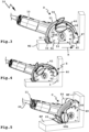
- a hand-held cutting device 10 has a machine housing 11 in which a drive motor 12, for example an electric drive motor, is accommodated.
- the machine housing 11 has a handle section 13 that can be grasped by an operator.
- a switch 17 for switching the drive motor 12 on and/or off is provided, for example.
- a handle 15 protrudes laterally from the machine housing 11, for example its head 14. An operator can therefore grasp the separating device 10 with two hands on the one hand by the handle section 13 and on the other hand by the handle 15 projecting to the side and guide it safely.
- the drive motor 12 drives a tool holder 18, directly or via a gear 16, for example a so-called angular gear, to which a cutting tool 19 can be releasably attached.
- a power cable 20 is arranged on the handle section 13, so that the hand-held disconnecting device 10 can be operated, for example, via an electrical supply network, for example with 120-230 V alternating voltage.
- a battery-powered hand-held disconnecting device would also be easily possible, ie a hand-held disconnecting device that has an energy storage device on board.
- the machine housing 11 has a guide body 21 close to the tool holder 18, for example a guide plate 22, with which the hand-held cutting device 10 can be guided along a surface, for example a work object W1, for example a stone, a tile or the like.
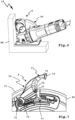
- the cutting tool 19 brings one in, for example Figure 2 indicated separating cut in the work object W1.
- the guide body 21 extends below the head 14 and has a guide surface 23 which is at an angle 24 to a longitudinal axis 25 of the handle section 13.
- the guide table or guide body 21 is arranged, for example, directly on the machine housing 11, whereby it is expedient to make the angle 24 adjustable so that the operator can set an ergonomically favorable angular position of the handle section 13 relative to the guide surface 23.
- a configuration is advantageous in that the guide body 21 forms part of a covering device 30, which is firmly attached to the machine housing 11 or can be detachably attached to the machine housing 11, for example can be mounted in the area of the tool holder 18.
- the covering device 30 has a side edge cover 31 which is fixed in place with respect to the machine housing 11 and which extends over an outer circumference 26 of the cutting tool 19 and covers a predetermined angular range of the cutting tool 19.
- the fixed side edge cover 31 is located next to the handle section 13. The fixed side edge cover 31 therefore supports the operator from injuries caused by the cutting tool 19.
- the side edge cover 31 covers a side edge 28 of the cutting tool 19.
- the fixed side edge cover 31 essentially only extends over the outer circumference 26 of the cutting tool 19, while a side surface 27 of the cutting tool facing away from the machine housing 11 is essentially free.
- the risk of injury is significantly lower there because the operator usually grasps the handle section 13 and the handle 15 and is therefore not in danger of reaching into the cutting elements, blades or the like located on the outer circumference 26.
- the guide plate 22 extends below the head 14 and backwards to the handle 15 (rear in relation to the working direction A).
- the guide plate 22 further extends under a rear end section 32 of the side edge cover 31, so that it is supported in the working direction A at the rear of the work object W1.
- the rear area of the machine housing 11, namely the handle section 13 is guided and supported in this way on the work object W1.
- the side edge cover 31 also has a side wall 33 projecting from a top wall 35, which covers a side surface of the cutting tool 19 that is opposite to the side surface 27, and therefore covers it relative to the machine housing 11 and thus the handle section 13. The risk of injury is therefore very low.
- the side edge cover 31 is approximately U-shaped, i.e. has a short cover leg 34 extending towards the side surface 27.
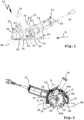
- the covering device 30 further has a movable covering element 40, which in the present case can be pivoted relative to the stationary part of the covering device 30, namely the side edge cover 31, namely about the tool axis 29, which at the same time defines the pivot axis S of the covering element 40.
- the cover element 40 protects in one Figures 1-3 Covering position D shown is next to the circumferential region of the cutting tool 19 covered by the side edge cover 31, namely a section 26a, of the outer circumference 26.
- the cover element 40 can be pivoted about the pivot axis S in the direction of the stationary part of the cover device 30, namely the side edge cover 31, which in Figure 4 partially and in Figure 5 has completely happened.
- the cover element 40 then assumes an open position O, in which a larger area of the outer circumference 26 of the cutting tool 19 is released, for example an angular range of approximately 190°.
- the covering element 40 prefferably brought manually from the covering position D into an intermediate position Z, for example corresponding to the position in Figure 4 , before it can be further, in particular completely, adjusted in the direction of the open position O by resting on a top side of the work object and / or, for example, in the working direction A, frontally located contact surface or wall surface WF. No operator intervention is necessary for this movement section.
- the wall surface WF is part of the work object W1. However, it could also be a contact surface or stop surface that is separate from the work object.
- the open position O In the open position O, the peripheral area 26b and also the section 26a are released.
- the open position O is, so to speak, the maximum open position, the covering position D, so to speak maximum closed position and accordingly numerous intermediate positions between these two maximum positions, for example intermediate positions determined by a latching, or particularly preferably infinitely adjustable intermediate positions are possible. This can be seen particularly in connection with the Figures 3-5 , where the cover element 40 continuously pivots between the cover position D and the open position O.
- the cover element 40 has a cover body 41 which is approximately U-shaped in cross section.
- a cover wall 42 is therefore provided, which is located on the radial outer circumference 26 of the cutting tool 19 and from which the side legs 43, 44 protrude.
- the side leg 44 serves to cover the free side surface 27 of the cutting tool 19, the other side leg 43 forms a cover wall and extends next to the side wall 33 of the stationary side edge cover 31 and covers the side surface of the cutting tool 19 opposite the side surface 27.
- a stop body 46 is provided at a front, free end region 45 of the cover element 40.
- the stop body 46 has, for example, a stop projection 47, which when striking an inner corner I of a work object W2, shown for example in the Figures 3-5 , the cover element 40 is actuated from the cover position D in the direction of the open position O, see Figure 4 .
- the stop projection 47 on which a sliding surface, roller, roller or the like can be arranged, slides, for example, on a stop surface or contact surface, in particular a wall surface WF of the work object W2, whereby the cover element 40 is driven to pivot about the pivot axis S.
- the penetration depth of the cutting tool 19 is, for example, in the area of one leg of the work object W2, for example the bottom surface BF, about 20-25% of the diameter of the cutting tool 19, specifically for example about 21-23% or 22%.
- the cutting tool 19 penetrates the wall surface WF somewhat less deeply, but still at least about 10-20%, in the present case about 13-17%, in particular about 15% of the diameter of the cutting tool 19.
- the cover element 40 is pivoted or actuated by a spring arrangement 50 with a spring 51.
- the spring 51 is guided by a guide body 52, for example around a mandrel, which extends in an arc below the stationary side edge cover 31 and thus essentially forces the spring 51 into a circular path.
- the guide body 52 has a curved course and extends between the end region of the side edge cover 31 located next to the guide plate 22 and an end region 48 of the cover element 40 opposite the end region 45.
- the spring 51 on the other hand, can extend beyond the end region 48 into a receiving channel 49 of the Cover element 40 extend in when the cover element 40 is in the covering position D ( Figure 8 ). In any case, the spring 51 is supported on the other end region 45 of the cover element 40. So when the cover element 40 is moved from the cover position D towards the open position O, the spring 51 in the interior of the receiving channel 49 is compressed and tensioned.
- the tool holder 18 and thus the cutting tool 19 has a direction of rotation 53 such that it rotates out of the stationary side edge cover 31 in the direction of the movable cover element 40. It is expediently provided that when separating the work object W1 or W2, particles formed in an exit region 59 of the separating tool 19 are, so to speak, thrown out of the work object W1 or W2 in the direction of the end region 45 of the movable cover element 40.
- a suction connection 55 is also provided at the end region 45, to which a vacuum cleaner device, for example a suction hose of a vacuum cleaner, can be connected.
- the suction connection 55 comprises a tubular body 56 which is open with an opening 58 into the interior of the cover element 40, i.e. towards the cutting tool 19.
- An angled tubular body 57 is arranged on the tubular body 56, preferably rotatable, so that a suction hose optionally connected to the suction connection 55 has a certain mobility.
- the opening 58 is arranged at the front at the end region 45, so that in the exit region 59 of the cutting tool 19 dust emerging from the work object W1 or W2 can be sucked directly into the opening 58, thus, for example, a scribe line M is kept free and visible.
- the side edge cover 31 and the cover element 40 leave a relatively large assembly opening 36 through which the cutting tool 19 can be mounted on the tool holder 18 or removed from the tool holder 18.
- the cover leg 34 like the side leg 44, is relatively short towards the tool holder 18 or in the radial direction towards the tool axis 29. The operator may only have to lower the cutting tool 19 slightly Push a downwardly projecting area 44b of the side leg 44 in order to then be able to conveniently attach it to the tool axis or the tool holder 18.
- the protruding area 44b enables, for example, better protection for the operator if he grips the handle 15 and possibly slips slightly, i.e. could reach the cutting tool 19.
- the movable cover element 40 pivots in the direction of the open position O towards the fixed section, namely the side edge cover 31, and thereby passes under the top wall 35.
- the movable cover element 40 therefore pivots under the side edge cover 31.
- the side leg 43 which is designed like a wall, is rotatably mounted on a pivot bearing surface 60, for example.
- arms 61 which protrude from the side leg 43 radially inwards or in the direction of the tool holder 18, are supported on the front side or with their free end regions on the pivot bearing surface 60.
- the pivot bearing surface 60 is, for example, a cylindrical outer circumference of a pivot bearing body 65.
- rollers or sliding surfaces are provided on the free end regions.
- the arms 61 to encompass, for example, an annular body 62 of the stationary section of the covering device 30, for example the side edge cover 31, or to be rotatably mounted on it.
- the annular body 62 is part of the side wall 33 or connected to it.
- the stationary part of the cover device 30, for example the side wall 33, is preferably screwed to the machine housing 11, for example with screws 63, and / or is clamped to a flange 64 which surrounds the tool holder 18 or screwed to it or in some other way connected to this.
- the covering device 30 is designed to be detachable from the machine housing 11, so that it can be removed or replaced with another covering device if necessary.
- a fixing device 70 is provided, which is in a fixing position F, for example accordingly Figure 3 or 2 , which holds the cover element 40 stationary with respect to the fixed part of the cover device 30, namely the side edge cover 31.
- the fixing device 70 comprises a pawl 71, which is pivotally mounted on the cover element 40 on a pivot bearing 72.
- the pivot bearing 72 includes, for example, a bolt 73 which extends between the side legs 43, 44.
- the pawl 71 has a pawl projection 74, which can hook on a front, free end region 37 of the side edge cover 31 when it is in the fixing position F ( Figure 7 ) takes.
- the pawl 71 further comprises a section 75 which can be gripped, for example, with a thumb or another finger and which serves as a hand actuation element 76.
- the pawl 71 is preferably biased by a spring 77 in the direction of the fixing position F, ie the pawl projection 74 hooks into the front free end region 37.
- the pawl 71 must be pivoted away from the side edge cover 31 in order to bring the pawl projection 74 out of engagement with the end regions 37 of the side edge cover 31. So if the operator presses on the pawl 71 in the direction of the cutting tool 19, this does not lead to the fixing device 70 being released, but rather acts in the opposite sense, namely in the direction of the fixing position F.
- the guide plate 22 extends only essentially below or next to the side edge cover 31, but not in the area of the cover element 40, so that when the cover element 40 is pivoted into the open position O, the section 26a of the cutting tool 19 is freely in the ground, for example Wall surface WF, can cut into.
- a guide surface 45b arranged on its underside, which extends coplanar to the guide surface 23 also guides and supports the hand-held separating device 10 in the working direction A at the front ( Figure 8 ).
Description
Die Erfindung betrifft ein freihändig führbares Hand-Trenngerät, insbesondere Handtrennschleifer oder Winkelschleifer, gemäß dem Oberbegriff des Anspruchs 1.The invention relates to a hand-held cutting device that can be operated hands-free, in particular a hand-held cut-off grinder or angle grinder, according to the preamble of claim 1.
Es ist allgemein bekannt, bei sogenannten Winkelschleifern die Oberseite der Trennscheibe, also des Trennwerkzeugs, durch eine Haube abzudecken. Diese Maßnahme trägt zur Sicherheit bei und ermöglicht zudem eine Staubabfuhr, indem z.B. an einer derartigen Abdeckvorrichtung, beispielsweise einer Abdeckhaube, ein Sauganschluss zum Absaugen von Partikeln, Spänen oder dergleichen, die beim Betrieb des Trenngeräts anfallen, angeordnet ist.It is generally known to cover the top of the cutting disc, i.e. the cutting tool, with a hood in so-called angle grinders. This measure contributes to safety and also enables dust removal, for example by arranging a suction connection on such a covering device, for example a cover hood, for suctioning off particles, chips or the like that arise during operation of the separating device.
Die bekannten Abdeckvorrichtungen müssen jedoch, wenn sie beim Arbeitsbetrieb im Weg sind, abgebaut werden. Beispielsweise ist dann eine Verklemmung mit einem Flansch, an dem die Werkzeugaufnahme vorgesehen ist, zu lösen. Das ist allerdings umständlich.However, the known covering devices must be dismantled if they get in the way during work. For example, a jam with a flange on which the tool holder is provided must then be solved. However, this is complicated.
Ein Hand-Trenngerät gemäß dem Oberbegriff des Anspruchs 1 ist z.B. in
Es ist daher die Aufgabe der vorliegenden Erfindung, eine verbesserte Abdeckvorrichtung, insbesondere eine Absaughaube, für Trenngeräte, beispielsweise sogenannte Winkelschleifer, bereitzustellen.It is therefore the object of the present invention to provide an improved covering device, in particular a suction hood, for cutting devices, for example so-called angle grinders.
Zur Lösung der Aufgabe ist ein Hand-Trenngerät gemäß der technischen Lehre des Anspruchs 1 vorgesehen.To solve the problem, a hand-held cutting device is provided according to the technical teaching of claim 1.
Bei dessen Formulierung wird z.B. zwischen einer maximal geöffneten Offenstellung und der Abdeckstellung unterschieden. Man könnte aber auch sagen, dass das Abdeckelement zwischen der Abdeckstellung und einer maximalen Offenstellung verstellbar ist und mindestens eine Offenstellungsposition als Zwischenposition zwischen der Abdeckstellung und der maximalen Offenstellung vorgesehen ist.When formulating it, a distinction is made, for example, between a maximum open position and the covering position. But one could also say that the cover element is adjustable between the cover position and a maximum open position and at least one open position is provided as an intermediate position between the cover position and the maximum open position.
Es ist ein Grundgedanke der vorliegenden Erfindung, dass die Abdeckvorrichtung, die beispielsweise in der Art einer Haube ausgestaltet ist, mehrteilig ist, wovon jedoch nur ein Teil bezüglich des Maschinengehäuses ortsfest ist, nämlich die Seitenrandabdeckung. Diese kann selbstverständlich auch einen großen Teil des Trennwerkzeugs bzw. der Trennscheibe einhausen, beispielsweise auch eine Stirnseite oder Flachseite. Das Abdeckelement hingegen ist beweglich, das heißt es kann um die Werkzeug- oder Drehachse des Trennwerkzeugs oder eine dazu parallele Achse schwenken und so einen größeren Arbeitsbereich des Trennwerkzeugs freigeben, was beispielsweise für Trennschnitte in Innen-Eckbereiche des Werkobjekts vorteilhaft ist.It is a basic idea of the present invention that the covering device, which is designed, for example, in the manner of a hood, is made up of several parts, of which, however, only one part is stationary with respect to the machine housing, namely the side edge cover. This can of course also house a large part of the cutting tool or the cutting disk, for example also a front side or flat side. The cover element, on the other hand, is movable, that is, it can pivot about the tool or rotation axis of the cutting tool or an axis parallel to it and thus release a larger working area of the cutting tool, which is advantageous, for example, for separating cuts in inner corner areas of the work object.
Vorteilhaft ist vorgesehen, dass an dem Abdeckelement ein Sauganschluss für eine Staubabsaugeinrichtung angeordnet ist.It is advantageously provided that a suction connection for a dust extraction device is arranged on the cover element.
Der Sauganschluss an dem beweglichen Abdeckelement ist sozusagen stets an Ort und Stelle, nämlich dort wo der Staub entsteht. Der Staub wird also vorteilhaft direkt an seinem Entstehungsort abgesaugt.The suction connection on the movable cover element is, so to speak, always in place, namely where the dust arises. The dust is therefore advantageously extracted directly at its source.
Eine Drehrichtung des Trennwerkzeugs ist vorzugsweise so, dass es aus dem Werkstück austretend in Richtung des Sauganschlusses dreht. Der sozusagen aus dem Werkstück herausgeschleuderte Staub kann also vorteilhaft unmittelbar abgesaugt werden, nämlich durch den Sauganschluss.A direction of rotation of the cutting tool is preferably such that it emerges from the workpiece and rotates in the direction of the suction connection. The dust thrown out of the workpiece, so to speak, can advantageously be sucked off directly, namely through the suction connection.
Es ist also eine Staubabsaugung möglich. An dem beweglichen Abdeckelement, ist ein Sauganschluss für eine Staubabsaugeinrichtung, beispielsweise einen Staubsauger, angeordnet. Bei dem Sauganschluss handelt es sich vorzugsweise um einen Stutzen oder Rohrkörper, an den ein Saugschlauch anschließbar ist. Somit können am Arbeitsort anfallende Artikel, Späne oder dergleichen, direkt durch die Abdeckvorrichtung hindurch abgesaugt werden.Dust extraction is therefore possible. A suction connection for a dust extraction device, for example a vacuum cleaner, is arranged on the movable cover element. The suction connection is preferably a nozzle or pipe body to which a suction hose can be connected. This means that items, chips or the like that arise at the work site can be sucked out directly through the covering device.
Besonders bevorzugt ist es, wenn der Anschluss an den freien Endbereich des Abdeckelements angeordnet ist. Bevorzugt ist dies dann der vordere oder vorderste Arbeitsbereich des Trennwerkzeugs, d.h. dass direkt am Austrittsbereich des Trennwerkzeugs aus dem Werkobjekt die Späne, Partikel oder dergleichen anderer Schmutz direkt abgesaugt werden.It is particularly preferred if the connection is arranged on the free end region of the cover element. This is then preferably the front or foremost working area of the cutting tool, i.e. the chips, particles or similar other dirt are sucked out of the work object directly at the exit area of the cutting tool.
Zweckmäßigerweise ist vorgesehen, dass zwischen dem Trennwerkzeug und dem beweglichen Abdeckelement ein Freiraum oder Sichtbereich frei bleibt, so dass eine sich in Arbeitsrichtung frontal vor dem Trennwerkzeug erstreckende Anrisslinie sichtbar ist. Beispielsweise ist ein Sichtfenster oder Sichtbereich seitlich zwischen dem Trennwerkzeug und dem Abdeckelement vorgesehen.It is expediently provided that a free space or viewing area remains free between the cutting tool and the movable cover element, so that a scribe line extending frontally in front of the cutting tool in the working direction is visible. For example, a viewing window or viewing area is provided laterally between the cutting tool and the cover element.
Bei dem Handtrenngerät handelt es sich vorzugsweise um einen Trennschleifer, insbesondere einen Winkelschleifer.The hand-held cutting device is preferably a cut-off grinder, in particular an angle grinder.
Die Abdeckvorrichtung, insbesondere das bewegliche Abdeckelement, befindet sich beim Betrieb des Handtrenngerätes vorteilhaft auf der Oberseite des Werkstücks oder an der Oberseite des Werkstücks.The covering device, in particular the movable covering element, is advantageously located on the top of the workpiece or on the top of the workpiece when the hand-held cutting device is in operation.
Die Abdeckvorrichtung kann auch ein von dem Trenngerät separates oder separierbares Bauteil sein, die man auch so definieren kann:
Abdeckvorrichtung für ein freihändig führbares Hand-Trenngerät, das eine Werkzeugaufnahme für ein scheibenförmiges Trennwerkzeug zum Einbringen eines Trennschnittes in ein zu bearbeitendes Werkobjekt und einen in einem Maschinengehäuse angeordneten Antriebsmotor zum Dreh-Antreiben der Werkzeugaufnahme um eine Werkzeugachse aufweist, wobei die Abdeckvorrichtung zum Abdecken des Trennwerkzeugs vorgesehen ist und an dem Maschinengehäuse, insbesondere einem Flanschabschnitt der Werkzeugaufnahme, lösbar montierbar ist und eine beim Betrieb des Trenngeräts am Maschinengehäuse ortsfest festgelegte Seitenrandabdeckung zum Abdecken eines Seitenrands des Trennwerkzeugs umfasst, dadurch gekennzeichnet, dass sie ein relativ zu der Seitenrandabdeckung um eine mit der Werkzeugachse koaxiale oder zu der Werkzeugachse parallele Schwenkachse zwischen einer Abdeckstellung und mindestens einer Offenstellung schwenkbares Abdeckelement zum Abdecken eines vor die ortsfeste Seitenrandabdeckung vorstehenden Arbeitsabschnitts des Seitenrands des Trennwerkzeugs aufweist, wobei das Abdeckelement in der Abdeckstellung einen größeren Teil des Arbeitsabschnitts des Trennwerkzeugs als in der Offenstellung abdeckt und dass an dem Abdeckelement ein Sauganschluss für eine Staubabsaugeinrichtung angeordnet ist.The covering device can also be a separate or separable component from the separating device, which can also be defined as follows:
Covering device for a hands-free hand-held cutting device, which has a tool holder for a disk-shaped cutting tool for making a separating cut in a work object to be machined and a drive motor arranged in a machine housing for rotating the tool holder about a tool axis, the covering device for covering the cutting tool is provided and can be releasably mounted on the machine housing, in particular a flange section of the tool holder, and comprises a side edge cover which is fixed in place on the machine housing during operation of the separating device for covering a side edge of the separating tool, characterized in that it has a side edge cover relative to the side edge cover about one with the tool axis coaxial or to the tool axis parallel pivot axis between a covering position and at least one open position pivotable cover element for covering a working section of the side edge of the cutting tool protruding in front of the stationary side edge cover, the cover element in the covering position covering a larger part of the working section of the cutting tool than in the open position and that on the cover element Suction connection for a dust extraction device is arranged.
Erfindungsgemäß ist vorgesehen, dass das Abdeckelement an einem von der ortsfesten Seitenrandabdeckung am weitesten entfernten freien Endbereich durch Anlage an einer Anlagefläche in Arbeitsrichtung frontal vor dem Abdeckelement, in Richtung der Offenstellung betätigbar ist.According to the invention, it is provided that the cover element can be actuated in the direction of the open position at a free end region that is furthest away from the stationary side edge cover by resting on a contact surface in the working direction, frontally in front of the cover element.
Vorteilhaft ist bei der Abdeckvorrichtung vorgesehen, dass das Abdeckelement an einem von der ortsfesten Seitenrandabdeckung am weitesten entfernten freien Endbereich durch Anlage an dem Werkobjekt, insbesondere an dessen Oberseite, in Richtung der Offenstellung betätigbar ist.It is advantageously provided in the covering device that the covering element can be actuated in the direction of the open position at a free end region that is furthest away from the stationary side edge cover by resting on the work object, in particular on its top side.
Die ortsfeste Seitenrandabdeckung könnte auch ein Bestandteil des Maschinengehäuses sein.The stationary side edge cover could also be part of the machine housing.
Die Anlagefläche steht beispielsweise vor die Oberseite des Werkobjekts vor. Die Anlagefläche kann ein Bestandteil des Werkobjekts sein.The contact surface projects, for example, in front of the top of the work object. The contact surface can be part of the work object.
Es ist möglich, dass das Abdeckelement zunächst manuell über einen Teilabschnitt aus der Abdeckstellung in Richtung der Offenstellung in eine Zwischenstellung zu betätigen ist und anschließend durch Anlage an dem Werkobjekt oder an der frontal in Arbeitsrichtung befindlichen Anlagefläche aus der Zwischenstellung weiter in Richtung der Offenstellung betätigbar ist. In der Zwischenstellung ist eine Anschlagfläche des Abdeckelements zum Anschlagen an dem Werkobjekt oder der Anlagefläche zweckmäßigerweise bereits außerhalb eines Abstands zwischen seiner Schwenkachse und dem Werkobjekt.It is possible for the cover element to first be actuated manually over a section from the covering position in the direction of the open position to an intermediate position and then to be actuated from the intermediate position further in the direction of the open position by resting on the work object or on the contact surface located frontally in the working direction . In the intermediate position, a stop surface of the cover element for striking against the work object or the contact surface is expediently already outside a distance between its pivot axis and the work object.
Das Abdeckelement schlägt zweckmäßigerweise an der Oberseite des Werkstücks an bzw. ist durch Anlage an der Oberseite des Werkstücks in Richtung der Offenstellung betätigbar.The cover element expediently abuts on the top of the workpiece or can be actuated in the direction of the open position by resting on the top of the workpiece.
Es ist erfindungsgemäß vorgesehen, dass das Abdeckelement an einer Anschlagfläche anschlägt, die sich bezogen auf die Arbeitsrichtung frontal vor dem Abdeckelement erstreckt. Gemäß einer Definition des Anspruchs 1 steht diese Anlagefläche nach oben vor die Oberseite oder Oberfläche des Werkstücks, insbesondere rechtwinkelig oder winkelig, vor. Man kann die Anlagefläche auch als Anschlagfläche bezeichnen.According to the invention, it is provided that the cover element abuts on a stop surface which extends frontally in front of the cover element in relation to the working direction. According to a definition of claim 1, this contact surface projects upwards in front of the top or surface of the workpiece, in particular at right angles or at an angle. The contact surface can also be referred to as the stop surface.
Bevorzugt ist vorgesehen, dass das Abdeckelement durch eine Anlage oder durch Anschlagen an einem insbesondere rechtwinkeligen Innen-Eckbereich des Werkobjekts öffenbar ist.It is preferably provided that the cover element can be opened by abutment or by striking a particularly rectangular inner corner region of the work object.
Es ist möglich, dass an der ortsfesten Seitenrandabdeckung und/oder an dem beweglichen Abdeckelement, zweckmäßigerweise ein Sauganschluss für eine Staubabsaugeinrichtung, beispielsweise einen Staubsauger, angeordnet ist.It is possible for a suction connection for a dust extraction device, for example a vacuum cleaner, to be expediently arranged on the stationary side edge cover and/or on the movable cover element.
Der Antriebsmotor ist zweckmäßigerweise ein elektrischer Antriebsmotor. Das Trenngerät ist als Hand-Werkzeugmaschine ausgestaltet. Das Trenngerät kann netzgebunden betreibbar sein, d.h. dass es beispielsweise ein Anschlusskabel zum Anschluss an ein elektrisches Versorgungsnetz aufweist. Bevorzugt ist auch eine Variante mit Akkubetrieb oder Batteriebetrieb, d.h. dass das Trenngerät beispielsweise eine Akku-Schnittstelle zum Anschluss eines Akkupacks oder einer Batterie aufweist.The drive motor is expediently an electric drive motor. The cutting device is designed as a hand-held machine tool. The separating device can be operated in a network-connected manner, i.e. it has, for example, a connecting cable for connection to an electrical supply network. A variant with battery operation or battery operation is also preferred, i.e. that the separating device has, for example, a battery interface for connecting a battery pack or a battery.
Es ist zum Beispiel möglich, dass die ortsfeste Seitenrandabdeckung etwa die Hälfte des von der Abdeckvorrichtung abgedeckten Bereich des Trenngeräts abdeckt, das bewegliche Abdeckelement die andere Hälfte des in der Abdeckstellung abgedeckt Bereichs des Trennwerkzeugs abdeckt. Selbstverständlich könnte das Abdeckelement auch größer sein, d.h. dass es einen größeren Winkelbereich des Trennwerkzeugs in der Abdeckstellung überdeckt als die ortsfeste Seitenrandabdeckung oder umgekehrt ein kleineres Abdeckelement vorgesehen sein, das nur einen kleineren Umfangsbereich des Trennwerkzeugs abdeckt als die ortsfeste Seitenrandabdeckung.It is possible, for example, for the stationary side edge cover to cover approximately half of the area of the separating device covered by the covering device, and for the movable covering element to cover the other half of the area of the separating tool covered in the covering position. Of course, the cover element could also be larger, i.e. that it covers a larger angular range of the cutting tool in the covering position than the stationary side edge cover or, conversely, a smaller cover element could be provided which only covers a smaller peripheral area of the cutting tool than the stationary side edge cover.
Eine bevorzugte Ausführungsform der Erfindung, die gerade für Schnitte in Innen-Eckbereiche vorteilhaft ist, sieht vor, dass die Abdeckvorrichtung in der Offenstellung des Abdeckelements einen Winkelbereich von etwa oder mindestens 160° freigibt. Besonders bevorzugt ist es, wenn ein noch größerer Winkelbereich frei steht, beispielsweise ein Winkelbereich von etwa 160-180°. Besonders bevorzugt ist ein Winkelbereich von etwa 190°. Der Winkelbereich ist bezogen auf die Drehachse der Werkzeugaufnahme oder des Trennwerkzeugs.A preferred embodiment of the invention, which is particularly advantageous for cuts in inner corner areas, provides that the covering device releases an angular range of approximately or at least 160° in the open position of the covering element. It is particularly preferred if an even larger angular range is free, for example an angular range of approximately 160-180°. An angular range of approximately 190° is particularly preferred. The angular range is related to the axis of rotation of the tool holder or the cutting tool.
Jedenfalls sieht eine Definition des Anspruchs 1 vor, dass bei geöffneten Abdeckelement bzw. vollständig in die Offenstellung geschwenktem Abdeckelement ein größerer Winkelbereich des Außenumfangs des Trennwerkzeugs zum Eindringen in das Werkobjekt bereitsteht als mindestens 180°.In any case, a definition of claim 1 provides that when the cover element is open or the cover element is pivoted completely into the open position, a larger angular range of the outer circumference of the cutting tool is available for penetration into the work object than at least 180 °.
Es ist weiterhin zweckmäßig, wenn in der Offenstellung oder Offenstellung des Abdeckelements, jedenfalls in der vollständig geöffneten Stellung, in welcher der größte Umfangsbereich des Trennwerkzeugs frei steht, das Trennwerkzeug in einen etwa rechtwinkeligen Innen-Eckbereich des Werkobjekts an beiden Seiten zu mindestens 10%, vorzugsweise 20% oder 30% des Durchmessers des Trennwerkzeugs eindringen kann. Die Eindringtiefe kann aber z.B. an einer Unterseite größer sein, z.B. 20-25 %, insbesondere etwa 22 %, während die frontale Eindringtiefe kleiner ist, z.B. 10-20 %, insbesondere etwa 15 %.It is also useful if in the open position or open position of the cover element, at least in the fully open position in which the largest circumferential area of the cutting tool is free, the cutting tool is at least 10% into an approximately rectangular inner corner area of the work object on both sides. preferably 20% or 30% of the diameter of the cutting tool can penetrate. However, the penetration depth can, for example, be greater on an underside, for example 20-25%, in particular about 22%, while the frontal penetration depth is smaller, for example 10-20%, in particular about 15%.
Weiterhin ist es zweckmäßig, wenn in der Abdeckstellung des Abdeckelements zumindest ein Teilbereich des Trennwerkzeugs frei ist, beispielsweise ein Winkelbereich von etwa 45°bis 130°, beispielsweise 90 bis 120 Grad, insbesondere von etwa 110°.Furthermore, it is expedient if at least a portion of the cutting tool is free in the covering position of the covering element, for example an angular range of approximately 45° to 130°, for example 90 up to 120 degrees, especially around 110°.
Vorzugsweise ist vorgesehen, dass die Drehrichtung des Trennwerkzeugs derart ausgestaltet ist, dass es das Trennwerkzeug von dem Abdeckelement her zu der ortsfesten Seitenrandabdeckung hin antreibt. Beispielsweise tritt das Trennwerkzeug aus dem Werkobjekt vorne, am freien Endbereich des Abdeckelements aus, wo dann auch gleich die Staubabsaugung stattfindet, d.h. der Sauganschluss angeordnet ist. Der Vorteil ist dabei, dass das Abdeckelement sozusagen mit dem Austrittsbereich aus des Trennwerkzeugs aus dem Werkobjekt mit wandert und zugleich auch der Sauganschluss immer am optimalen Ort, nämlich an dem sozusagen wandernden Austrittsbereich des Trennwerkzeugs vorgesehen ist. Gerade im Zusammenhang mit dem bereits erwähnten Trennschnitt in Innen-Eckbereichen des Werkobjekts ist diese Maßnahme besonders vorteilhaft.It is preferably provided that the direction of rotation of the cutting tool is designed such that it drives the cutting tool from the cover element towards the stationary side edge cover. For example, the cutting tool emerges from the work object at the front, at the free end region of the cover element, where dust extraction then takes place, i.e. the suction connection is arranged. The advantage here is that the cover element, so to speak, moves with the exit area from the cutting tool out of the work object and at the same time the suction connection is always provided at the optimal location, namely at the so-called moving exit area of the cutting tool. This measure is particularly advantageous in connection with the already mentioned separating cut in the inner corner areas of the work object.
Das Abdeckelement weist beispielsweise an dem freien Endbereich, der am Werkobjekt anschlägt, eine Rolle, eine Gleitfläche, einen Gleitkörper oder dergleichen auf. Zweckmäßig ist auch ein vor das Abdeckelement vorstehender Anschlagvorsprung zum Anschlagen oder zur Anlage an dem Werkobjekt angeordnet. Jedenfalls versorgt dieser freie Endbereich bzw. die daran angeordneten Betätigungskörper (Rolle, Gleitfläche oder dergleichen) dafür, dass das Abdeckelement günstig in Richtung der Offenstellung verstellbar ist. Der Anschlagvorsprung kann auch in der Art eines Auslegers ausgestaltet sein.The cover element has, for example, a roller, a sliding surface, a sliding body or the like on the free end region that abuts the work object. A stop projection projecting in front of the cover element for striking or resting on the work object is also expediently arranged. In any case, this free end region or the actuating bodies arranged thereon (roller, sliding surface or the like) ensure that the cover element can be conveniently adjusted in the direction of the open position. The stop projection can also be designed in the manner of a cantilever.
Eine Anschlagfläche am freien Endbereich des Abdeckelements oder des Anschlagvorsprungs, die vorteilhaft eine Gleitfläche, eine Rolle oder dergleichen andere Gleitelemente oder bewegliche Elemente umfasst oder als Gleitfläche, Rolle oder bewegliches Element ausgestaltet ist, ist zweckmäßigerweise außerhalb eines Abstands zwischen einerseits der Schwenkachse des Abdeckelements und andererseits dem Werkobjekt oder einer zur Führung an dem Werkobjekt vorgesehenen Führungsfläche, beispielsweise einem Führungstisch, der Hand-Werkzeugmaschine oder der Abdeckvorrichtung angeordnet, sodass das Abdeckelement selbsttätig durch Anschlagen an dem Werkobjekt oder der frontal in Arbeitsrichtung vorn liegenden Anlagefläche in Richtung der Offenstellung betätigbar ist. Die Anschlagfläche kann ein Drehmoment auf das Abdeckelement in Richtung der Offenstellung ausüben.A stop surface on the free end region of the cover element or the stop projection, which advantageously comprises a sliding surface, a roller or similar other sliding elements or movable elements or is designed as a sliding surface, roller or movable element, is expediently outside a distance between on the one hand the pivot axis of the cover element and on the other hand the work object or a guide surface provided for guidance on the work object, for example a guide table, the hand-held machine tool or the covering device, so that the cover element can be actuated automatically in the direction of the open position by striking the work object or the contact surface located frontally in the working direction. The stop surface can exert a torque on the cover element in the direction of the open position.
Bevorzugt ist das Abdeckelement in Richtung der Abdeckstellung angefedert, beispielsweise durch eine Federanordnung. Besonders bevorzugt erstreckt sich die Federanordnung an einem Innenumfang der ortsfesten Seitenrandabdeckung. Es ist aber auch möglich, dass die Federanordnung eine Feder umfasst, die ihnen am Abdeckelement oder außen am Abdeckelement angeordnet ist und sich am Maschinengehäuse oder der ortsfesten Seitenrandabdeckung abstützt.The covering element is preferably spring-loaded in the direction of the covering position, for example by a spring arrangement. The spring arrangement particularly preferably extends on an inner circumference of the stationary side edge cover. However, it is also possible for the spring arrangement to comprise a spring which is arranged on the cover element or on the outside of the cover element and is supported on the machine housing or the stationary side edge cover.
Die Abdeckvorrichtung ist zweckmäßigerweise fixierbar, wofür eine Fixiereinrichtung vorgesehen ist. Die Fixiereinrichtung umfasst beispielsweise eine Rasteinrichtung, d.h. einen Rastvorsprung und eine Rastaufnahme, bevorzugt angefedert. Auch eine Klemmeinrichtung, eine Klinke oder dergleichen sind vorteilhaft anwendbar. Die Fixiereinrichtung dient zum Fixieren des Abdeckelements relativ zu der ortsfesten Seitenrandabdeckung, beispielsweise in der Abdeckstellung oder der Offenstellung oder auch dazwischen liegenden Stellung. Die Fixiereinrichtung ist zwischen einer das Abdeckelement relativ zur ortsfesten Seitenrandabdeckung freigebenden Lösestellung und einer das Abdeckelement gegenüber der Seitenrandabdeckung festlegenden Fixierstellung verstellbar. Beispielsweise ist eine Rastklinke in der entsprechenden Fixierstellung fixierbar. Die Rastklinke oder die sonstige Rasteinrichtung ist zweckmäßigerweise in Richtung der Fixierstellung angefedert, wofür eine Federanordnung vorgesehen ist.The covering device can expediently be fixed, for which a fixing device is provided. The fixing device comprises, for example, a latching device, i.e. a latching projection and a latching receptacle, preferably spring-loaded. A clamping device, a pawl or the like can also be used advantageously. The fixing device serves to fix the cover element relative to the stationary side edge cover, for example in the covering position or the open position or even the position in between. The fixing device is adjustable between a release position that releases the cover element relative to the stationary side edge cover and a fixation position that fixes the cover element relative to the side edge cover. For example, a locking latch can be fixed in the corresponding fixing position. The latching pawl or other latching device is expediently spring-loaded in the direction of the fixing position, for which a spring arrangement is provided.
Die Fixiereinrichtung ist vorzugsweise in Richtung der Fixierstellung angefedert, d.h. dass beispielsweise eine Fixierelement durch eine Federanordnung in Richtung der Fixierstellung belastet ist.The fixing device is preferably spring-loaded in the direction of the fixing position, i.e. that, for example, a fixing element is loaded by a spring arrangement in the direction of the fixing position.
Die Fixiereinrichtung ist zweckmäßigerweise ausschließlich in der Abdeckstellung in die Fixierstellung verstellbar. In der Abdeckstellung ist, wie gesagt, vorzugsweise ein Teilbereich des Trennwerkzeugs für einen Trennschnitt frei, das heißt es kann in das Werkobjekt eingeführt werden und dort Trennschnitte durchführen. Der Vorteil ist dabei, dass der freie Endbereich des Abdeckelements bei fixierter Fixiereinrichtung gleichzeitig eine Führungsfunktion erfüllen kann, d.h. er kann sich an dem Werkobjekt abstützen, um das Trennwerkzeug für einen mit konstanter Tiefe durchgeführten Trennschnitt zu führen.The fixing device is expediently adjustable into the fixing position only in the covering position. In the covering position, as I said, a portion of the cutting tool is preferably free for a cutting cut, that is, it can be inserted into the work object and make cutting cuts there. The advantage is that the free end region of the cover element can simultaneously fulfill a guiding function when the fixing device is fixed, i.e. it can be supported on the work object in order to guide the cutting tool for a cutting cut carried out at a constant depth.
Die Fixiereinrichtung ist zweckmäßigerweise durch einen an einer feststehenden Komponente des Trenngeräts beweglich gelagertes Hand-Betätigungselement betätigbar, welches in einer der Lösestellung zugeordneten Position weiter vor die feststehende Komponente des Trenngeräts vorsteht als in der Fixierstellung. Bei der feststehenden Komponente handelt es sich beispielsweise um einen Bestandteil der Abdeckvorrichtung, besonders bevorzugt um die ortsfeste Seitenrandabdeckung. Der Vorteil dieser Konfiguration ist es, dass eine Entriegelung oder ein Lösen der Fixierung durch einen aktiven Bedienereingriff geschieht, d.h. dass dieser das Hand-Betätigungselement, zum Beispiel einen Betätigungsarm, eine Klinke oder dergleichen, sozusagen von der festen Komponente weg verstellen muss. Wenn beim Arbeitsbetrieb, beispielsweise durch eine unbedachte Bedienhandlung, durch eine Anlage an einem Widerlagerobjekt oder dergleichen, ein Druck auf das Hand-Betätigungselement ausgeübt wird, führt dies nicht zur Entriegelung des Abdeckelements bzw. zum Lösen der Fixiereinrichtung.The fixing device can expediently be actuated by a hand actuating element which is movably mounted on a fixed component of the separating device and which, in a position assigned to the release position, projects further in front of the fixed component of the separating device than in the fixing position. The fixed component is, for example, a component of the covering device, particularly preferably the stationary side edge cover. The advantage of this configuration is that the fixation is unlocked or released through active operator intervention, i.e. the operator has to move the manual actuating element, for example an actuating arm, a latch or the like, away from the fixed component, so to speak. If pressure is exerted on the manual actuation element during work, for example due to a careless operator action, by contacting an abutment object or the like, this does not lead to the unlocking of the cover element or the loosening of the fixing device.
Eine vorteilhafte Maßnahme sieht vor, dass das Abdeckelement ausschließlich über ein Schiebelager an der ortsfesten Seitenrandabdeckung um eine um die Schwenkachse verlaufende gekrümmte Bahn, insbesondere eine Kreisbahn, verschieblich gelagert ist, also ohne ein Drehlager nahe bei der Werkzeugachse, ohne eine Lagerwelle oder einen Lagerbolzen oder dergleichen. Im Bereich der Schwenkachse ist dann keine Schwenklagereinrichtung vorhanden.An advantageous measure provides that the cover element moves exclusively via a sliding bearing on the stationary side edge cover around a curved path running around the pivot axis, in particular a circular path, is displaceably mounted, i.e. without a pivot bearing close to the tool axis, without a bearing shaft or a bearing pin or the like. There is then no pivot bearing device in the area of the pivot axis.
An dieser Stelle sei bemerkt, dass die Schwenkbewegung des Abdeckelements nicht zwingend entlang einer Kreisbahn sein muss, sondern auch entlang einer anderweitig gekrümmten Bahn verlaufen kann.At this point it should be noted that the pivoting movement of the cover element does not necessarily have to be along a circular path, but can also run along a otherwise curved path.
Die Abdeckvorrichtung weist zweckmäßigerweise eine Montageöffnung auf, durch welche die Werkzeugaufnahme für einen Wechsel des Trennwerkzeugs zugänglich ist. Die Montageöffnung kann beispielsweise so bemessen sein, das eine Befestigungsmutter oder dergleichen für das Werkzeug lösbar oder verschließbar ist. Die Montageöffnung kann in der Art eines Fensters ausgestaltet sein.The covering device expediently has a mounting opening through which the tool holder is accessible for changing the cutting tool. The mounting opening can, for example, be dimensioned such that a fastening nut or the like can be detached or closed for the tool. The mounting opening can be designed in the manner of a window.
Besonders bevorzugt ist es, wenn die Montageöffnung großflächig ist, das heißt dass sie einem Durchmesser des Trennwerkzeugs entspricht. Das Trennwerkzeug kann durch die Montageöffnung von dem Trenngerät entfernt werden oder daran montiert werden, ohne dass eine weitere Komponente der Abdeckvorrichtung geöffnet werden muss.It is particularly preferred if the mounting opening has a large area, that is to say that it corresponds to a diameter of the cutting tool. The cutting tool can be removed from the cutting device through the mounting opening or mounted on it without having to open another component of the covering device.
Eine bevorzugte Ausführungsform sieht vor, dass das Abdeckelement oder die ortsfeste Seitenrandabdeckung oder beide ausschließlich den Seitenrand des Trennwerkzeugs abdecken. Besonders bevorzugt wird nur der radial äußere Randbereich des Trennwerkzeugs abgedeckt. Dabei ist es sogar möglich, dass zwischen dem radial äußeren Außenumfang des Trennwerkzeugs und einem nach radial innen vorstehenden Bereich des Abdeckelements oder der Seitenrandabdeckung oder beiden noch ein Abstand vorhanden ist, was eine besonders bequeme Demontage des Trennwerkzeugs von der Werkzeugaufnahme oder Montage oder an die Werkzeugaufnahme ermöglicht.A preferred embodiment provides that the cover element or the stationary side edge cover or both exclusively cover the side edge of the cutting tool. Particularly preferably, only the radially outer edge region of the cutting tool is covered. It is even possible that there is still a distance between the radially outer circumference of the cutting tool and a radially inwardly projecting region of the cover element or the side edge cover or both, which makes dismantling the cutting tool particularly convenient from the tool holder or assembly or to the tool holder enabled.
Eine zweckmäßige Ausführungsform der Erfindung sieht vor, dass das Abdeckelement und/oder die ortsfeste Seitenrandabdeckung ganz oder teilweise aus transparentem Material, zum Beispiel transparenten Kunststoff bestehen. Somit kann der Bediener den Arbeitsbereich des Trennwerkzeugs gut einsehen.An expedient embodiment of the invention provides that the cover element and/or the stationary side edge cover consist entirely or partially of transparent material, for example transparent plastic. This means the operator can clearly see the working area of the cutting tool.
Es ist aber auch möglich, dass das bewegliche Abdeckelement und/oder die ortsfeste Seitenrandabdeckung aus nicht transparenten Material bestehen, zum Beispiel aus Metall oder einem entsprechend eingefärbtem Kunststoff. Es ist weiterhin denkbar, dass nur Teilbereiche aus transparentem, optisch durch lässige Material bestehen, das heißt beispielsweise der vordere, freie Endbereich des Abdeckelements durchsichtig ist, so dass der Bediener beispielsweise einen Austrittsbereich bzw. einen Arbeitsbereich des Trennwerkzeugs, dort wo dieses aus dem Werkobjekt austritt oder in das Werkobjekt eintritt, gut sehen kann.However, it is also possible for the movable cover element and/or the stationary side edge cover to consist of non-transparent material, for example metal or a correspondingly colored plastic. It is also conceivable that only partial areas consist of transparent, optically permeable material, that is, for example, the front, free end area of the cover element is transparent, so that the operator can see, for example, an exit area or a working area of the cutting tool, where it comes out of the work object exits or enters the work object.
Aber auch bei nicht transparentem Material kann das Abdeckelement ohne weiteres so ausgestaltet werden, dass ein Eintrittsbereich oder Austrittsbereich des Trennwerkzeugs gut einsehbar ist. Beispielsweise weist das Abdeckelement einen solchen Abstand zu einer Flachseite des Trennwerkzeugs auf, beispielsweise etwa 1 cm, 2 cm oder 3 cm (Zwischenbereiche sind möglich), dass der Austrittsbereich oder Eintrittsbereich und insbesondere ein in Arbeitsrichtung dem Austrittsbereich oder Eintrittsbereich vorgelagerter Bereich des Werkobjekts für einen Bediener zumindest schräg von der Flachseite des Trennwerkzeugs her einsehbar ist. Somit kann beispielsweise eine Anrisslinie gut gesehen werden.But even with non-transparent material, the cover element can easily be designed so that an entry area or exit area of the cutting tool is clearly visible. For example, the cover element has such a distance from a flat side of the cutting tool, for example approximately 1 cm, 2 cm or 3 cm (intermediate areas are possible), that the exit area or entry area and in particular an area of the work object upstream of the exit area or entry area in the working direction for one The operator can be seen at least obliquely from the flat side of the cutting tool. This means that, for example, a scribe line can be clearly seen.
Vorteilhafte Weiterbildungen der bereits erläuterten Erfindung oder Erfindungen sehen besondere Ausgestaltungen von Führungsflächen vor. Derartige Ausgestaltungen von Führungsflächen können auch an sich eigenständige Erfindungen bilden.Advantageous developments of the invention or inventions already explained provide for special designs of guide surfaces. Such configurations of guide surfaces can also form independent inventions.
Eine Ausführungsform der Erfindung kann vorsehen, dass das Trenngerät keine sich neben der Abdeckvorrichtung am Maschinengehäuse angeordnete Führungsfläche zur Führung an einem Untergrund, beispielsweise einer Führungsschiene, aufweist. Beispielsweise ist keine Führungsplatte vorhanden.One embodiment of the invention can provide that the separating device does not have a guide surface arranged next to the covering device on the machine housing for guiding on a surface, for example a guide rail. For example, there is no guide plate.
Eine Ausführungsform der Erfindung kann auch vorsehen, dass eine relativ schmale oder kleine Führungsplatte vorgesehen ist. Diese kann in einem Ausführungsfall nur an einem von dem Abdeckelement am weitesten entfernten Winkelabschnitt, beispielsweise an einem freien Endbereich, der ortsfesten Seitenrandabdeckung vorgesehen sein.An embodiment of the invention may also provide that a relatively narrow or small guide plate is provided. In one embodiment, this can only be provided on an angle section that is furthest away from the cover element, for example on a free end region, of the stationary side edge cover.
Diese Führungsfläche ist vorzugsweise die einzige Führungsfläche.This guide surface is preferably the only guide surface.
Es ist aber auch möglich, dass sich neben dem Maschinengehäuse eine weitere Führungsfläche oder die entsprechend größere Führungsfläche erstreckt. Bevorzugt bildet die Führungsfläche einen Teil der Abdeckeinrichtung. Beispielsweise ist an der ortsfesten Seitenrandabdeckung der Abdeckvorrichtung eine Führungsplatte vorgesehen.However, it is also possible for a further guide surface or the correspondingly larger guide surface to extend next to the machine housing. The guide surface preferably forms part of the covering device. For example, a guide plate is provided on the stationary side edge cover of the covering device.
Das freie Arbeiten in Innen-Eckbereiche des Werkobjekts hinein wird durch folgende Maßnahme erleichtert. Diese Ausführungsform der Erfindung, die auch eine eigenständige Erfindung im Zusammenhang mit dem Oberbegriff des Anspruchs 1 darstellen kann, sieht zweckmäßigerweise vor, dass am Maschinengehäuse eine oder mehrere ortsfeste Führungsflächen, beispielsweise in der Art einer Führungsplatte oder mehrerer Führungsplatten, vorgesehen sind. Die mindestens eine Führungsfläche, beispielsweise an einer Führungsplatte, kann am Maschinengehäuse selbst vorgesehen sein und/oder zweckmäßigerweise einen Bestandteil der Abdeckvorrichtung bilden. Allerdings erstrecken sich diese Führungsflächen oder die Führungsfläche gemäß einer Definition des Anspruchs 1 in Arbeitsrichtung nach vorn bis maximal zu einem Bereich des Trennwerkzeugs hin, der nicht von dem Abdeckelement freigegeben werden kann. Beispielsweise sind in Arbeitsrichtung nach vorn Führungsflächen nur bis maximal zur Drehachse bzw. Werkzeugaufnahme vorgesehen. Dadurch ist noch immer eine günstige Führung des Trenngeräts am Untergrund möglich. Ein Trennschnitt in eine Innenecke hinein ist jedoch durch die Führungsplatte oder die Führungsflächen nicht behindert.Working freely into the inner corner areas of the work object is made easier by the following measure. This embodiment of the invention, which can also represent an independent invention in connection with the preamble of claim 1, expediently provides that one or more stationary guide surfaces, for example in the manner of a guide plate or several guide plates, are provided on the machine housing. The at least one guide surface, for example on a guide plate, can be provided on the machine housing itself and/or expediently form a component of the covering device. However, according to a definition of claim 1, these guide surfaces or the guide surface extend forward in the working direction up to a maximum of an area of the cutting tool that cannot be released by the cover element. For example, in the forward working direction, guide surfaces are only provided up to a maximum of the axis of rotation or tool holder. This means that the cutting device can still be guided conveniently on the surface. However, a separating cut into an inside corner is not hindered by the guide plate or the guide surfaces.
Im Sinne eines freihändigen Arbeitens und einer bequemen Handhabung der Maschine bzw. des Trenngeräts ist es auch, wenn die Werkzeugaufnahme und die Abdeckeinrichtung an einem freien Endbereich des Maschinengehäuses angeordnet sind.In the interests of hands-free working and convenient handling of the machine or the cutting device, it is also necessary for the tool holder and the covering device to be arranged at a free end region of the machine housing.
Das Maschinengehäuse steht beispielsweise in der Art eines Armes von der Werkzeugaufnahme bzw. dem Trennwerkzeug ab. Bevorzugt ist das Maschinengehäuse in der Art eines mit einer Hand umgreifbaren Handgriffes ausgestaltet. Es ist aber auch möglich, dass das Maschinengehäuse einen solchen Handgriff aufweist, das heißt ein Handgriff am ansonsten nicht direkt umgreifbaren Maschinengehäuse vorgesehen ist.The machine housing, for example, protrudes from the tool holder or the cutting tool in the manner of an arm. The machine housing is preferably designed in the manner of a handle that can be grasped with one hand. However, it is also possible for the machine housing to have such a handle, that is to say a handle is provided on the machine housing that cannot otherwise be gripped directly.
Besonders bevorzugt ist es, wenn das Maschinengehäuse in der Art eines als Handgriff dienenden Haltearms für das Trennwerkzeug ausgestaltet ist. Der Bediener kann also beispielsweise mit einer Hand das Maschinengehäuse umgreifen, wobei dann sozusagen am Kopf oder freien Endbereich des Maschinengehäuses das Trennwerkzeug und die Abdeckvorrichtung vorgesehen sind.It is particularly preferred if the machine housing is designed in the manner of a holding arm serving as a handle for the cutting tool. The operator can, for example, grasp the machine housing with one hand, with the cutting tool and the covering device then being provided, so to speak, on the head or free end region of the machine housing.
Es ist zwar prinzipiell möglich, dass das Trenngerät für eine Art ziehenden Schnitt verwendet wird, d.h. dass ein in Arbeitsrichtung vorderer Endbereich des Trennwerkzeugs in das Werkobjekt einschneidet, sich das Trennwerkzeug oder Schneidplatte sozusagen durch das Werkobjekt hindurch arbeitet und dann hinten, im Bereich der ortsfesten Seitenrandabdeckung aus dem Werkobjekt austritt. In diesem Fall ist es zweckmäßig, wenn hinten am ortsfesten Teil der Abdeckvorrichtung, nämlich im Bereich der ortsfesten Seitenrandabdeckung, der Sauganschluss vorgesehen ist.In principle, it is possible that the cutting device is used for a type of pulling cut, i.e. that a front end region of the cutting tool in the working direction cuts into the work object, the cutting tool or cutting plate, so to speak, works through the work object and then at the back, in the area of the stationary Side edge cover emerges from the work object. In this case, it is expedient if the suction connection is provided at the rear of the stationary part of the covering device, namely in the area of the stationary side edge cover.
Besonders bevorzugt ist jedoch die umgekehrte Arbeitsrichtung, d.h. dass gemäß einer Definition des Anspruchs 1 ein so genannter schiebender Schnitt mit dem Trenngerät in das Werkobjekt vorgenommen wird. Gemäß dieser Definition des Anspruchs 1 ist vorgesehen, dass der Antriebsmotor die Werkzeugaufnahme in einer Drehrichtung antreibt, bei der das Trennwerkzeug vorn im Bereich des Abdeckelements aus dem Werkobjekt austritt und sozusagen unter das Abdeckelement hinein unter die Abdeckvorrichtung hinein dreht. Dort, am Abdeckelement, befindet sich dann zweckmäßigerweise auch der Sauganschluss.However, the reverse working direction is particularly preferred, i.e. that according to a definition of claim 1, a so-called pushing cut is made into the work object with the cutting device. According to this definition of claim 1, it is provided that the drive motor drives the tool holder in a direction of rotation in which the cutting tool emerges from the work object at the front in the area of the cover element and, so to speak, rotates under the cover element under the cover device. The suction connection is then conveniently located there, on the cover element.
Bevorzugt ist der die Werkzeugaufnahme aufweisende Abschnitt des Maschinengehäuses in einer Arbeitsrichtung des Trenngeräts vorn, so dass das Trenngerät für einen schiebenden Trennschnitt ausgestaltet ist. Das Maschinengehäuse steht dabei zweckmäßigerweise nach schräg hinten (in der Arbeitsposition bzw. beim Trenn-Schneiden in das Werkobjekt) von der Werkzeugaufnahme ab.Preferably, the section of the machine housing having the tool holder is at the front in a working direction of the cutting device, so that the cutting device is designed for a pushing cutting cut. The machine housing expediently protrudes diagonally backwards from the tool holder (in the working position or when cutting into the work object).
Nachfolgend wird ein Ausführungsbeispiel der Erfindung anhand der Zeichnung erläutert. Es zeigen:
- Figur 1
- eine perspektivische Schrägansicht eines erfindungsgemäßen Hand-Trenngeräts bei einem Schnitt in eine ebene Oberfläche eines Werkobjekts,
- Figur 2
- das Hand-Trenngerät gemäß
Figur 1 , jedoch von der anderen Seite, - Figur 3
- das Hand-Trenngerät gemäß der vorstehenden Figuren, beim Beginn eines Schnittes in eine Innenecke eines anderen Werkobjekts,
- Figur 4
- das Hand-Trenngerät gemäß
Figur 3 , jedoch bei weiter fortgeschrittenen Schnitt, - Figur 5
- das Hand-Trenngerät gemäß
Figuren 3, 4 bei vollständigem Schnitt in die Innenecke, - Figur 6
- das Hand-Trenngerät gemäß
Figur 5 , jedoch von der anderen Seite her, - Figur 7
- eine Fixiereinrichtung des Hand-Trenngeräts, etwa entsprechend einem Detail X in
Figur 2 , - Figur 8
- das Hand-Trenngerät gemäß der vorstehenden Figuren ohne Trennwerkzeug und mit seinem Abdeckelement in der Abdeckstellung,
- Figur 9
- das Hand-Trenngerät gemäß
Figur 8 , jedoch mit vollständig in die Offenstellung geschwenktem Abdeckelement, und Figur 10- das Hand-Trenngerät von schräg vorn mit teilweise geschnitten dargestelltem Sauganschluss.
- Figure 1
- a perspective oblique view of a hand-held cutting device according to the invention during a cut into a flat surface of a work object,
- Figure 2
- the hand-held cutting device accordingly
Figure 1 , but from the other side, - Figure 3
- the hand cutting device according to the above figures, when starting a cut into an inner corner of another work object,
- Figure 4
- the hand-held cutting device accordingly
Figure 3 , but with more advanced cutting, - Figure 5
- the hand-held cutting device accordingly
Figures 3, 4 with a complete cut into the inner corner, - Figure 6
- the hand-held cutting device accordingly
Figure 5 , but from the other side, - Figure 7
- a fixing device of the hand-held cutting device, approximately corresponding to a detail X in
Figure 2 , - Figure 8
- the hand-held cutting device according to the above figures without a cutting tool and with its covering element in the covering position,
- Figure 9
- the hand-held cutting device accordingly
Figure 8 , but with the cover element pivoted completely into the open position, and - Figure 10
- the hand-held separator from the front at an angle with the suction connection shown partially cut away.
Ein Hand-Trenngerät 10 weist ein Maschinengehäuse 11 auf, in welchem ein Antriebsmotor 12, beispielsweise ein elektrischer Antriebsmotor, aufgenommen ist. Das Maschinengehäuse 11 weist einen Handgriffabschnitt 13 auf, der von einem Bediener umgriffen werden kann. An einer Seite des Maschinengehäuses 11, nahe bei einem Kopf 14, ist beispielsweise ein Schalter 17 zum Einschalten und/oder Ausschalten des Antriebsmotors 12 vorgesehen. Von dem Maschinengehäuse 11, beispielsweise dessen Kopf 14, steht ein Handgriff 15 seitlich ab. Mithin kann also ein Bediener das Trenngerät 10 einerseits am Handgriffabschnitt 13, andererseits am seitlich abstehenden Handgriff 15 mit zwei Händen ergreifen und sicher führen.A hand-held
Der Antriebsmotor 12 treibt direkt oder über ein Getriebe 16, beispielsweise ein sogenanntes Winkelgetriebe, eine Werkzeugaufnahme 18 an, an der ein Trennwerkzeug 19 lösbar befestigbar ist. Am Handgriffabschnitt 13 ist ein Netzkabel 20 angeordnet, so dass das Hand-Trenngerät 10 beispielsweise über ein elektrisches Versorgungsnetz, beispielsweise mit 120-230 V Wechselspannung betrieben werden kann. Alternativ wäre aber auch ein Akku-Hand-Trenngerät ohne weiteres möglich, d.h. ein Hand-Trenngerät, das einen Energiespeicher an Bord hat.The
Das Maschinengehäuse 11 weist nahe bei der Werkzeugaufnahme 18 einen Führungskörper 21 auf, beispielsweise eine Führungsplatte 22, mit dem das Hand-Trenngerät 10 an einem Untergrund, beispielsweise an einem Werkobjekt W1, beispielsweise einem Stein, einer Fliese oder dergleichen, entlang geführt werden kann.The
Das Trennwerkzeug 19 bringt dabei einen beispielsweise in
Der Führungskörper 21 erstreckt sich unterhalb des Kopfes 14 und hat eine Führungsfläche 23, die in einem Winkel 24 zu einer Längsachse 25 des Handgriffabschnitts 13 steht. Der Führungstisch oder Führungskörper 21 ist beispielsweise unmittelbar am Maschinengehäuse 11 angeordnet, wobei es zweckmäßig ist, den Winkel 24 einstellbar auszugestalten, so dass der Bediener eine ergonomisch günstige Winkelstellung des Handgriffabschnitts 13 zu der Führungsfläche 23 einstellen kann.The
Vorteilhaft ist eine Konfiguration dahingehend, dass der Führungskörper 21 einen Bestandteil einer Abdeckvorrichtung 30 bildet, die fest am Maschinengehäuse 11 befestigt ist oder lösbar an dem Maschinengehäuse 11 befestigbar ist, beispielsweise im Bereich der Werkzeugaufnahme 18 montiert werden kann.A configuration is advantageous in that the
Die Abdeckvorrichtung 30 weist eine bezüglich des Maschinengehäuses 11 ortsfest festgelegte Seitenrandabdeckung 31 auf, die sich über einen Außenumfang 26 des Trennwerkzeugs 19 hinweg erstreckt und einen vorbestimmten Winkelbereich des Trennwerkzeugs 19 überdeckt.The covering
Die feste Seitenrandabdeckung 31 befindet sich neben dem Handgriffabschnitt 13. Die feste Seitenrandabdeckung 31 stützt also den Bediener vor Verletzungen durch das Trennwerkzeug 19.The fixed
Die Seitenrandabdeckung 31 überdeckt einen Seitenrand 28 des Trennwerkzeugs 19. Die feste Seitenrandabdeckung 31 erstreckt sich im Wesentlichen nur über den Außenumfang 26 des Trennwerkzeugs 19, während eine vom Maschinengehäuse 11 abgewandte Seitenfläche 27 des Trennwerkzeugs im Wesentlichen frei steht. Allerdings ist dort die Verletzungsgefahr deutlich geringer, weil der Bediener in aller Regel den Handgriffabschnitt 13 und den Handgriff 15 ergreift und somit gar nicht erst in Gefahr kommt, in die am Außenumfang 26 befindlichen Schneidelemente, Klingen oder dergleichen, zu fassen.The
Die Führungsplatte 22 erstreckt sich unterhalb des Kopfes 14 sowie nach hinten zum Handgriff 15 (hinten in Bezug auf die Arbeitsrichtung A). Die Führungsplatte 22 erstreckt sich weiterhin unter einen hinteren Endabschnitt 32 der Seitenrandabdeckung 31, so dass diese in Arbeitsrichtung A hinten am Werkobjekt W1 abgestützt ist. Zugleich ist selbstverständlich auch der hintere Bereich des Maschinengehäuses 11, nämlich der Handgriffabschnitt 13, auf diesem Wege am Werkobjekt W1 geführt und abgestützt.The
Die Seitenrandabdeckung 31 weist weiterhin eine von einer Deckwand 35 abstehende Seitenwand 33 auf, die eine zu der Seitenfläche 27 entgegengesetzte Seitenfläche des Trennwerkzeugs 19 abdeckt, mithin also dieses gegenüber dem Maschinengehäuse 11 und somit dem Handgriffabschnitt 13 abdeckt. Die Verletzungsgefahr ist dadurch sehr gering. Im Bereich des Außenumfangs 26 bzw. des Seitenrands 28 des Trennwerkzeugs 19 ist die Seitenrandabdeckung 31 etwa U-förmig, weist also einen sich zu der Seitenfläche 27 hin erstreckenden kurzen Abdeckschenkel 34 auf.The
Die Abdeckvorrichtung 30 weist weiterhin ein bewegliches Abdeckelement 40 auf, welches relativ zu dem ortsfesten Teil der Abdeckvorrichtung 30, nämlich der Seitenrandabdeckung 31, vorliegend schwenkbar ist, nämlich um die Werkzeugachse 29, die zugleich die Schwenkachse S des Abdeckelements 40 definiert.The covering
Das Abdeckelement 40 schützt in einer in den
Das Abdeckelement 40 kann um die Schwenkachse S in Richtung des ortsfesten Teils der Abdeckvorrichtung 30, nämlich der Seitenrandabdeckung 31 verschwenkt werden, was in
Es ist möglich, dass das Abdeckelement 40 zunächst manuell aus der Abdeckstellung D in eine Zwischenstellung Z zu bringen ist, beispielsweise entsprechend der Stellung in
In diesem Zusammenhang sei bereits bemerkt, dass selbst in der Abdeckstellung D nicht der gesamten Außenumfang 26 des Trennwerkzeugs 19 abgedeckt ist, sondern beispielsweise ein Umfangsbereich 26b von etwa 90-110° des Außenumfangs 26 frei steht und somit zum Trennen des Werkobjekts W1 nutzbar ist.In this context, it should already be noted that even in the covering position D, not the entire
In der Offenstellung O ist der Umfangsbereich 26b und zudem auch der Abschnitt 26a freigegeben. An dieser Stelle sei bemerkt, dass bei den bisherigen Ausführungen die Offenstellung O sozusagen die maximale Offenstellung ist, die Abdeckstellung D sozusagen die maximale Schließstellung und dementsprechend zwischen diesen beiden maximalen Positionen zahlreiche Zwischenpositionen, beispielsweise durch eine Verrastung festgelegte Zwischenpositionen, oder besonders bevorzugt stufenlos einstellbare Zwischenpositionen möglich sind. Man erkennt das insbesondere im Zusammenhang mit den
Das Abdeckelement 40 weist einen Abdeckkörper 41 auf, der im Querschnitt etwa U-förmig ist. Mithin ist also eine Deckwand 42 vorgesehen, die sich am radialen Außenumfang 26 des Trennwerkzeugs 19 befindet und von der Seitenschenkel 43, 44 abstehen. Der Seitenschenkel 44 dient zur Abdeckung der Freien Seitenfläche 27 des Trennwerkzeugs 19, der andere Seitenschenkel 43 bildet eine Abdeckwand und erstreckt sich neben der Seitenwand 33 der ortsfesten Seitenrandabdeckung 31 und deckt die zu der Seitenfläche 27 entgegengesetzte Seitenfläche des Trennwerkzeugs 19 ab.The
An einem vorderen, freien Endbereich 45 des Abdeckelements 40 ist ein Anschlagkörper 46 vorgesehen. Der Anschlagkörper 46 hat beispielsweise einen Anschlagvorsprung 47, der beim Anschlagen an einer Innenecke I eines Werkobjekts W2, dargestellt beispielsweise in den
Die Eindringtiefe des Trennwerkzeugs 19 ist beispielsweise im Bereich des einen Schenkels des Werkobjekts W2, beispielsweise der Bodenfläche BF, etwa 20-25 % des Durchmessers des Trennwerkzeugs 19, konkret beispielsweise etwa 21-23 % oder 22 %. In die Wandfläche WF hingegen dringt das Trennwerkzeug 19 etwas weniger tief, jedoch noch immer mindestens etwa 10-20 %, vorliegend etwa 13-17 %, insbesondere etwa 15 % des Durchmessers des Trennwerkzeugs 19 ein.The penetration depth of the
In Richtung der Abdeckstellung D wird das im Abdeckelement 40 durch eine Federanordnung 50 mit einer Feder 51 geschwenkt bzw. betätigt. Die Feder 51 ist durch einen Führungskörper 52 geführt, beispielsweise um einen Dorn, der sich unterhalb der ortsfesten Seitenrandabdeckung 31 bogenförmig erstreckt und somit die Feder 51 quasi in eine Kreisbahn zwingt. Der Führungskörper 52 hat einen gekrümmten Verlauf und erstreckt sich zwischen dem neben der Führungsplatte 22 befindlichen Endbereich der Seitenrandabdeckung 31 und einem zu dem Endbereich 45 entgegengesetzten Endbereich 48 des Abdeckelements 40. Die Feder 51 hingegen kann sich über den Endbereich 48 hinaus in einen Aufnahmekanal 49 des Abdeckelements 40 hinein erstrecken, wenn sich das Abdeckelement 40 in der Abdeckstellung D befindet (
Die Werkzeugaufnahme 18 und somit das Trennwerkzeug 19 hat einen Drehrichtung 53 derart, dass es aus der ortsfesten Seitenrandabdeckung 31 heraus in Richtung des beweglichen Abdeckelements 40 dreht. Zweckmäßigerweise ist vorgesehen, dass beim Trennen des Werkobjekts W1 oder W2 entstehende Partikel in einem Austrittsbereich 59 des Trennwerkzeugs 19 aus dem Werkobjekt W1 oder W2 heraus in Richtung des Endbereichs 45 des beweglichen Abdeckelements 40 sozusagen geschleudert werden.The
Am Endbereich 45 ist weiterhin ein Sauganschluss 55 vorgesehen, an den eine Staubsaugereinrichtung, beispielsweise ein Saugschlauch eines Staubsaugers, anschließbar ist. Der Sauganschluss 55 umfasst einen Rohrkörper 56, der in den Innenraum des Abdeckelements 40, also zum Trennwerkzeug 19 hin, mit einer Öffnung 58 offen ist. Am Rohrkörper 56 ist ein winkeliger Rohrkörper 57 angeordnet, vorzugsweise drehbar, so dass ein gegebenenfalls am Sauganschluss 55 angeschlossener Absaug-Schlauch eine gewisse Beweglichkeit hat.A
Man erkennt insbesondere aus
Ein Vorteil der Anordnung des Sauganschlusses 55 direkt am vorderen, freien Endbereich 45 des Abdeckelements 40 ist darin zu sehen, dass sozusagen die Absaugung stets vor Ort, dort wo der Trennschnitt stattfindet, gegeben ist. Man erkennt das insbesondere in
Weiterhin ist vorteilhaft zwischen dem Abdeckelement 40 und dem Trennwerkzeug 19 noch ein solcher Abstand oder Sichtbereich vorhanden, dass die Anrisslinie M frontal in Arbeitsrichtung A vor dem Trennwerkzeug 19 sichtbar ist.Furthermore, there is advantageously such a distance or viewing area between the
Die Seitenrandabdeckung 31 und das Abdeckelement 40 lassen eine verhältnismäßig große Montageöffnung 36 frei, durch die hindurch das Trennwerkzeug 19 an der Werkzeugaufnahme 18 montierbar bzw. von der Werkzeugaufnahme 18 demontierbar ist. Der Abdeckschenkel 34 ist ebenso wie der Seitenschenkel 44 zur Werkzeugaufnahme 18 hin oder in radialer Richtung zur Werkzeugachse 29 hin verhältnismäßig kurz. Der Bediener muss allenfalls das Trennwerkzeug 19 etwas unter einen nach unten vorstehenden Bereich 44b des Seitenschenkels 44 schieben, um es dann an der Werkzeugachse bzw. der Werkzeugaufnahme 18 bequem befestigen zu können.The
Der vorstehende Bereich 44b ermöglicht z.B. einen besseren Schutz des Bedieners, wenn dieser den Handgriff 15 umgreift und gegebenenfalls etwas abrutscht, d.h. in Richtung des Trennwerkzeugs 19 gelangen könnte.The protruding
Das bewegliche Abdeckelement 40 schwenkt in Richtung der Offenstellung O zu dem festen Abschnitt, nämlich der Seitenrandabdeckung 31, hin und gelangt dabei unter die Deckwand 35. Mithin schwenkt also das bewegliche Abdeckelement 40 unter die Seitenrandabdeckung 31.The
Der Seitenschenkel 43, der wandartig ausgestaltet ist, ist beispielsweise an einer Drehlagerfläche 60 drehbar gelagert. Beispielsweise stützen sich Arme 61, die vom Seitenschenkel 43 nach radial innen bzw. in Richtung der Werkzeugaufnahme 18 abstehen, stirnseitig oder mit ihren freien Endbereichen ein der Drehlagerfläche 60 ab. Die Drehlagerfläche 60 ist beispielsweise ein zylindrischer Außenumfang eines Drehlagerkörpers 65. Beispielsweise sind an den freien Endbereichen Rollen oder Gleitflächen vorgesehen. Es ist auch möglich, dass die Arme 61 beispielsweise einen ringförmigen Körper 62 des ortsfesten Abschnittes der Abdeckvorrichtung 30, beispielsweise der Seitenrandabdeckung 31, umgreifen oder an diesem drehbar gelagert sind. Beispielsweise ist der ringförmige Körper 62 ein Bestandteil der Seitenwand 33 oder mit dieser verbunden.The
Der ortsfeste Teil der Abdeckvorrichtung 30, beispielsweise die Seitenwand 33, ist vorzugsweise an das Maschinengehäuse 11 angeschraubt, beispielsweise mit Schrauben 63, und/oder ist an einen Flansch 64, der die Werkzeugaufnahme 18 umgibt, angeklemmt oder an diesen angeschraubt oder in sonstiger Weise mit diesem verbunden. Jedenfalls ist es vorteilhaft, wenn die Abdeckvorrichtung 30 lösbar vom Maschinengehäuse 11 ausgestaltet ist, bei Bedarf also entfernt oder gegen eine andere Abdeckvorrichtung ausgetauscht werden kann.The stationary part of the
Zur ortsfesten Festlegung des Abdeckelements 40 ist eine Fixiereinrichtung 70 vorgesehen, die in einer Fixierstellung F, beispielsweise entsprechend
Weiterhin ist die Klinke 71 von der Seitenrandabdeckung 31 weg zu schwenken, um den Klinkenvorsprung 74 außer Eingriff mit dem Endbereiche 37 der Seitenrandabdeckung 31 zu bringen. Wenn also der Bediener auf die Klinke 71 in Richtung des Trennwerkzeugs 19 drückt, führt dies nicht zum Lösen der Fixiereinrichtung 70, sondern wirkt eher in einem gegenteiligen Sinne, nämlich in Richtung der Fixierstellung F.Furthermore, the
Die Führungsplatte 22 erstreckt sich nur im Wesentlichen unterhalb oder neben der Seitenrandabdeckung 31, jedoch nicht im Bereich des Abdeckelements 40, so dass, wenn das Abdeckelement 40 in die Offenstellung O geschwenkt ist, der Abschnitt 26a des Trennwerkzeugs 19 frei in den Untergrund, beispielsweise die Wandfläche WF, einschneiden kann. Wenn jedoch das Abdeckelement 40 die Schließstellung oder Abdeckstellung D einnimmt, ist es vorteilhaft, wenn eine an seiner Unterseite angeordnete Führungsfläche 45b, die sich koplanar seiner zu der Führungsfläche 23 erstreckt, das Hand-Trenngerät 10 auch in Arbeitsrichtung A vorn führt und stützt (
Claims (15)
- Hand-held power cutter (10), in particular hand-held grinder or angle grinder, able to be guided freehanded, which has a tool holder (18) for a disc-shaped cutting tool (19) for making a separating cut in a workpiece (W1, W2) to be machined, and a drive motor (12) mounted in a machine housing (11) for rotary driving of the tool holder (18) around a tool axis (29), wherein the hand-held power cutter (10) has for covering the cutting tool (19) a covering device (30) mounted on the machine housing (11) and which includes a side edge cover (31), fixed immovably to the machine housing (11) in operation of the power cutter, for covering a side edge (28) of the cutting tool (19) and in making of the separating cut located on top of the workpiece, wherein the covering device (30) has a covering element (40) which is pivotable relative to the side edge cover (31) around a swivel axis (S) coaxial to the tool axis (29) between a covering position (D) and at least one open position (O) for covering a working section of the side edge (28) of the cutting tool (19) protruding from the immovable side edge cover (31), wherein the covering element (40) in the covering position (D) covers a greater part of the working section of the cutting tool (19) than in the open position (0), and the covering device (30) in the open position (0) of the covering element (40) releases an angular range of around or at least 140 degrees, and wherein the covering element (40) may be actuated at a free end section (45) furthest removed from the immovable side edge cover (31) by hitting against or contact with a stop face or contact face (WF) in the direction of working frontally ahead of the covering element in the direction of the open position (O), characterised in that- the stop face or contact face (WF) extends frontally in front of the covering element (40) with respect to the direction of working (A) and projects upwards in front of the top side of the workpiece, or- the hand-held cutter (10) is provided for a sliding cut into the workpiece (W1, W2) in the direction of working (A), wherein the drive motor (12) drives the tool holder (18) in a direction of rotation (53) in which in which the cutting tool (19) exits from the workpiece (W1, W2) in the region of the covering element (40) and rotates under the covering element (40) into the covering device (30), or- guide surfaces (23) of the cutter (10) which are stationary with respect to the machine housing (11) extend towards the front in the direction of working (A only up to the maximum of an area of the cutting tool (19) which cannot be released by the covering element (40), or- if the covering element (40) is completely pivoted into the opening position (0), an angular range of the outer circumference of the cutting tool (10) of more than at least 180° is available for penetrating into the workpiece.
- Hand-held power cutter according to claim 1, characterised in that there is provided on the covering element (40) a suction port (55) for a dust extraction device, wherein it is advantageously provided that the suction port (55) is located on a free end section (45) of the covering element (40)furthest removed from the immovable side edge cover (31) and/or there is provided between the covering element (40) and the cutting tool (19) an inspection window, through which a scribe line (M) located in front of the cutting tool (19) is visible.
- Hand-held power cutter according to claim 1 or 2, characterised in that the covering element (40) on the free end section (45) furthest removed from the immovable side edge cover (31) may be actuated by hitting against or contact with the workpiece (W1, W2).
- Hand-held power cutter according to any of the preceding claims, characterised in that there is provided on the free end section (45) of the covering element (40) a roller and/or a sliding body and/or a stop projection (47) protruding from the covering element (40) for hitting against the workpiece (W1, W2) or stop face or contact face (WF) in the direction of working frontally ahead of the covering element.
- Hand-held power cutter according to any of the preceding claims, characterised in that the covering element (40) is biased by a spring assembly (50) in the direction of the covering position (D).
- Hand-held power cutter according to any of the preceding claims, characterised in that the covering device (30) has a fixing device (70), in particular a latching device and/or a clamping device and/or a latch (71), for fixing the covering element (40) relative to the immovable side edge cover (31), in particular in the covering position (D), wherein the fixing device (70) is adjustable between a release position releasing the covering element (40) relative to the immovable side edge cover (31), and a fixing position (F) which fixes the covering element (40) relative to the side edge cover (31).
- Hand-held power cutter according to claim 6, characterised in that the fixing device (70) is adjustable in the fixing position (F) only in the covering position (D) and/or has a hand operating element (76) movably mounted on a fixed component of the hand-held power cutter (10), in particular the covering device (30) and which, in a position assigned to the release position, extends further in front of the fixed component of the hand-held power cutter (10) than in the fixing position (F).
- Hand-held power cutter according to any of the preceding claims, characterised in that the covering element (40) is displaceably mounted on the immovable side edge cover (31) around a track, in particular a circular track, running around the swivel axis (S), without a bearing shaft or bearing pin.
- Hand-held power cutter according to any of the preceding claims, characterised in that the covering device (30) has a mounting hole (36) through which the tool holder (18) is accessible for changing the cutting tool (19), wherein the mounting hole (36) corresponds substantially or at least to the diameter of the cutting tool (19), so that the cutting tool (19) may be removed from the hand-held power cutter (10) through the mounting hole (36).
- Hand-held power cutter according to any of the preceding claims, characterised in that the covering element (40) and/or the immovable side edge cover (31) cover only the side edge (28) of the cutting tool (19), in particular the outer periphery of the cutting tool (19) radial to the rotation axis, and/or are made at least partly of a transparent material.
- Hand-held power cutter according to any of the preceding claims, characterised in that the covering element (40) at an exit zone (59) or an entry zone (54), where the cutting tool (19) in operation of the hand-held power cutter (10) exits from the workpiece (W1, W2) or enters into the workpiece (W1, W2), has a distance from a flat side of the cutting tool (19), in particular around 1 to 3 cm., such that the exit zone (59) or entry zone (54) and in particular an areaof the workpiece (W1, W2) upstream in the direction of working (A) of the exit zone (59) or entry zone (54) is visible for an operator at least at an angle from the flat side of the cutting tool (19).
- Hand-held power cutter according to any of the preceding claims, characterised in that the covering device (30) releases in the open position of the covering element (40) an angular range of around or at least 160° to 170°, preferably of around or at least 190° to 230°, in particular 190°, of the side edge (28) of the cutting tool (19) and/or in the covering position (D) of the covering element (40) releases an angular range of at least or around 90° - 120°, in particular 110°, of the side edge (28) of the cutting tool (19).
- Hand-held power cutter according to any of the preceding claims, characterised in that it has no guide surface (23) arranged next to the covering device (30) on the machine housing (11), in particular no guide plate (22), for guidance on a base, in particular a guide rail, and/or that a guide surface (23) for guidance on the workpiece (W1, W2) is arranged in particular solely on an angle section of the immovable side edge cover (31) furthest removed from the covering element (40) and/or that the guide surfaces (23) of the cutting tool (10) which are immovable with respect to the machine housing (11) and extend forwards only up to the maximum of an area of the cutting tool (19) in the direction of working (A) form a component of the covering device (30), and/or that no guide surface (23) is found in the direction of working (A) of the hand-held power cutter (10) next to an area of the cutting tool (19) released next to a covering element (40) adjusted in the direction of the open position (0).
- Hand-held power cutter according to any of the preceding claims, characterised in that the tool holder (18) and the covering device are arranged at a free end section (45) of the machine housing (11) and/or that the machine housing (11) is designed in the manner of a handle which may be gripped by one hand or has such a handle and/or the machine housing (11) is designed in the manner of a holding arm for the cutting tool (19) serving as a handle.
- Hand-held power cutter according to any of the preceding claims, characterised in that the drive motor (12) drives the tool holder (18) in a direction of rotation (53) in which the cutting tool (19) drives from the covering element (40) towards the immovable side edge cover (31) and/or the section of the machine housing (11) with the tool holder (18) is leading in a direction of working (A) of the hand-held power cutter (10), so that the hand-held power cutter (10) is designed for a pushing separating cut.
Applications Claiming Priority (2)
| Application Number | Priority Date | Filing Date | Title |
|---|---|---|---|
| DE102014010304 | 2014-07-11 | ||
| EP15176198.8A EP2965865B1 (en) | 2014-07-11 | 2015-07-10 | Manual separation device |
Related Parent Applications (3)
| Application Number | Title | Priority Date | Filing Date |
|---|---|---|---|
| EP15176198.8A Division EP2965865B1 (en) | 2014-07-11 | 2015-07-10 | Manual separation device |
| EP15176198.8A Previously-Filed-Application EP2965865B1 (en) | 2014-07-11 | 2015-07-10 | Manual separation device |
| EP15176198.8A Division-Into EP2965865B1 (en) | 2014-07-11 | 2015-07-10 | Manual separation device |
Publications (3)
| Publication Number | Publication Date |
|---|---|
| EP3208038A1 EP3208038A1 (en) | 2017-08-23 |
| EP3208038B1 EP3208038B1 (en) | 2020-09-23 |
| EP3208038B2 true EP3208038B2 (en) | 2023-12-13 |
Family
ID=53717889
Family Applications (2)
| Application Number | Title | Priority Date | Filing Date |
|---|---|---|---|
| EP15176198.8A Active EP2965865B1 (en) | 2014-07-11 | 2015-07-10 | Manual separation device |
| EP17164894.2A Active EP3208038B2 (en) | 2014-07-11 | 2015-07-10 | Manual separation device |
Family Applications Before (1)
| Application Number | Title | Priority Date | Filing Date |
|---|---|---|---|
| EP15176198.8A Active EP2965865B1 (en) | 2014-07-11 | 2015-07-10 | Manual separation device |
Country Status (2)
| Country | Link |
|---|---|
| EP (2) | EP2965865B1 (en) |
| DE (1) | DE102015111174A1 (en) |
Families Citing this family (10)
| Publication number | Priority date | Publication date | Assignee | Title |
|---|---|---|---|---|
| EP3269502A1 (en) * | 2016-07-15 | 2018-01-17 | HILTI Aktiengesellschaft | Suction hood with opening which can be pivoted upwards |
| EP3269508A1 (en) * | 2016-07-15 | 2018-01-17 | HILTI Aktiengesellschaft | Suction hood with hinged opening |
| EP3269503A1 (en) * | 2016-07-15 | 2018-01-17 | HILTI Aktiengesellschaft | Suction hood with radial tool drawer opening |
| US10201864B2 (en) | 2016-07-26 | 2019-02-12 | Robert Bosch Tool Corporation | Guide attachment for a rotary power tool |
| DE102017129741A1 (en) | 2017-12-13 | 2019-06-13 | Metabowerke Gmbh | Covering device for a rotating tool |
| CN112368097B (en) * | 2018-07-02 | 2023-09-12 | 胡斯华纳有限公司 | Hand-held power cutting machine |
| CN108907338B (en) * | 2018-08-14 | 2020-06-23 | 苏州宝时得电动工具有限公司 | Electric circular saw |
| DE102020100574B4 (en) * | 2020-01-13 | 2024-02-08 | Festool Gmbh | Guide rail for guiding a hand-held machine tool |
| EP4269027A1 (en) | 2022-04-26 | 2023-11-01 | Hilti Aktiengesellschaft | Protective hood for a machine tool with a rotating disc-shaped tool and machine tool |
| WO2024059727A1 (en) * | 2022-09-14 | 2024-03-21 | Black & Decker Inc. | Power tool shoe and dust port |
Citations (3)
| Publication number | Priority date | Publication date | Assignee | Title |
|---|---|---|---|---|
| DE900010C (en) † | 1942-03-25 | 1953-12-17 | Festo Maschf Stoll G | Circular saw |
| EP1642674A1 (en) † | 2004-09-29 | 2006-04-05 | HILTI Aktiengesellschaft | Protective hood for power tool |
| EP2666592A1 (en) † | 2011-01-21 | 2013-11-27 | Nakaya Co., Ltd. | Hand-held electric cutting machine |
Family Cites Families (7)
| Publication number | Priority date | Publication date | Assignee | Title |
|---|---|---|---|---|
| US5012582A (en) * | 1989-12-15 | 1991-05-07 | Bristol And Williams | Hand-held, battery-operated rotary blade saw |
| US5794351A (en) * | 1996-05-31 | 1998-08-18 | Black & Decker, Inc. | Window assembly and lower saw guard for circular saw |
| DE19923145A1 (en) * | 1999-05-20 | 2000-11-23 | Hilti Ag | Suction hood for hand-held cutters |
| DE10130063A1 (en) * | 2000-06-30 | 2002-03-21 | Porter Cable Corp | Mortar joint treatment system has protection device with protection element covering entire grinding disc with exception of working area of disc for joint treatment to form cutting depth |
| DE102004004333A1 (en) * | 2004-01-29 | 2005-08-18 | Metabowerke Gmbh | Electric hand tool |
| DE102004035876B3 (en) * | 2004-07-23 | 2005-12-08 | Hilti Ag | Protection and guidance device for use in cutting or sawing device, has swiveling parts tiltable relative to operation of cutting or sawing device around common axis of rotation, and supporting rollers arranged in one part |
| JP5774383B2 (en) * | 2011-06-16 | 2015-09-09 | 株式会社マキタ | CUTTING MACHINE COVER DEVICE AND CUTTING MACHINE WITH CUTTING COVER COVER DEVICE |
-
2015
- 2015-07-10 EP EP15176198.8A patent/EP2965865B1/en active Active
- 2015-07-10 EP EP17164894.2A patent/EP3208038B2/en active Active
- 2015-07-10 DE DE102015111174.8A patent/DE102015111174A1/en active Pending
Patent Citations (3)
| Publication number | Priority date | Publication date | Assignee | Title |
|---|---|---|---|---|
| DE900010C (en) † | 1942-03-25 | 1953-12-17 | Festo Maschf Stoll G | Circular saw |
| EP1642674A1 (en) † | 2004-09-29 | 2006-04-05 | HILTI Aktiengesellschaft | Protective hood for power tool |
| EP2666592A1 (en) † | 2011-01-21 | 2013-11-27 | Nakaya Co., Ltd. | Hand-held electric cutting machine |
Also Published As
| Publication number | Publication date |
|---|---|
| EP2965865A2 (en) | 2016-01-13 |
| DE102015111174A1 (en) | 2016-01-14 |
| EP2965865A3 (en) | 2016-03-02 |
| EP3208038A1 (en) | 2017-08-23 |
| EP3208038B1 (en) | 2020-09-23 |
| EP2965865B1 (en) | 2017-05-17 |
Similar Documents
| Publication | Publication Date | Title |
|---|---|---|
| EP3208038B2 (en) | Manual separation device | |
| EP3664972B1 (en) | Hand-held machine tool comprising a suction connection | |
| EP3256297B1 (en) | Manually operated cutting machine comprising a depth adjustment arrangement | |
| EP2881228B1 (en) | Portable tool with a mounting tool | |
| EP4072768A1 (en) | Mobile hand-held sawing machine having pre-cutting assembly and grip | |
| EP2412499B1 (en) | Manually operated saw machine tool with a stopping device | |
| EP2638997B1 (en) | Manual severing machine | |
| EP2974824B1 (en) | Guide system comprising a handheld machine tool and guide rail | |
| EP2638996B1 (en) | Manual separation machine | |
| EP2638995B1 (en) | Manual severing machine | |
| DE102010048424A1 (en) | Guide device and thus equipped hand-machine tool | |
| EP2412487B1 (en) | Guiding device and hand power tool with the same | |
| EP2641710B1 (en) | Hand tool machine | |
| EP4072765A1 (en) | Prescoring tool for a sawing machine | |
| EP3256298B1 (en) | Manually operated cutting machine comprising a return spring mechanism | |
| EP3705249A1 (en) | Guard for a saw and saw fitted with same | |
| EP4072766A1 (en) | Mobile hand-held machine saw with scoring assembly and dust extraction | |
| EP4072767A1 (en) | Mobile handheld sawing machine having a scoring tool on a longitudinal side | |
| EP3664978B1 (en) | Cutting tool for a hand-held machine tool, and hand-held machine tool comprising such a cutting tool | |
| EP3664977B1 (en) | Guide system | |
| EP4072764A1 (en) | Portable handheld machine saw having pre-scoring assembly and tool change | |
| EP1547737A1 (en) | Circular saw | |
| WO2021116478A1 (en) | Mobile hand-held machine saw with a pivoting scoring assembly |
Legal Events
| Date | Code | Title | Description |
|---|---|---|---|
| PUAI | Public reference made under article 153(3) epc to a published international application that has entered the european phase |
Free format text: ORIGINAL CODE: 0009012 |
|
| STAA | Information on the status of an ep patent application or granted ep patent |
Free format text: STATUS: THE APPLICATION HAS BEEN PUBLISHED |
|
| AC | Divisional application: reference to earlier application |
Ref document number: 2965865 Country of ref document: EP Kind code of ref document: P |
|
| AK | Designated contracting states |
Kind code of ref document: A1 Designated state(s): AL AT BE BG CH CY CZ DE DK EE ES FI FR GB GR HR HU IE IS IT LI LT LU LV MC MK MT NL NO PL PT RO RS SE SI SK SM TR |
|
| STAA | Information on the status of an ep patent application or granted ep patent |
Free format text: STATUS: REQUEST FOR EXAMINATION WAS MADE |
|
| 17P | Request for examination filed |
Effective date: 20180125 |
|
| RBV | Designated contracting states (corrected) |
Designated state(s): AL AT BE BG CH CY CZ DE DK EE ES FI FR GB GR HR HU IE IS IT LI LT LU LV MC MK MT NL NO PL PT RO RS SE SI SK SM TR |
|
| GRAP | Despatch of communication of intention to grant a patent |
Free format text: ORIGINAL CODE: EPIDOSNIGR1 |
|
| STAA | Information on the status of an ep patent application or granted ep patent |
Free format text: STATUS: GRANT OF PATENT IS INTENDED |
|
| INTG | Intention to grant announced |
Effective date: 20200520 |
|
| RIN1 | Information on inventor provided before grant (corrected) |
Inventor name: VESELY, ZBYNEK Inventor name: BLAZEK, JIRI |
|
| GRAS | Grant fee paid |
Free format text: ORIGINAL CODE: EPIDOSNIGR3 |
|
| GRAA | (expected) grant |
Free format text: ORIGINAL CODE: 0009210 |
|
| STAA | Information on the status of an ep patent application or granted ep patent |
Free format text: STATUS: THE PATENT HAS BEEN GRANTED |
|
| AC | Divisional application: reference to earlier application |
Ref document number: 2965865 Country of ref document: EP Kind code of ref document: P |
|
| AK | Designated contracting states |
Kind code of ref document: B1 Designated state(s): AL AT BE BG CH CY CZ DE DK EE ES FI FR GB GR HR HU IE IS IT LI LT LU LV MC MK MT NL NO PL PT RO RS SE SI SK SM TR |
|
| REG | Reference to a national code |
Ref country code: GB Ref legal event code: FG4D Free format text: NOT ENGLISH |
|
| REG | Reference to a national code |
Ref country code: CH Ref legal event code: EP |
|
| REG | Reference to a national code |
Ref country code: IE Ref legal event code: FG4D Free format text: LANGUAGE OF EP DOCUMENT: GERMAN |
|
| REG | Reference to a national code |
Ref country code: DE Ref legal event code: R096 Ref document number: 502015013524 Country of ref document: DE Ref country code: AT Ref legal event code: REF Ref document number: 1315906 Country of ref document: AT Kind code of ref document: T Effective date: 20201015 |
|
| PG25 | Lapsed in a contracting state [announced via postgrant information from national office to epo] |
Ref country code: NO Free format text: LAPSE BECAUSE OF FAILURE TO SUBMIT A TRANSLATION OF THE DESCRIPTION OR TO PAY THE FEE WITHIN THE PRESCRIBED TIME-LIMIT Effective date: 20201223 Ref country code: GR Free format text: LAPSE BECAUSE OF FAILURE TO SUBMIT A TRANSLATION OF THE DESCRIPTION OR TO PAY THE FEE WITHIN THE PRESCRIBED TIME-LIMIT Effective date: 20201224 Ref country code: HR Free format text: LAPSE BECAUSE OF FAILURE TO SUBMIT A TRANSLATION OF THE DESCRIPTION OR TO PAY THE FEE WITHIN THE PRESCRIBED TIME-LIMIT Effective date: 20200923 Ref country code: SE Free format text: LAPSE BECAUSE OF FAILURE TO SUBMIT A TRANSLATION OF THE DESCRIPTION OR TO PAY THE FEE WITHIN THE PRESCRIBED TIME-LIMIT Effective date: 20200923 Ref country code: FI Free format text: LAPSE BECAUSE OF FAILURE TO SUBMIT A TRANSLATION OF THE DESCRIPTION OR TO PAY THE FEE WITHIN THE PRESCRIBED TIME-LIMIT Effective date: 20200923 Ref country code: BG Free format text: LAPSE BECAUSE OF FAILURE TO SUBMIT A TRANSLATION OF THE DESCRIPTION OR TO PAY THE FEE WITHIN THE PRESCRIBED TIME-LIMIT Effective date: 20201223 |
|
| PG25 | Lapsed in a contracting state [announced via postgrant information from national office to epo] |
Ref country code: LV Free format text: LAPSE BECAUSE OF FAILURE TO SUBMIT A TRANSLATION OF THE DESCRIPTION OR TO PAY THE FEE WITHIN THE PRESCRIBED TIME-LIMIT Effective date: 20200923 Ref country code: RS Free format text: LAPSE BECAUSE OF FAILURE TO SUBMIT A TRANSLATION OF THE DESCRIPTION OR TO PAY THE FEE WITHIN THE PRESCRIBED TIME-LIMIT Effective date: 20200923 |
|
| REG | Reference to a national code |
Ref country code: NL Ref legal event code: MP Effective date: 20200923 |
|
| REG | Reference to a national code |
Ref country code: LT Ref legal event code: MG4D |
|
| PG25 | Lapsed in a contracting state [announced via postgrant information from national office to epo] |
Ref country code: SM Free format text: LAPSE BECAUSE OF FAILURE TO SUBMIT A TRANSLATION OF THE DESCRIPTION OR TO PAY THE FEE WITHIN THE PRESCRIBED TIME-LIMIT Effective date: 20200923 Ref country code: EE Free format text: LAPSE BECAUSE OF FAILURE TO SUBMIT A TRANSLATION OF THE DESCRIPTION OR TO PAY THE FEE WITHIN THE PRESCRIBED TIME-LIMIT Effective date: 20200923 Ref country code: CZ Free format text: LAPSE BECAUSE OF FAILURE TO SUBMIT A TRANSLATION OF THE DESCRIPTION OR TO PAY THE FEE WITHIN THE PRESCRIBED TIME-LIMIT Effective date: 20200923 Ref country code: RO Free format text: LAPSE BECAUSE OF FAILURE TO SUBMIT A TRANSLATION OF THE DESCRIPTION OR TO PAY THE FEE WITHIN THE PRESCRIBED TIME-LIMIT Effective date: 20200923 Ref country code: PT Free format text: LAPSE BECAUSE OF FAILURE TO SUBMIT A TRANSLATION OF THE DESCRIPTION OR TO PAY THE FEE WITHIN THE PRESCRIBED TIME-LIMIT Effective date: 20210125 Ref country code: LT Free format text: LAPSE BECAUSE OF FAILURE TO SUBMIT A TRANSLATION OF THE DESCRIPTION OR TO PAY THE FEE WITHIN THE PRESCRIBED TIME-LIMIT Effective date: 20200923 |
|
| PG25 | Lapsed in a contracting state [announced via postgrant information from national office to epo] |
Ref country code: ES Free format text: LAPSE BECAUSE OF FAILURE TO SUBMIT A TRANSLATION OF THE DESCRIPTION OR TO PAY THE FEE WITHIN THE PRESCRIBED TIME-LIMIT Effective date: 20200923 Ref country code: AL Free format text: LAPSE BECAUSE OF FAILURE TO SUBMIT A TRANSLATION OF THE DESCRIPTION OR TO PAY THE FEE WITHIN THE PRESCRIBED TIME-LIMIT Effective date: 20200923 Ref country code: IS Free format text: LAPSE BECAUSE OF FAILURE TO SUBMIT A TRANSLATION OF THE DESCRIPTION OR TO PAY THE FEE WITHIN THE PRESCRIBED TIME-LIMIT Effective date: 20210123 Ref country code: PL Free format text: LAPSE BECAUSE OF FAILURE TO SUBMIT A TRANSLATION OF THE DESCRIPTION OR TO PAY THE FEE WITHIN THE PRESCRIBED TIME-LIMIT Effective date: 20200923 |
|
| REG | Reference to a national code |
Ref country code: DE Ref legal event code: R026 Ref document number: 502015013524 Country of ref document: DE |
|
| PLBI | Opposition filed |
Free format text: ORIGINAL CODE: 0009260 |
|
| PG25 | Lapsed in a contracting state [announced via postgrant information from national office to epo] |
Ref country code: SK Free format text: LAPSE BECAUSE OF FAILURE TO SUBMIT A TRANSLATION OF THE DESCRIPTION OR TO PAY THE FEE WITHIN THE PRESCRIBED TIME-LIMIT Effective date: 20200923 |
|
| PLAX | Notice of opposition and request to file observation + time limit sent |
Free format text: ORIGINAL CODE: EPIDOSNOBS2 |
|
| 26 | Opposition filed |
Opponent name: HILTI AKTIENGESELLSCHAFT Effective date: 20210618 |
|
| PG25 | Lapsed in a contracting state [announced via postgrant information from national office to epo] |
Ref country code: DK Free format text: LAPSE BECAUSE OF FAILURE TO SUBMIT A TRANSLATION OF THE DESCRIPTION OR TO PAY THE FEE WITHIN THE PRESCRIBED TIME-LIMIT Effective date: 20200923 Ref country code: SI Free format text: LAPSE BECAUSE OF FAILURE TO SUBMIT A TRANSLATION OF THE DESCRIPTION OR TO PAY THE FEE WITHIN THE PRESCRIBED TIME-LIMIT Effective date: 20200923 |
|
| PG25 | Lapsed in a contracting state [announced via postgrant information from national office to epo] |
Ref country code: IT Free format text: LAPSE BECAUSE OF FAILURE TO SUBMIT A TRANSLATION OF THE DESCRIPTION OR TO PAY THE FEE WITHIN THE PRESCRIBED TIME-LIMIT Effective date: 20200923 |
|
| PLBB | Reply of patent proprietor to notice(s) of opposition received |
Free format text: ORIGINAL CODE: EPIDOSNOBS3 |
|
| REG | Reference to a national code |
Ref country code: CH Ref legal event code: PL |
|
| PG25 | Lapsed in a contracting state [announced via postgrant information from national office to epo] |
Ref country code: MC Free format text: LAPSE BECAUSE OF FAILURE TO SUBMIT A TRANSLATION OF THE DESCRIPTION OR TO PAY THE FEE WITHIN THE PRESCRIBED TIME-LIMIT Effective date: 20200923 |
|
| REG | Reference to a national code |
Ref country code: BE Ref legal event code: MM Effective date: 20210731 |
|
| PG25 | Lapsed in a contracting state [announced via postgrant information from national office to epo] |
Ref country code: LI Free format text: LAPSE BECAUSE OF NON-PAYMENT OF DUE FEES Effective date: 20210731 Ref country code: CH Free format text: LAPSE BECAUSE OF NON-PAYMENT OF DUE FEES Effective date: 20210731 |
|
| PG25 | Lapsed in a contracting state [announced via postgrant information from national office to epo] |
Ref country code: LU Free format text: LAPSE BECAUSE OF NON-PAYMENT OF DUE FEES Effective date: 20210710 |
|
| PG25 | Lapsed in a contracting state [announced via postgrant information from national office to epo] |
Ref country code: IE Free format text: LAPSE BECAUSE OF NON-PAYMENT OF DUE FEES Effective date: 20210710 Ref country code: BE Free format text: LAPSE BECAUSE OF NON-PAYMENT OF DUE FEES Effective date: 20210731 |
|
| REG | Reference to a national code |
Ref country code: AT Ref legal event code: MM01 Ref document number: 1315906 Country of ref document: AT Kind code of ref document: T Effective date: 20210710 |
|
| PG25 | Lapsed in a contracting state [announced via postgrant information from national office to epo] |
Ref country code: AT Free format text: LAPSE BECAUSE OF NON-PAYMENT OF DUE FEES Effective date: 20210710 |
|
| PG25 | Lapsed in a contracting state [announced via postgrant information from national office to epo] |
Ref country code: HU Free format text: LAPSE BECAUSE OF FAILURE TO SUBMIT A TRANSLATION OF THE DESCRIPTION OR TO PAY THE FEE WITHIN THE PRESCRIBED TIME-LIMIT; INVALID AB INITIO Effective date: 20150710 |
|
| P01 | Opt-out of the competence of the unified patent court (upc) registered |
Effective date: 20230517 |
|
| PG25 | Lapsed in a contracting state [announced via postgrant information from national office to epo] |
Ref country code: NL Free format text: LAPSE BECAUSE OF NON-PAYMENT OF DUE FEES Effective date: 20200923 Ref country code: CY Free format text: LAPSE BECAUSE OF FAILURE TO SUBMIT A TRANSLATION OF THE DESCRIPTION OR TO PAY THE FEE WITHIN THE PRESCRIBED TIME-LIMIT Effective date: 20200923 |
|
| PGFP | Annual fee paid to national office [announced via postgrant information from national office to epo] |
Ref country code: FR Payment date: 20230601 Year of fee payment: 9 |
|
| APAH | Appeal reference modified |
Free format text: ORIGINAL CODE: EPIDOSCREFNO |
|
| APBM | Appeal reference recorded |
Free format text: ORIGINAL CODE: EPIDOSNREFNO |
|
| APBP | Date of receipt of notice of appeal recorded |
Free format text: ORIGINAL CODE: EPIDOSNNOA2O |
|
| APBU | Appeal procedure closed |
Free format text: ORIGINAL CODE: EPIDOSNNOA9O |
|
| PGFP | Annual fee paid to national office [announced via postgrant information from national office to epo] |
Ref country code: GB Payment date: 20230601 Year of fee payment: 9 |
|
| PUAH | Patent maintained in amended form |
Free format text: ORIGINAL CODE: 0009272 |
|
| STAA | Information on the status of an ep patent application or granted ep patent |
Free format text: STATUS: PATENT MAINTAINED AS AMENDED |
|
| PGFP | Annual fee paid to national office [announced via postgrant information from national office to epo] |
Ref country code: DE Payment date: 20230614 Year of fee payment: 9 |
|
| 27A | Patent maintained in amended form |
Effective date: 20231213 |
|
| AK | Designated contracting states |
Kind code of ref document: B2 Designated state(s): AL AT BE BG CH CY CZ DE DK EE ES FI FR GB GR HR HU IE IS IT LI LT LU LV MC MK MT NL NO PL PT RO RS SE SI SK SM TR |
|
| REG | Reference to a national code |
Ref country code: DE Ref legal event code: R102 Ref document number: 502015013524 Country of ref document: DE |