EP3206908B1 - Kopfstütze für einen fahrzeugsitz - Google Patents
Kopfstütze für einen fahrzeugsitz Download PDFInfo
- Publication number
- EP3206908B1 EP3206908B1 EP15791485.4A EP15791485A EP3206908B1 EP 3206908 B1 EP3206908 B1 EP 3206908B1 EP 15791485 A EP15791485 A EP 15791485A EP 3206908 B1 EP3206908 B1 EP 3206908B1
- Authority
- EP
- European Patent Office
- Prior art keywords
- head
- toothed
- headrest
- bearing part
- head box
- Prior art date
- Legal status (The legal status is an assumption and is not a legal conclusion. Google has not performed a legal analysis and makes no representation as to the accuracy of the status listed.)
- Active
Links
Images











Classifications
-
- B—PERFORMING OPERATIONS; TRANSPORTING
- B60—VEHICLES IN GENERAL
- B60N—SEATS SPECIALLY ADAPTED FOR VEHICLES; VEHICLE PASSENGER ACCOMMODATION NOT OTHERWISE PROVIDED FOR
- B60N2/00—Seats specially adapted for vehicles; Arrangement or mounting of seats in vehicles
- B60N2/80—Head-rests
- B60N2/806—Head-rests movable or adjustable
- B60N2/865—Head-rests movable or adjustable providing a fore-and-aft movement with respect to the occupant's head
-
- B—PERFORMING OPERATIONS; TRANSPORTING
- B60—VEHICLES IN GENERAL
- B60N—SEATS SPECIALLY ADAPTED FOR VEHICLES; VEHICLE PASSENGER ACCOMMODATION NOT OTHERWISE PROVIDED FOR
- B60N2/00—Seats specially adapted for vehicles; Arrangement or mounting of seats in vehicles
- B60N2/80—Head-rests
- B60N2/806—Head-rests movable or adjustable
- B60N2/809—Head-rests movable or adjustable vertically slidable
-
- B—PERFORMING OPERATIONS; TRANSPORTING
- B60—VEHICLES IN GENERAL
- B60N—SEATS SPECIALLY ADAPTED FOR VEHICLES; VEHICLE PASSENGER ACCOMMODATION NOT OTHERWISE PROVIDED FOR
- B60N2/00—Seats specially adapted for vehicles; Arrangement or mounting of seats in vehicles
- B60N2/80—Head-rests
- B60N2/806—Head-rests movable or adjustable
- B60N2/809—Head-rests movable or adjustable vertically slidable
- B60N2/812—Head-rests movable or adjustable vertically slidable characterised by their locking devices
- B60N2/818—Head-rests movable or adjustable vertically slidable characterised by their locking devices with stepwise positioning
-
- B—PERFORMING OPERATIONS; TRANSPORTING
- B60—VEHICLES IN GENERAL
- B60N—SEATS SPECIALLY ADAPTED FOR VEHICLES; VEHICLE PASSENGER ACCOMMODATION NOT OTHERWISE PROVIDED FOR
- B60N2/00—Seats specially adapted for vehicles; Arrangement or mounting of seats in vehicles
- B60N2/80—Head-rests
- B60N2/806—Head-rests movable or adjustable
- B60N2/809—Head-rests movable or adjustable vertically slidable
- B60N2/829—Head-rests movable or adjustable vertically slidable characterised by their adjusting mechanisms, e.g. electric motors
-
- B—PERFORMING OPERATIONS; TRANSPORTING
- B60—VEHICLES IN GENERAL
- B60N—SEATS SPECIALLY ADAPTED FOR VEHICLES; VEHICLE PASSENGER ACCOMMODATION NOT OTHERWISE PROVIDED FOR
- B60N2/00—Seats specially adapted for vehicles; Arrangement or mounting of seats in vehicles
- B60N2/80—Head-rests
- B60N2/894—Head-rests with rods solidly attached to the back-rest
Definitions
- the invention relates to a headrest.
- a headrest has a head box which can be mounted on the backrest of a vehicle seat by means of at least one support rod.
- a head support part can be moved relative to the head box between a rear position, moved away from the head of a seat occupant, and a front position, closer to the head.
- Such a headrest is from the DE 10 2009 038 631 A1
- the headrest part is guided by two gears that can rotate about vertical axes and one gear that can rotate about a horizontal axis.
- EP 1 134 114 A2 relates to a headrest with a headrest part, which in the embodiment shown in the Fig. 7 and 8 shown and described in paragraph 17, is pivoted and moved in the horizontal direction as well as in the vertical direction.
- the headrest part is mounted on a holding element 16.
- the swivel device 20 has two pairs of toothed segments 37, 38 arranged concentrically to the axis of rotation 21 and spaced apart from one another radially, the rows of teeth of which face one another, as well as two pairs of gears 39, 40, each of which meshes with one of the toothed segments 37, 38.
- the total of four toothed segments 37 and 38 are attached to the head support part, while the total of four gears 39 and 40 are rotatably mounted on the holding element.
- the two gears 39 meshing with the toothed segments 37 and the two gears 40 meshing with the toothed segments 38 are each seated on a common shaft 41 and 42, respectively.
- a drive gear 43 and a handwheel 44 are also seated on the gear shaft 43.
- the drive gear 43 meshes with the gear 43.
- WO 2011/032702 A1 describes a headrest which has three guide elements 5 which are arranged in a triangular shape and are mounted in guide means 18. These three guide elements are synchronized with one another by means of the two gears 18. These gears 22 mesh with one another and the upper gear 22 is connected in a rotationally fixed manner to a shaft on which gears are also arranged in a rotationally fixed manner which mesh with racks provided on the guide elements 5.
- the object of the invention was to create another advantageous headrest with a simple structure and a solid guide.
- the headrest according to the invention comprises a head box which is held on at least one support rod, in particular on two support rods.
- the head box can be mounted immovably or movably relative to the support rod.
- the head box is mounted on the support rod so that its height can be adjusted, for example.
- the support rod can be mounted on a vehicle seat, in particular on the backrest of a vehicle seat.
- the vehicle seat has guides for storing and fastening the support rods.
- the support rod can be height-adjustable, for example, in various positions relative to the guides and can be locked in these positions.
- a headrest part is adjustable by means of a primary guide device relative to the head box in the horizontal direction between a rear position moved away from the head of a seat occupant and a front position closer to the head.
- first guide means are formed on the head box, which interact with second guide means of the headrest part and enable adjustment between the rear and front positions.
- One guide means comprises two horizontally spaced toothed rails that extend in the direction of movement of the headrest part and form a first pair of toothed rails.
- the other guide means comprises two horizontally spaced toothed wheels that form a first pair of toothed wheels, each toothed wheel engaging with a toothed rail and rolling on the toothed rail when the headrest part moves between the rear position and the front position.
- the toothed wheels are, for example, firmly connected to a shaft and are thus connected to one another in a rotational manner, or in other words, coupled.
- the toothed wheels of the first pair of toothed wheels are not coupled by means of a shaft, but are individually rotatably mounted on the head box.
- the guide means comprise two horizontally spaced toothed rails extending in the direction of movement of the head support part, which form a second toothed rail pair which extends parallel to the first toothed rail pair and faces it.
- a gear of a second gear pair which comprises two horizontally spaced gears, is engaged with each toothed rail of the second toothed rail pair.
- the gears of the second gear pair are, for example, firmly connected to a shaft and thus connected to one another in rotation.
- the gears are the second gear pair is not coupled by means of a shaft, but is individually rotatably mounted on the head box.
- One gear of the first gear pair is still in engagement with a gear of the second gear pair. It is possible that only one of the gear pairs is coupled to a shaft and each gear of this coupled gear pair drives a gear of the other gear pair. In this way, the head support part is guided in two spatial directions and unwanted pivoting of the head support part about any of the three spatial axes is prevented.
- the headrest is provided, for example, with a locking device which comprises first locking means associated with the head box and second locking means associated with the headrest part.
- the locking device can be moved between a locking position in which the first locking means and the second locking means are engaged and a release position in which the first locking means and the second locking means are disengaged.
- In the locking position movement of the headrest part in at least one direction is not possible. This means that the headrest part can be moved in one direction and not moveable in another direction or, alternatively, not moveable in either direction.
- In the release position movement of the headrest part in both directions is possible.
- the head box is movably mounted on the support rod, for example by means of a secondary guide device, and can be locked in at least one position by means of a locking device.
- the head box can have, for example, sliding bearings by means of which it is slidably mounted on the support rods. In this way, the head box can be adjusted, for example, in the vertical direction.
- the locking device comprises, for example, at least one bolt which is assigned to the head box, wherein the bolt is movable between a locking position and a release position.
- the bolt In the locking position, the bolt is in engagement with a notch of an arrangement of notches in the support rod, wherein the arrangement comprises at least one notch.
- the release position the bolt is disengaged from the arrangement.
- movement of the head box in at least one direction is not possible. This means that movement of the head box is, for example, possible in one direction, but not possible in another direction, or, alternatively, not possible in both directions of movement.
- the latch can, for example, be loaded into the latch position by a restoring force.
- the restoring force can result from the latch being elastically deformable and returning to its original shape.
- the restoring force can be applied by a separate spring element, for example.
- the headrest part is loaded into the rear position by a spring, for example.
- the spring can be a coil spring, for example, with one end of the spring connected to the shaft of a gear pair and another end of the spring connected to the head box.
- an adjustment part is movably mounted on the head box.
- the adjustment part can be part of the locking device and/or the arresting device.
- the adjustment part is movable between a first position and a second position. It can be movable in translation and/or rotation.
- the adjustment part can be moved by a slider, for example.
- the slider is designed as a plate, for example.
- the plate is e.g. movable parallel to a plane spanned by the ends of the support rods.
- the first locking means are assigned to the adjustment part.
- the adjustment part has, for example, at least one locking area that can be releasably moved into engagement with the second locking means.
- the second locking means is, for example, a toothing.
- the adjustment part is, for example, part of the locking device. It includes, for example, actuating means that move the bolt between the locking position and the release position.
- a headrest as a whole is designated in the figures with the reference number 10.
- the same reference numbers in the figures designate corresponding parts.
- the headrest 10 comprises a head box 11 and support rod ends 12a and 12b, with which the headrest 10 can be attached to the backrest of a vehicle seat (not shown).
- a headrest part 13 is only partially shown, with a headrest plate not shown in the figures.
- the headrest part 13 is between a Fig. 1 and 3 shown rear position and one in Fig. 2 and 4 shown front position.
- a rear extension 14 of the head support part 13 comprises lower, approximately horizontal plates 15a and 15b, on each of which a toothed rail 16a and 16b is formed.
- the teeth of the toothed rails 16a and 16b point in the direction z1.
- the tooth structures of the toothed rails 16a and 16b extend in the direction x1, x2, i.e. in the direction of movement of the head support part.
- Gears 17a and 17b are mounted on the head box 11 by means of a shaft 19.
- the gears 17a and 17b are connected for movement by means of the shaft 19.
- the shaft 19 is arranged approximately parallel to a y-axis.
- the gear 17a is in engagement with the toothed rail 16a and the gear 17b is in engagement with the toothed rail 16b and rolls on the latter when the headrest part 13 moves between the rear and the front position.
- gear 18a above the gear 17a and a gear 18b above the gear 17b.
- the gears 17a and 18a and the gears 17b and 18b are in mesh with each other.
- the gears 18a and 18b are mounted on the head box 11 and are not connected to each other in terms of movement.
- a geometric axis of rotation a of the gears 18a and 18b is arranged parallel to the y-axis.
- the extension 14 of the head support part 13 further comprises upper, approximately horizontal plates 20a and 20b on which a toothed rail 21a and 21b is formed.
- the teeth of the toothed rails 21a and 21b point in the direction z2.
- the tooth structure of the toothed rails 21a and 21b extend in the direction x1, x2, i.e. in the direction of movement of the head support part.
- the gear 18a is in engagement with the toothed rail 21a and the gear 18b is in engagement with the toothed rail 21b.
- the gears 18a and 18b roll on the toothed rails 21a and 21b respectively when the head support part 13 moves between the rear and front positions.
- the head support part 13 can move in the directions x1 and x2, but rotation of the head support part about the x, y and z axes is prevented.
- a second embodiment is shown in the Fig. 5 and 6 It differs from the first embodiment only in that the gears 18a and 18b are not present.
- a third embodiment of a headrest 30 is shown in the Fig. 7 to 18 shown.
- the headrest 30 comprises a support bar bracket 31, which has two support bar ends 12a and 12b and a cross member 32 connecting the support bar ends 12a and 12b.
- a head box 11 is guided on the support bar ends 12a and 12b so as to be adjustable in the directions z1 and z2.
- the free support bar ends 12a and 12b can be mounted in corresponding guides (not shown) of a vehicle seat.
- the head box 11 can be locked in different height positions by means of a locking device 33.
- the locking device 33 comprises a latch 34a held on the head box 11, which interacts with an arrangement of notches 35a, and a latch 34b held on the head box 11, which interacts with an arrangement of notches 35b.
- the latch 34a engages in one of the notches of the arrangement 35a and the latch 34b engages in one of the notches of the arrangement 35b. In this way, a movement of the head box 11 in the direction z2 is prevented. Due to the shape of the notches of the arrangements 35a and 35b, a movement of the head box 11 in the direction z1 is possible.
- the latches 34a and 34b are disengaged from the arrangements 35a and 35b, i.e. the latches 34a and 34b do not engage in any of the notches.
- the notches could also be designed such that a movement in the directions z1 and z2 is prevented in the locking position.
- the locking device 33 can be moved from the locking position to the release position using an actuating device 36.
- the locking device 33 is loaded into the locking position by a restoring force.
- the actuating device 36 comprises a handle 37 which is connected in motion to a slide 38. When the handle 37 is moved in the direction y1, it also displaces the slide 38 in the direction y1. When the slide 38 moves in the direction y1, it pushes the latches 34a and 34b out of engagement with the arrangements 35a and 35b and thus moves the locking device 33 into the release position.
- the slide 38 is formed by a plate which is arranged approximately parallel to a plane spanned by the support rod ends 12a and 12b and is guided by means of a guide 39 on the head box 11 into the The slide 38 is guided in a displaceable manner in directions y1 and y2.
- a return element (not shown) loads the slide 38 in direction y2.
- the head support part 13 is provided with two extensions 14a and 14b, each of which extends from the head support part 13 in a direction x2.
- the extensions 14a and 14b provide guide means which are associated with a bearing device 40 for supporting and guiding the head support part 13 on the head box 11.
- toothed rails 16a and 21a are formed on the extension 14a and toothed rails 16b and 21b on the extension 14b.
- the toothed rails 16 and 16b interact in the same way as in the first embodiment with gears 17a and 17b connected by a shaft 19.
- the toothed rails 21a and 21b also interact in the same way as in the first embodiment with gears 18a and 18b which are rotatably mounted on the head box 11.
- the gears 17a and 18a and the gears 17b and 18b are in engagement with one another.
- the longitudinal axis of the shaft 19 and a geometric axis of rotation of the gears 18a and 18b are arranged parallel to the y-axis.
- the head support part 13 is guided on the head box 11 so as to be movable in the directions x1 and x2 and cannot be rotated about a z-axis parallel to the directions z1 and z2, nor about a y-axis parallel to the directions y1 and y2, nor about an x-axis parallel to the directions x1 and x2.
- the rear, maximum retracted position of the headrest part 13 is in the Fig. 7 , 9 , 11 and 13 while the front, maximally advanced position is shown in the Fig. 8 , 12 and 14
- a coil spring 41 is arranged on the shaft 19, whereby a first spring end 42 is attached to the shaft 19 and a second spring end 43 is attached to the head box 11.
- the shaft 19 is loaded by the spring 41 in the direction of rotation u1 and thus the head support part 13 is loaded in the direction x2.
- a movement of the shaft 19 in the direction of rotation u2 tensions the spring 41.
- a locking device 44 comprises first locking means associated with the head box 11 and second locking means associated with the head support part 13.
- the first locking means are formed by locking areas 45a and 45b of the slide 38.
- the slide comprises two openings 47a and 47b, wherein the opening 47a is penetrated by the extension 14a and the opening 47b is penetrated by the extension 14b.
- a locking area 45a is arranged on the reveal of the opening 47a and a locking area 45b is arranged on the reveal of the opening 47b.
- a toothing 48a is formed on the extension 14a and a toothing 48b is formed on the extension 14b.
- the locking areas 45a and 45b are in engagement with the teeth 48a and 48b in the locking position, a movement of the headrest part in the directions x1 and x2 (or only in the direction x2?) is not possible.
- the handle 37 is actuated in the direction y1
- the slide 38 moves in the direction y1.
- the locking areas 45a and 45b are moved out of engagement with the teeth 48a and 48b.
- the locking device is then in the release position and the headrest part can be moved manually in the directions x1 or x2.
- the spring (not shown) displaces the slide 38 in the direction y2, whereby the locking areas 45a and 45b are loaded against the extensions 14a and 14b in engagement with the teeth 48a and 48b.
- the head support part 13 can have a position in which the locking areas 45a and 45b cannot engage directly in one of the recesses of the gears 48a and 48b. Due to the restoring load of the head support part 13 by means of the spring 41 in the direction x2, the head support part 13 moves in the direction x2 until the locking areas 45a and 45b engage in one of the recesses 46a and 46b of the gears 48a and 48b.
- a fourth embodiment is shown in the Fig. 18 to 27
- a headrest according to the fourth embodiment is designated in the figures with the reference number 60.
- the headrest 60 according to the fourth embodiment is designed in principle like the headrest 30 according to the third embodiment.
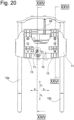
- the headrest 60 differs from the headrest 30 only in that a first electric drive device 61 is provided for adjusting the head box 11 in the direction z1 and z2 and a second electric drive device 62 is provided for adjusting the headrest part 13 in the direction x1 and x2. Due to the self-locking of the drive devices 61 and 62, no separate locking device 33 and no arresting device 44 corresponding to the headrest 30 are provided in the headrest 60.
- the drive device 61 comprises a first motor 63, which is an electric motor, which is attached to the head box 11.
- the motor 63 can drive a spindle nut (not shown) that is engaged with a first spindle 64 in the rotational directions m1 and m2.
- the spindle nut is rotatably held on the head box 11.
- the spindle 64 is engaged with the spindle nut at an end region 65.
- the spindle 64 is firmly and immovably connected to the cross member 32 at an end region 66 by means of a fastening 67.
- the spindle nut When the spindle nut is rotated by the motor 63 in the direction m1, it screws on the spindle 64 in the direction z1 and the head box 11 moves in z1 along the support rod ends 12a and 12b. If, on the other hand, the spindle nut is moved by the motor 63 in the direction m2, it screws on the spindle 64 in the direction z2 and the head box 11 moves in the direction z2 relative to the support rod ends 12a and 12b.
- An actuation associated with the drive device 61 can be arranged on the vehicle seat on which the headrest 60 is held or at another location in the vehicle interior, by means of which the motor 63 can be controlled, i.e. with which the motor is switched on and off and the direction of rotation is determined.
- the second drive device 62 for driving the head support part 13 comprises a second motor 68, which is an electric motor and which drives a spindle nut (not shown) in the directions of rotation n1 and n2.
- the spindle nut is in engagement with a second spindle 69.
- An end region 70 of the second spindle 69 is fixedly and immovably connected to a plate 72 of the head support part 13 by means of a fastening 71.
- An end region 73 of the second spindle 69 is in engagement with the second spindle nut.
- the spindle 69 and the head support part 13 attached to it move in the direction x1. If the spindle nut rotates in the opposite direction n2, the spindle 69 and the head support part 13 move in the direction x2.
- An actuation associated with the drive device 62 can be arranged on the vehicle seat on which the headrest 60 is held or at another location in the vehicle interior, by means of with which the motor 68 can be controlled, ie with which the motor is switched on and off and the direction of rotation is determined.
Landscapes
- Engineering & Computer Science (AREA)
- Aviation & Aerospace Engineering (AREA)
- Transportation (AREA)
- Mechanical Engineering (AREA)
- Chair Legs, Seat Parts, And Backrests (AREA)
- Seats For Vehicles (AREA)
- Accommodation For Nursing Or Treatment Tables (AREA)
Description
- Die Erfindung betrifft eine Kopfstütze. Eine solche Kopfstütze weist einen Kopfkasten auf, welcher mittels wenigstens einer Tragstange an der Rückenlehne eines Fahrzeugsitzes lagerbar ist. Ein Kopfanlageteil ist relativ zu dem Kopfkasten zwischen einer hinteren, vom Kopf eines Sitzinsassen wegbewegten Position und einer vorderen, dem Kopf angenäherten Position, bewegbar.
- Eine solche Kopfstütze ist aus der
DE 10 2009 038 631 A1 bekannt. Bei dieser Kopfstütze ist das Kopfanlageteil von zwei Zahnrädern, die um vertikale Achsen drehbar sind und einem Zahnrad, welches um eine horizontale Achse drehbar ist, geführt. -
EP 1 134 114 A2 betrifft einer Kopfstütze mit einem Kopfanlageteil, welches bei dem Ausführungsbeispiel, das in denFig. 7 und8 dargestellt und in Absatz 17 beschrieben ist, geschwenkt und in horizontalter Richtung sowie in vertikaler Richtung bewegt wird. Das Kopfanlageteil ist an einem Halteelement 16 gelagert. - Die Schwenkvorrichtung 20 weist zwei Paare von konzentrisch zur Drehachse 21 angeordneten voneinander radial beabstandeten Zahnsegmenten 37, 38 auf, deren Zahnreihen einander zugekehrt sind, sowie zwei Paare von jeweils mit einem der Zahnsegmente 37, 38 kämmenden Zahnrädern 39, 40 auf. Die insgesamt vier Zahnsegmente 37 und 38 sind an dem Kopfanlageteil befestigt, während die insgesamt vier Zahnräder 39 und 40 drehbar an dem Halteelement gelagert sind. Dabei sitzen die beiden mit den Zahnsegmenten 37 kämmenden Zahnräder 39 und die beiden mit den Zahnsegmenten 38 kämmenden Zahnräder 40 jeweils auf einer gemeinsamen Welle 41 bzw. 42. Auf der Zahnradwelle 43 sitzt außerdem noch ein Antriebszahnrad 43 sowie ein Handrad 44. Das Antriebszahnrad 43 kämmt mit dem Zahnrad 43.
-
WO 2011/032702 A1 beschreibt eine Kopfstütze, die drei Führungselemente 5 aufweist, die dreieckförmig angeordnet und in Führungsmitteln 18 gelagert sind. Diese drei Führungselemente werden mittels der beiden Zahnräder 18 miteinander synchronisiert. diese Zahnräder 22 kämmen miteinander und das obere Zahnrad 22 ist drehfest mit einer Welle verbunden, auf der ebenfalls drehfest Zahnräder angeordnet sind, die mit Zahnstangen, die an den Führungselementen 5 vorgesehen sind, kämmen. - Es war Aufgabe der Erfindung eine andere vorteilhafte Kopfstütze mit einem einfachen Aufbau und einer soliden Führung zu schaffen.
- Die Aufgabe wurde gelöst durch eine Kopfstütze mit den Merkmalen des Anspruchs 1.
- Die erfindungsgemäße Kopfstütze umfasst einen Kopfkasten, welcher an wenigstens einer Tragstange, insbesondere an zwei Tragstangen, gehalten ist. Der Kopfkasten kann relativ zu der Tragstange unbeweglich oder beweglich gelagert sein. Im Falle der beweglichen Lagerung ist der Kopfkasten z.B. höhenverstellbar an der Tragstange gelagert. Die Tragstange ist an einem Fahrzeugsitz, insbesondere an der Rückenlehne eines Fahrzeugsitzes lagerbar. Dafür weist der Fahrzeugsitz Führungen zur Lagerung und Befestigung der Tragstangen auf. Die Tragstange kann z.B. in verschiedenen Relativpositionen zu den Führungen höhenverstellbar und in diesen Positionen arretierbar sein.
- Ein Kopfanlageteil ist mittels einer primären Führungsvorrichtung relativ zu dem Kopfkasten in horizontaler Richtung zwischen einer von dem Kopf eines Sitzinsassen wegbewegten hinteren Position und einer dem Kopf angenäherten vorderen Position verstellbar. Dafür sind an dem Kopfkasten erste Führungsmittel ausgebildet, die mit zweiten Führungsmitteln des Kopfanlageteils zusammenwirken und die Verstellung zwischen der hinteren und der vorderen Position ermöglichen.
- Dabei umfassen die einen Führungsmittel zwei horizontal voneinander beabstandete sich in Bewegungsrichtung des Kopfanlageteils erstreckende Zahnschienen, die ein erstes Zahnschienenpaar bilden. Die anderen Führungsmittel umfassen zwei horizontal voneinander beabstandete Zahnräder, die ein erstes Zahnradpaar bilden, wobei jedes Zahnrad mit einer Zahnschiene in Eingriff steht und bei der Bewegung des Kopfanlageteils zwischen der hinteren Position und der vorderen Position auf der Zahnschiene abrollt. Die Zahnräder sind z.B. mit einer Welle fest verbunden und somit untereinander drehverbunden oder mit anderen Worten gekoppelt. Gemäß einer Alternative sind die Zahnräder des ersten Zahnradpaares nicht mittels einer Welle gekoppelt, sondern einzeln an dem Kopfkasten drehbar gelagert.
- Weiterhin umfassen die einen Führungsmittel zwei horizontal voneinander beabstandete sich in Bewegungsrichtung des Kopfanlageteils erstreckende Zahnschienen, die ein zweites Zahnschienenpaar bilden, welches sich parallel zu dem ersten Zahnschienenpaar erstreckt und diesem zugewandt ist. Mit jeder Zahnschiene des zweiten Zahnschienenpaares steht ein Zahnrad eines zweiten Zahnradpaares in Eingriff, welches zwei horizontal voneinander beabstandete Zahnräder umfasst. Die Zahnräder des zweiten Zahnradpaares sind z.B. mit einer Welle fest verbunden und somit miteinander drehverbunden. Gemäß einer Alternative sind die Zahnräder des zweiten Zahnradpaares nicht mittels einer Welle gekoppelt, sondern einzeln an dem Kopfkasten drehbar gelagert.
- Jeweils ein Zahnrad des ersten Zahnradpaares steht weiterhin mit einem Zahnrad des zweiten Zahnradpaares in Eingriff. Dabei ist es möglich, dass lediglich eines der Zahnradpaare mit einer Welle gekoppelt ist und jedes Zahnrad dieses gekoppelten Zahnradpaares treibt ein Zahnrad des anderen Zahnradpaares an. Auf diese Weise ist eine Führung des Kopfanlageteils in zwei Raumrichtungen gewährleistet und ein ungewolltes Schwenken des Kopfanlageteils um jede der drei Raumachsen wird verhindert.
- Die Kopfstütze ist z.B. mit einer Arretiervorrichtung versehen, welche dem Kopfkasten zugeordnete erste Arretiermittel und dem Kopfanlageteil zugeordnete zweite Arretiermittel umfasst. Die Arretiervorrichtung ist zwischen einer Arretierposition, in welcher die ersten Arretiermittel und die zweiten Arretiermittel in Eingriff stehen und einer Löseposition, in welcher die ersten Arretiermittel und die zweiten Arretiermittel außer Eingriff stehen, bewegbar. In der Arretierposition ist eine Bewegung des Kopfanlageteils in wenigstens eine Richtung nicht möglich. D.h. das Kopfanlageteil kann in eine Richtung bewegbar sein und in eine andere Richtung nicht bewegbar sein oder alternativ in beide Richtungen nicht bewegbar sein. In der Löseposition ist eine Bewegung des Kopfanlageteils in beide Richtungen möglich.
- Der Kopfkasten ist z.B. mittels einer sekundären Führungsvorrichtung bewegbar an der Tragstange gelagert und mittels einer Verriegelungsvorrichtung in wenigstens einer Position verriegelbar. Der Kopfkasten kann z.B. Gleitlager aufweisen, mittels denen er an den Tragstangen gleitgelagert ist. Auf diese Weise ist der Kopfkasten z.B. in vertikaler Richtung verstellbar.
- Die Verriegelungsvorrichtung umfasst z.B. wenigstens einen Rigel, welcher dem Kopfkasten zugeordnet ist, wobei der Riegel zwischen einer Riegelposition und einer Freigabeposition bewegbar ist. In der Riegelposition steht der Riegel in Eingriff mit einer Kerbe einer Anordnung von Kerben der Tragstange, wobei die Anordnung wenigstens eine Kerbe umfasst. In der Freigabeposition ist der Riegel außer Eingriff mit der Anordnung. In der Riegelposition ist eine Bewegung des Kopfkastens in wenigstens eine Richtung nicht möglich. D.h. die Bewegung des Kopfkastens ist z.B. in eine Richtung möglich, in eine andere Richtung hingegen nicht möglich oder gemäß einer Alternative, in beide Bewegungsrichtungen nicht möglich.
- Der Riegel kann z.B. von einer Rückstellkraft in die Riegelposition belastet sein. Die Rückstellkraft kann daraus resultieren, dass der Riegel elastisch verformbar ist und sich in die Ausgangsform zurückstellt. Alternativ kann die Rückstellkraft z.B. von einem gesonderten Federelement aufgebracht werden.
- Das Kopfanlageteil ist z.B. von einer Feder in die hintere Position belastet. Bei der Feder kann es sich z.B. um eine Schraubenfeder handeln, wobei ein Federende mit der Welle eines Zahnradpaares verbunden ist und ein anderes Federende mit dem Kopfkasten verbunden ist.
- An dem Kopfkasten ist z.B. ein Verstellteil bewegbar gelagert. Das Verstellteil kann z.B. Teil der Verriegelungsvorrichtung und / oder der Arretiervorrichtung sein. Das Verstellteil ist zwischen einer ersten Position und einer zweiten Position bewegbar. Es kann translatorisch und / oder rotatorisch bewegbar sein. Das Verstellteil kann z.B. von einem Schieber gebildet sein. Der Schieber ist z.B. als Platte ausgebildet. Die Platte ist z.B. parallel zu einer von den Tragstangenenden aufgespannten Ebene bewegbar.
- Z.B. sind die ersten Arretiermittel dem Verstellteil zugeordnet. Das Verstellteil weist z.B. wenigstens einen Arretierbereich auf, der lösbar in Eingriff mit den zweiten Arretiermitteln bewegbar ist. Bei den zweiten Arretiermitteln handelt es sich z.B. um eine Verzahnung.
- Das Verstellteil ist z.B. Teil der Verriegelungsvorrichtung. Es umfasst z.B. Betätigungsmittel, die den Riegel zwischen der Riegelposition und der Freigabeposition bewegen.
- Weitere Vorteile der Kopfstütze ergeben sich anhand der Beschreibung von in den Figuren dargestellten Ausführungsbeispielen. Es zeigen:
-
Fig. 1 eine perspektivische Darstellung einer ersten Ausführungsform der erfindungsgemäßen Kopfstütze, wobei das Kopfanlageteil nur teilweise dargestellt ist und sich in einer hinteren Position befindet, -
Fig. 2 in Anlehnung anFig. 1 die Kopfstütze, wobei das Kopfanlageteil in der vorderen Position angeordnet ist, -
Fig. 2a eine Frontansicht der Kopfstütze, wobei das Kopfanlageteil in der hinteren Position angeordnet ist. -
Fig. 3 eine Schnittdarstellung gemäß Schnittlinie III - III inFig. 2a . -
Fig. 4 eine Schnittdarstellung in Anlehnung anFig. 3 , wobei sich das Kopfanlageteil in der vorderen Position befindet, -
Fig. 5 in Anlehnung an die Schnittdarstellung derFig. 3 eine andere Ausführungsform, wobei lediglich ein durch eine Welle verbundenes Zahnradpaar zur Führung vorgesehen ist und wobei sich das Kopfanlageteil in der hinteren Position befindet, -
Fig. 6 in Anlehnung anFig. 5 die zweite Ausführungsform, wobei sich das Kopfanlageteil in der vorderen Position befindet, -
Fig. 7 eine perspektivische Darstellung einer dritten Ausführungsform der Kopfstütze, wobei das Kopfanlageteil nur teilweise dargestellt und ein Polster nicht dargestellt ist und sich das Kopfanlageteil in der hinteren Position befindet, -
Fig. 8 in Anlehnung anFig. 7 die Kopfstütze, wobei sich das Kopfanlageteil in der vorderen Position befindet, -
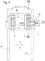
Fig. 9 eine Frontansicht der Kopfstütze gemäßFig. 7 , -
Fig. 10 eine rückwärtige Ansicht der Kopfstütze gemäßFig. 7 , -
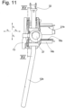
Fig. 11 eine Seitenansicht gemäß Ansichtspfeil XI inFig. 9 , -
Fig. 12 in Anlehnung anFig. 11 eine Seitenansicht, wobei sich das Kopfanlageteil in der vorderen Position befindet, -
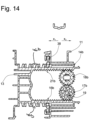
Fig. 13 eine Schnittdarstellung gemäß Schnittlinie XIII - XIII inFig. 9 , -
Fig. 14 in Anlehnung anFig. 13 eine Schnittdarstellung, wobei sich das Kopfanlageteil in der vorderen Position befindet, -
Fig. 15 eine Schnittdarstellung gemäß Schnittlinie XV - XV inFig. 11 , wobei sich ein Schieber in einer ersten Position befindet, -
Fig. 16 in Anlehnung anFig. 15 eine Schnittdarstellung, wobei sich der Schieber in einer zweiten Position befindet, -
Fig. 17 eine Schnittdarstellung gemäß Schnittlinie XVII - XVII inFig. 10 , -
Fig. 18 eine perspektivische Darstellung eines vierten Ausführungsbeispiels der erfindungsgemäßen Kopfstütze, wobei ein Kopfanlageteil nur teilweise und das Kopfpolster nicht dargestellt sind und wobei das Kopfanlageteil in der hinteren Position angeordnet ist, -
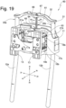
Fig. 19 in Anlehnung anFig. 18 die Kopfstütze, wobei sich das Kopfanlageteil in der vorderen Position befindet, -
Fig. 20 eine Frontansicht der Kopfstütze, wobei sich das Kopfanlageteil in der hinteren Position befindet, -
Fig. 21 eine rückwärtige Ansicht der Kopfstütze gemäßFig. 20 , -
Fig. 22 eine Seitenansicht der Kopfstütze gemäß Ansichtspfeil XXII inFig. 20 , -
Fig. 23 in Anlehnung anFig. 22 eine Seitenansicht, wobei sich das Kopfanlageteil in der vorderen Position befindet, -
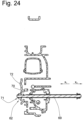
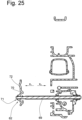
Fig. 24 eine Schnittdarstellung gemäß Schnittlinie XXIV - XXIV inFig. 20 , -
Fig. 25 in Anlehnung anFig. 24 die Schnittdarstellung, wobei sich das Kopfanlageteil in der vorderen Position befindet, -
Fig. 26 eine Schnittdarstellung gemäß Schnittlinie XXVI - XXVI inFig. 20 , -
Fig. 27 in Anlehnung anFig. 26 die Schnittdarstellung, wobei sich das Kopfanlageteil in der vorderen Position befindet. - Eine Kopfstütze insgesamt ist in den Fig. mit dem Bezugszeichen 10 bezeichnet. Gleiche Bezugszeichen in den Fig. bezeichnen entsprechende Teile.
- Die Kopfstütze 10 umfasst einen Kopfkasten 11 und Tragstangenenden 12a und 12b, mit denen die Kopfstütze 10 an der Rückenlehne eines nicht dargestellten Fahrzeugsitzes befestigt werden kann. Ein Kopfanlageteil 13 ist lediglich teilweise dargestellt, wobei eine Kopfanlageplatte in den Fig. nicht gezeigt ist. Das Kopfanlageteil 13 ist zwischen einer in
Fig. 1 und3 dargestellten hinteren Position und einer inFig. 2 und4 dargestellten vorderen Position bewegbar. - Ein hinterer Fortsatz 14 des Kopfanlageteils 13 umfasst gemäß dem ersten Ausführungsbeispiel untere etwa horizontale Platten 15a und 15b an denen jeweils eine Zahnschiene 16a und 16b ausgebildet ist. Die Zähne der Zahnschienen 16a und 16b weisen in Richtung z1. Die Zahnstrukturen der Zahnschienen 16a und 16b erstrecken sich in Richtung x1, x2, d.h. in Bewegungsrichtung des Kopfanlageteils. An dem Kopfkasten 11 sind mittels einer Welle 19 Zahnräder 17a und 17b gelagert. Die Zahnräder 17a und 17b sind mittels der Welle 19 bewegungsverbunden. Die Welle 19 ist etwa parallel zu einer y-Achse angeordnet. Das Zahnrad 17a steht mit der Zahnschiene 16a und das Zahnrad 17b mit der Zahnschiene 16b in Eingriff und rollt bei der Bewegung des Kopfanlageteils 13 zwischen der hinteren und der vorderen Position auf dieser ab.
- In Richtung z1 befindet sich über dem Zahnrad 17a ein Zahnrad 18a und über dem Zahnrad 17b ein Zahnrad 18b. Die Zahnräder 17a und 18a und die Zahnräder 17b und 18b stehen in Eingriff miteinander. Die Zahnräder 18a und 18b sind an dem Kopfkasten 11 gelagert und sind nicht miteinander bewegungsverbunden. Eine geometrische Drehachse a der Zahnräder 18a und 18b ist parallel zu der y-Achse angeordnet.
- Der Fortsatz 14 des Kopfanlageteils 13 umfasst ferner obere etwa horizontale Platten 20a und 20b an denen eine Zahnschiene 21a und 21b ausgebildet ist. Die Zähne der Zahnschienen 21a und 21b weisen in Richtung z2. Die Zahnstruktur der Zahnschienen 21a und 21b erstrecken sich in Richtung x1, x2, d.h. in Bewegungsrichtung des Kopfanlageteils. Das Zahnrad 18a steht mit der Zahnschiene 21a und das Zahnrad 18b mit der Zahnschiene 21b in Eingriff. Die Zahnräder 18a und 18b rollen bei der Bewegung des Kopfanlageteils 13 zwischen der hinteren und der vorderen Position auf den Zahnschienen 21a bzw. 21b ab.
- Auf diese Weise kann sich das Kopfanlageteil 13 in die Richtungen x1 und x2 bewegen, ein Verdrehen des Kopfanlageteils um die x-, y- und z-Achse wird aber verhindert.
- Ein zweites Ausführungsbeispiel ist in den
Fig. 5 und 6 dargestellt. Es unterscheidet sich von dem ersten Ausführungsbeispiel nur dadurch, dass die Zahnräder 18a und 18b nicht vorhanden sind. - Ein drittes Ausführungsbeispiel einer Kopfstütze 30 ist in den
Fig. 7 bis 18 dargestellt. Die Kopfstütze 30 umfasst einen Tragstangenbügel 31, welcher zwei Tragstangenenden 12a und 12b sowie eine die Tragstangenenden 12a und 12b verbindende Traverse 32 aufweist. An den Tragstangenenden 12a und 12b ist ein Kopfkasten 11 in die Richtungen z1 und z2 verstellbar geführt. Die freien Tragstangenenden 12a und 12b sind in korrespondierenden nicht dargestellten Führungen eines Fahrzeugsitzes lagerbar. - Mittels einer Verriegelungsvorrichtung 33 kann der Kopfkasten 11 in unterschiedlichen Höhenpositionen verriegelt werden. Die Verriegelungsvorrichtung 33 umfasst einen am Kopfkasten 11 gehaltenen Riegel 34a, der mit einer Anordnung von Kerben 35a zusammenwirkt sowie einen am Kopfkasten 11 gehaltenen Riegel 34b, der mit einer Anordnung von Kerben 35b zusammenwirkt.
- In der Riegelposition greift der Riegel 34a in eine der Kerben der Anordnung 35a und der Riegel 34b greift in eine der Kerben der Anordnung 35b. Auf diese Weise wird eine Bewegung des Kopfkastens 11 in Richtung z2 verhindert. Aufgrund der Form der Kerben der Anordnungen 35a und 35b ist eine Bewegung des Kopfkastens 11 in Richtung z1 möglich. In der Freigabeposition sind die Riegel 34a und 34b außer Eingriff mit den Anordnungen 35a und 35b, d.h. die Riegel 34a und 34b greifen in keine der Kerben ein. Gemäß einer alternativen Ausführung könnten die Kerben auch so gestaltet sein, dass in der Riegelposition eine Bewegung in Richtung z1 und z2 verhindert wird.
- Mit einer Betätigungsvorrichtung 36 kann die Verriegelungsvorrichtung 33 von der Riegelposition in die Freigabeposition bewegt werden. Die Verriegelungsvorrichtung 33 ist von einer Rückstellkraft in die Riegelposition belastet. Die Betätigungsvorrichtung 36 umfasst eine Handhabe 37 die mit einem Schieber 38 bewegungsverbunden ist. Wenn die Handhabe 37 in Richtung y1 bewegt wird, verlagert sie den Schieber 38 ebenfalls in Richtung y1. Der Schieber 38 drückt bei seiner Bewegung in Richtung y1 die Riegel 34a und 34b außer Eingriff mit den Anordnungen 35a und 35b und verstellt damit die Verriegelungsvorrichtung 33 in die Freigabeposition.
- Der Schieber 38 ist von einer Platte gebildet, die etwa parallel zu einer von den Tragstangenenden 12a und 12b aufgespannten Ebene angeordnet ist und mittels einer Führung 39 an dem Kopfkasten 11 in die Richtungen y1 und y2 verlagerbar geführt ist. Von einem nicht dargestellten Rückstellelement ist der Schieber 38 in Richtung y2 belastet.
- Das Kopfanlageteil 13 ist mit zwei Fortsätzen 14a und 14b versehen, die sich jeweils von dem Kopfanlageteil 13 in eine Richtung x2 erstrecken. Die Fortsätze 14a und 14b stellen Führungsmittel bereit, die einer Lagervorrichtung 40 zur Lagerung und Führung des Kopfanlageteils 13 an dem Kopfkasten 11 zugeordnet sind. Entsprechend dem ersten Ausführungsbeispiel sind an dem Fortsatz 14a Zahnschienen 16a und 21a und an dem Fortsatz 14b Zahnschienen 16b und 21b ausgebildet.
- Die Zahnschienen 16 und 16b wirken in gleicher Weise, wie bei dem ersten Ausführungsbeispiel, mit durch eine Welle 19 verbundenen Zahnrädern 17a und 17b zusammen. Auch wirken die Zahnschienen 21a und 21b in gleicher Weise, wie bei dem ersten Ausführungsbeispiel, mit Zahnrädern 18a und 18b zusammen, die drehbar an dem Kopfkasten 11 gelagert sind. Außerdem stehen die Zahnräder 17a und 18a sowie die Zahnräder 17b und 18b in Eingriff miteinander. Die Längsachse der Welle 19 sowie eine geometrische Drehachse der Zahnräder 18a und 18b sind parallel zu der y-Achse angeordnet.
- Auf diese Weise ist das Kopfanlageteil 13 in Richtung x1 und x2 bewegbar an dem Kopfkasten 11 geführt und lässt sich weder um eine parallel zu den Richtungen z1 und z2 ausgebildeten z-Achse noch um eine parallel zu den Richtungen y1 und y2 ausgebildeten y-Achse noch um eine parallel zu den Richtung x1 und x2 ausgebildete x-Achse drehen.
- Die hintere, maximal zurückgezogene Position des Kopfanlageteils 13 ist in den
Fig. 7 ,9 ,11 und13 dargestellt, während die vordere, maximal vorgeschobene Position in denFig. 8 ,12 und14 dargestellt ist. In der rückwärtigen Ansicht der Kopfstütze 30 gemäßFig. 10 ist erkennbar, dass auf der Welle 19 eine Schraubenfeder 41 angeordnet ist, wobei ein erstes Federende 42 an der Welle 19 befestigt ist und ein zweites Federende 43 an dem Kopfkasten 11 befestigt ist. Die Welle 19 wird von der Feder 41 in Drehrichtung u1 und somit wird das Kopfanlageteil 13 in Richtung x2 belastet. Eine Bewegung der Welle 19 in Drehrichtung u2 spannt die Feder 41. - Eine Arretiervorrichtung 44 umfasst erste dem Kopfkasten 11 zugeordnete Arretiermittel sowie zweite, dem Kopfanlageteil 13 zugeordnete Arretiermittel. Die ersten Arretiermittel sind von Riegelbereichen 45a und 45b des Schiebers 38 gebildet. Der Schieber umfasst zwei Öffnungen 47a und 47b, wobei die Öffnung 47a von dem Fortsatz 14a und die Öffnung 47b von dem Fortsatz 14b durchsetzt ist. An der Laibung der Öffnung 47a ist eine Arretierbereich 45a und an der Laibung der Öffnung 47b ein Arretierbereich 45b angeordnet. An dem Fortsatz 14a ist eine Verzahnung 48a und an dem Fortsatz 14b ist eine Verzahnung 48b ausgebildet.
- Wenn die Riegelbereiche 45a und 45b in der Arretierposition mit den Verzahnungen 48a und 48b in Eingriff stehen ist eine Bewegung des Kopfanlageteils in die Richtungen x1 und x2 (oder nur in Richtung x2?) nicht möglich. Sobald die Handhabe 37 in Richtung y1 betätigt wird bewegt sich der Schieber 38 in Richtung y1. Dabei werden die Riegelbereiche 45a und 45b außer Eingriff mit den Verzahnungen 48a und 48b bewegt. Die Arretiervorrichtung befindet sich dann in der Löseposition und das Kopfanlageteil kann manuell in die Richtungen x1 oder x2 bewegt werden.
- Wenn die Handhabe 37 nicht mehr betätigt wird, verlagert die nicht dargestellte Feder den Schieber 38 in Richtung y2, wobei die Arretierbereiche 45a und 45b gegen die Fortsätze 14a und 14b in Eingriff mit den Verzahnungen 48a und 48b belastet werden. Dabei kann das Kopfanlageteil 13 eine Position aufweisen, in welcher die Arretierbereiche 45a und 45b nicht unmittelbar in eine der Aussparungen der Verzahnungen 48a und 48b eingreifen können. Aufgrund der Rückstellbelastung des Kopfanlageteils 13 mittels der Feder 41 in Richtung x2 bewegt sich das Kopfanlageteil 13 soweit in Richtung x2, bis die Arretierbereiche 45a und 45b in eine der Aussparungen 46a und 46b der Verzahnungen 48a und 48b eingreifen.
- Ein viertes Ausführungsbeispiel ist in den
Fig. 18 bis 27 dargestellt. Eine Kopfstütze gemäß dem vierten Ausführungsbeispiel ist in den Fig. mit dem Bezugszeichen 60 bezeichnet. Die Kopfstütze 60 gemäß dem vierten Ausführungsbeispiel ist prinzipiell wie die Kopfstütze 30 gemäß dem dritten Ausführungsbeispiel ausgebildet. - Die Kopfstütze 60 unterscheidet sich von der Kopfstütze 30 lediglich dadurch, dass eine erste elektrische Antriebsvorrichtung 61 für eine Verstellung des Kopfkastens 11 in Richtung z1 und z2 sowie eine zweite elektrische Antriebsvorrichtung 62 für eine Verstellung des Kopfanlageteils 13 in Richtung x1 und x2 vorgesehen ist. Aufgrund der Selbsthemmung der Antriebsvorrichtungen 61 und 62 ist bei der Kopfstütze 60 keine gesonderte Verriegelungsvorrichtung 33 und keine Arretiervorrichtung 44 entsprechend der Kopfstütze 30 vorgesehen.
- Die Antriebsvorrichtung 61 umfasst einen ersten Motor 63, der ein Elektromotor ist, welcher an dem Kopfkasten 11 befestigt ist. Der Motor 63 kann eine mit einer ersten Spindel 64 in Eingriff stehende, nicht dargestellte Spindelmutter in die Drehrichtungen m1 und m2 antreiben. Die Spindelmutter ist drehbar an dem Kopfkasten 11 gehalten. Die Spindel 64 ist mit einem Endbereich 65 mit der Spindelmutter in Eingriff. Mit einem Endbereich 66 ist die Spindel 64 mit einer Befestigung 67 fest, unbeweglich mit der Traverse 32 verbunden.
- Wenn die Spindelmutter von dem Motor 63 in Richtung m1 gedreht wird, schraubt sie sich auf der Spindel 64 in Richtung z1 und der Kopfkasten 11 bewegt sich in z1 entlang der Tragstangenenden 12a und 12b. Wird die Spindelmutter hingegen von dem Motor 63 in Richtung m2 bewegt, schraubt sie sich auf der Spindel 64 in Richtung z2 und der Kopfkasten 11 bewegt sich in Richtung z2 relativ zu den Tragstangenenden 12a und 12b.
- An dem Fahrzeugsitz, an welchem die Kopfstütze 60 gehalten ist oder und an einem anderen Ort im Fahrzeuginnenraum kann eine der Antriebsvorrichtung 61 zugeordnete Betätigung angeordnet sein, mittels welcher der Motor 63 gesteuert werden kann, d.h., mit welcher der Motor an- und ausgeschaltet und die Drehrichtung festgelegt wird.
- Die zweite Antriebsvorrichtung 62 zum Antrieb des Kopfanlageteils 13 umfasst einen zweiten Motor 68, der ein Elektromotor ist, und der eine nicht dargestellte Spindelmutter in die Drehrichtungen n1 und n2 antreibt. Die Spindelmutter steht mit einer zweiten Spindel 69 in Eingriff. Ein Endbereich 70 der zweiten Spindel 69 ist mittels einer Befestigung 71 an einer Platte 72 des Kopfanlageteils 13 fest, unbeweglich verbunden. Ein Endbereich 73 der zweiten Spindel 69 steht mit der zweiten Spindelmutter in Eingriff.
- Wird die Spindelmutter von dem zweiten Motor 68 in Richtung n1 gedreht, so bewegen sich die Spindel 69 und das daran befestigte Kopfanlageteil 13 in Richtung x1. Bei umgekehrter Drehrichtung n2 der Spindelmutter, bewegen sich die Spindel 69 und das Kopfanlageteil 13 in Richtung x2.
- An dem Fahrzeugsitz, an dem die Kopfstütze 60 gehalten ist oder und an einem anderen Ort im Fahrzeuginnenraum kann eine der Antriebsvorrichtung 62 zugeordnete Betätigung angeordnet sein, mittels welcher der Motor 68 gesteuert werden kann, d.h., mit welcher der Motor an- und ausgeschaltet und die Drehrichtung festgelegt wird.
Claims (10)
- Kopfstütze mit einem Kopfkasten(11), welcher an wenigstens einer Tragstange (12a, 12b) gehalten ist und mittels der Tragstange (12a, 12b) an der Rückenlehne eines Fahrzeugsitzes lagerbar ist, mit einem Kopfanlageteil (13), welches mittels einer primären Führungsvorrichtung relativ zu dem Kopfkasten (11) in horizontaler Richtung (x1, x2) zwischen einer von dem Kopf eines Sitzinsassen wegbewegten hinteren Position und einer dem Kopf angenäherten vorderen Position verstellbar ist, dass der Kopfkasten (11) erste Führungsmittel aufweist, die mit zweiten Führungsmitteln des Kopfanlageteils (13) zusammenwirken, wobei die einen Führungsmittel zwei horizontal voneinander beabstandete sich in Bewegungsrichtung des Kopfanlageteils erstreckende Zahnschienen (16a, 16b) umfassen, die ein erstes Zahnschienenpaar bilden und zwei horizontal voneinander beabstandete sich in Bewegungsrichtung des Kopfanlageteils erstreckende Zahnschienen (21a, 21b) umfassen, die ein zweites Zahnschienenpaar bilden, welches sich parallel zu dem ersten Zahnschienenpaar erstreckt und diesem zugewandt ist, wobei die anderen Führungsmittel zwei horizontal voneinander beabstandete Zahnräder (17a, 17b) umfassen, die ein erstes Zahnradpaar bilden, wobei jedes Zahnrad (17a, 17b) des ersten Zahnradpaares mit einer Zahnschiene (16a, 16b) des ersten Zahnschienenpaares in Eingriff steht und dass mit jeder Zahnschiene (21a, 21b) des zweiten Zahnschienenpaares ein Zahnrad (18a, 18b) eines zweiten Zahnradpaares in Eingriff steht, welches zwei horizontal voneinander beabstandete Zahnräder umfasst, wobei die Zahnräder (17a, 17b) des ersten Zahnradpaares und / ' oder die Zahnräder (18a, 18b) des zweiten Zahnradpaares mit einer Welle (19) bewegungsverbunden sind und wobei jedes Zahnrad bei der Bewegung des Kopfanlageteils (13) zwischen der hinteren Position und der vorderen Position auf der Zahnschiene (16a, 16b) abrollt, dadurch gekennzeichnet, dass jeweils ein Zahnrad (17a, 17b) des ersten Zahnradpaares mit einem Zahnrad (18a, 18b) des zweiten Zahnradpaares in Eingriff steht.
- Kopfstütze nach Anspruch 1, dadurch gekennzeichnet, dass eine Arretiervorrichtung (44) dem Kopfkasten (11) zugeordnete erste Arretiermittel und dem Kopfanlageteil (13) zugeordnete zweite Arretiermittel umfasst.
- Kopfstütze nach Anspruch 2, dadurch gekennzeichnet, dass die Arretiervorrichtung zwischen einer Arretierposition, in welcher die ersten Arretiermittel und die zweiten Arretiermittel in Eingriff stehen und einer Löseposition, in welcher die ersten Arretiermittel und die zweiten Arretiermittel außer Eingriff stehen, bewegbar ist.
- Kopfstütze nach einem der vorangegangenen Ansprüche, dadurch gekennzeichnet, dass der Kopfkasten (11) mittels einer sekundären Führungsvorrichtung bewegbar an einer Tragstange (12a, 12b) gelagert ist und mittels einer Verriegelungsvorrichtung (33) in wenigstens einer Position verriegelbar ist.
- Kopfstütze nach Anspruch 4, dadurch gekennzeichnet, dass die Verriegelungsvorrichtung (33) einen Riegel (34a, 34b) umfasst, welcher dem Kopfkasten (11) zugeordnet ist, wobei der Riegel zwischen einer Riegelposition und einer Freigabeposition bewegbar ist.
- Kopfstütze nach Anspruch 5, dadurch gekennzeichnet, dass ein Verstellteil (38) den Riegel (34a, 34b) zwischen der Riegelposition und der Freigabeposition bewegt.
- Kopfstütze nach Anspruch 6, soweit auf einen der Ansprüche 2 oder 3 zurückbezogen, dadurch gekennzeichnet, dass die ersten Arretiermittel dem Verstellteil (38) zugeordnet sind.
- Kopfstütze nach einem der Ansprüche 6 oder 7, dadurch gekennzeichnet, dass das Verstellteil (38) an dem Kopfkasten (11) bewegbar gelagert ist.
- Kopfstütze nach einem der vorangegangenen Ansprüche, dadurch gekennzeichnet, dass das Kopfanlageteil (13) von einer Feder (41) in eine erste Richtung (x1) oder in eine zweite Richtung (x2) belastet ist.
- Kopfstütze nach einem der vorangegangenen Ansprüche, dadurch gekennzeichnet, dass wenigstens eine elektrische Antriebsvorrichtung (63, 64, 68, 69) vorgesehen ist, mittels welcher das Kopfanlageteil (13) relativ zu dem Kopfkasten (11) und / oder der Kopfkasten (11) relativ zu der Tragstange (12a, 12b) bewegbar ist und dass die Antriebsvorrichtung das Kopfanlageteil und / oder den Kopfkasten in der jeweiligen Relativposition hält.
Applications Claiming Priority (2)
| Application Number | Priority Date | Filing Date | Title |
|---|---|---|---|
| DE102014015205 | 2014-10-16 | ||
| PCT/DE2015/000511 WO2016058581A1 (de) | 2014-10-16 | 2015-10-16 | Kopfstütze für einen fahrzeugsitz |
Publications (2)
| Publication Number | Publication Date |
|---|---|
| EP3206908A1 EP3206908A1 (de) | 2017-08-23 |
| EP3206908B1 true EP3206908B1 (de) | 2025-02-19 |
Family
ID=54478529
Family Applications (1)
| Application Number | Title | Priority Date | Filing Date |
|---|---|---|---|
| EP15791485.4A Active EP3206908B1 (de) | 2014-10-16 | 2015-10-16 | Kopfstütze für einen fahrzeugsitz |
Country Status (4)
| Country | Link |
|---|---|
| EP (1) | EP3206908B1 (de) |
| CN (1) | CN107000619A (de) |
| DE (1) | DE102015013362B4 (de) |
| WO (1) | WO2016058581A1 (de) |
Families Citing this family (8)
| Publication number | Priority date | Publication date | Assignee | Title |
|---|---|---|---|---|
| DE102016123837A1 (de) * | 2016-12-08 | 2018-06-14 | Brose Fahrzeugteile Gmbh & Co. Kommanditgesellschaft, Coburg | Spindelversteller |
| CN107284303B (zh) * | 2017-05-26 | 2023-04-18 | 安道拓(重庆)汽车部件有限公司 | 具有前后伸缩功能的汽车座椅头枕 |
| DE102018009229B4 (de) * | 2018-11-26 | 2021-09-02 | Grammer Aktiengesellschaft | Fahrzeugausstattungsteil |
| DE102018221622B3 (de) | 2018-12-13 | 2019-10-24 | Magna Seating (Germany) Gmbh | Verstellbare Kopfstützenanordnung für einen Kraftfahrzeugsitz |
| DE102018221626B3 (de) | 2018-12-13 | 2019-10-24 | Magna Seating (Germany) Gmbh | Verstellbare Kopfstützenanordnung für einen Kraftfahrzeugsitz |
| DE102019100156B4 (de) | 2019-01-07 | 2021-12-09 | Adient Engineering and IP GmbH | Kopfstütze für einen fahrzeugsitz sowie fahrzeugsitz |
| DE102019206543B4 (de) * | 2019-05-07 | 2023-01-12 | Magna Seating (Germany) Gmbh | Kopfstützenanordnung mit einem Antrieb zur horizontalen Verstellung eines Kopfstützenkastens für einen Kraftfahrzeugsitz |
| DE102024127048A1 (de) | 2024-09-19 | 2026-03-19 | Grammer Aktiengesellschaft | Kopfstütze für einen Fahrzeugsitz |
Family Cites Families (10)
| Publication number | Priority date | Publication date | Assignee | Title |
|---|---|---|---|---|
| DE3109592A1 (de) * | 1981-03-13 | 1982-10-28 | Eugen Otto 4010 Hilden Butz | Kopfstuetze fuer kraftfahrzeugsitze |
| DE10012973B4 (de) * | 2000-03-16 | 2004-02-26 | Daimlerchrysler Ag | Kopfstütze für einen Fahrzeugsitz |
| KR100387654B1 (ko) * | 2000-12-22 | 2003-06-18 | 현대자동차주식회사 | 자동차용 헤드레스트 가이드 장착구조 |
| KR100526790B1 (ko) * | 2003-08-16 | 2005-11-08 | 기아자동차주식회사 | 리어시트의 헤드레스트 이동장치 |
| JP2010036680A (ja) * | 2008-08-04 | 2010-02-18 | Nhk Spring Co Ltd | アクティブヘッドレストの傾動機構 |
| DE102009038631B4 (de) | 2008-11-14 | 2011-03-17 | Grammer Ag | Kopfstütze für Fahrzeugsitze |
| DE102009049946B4 (de) * | 2009-09-16 | 2015-04-02 | Johnson Controls Gmbh | In X-Richtung verstellbare Kopfstütze |
| CN103029605A (zh) * | 2011-10-08 | 2013-04-10 | 焦登科 | 一种可六向电动调整的车载座椅头枕机芯 |
| DE102012025191B3 (de) * | 2012-09-19 | 2014-01-23 | Johnson Controls Gmbh | Kopfstütze für einen Fahrzeugsitz |
| WO2015093529A1 (ja) * | 2013-12-18 | 2015-06-25 | テイ・エス テック株式会社 | ヘッドレスト |
-
2015
- 2015-10-16 EP EP15791485.4A patent/EP3206908B1/de active Active
- 2015-10-16 DE DE102015013362.4A patent/DE102015013362B4/de active Active
- 2015-10-16 CN CN201580063696.5A patent/CN107000619A/zh active Pending
- 2015-10-16 WO PCT/DE2015/000511 patent/WO2016058581A1/de not_active Ceased
Also Published As
| Publication number | Publication date |
|---|---|
| CN107000619A (zh) | 2017-08-01 |
| DE102015013362A1 (de) | 2016-04-21 |
| DE102015013362B4 (de) | 2025-12-24 |
| WO2016058581A1 (de) | 2016-04-21 |
| EP3206908A1 (de) | 2017-08-23 |
Similar Documents
| Publication | Publication Date | Title |
|---|---|---|
| DE102015013362B4 (de) | Kopfstütze für einen Fahrzeugsitz | |
| EP3597488B1 (de) | Kraftfahrzeug mit arretier- und kontaktierungssystem zum elektrischen verbinden eines bordnetzes eines kraftfahrzeugs mit einem entnehmbaren fahrzeugsitz oder einer sitzanlage | |
| EP2746100B1 (de) | Nutzfahrzeugsitz mit einem Verriegelungselement | |
| DE102012112527B3 (de) | Nutzfahrzeugsitz mit integrierter Drehverstelleinrichtung | |
| DE19611892C1 (de) | Mittelkonsole für einen Personenkraftwagen | |
| DE102014107816B4 (de) | Nutzfahrzeugsitz mit arretierbarem Querschlittenteil | |
| DE102016225053B4 (de) | Verstelleinrichtung für die Längsverstellung eines Fahrzeugsitzes | |
| EP2631116B1 (de) | Kopfstütze | |
| DE102009038631A1 (de) | Kopfstütze für Fahrzeugsitze | |
| EP3624641B1 (de) | Führungsvorrichtung | |
| EP2694324B1 (de) | Fahrzeugsitz | |
| DE4337938C1 (de) | Fahrzeugsitzreihe, insbesondere Fluggastsitzreihe | |
| DE3036559C2 (de) | Sitz, insbesondere Vordersitz für Personenkraftfahrzeuge | |
| DE102010044448B4 (de) | In X-Richtung verstellbare Kopfstütze und Arretierungssystem | |
| DE102009012776B3 (de) | Fahrzeugsitz | |
| EP3831650B1 (de) | Ausstattungsvorrichtung | |
| DE102018207036B4 (de) | Höhenverstellbare Armlehne mit motorisierter Antriebseinrichtung und Kraftfahrzeug mit einer solchen Armlehne | |
| DE102021134096B4 (de) | Ausstattungsteil für ein Fahrzeug | |
| DE102010042881B4 (de) | Fahrzeugsitz mit einer Sitztiefenverstelleinrichtung | |
| DE10011089A1 (de) | Vorrichtung zur Positionierung mehrerer Stäbe | |
| DE2642739C3 (de) | Neigungsvorrichtung für Sitzmöbel | |
| DE102016015923B3 (de) | Fahrzeugsitz mit einer Verstelleinrichtung für die Längsverstellung | |
| DE102014215179B4 (de) | Spielreduzierter Höhenversteller eines Fahrzeugsitzes und Fahrzeugsitz | |
| EP3533664A1 (de) | Längseinstellvorrichtung für einen sitz, insbesondere flugzeugsitz, sowie sitz | |
| DE2841511C2 (de) |
Legal Events
| Date | Code | Title | Description |
|---|---|---|---|
| STAA | Information on the status of an ep patent application or granted ep patent |
Free format text: STATUS: THE INTERNATIONAL PUBLICATION HAS BEEN MADE |
|
| PUAI | Public reference made under article 153(3) epc to a published international application that has entered the european phase |
Free format text: ORIGINAL CODE: 0009012 |
|
| STAA | Information on the status of an ep patent application or granted ep patent |
Free format text: STATUS: REQUEST FOR EXAMINATION WAS MADE |
|
| 17P | Request for examination filed |
Effective date: 20170424 |
|
| AK | Designated contracting states |
Kind code of ref document: A1 Designated state(s): AL AT BE BG CH CY CZ DE DK EE ES FI FR GB GR HR HU IE IS IT LI LT LU LV MC MK MT NL NO PL PT RO RS SE SI SK SM TR |
|
| AX | Request for extension of the european patent |
Extension state: BA ME |
|
| DAV | Request for validation of the european patent (deleted) | ||
| DAX | Request for extension of the european patent (deleted) | ||
| STAA | Information on the status of an ep patent application or granted ep patent |
Free format text: STATUS: EXAMINATION IS IN PROGRESS |
|
| 17Q | First examination report despatched |
Effective date: 20190607 |
|
| RAP1 | Party data changed (applicant data changed or rights of an application transferred) |
Owner name: GRAMMER AG |
|
| REG | Reference to a national code |
Ref country code: DE Ref legal event code: R079 Free format text: PREVIOUS MAIN CLASS: B60N0002480000 Ipc: B60N0002809000 Ref country code: DE Ref legal event code: R079 Ref document number: 502015017025 Country of ref document: DE Free format text: PREVIOUS MAIN CLASS: B60N0002480000 Ipc: B60N0002809000 |
|
| GRAP | Despatch of communication of intention to grant a patent |
Free format text: ORIGINAL CODE: EPIDOSNIGR1 |
|
| STAA | Information on the status of an ep patent application or granted ep patent |
Free format text: STATUS: GRANT OF PATENT IS INTENDED |
|
| RIC1 | Information provided on ipc code assigned before grant |
Ipc: B60N 2/865 20180101ALI20240904BHEP Ipc: B60N 2/809 20180101AFI20240904BHEP |
|
| INTG | Intention to grant announced |
Effective date: 20241008 |
|
| GRAS | Grant fee paid |
Free format text: ORIGINAL CODE: EPIDOSNIGR3 |
|
| GRAA | (expected) grant |
Free format text: ORIGINAL CODE: 0009210 |
|
| STAA | Information on the status of an ep patent application or granted ep patent |
Free format text: STATUS: THE PATENT HAS BEEN GRANTED |
|
| P01 | Opt-out of the competence of the unified patent court (upc) registered |
Free format text: CASE NUMBER: APP_67536/2024 Effective date: 20241220 |
|
| AK | Designated contracting states |
Kind code of ref document: B1 Designated state(s): AL AT BE BG CH CY CZ DE DK EE ES FI FR GB GR HR HU IE IS IT LI LT LU LV MC MK MT NL NO PL PT RO RS SE SI SK SM TR |
|
| REG | Reference to a national code |
Ref country code: GB Ref legal event code: FG4D Free format text: NOT ENGLISH |
|
| REG | Reference to a national code |
Ref country code: CH Ref legal event code: EP |
|
| REG | Reference to a national code |
Ref country code: DE Ref legal event code: R096 Ref document number: 502015017025 Country of ref document: DE |
|
| REG | Reference to a national code |
Ref country code: IE Ref legal event code: FG4D Free format text: LANGUAGE OF EP DOCUMENT: GERMAN |
|
| REG | Reference to a national code |
Ref country code: NL Ref legal event code: MP Effective date: 20250219 |
|
| PG25 | Lapsed in a contracting state [announced via postgrant information from national office to epo] |
Ref country code: RS Free format text: LAPSE BECAUSE OF FAILURE TO SUBMIT A TRANSLATION OF THE DESCRIPTION OR TO PAY THE FEE WITHIN THE PRESCRIBED TIME-LIMIT Effective date: 20250519 |
|
| PG25 | Lapsed in a contracting state [announced via postgrant information from national office to epo] |
Ref country code: FI Free format text: LAPSE BECAUSE OF FAILURE TO SUBMIT A TRANSLATION OF THE DESCRIPTION OR TO PAY THE FEE WITHIN THE PRESCRIBED TIME-LIMIT Effective date: 20250219 |
|
| PG25 | Lapsed in a contracting state [announced via postgrant information from national office to epo] |
Ref country code: PL Free format text: LAPSE BECAUSE OF FAILURE TO SUBMIT A TRANSLATION OF THE DESCRIPTION OR TO PAY THE FEE WITHIN THE PRESCRIBED TIME-LIMIT Effective date: 20250219 |
|
| PG25 | Lapsed in a contracting state [announced via postgrant information from national office to epo] |
Ref country code: ES Free format text: LAPSE BECAUSE OF FAILURE TO SUBMIT A TRANSLATION OF THE DESCRIPTION OR TO PAY THE FEE WITHIN THE PRESCRIBED TIME-LIMIT Effective date: 20250219 |
|
| REG | Reference to a national code |
Ref country code: LT Ref legal event code: MG9D |
|
| PG25 | Lapsed in a contracting state [announced via postgrant information from national office to epo] |
Ref country code: IS Free format text: LAPSE BECAUSE OF FAILURE TO SUBMIT A TRANSLATION OF THE DESCRIPTION OR TO PAY THE FEE WITHIN THE PRESCRIBED TIME-LIMIT Effective date: 20250619 Ref country code: NO Free format text: LAPSE BECAUSE OF FAILURE TO SUBMIT A TRANSLATION OF THE DESCRIPTION OR TO PAY THE FEE WITHIN THE PRESCRIBED TIME-LIMIT Effective date: 20250519 |
|
| PG25 | Lapsed in a contracting state [announced via postgrant information from national office to epo] |
Ref country code: NL Free format text: LAPSE BECAUSE OF FAILURE TO SUBMIT A TRANSLATION OF THE DESCRIPTION OR TO PAY THE FEE WITHIN THE PRESCRIBED TIME-LIMIT Effective date: 20250219 |
|
| PG25 | Lapsed in a contracting state [announced via postgrant information from national office to epo] |
Ref country code: HR Free format text: LAPSE BECAUSE OF FAILURE TO SUBMIT A TRANSLATION OF THE DESCRIPTION OR TO PAY THE FEE WITHIN THE PRESCRIBED TIME-LIMIT Effective date: 20250219 |
|
| PG25 | Lapsed in a contracting state [announced via postgrant information from national office to epo] |
Ref country code: LV Free format text: LAPSE BECAUSE OF FAILURE TO SUBMIT A TRANSLATION OF THE DESCRIPTION OR TO PAY THE FEE WITHIN THE PRESCRIBED TIME-LIMIT Effective date: 20250219 Ref country code: PT Free format text: LAPSE BECAUSE OF FAILURE TO SUBMIT A TRANSLATION OF THE DESCRIPTION OR TO PAY THE FEE WITHIN THE PRESCRIBED TIME-LIMIT Effective date: 20250620 |
|
| PG25 | Lapsed in a contracting state [announced via postgrant information from national office to epo] |
Ref country code: BG Free format text: LAPSE BECAUSE OF FAILURE TO SUBMIT A TRANSLATION OF THE DESCRIPTION OR TO PAY THE FEE WITHIN THE PRESCRIBED TIME-LIMIT Effective date: 20250219 Ref country code: GR Free format text: LAPSE BECAUSE OF FAILURE TO SUBMIT A TRANSLATION OF THE DESCRIPTION OR TO PAY THE FEE WITHIN THE PRESCRIBED TIME-LIMIT Effective date: 20250520 |
|
| PG25 | Lapsed in a contracting state [announced via postgrant information from national office to epo] |
Ref country code: SE Free format text: LAPSE BECAUSE OF FAILURE TO SUBMIT A TRANSLATION OF THE DESCRIPTION OR TO PAY THE FEE WITHIN THE PRESCRIBED TIME-LIMIT Effective date: 20250219 |
|
| PG25 | Lapsed in a contracting state [announced via postgrant information from national office to epo] |
Ref country code: SM Free format text: LAPSE BECAUSE OF FAILURE TO SUBMIT A TRANSLATION OF THE DESCRIPTION OR TO PAY THE FEE WITHIN THE PRESCRIBED TIME-LIMIT Effective date: 20250219 |
|
| PG25 | Lapsed in a contracting state [announced via postgrant information from national office to epo] |
Ref country code: DK Free format text: LAPSE BECAUSE OF FAILURE TO SUBMIT A TRANSLATION OF THE DESCRIPTION OR TO PAY THE FEE WITHIN THE PRESCRIBED TIME-LIMIT Effective date: 20250219 |
|
| PG25 | Lapsed in a contracting state [announced via postgrant information from national office to epo] |
Ref country code: CZ Free format text: LAPSE BECAUSE OF FAILURE TO SUBMIT A TRANSLATION OF THE DESCRIPTION OR TO PAY THE FEE WITHIN THE PRESCRIBED TIME-LIMIT Effective date: 20250219 Ref country code: EE Free format text: LAPSE BECAUSE OF FAILURE TO SUBMIT A TRANSLATION OF THE DESCRIPTION OR TO PAY THE FEE WITHIN THE PRESCRIBED TIME-LIMIT Effective date: 20250219 |
|
| PG25 | Lapsed in a contracting state [announced via postgrant information from national office to epo] |
Ref country code: RO Free format text: LAPSE BECAUSE OF FAILURE TO SUBMIT A TRANSLATION OF THE DESCRIPTION OR TO PAY THE FEE WITHIN THE PRESCRIBED TIME-LIMIT Effective date: 20250219 |
|
| PG25 | Lapsed in a contracting state [announced via postgrant information from national office to epo] |
Ref country code: SK Free format text: LAPSE BECAUSE OF FAILURE TO SUBMIT A TRANSLATION OF THE DESCRIPTION OR TO PAY THE FEE WITHIN THE PRESCRIBED TIME-LIMIT Effective date: 20250219 |
|
| REG | Reference to a national code |
Ref country code: DE Ref legal event code: R097 Ref document number: 502015017025 Country of ref document: DE |
|
| PLBE | No opposition filed within time limit |
Free format text: ORIGINAL CODE: 0009261 |
|
| STAA | Information on the status of an ep patent application or granted ep patent |
Free format text: STATUS: NO OPPOSITION FILED WITHIN TIME LIMIT |
|
| PGFP | Annual fee paid to national office [announced via postgrant information from national office to epo] |
Ref country code: DE Payment date: 20251020 Year of fee payment: 11 |
|
| PGFP | Annual fee paid to national office [announced via postgrant information from national office to epo] |
Ref country code: IT Payment date: 20251031 Year of fee payment: 11 |
|
| PGFP | Annual fee paid to national office [announced via postgrant information from national office to epo] |
Ref country code: FR Payment date: 20251029 Year of fee payment: 11 |
|
| 26N | No opposition filed |
Effective date: 20251120 |