EP3206268B1 - Procede d'etancheification impermeable d'un element de connection electrique - Google Patents
Procede d'etancheification impermeable d'un element de connection electrique Download PDFInfo
- Publication number
- EP3206268B1 EP3206268B1 EP16305150.1A EP16305150A EP3206268B1 EP 3206268 B1 EP3206268 B1 EP 3206268B1 EP 16305150 A EP16305150 A EP 16305150A EP 3206268 B1 EP3206268 B1 EP 3206268B1
- Authority
- EP
- European Patent Office
- Prior art keywords
- contact carrier
- holes
- wires
- contact
- line
- Prior art date
- Legal status (The legal status is an assumption and is not a legal conclusion. Google has not performed a legal analysis and makes no representation as to the accuracy of the status listed.)
- Active
Links
- 238000000034 method Methods 0.000 title claims description 18
- 230000008878 coupling Effects 0.000 title claims description 13
- 238000010168 coupling process Methods 0.000 title claims description 13
- 238000005859 coupling reaction Methods 0.000 title claims description 13
- 238000007789 sealing Methods 0.000 title claims description 8
- 239000007788 liquid Substances 0.000 title 1
- 239000000463 material Substances 0.000 claims description 15
- 239000004020 conductor Substances 0.000 claims description 9
- 230000001681 protective effect Effects 0.000 claims description 7
- 239000011324 bead Substances 0.000 claims description 5
- 238000003466 welding Methods 0.000 claims description 5
- 238000001746 injection moulding Methods 0.000 claims description 3
- 238000003780 insertion Methods 0.000 claims description 2
- 230000037431 insertion Effects 0.000 claims description 2
- 239000004033 plastic Substances 0.000 claims description 2
- 229920003023 plastic Polymers 0.000 claims description 2
- 238000009434 installation Methods 0.000 claims 2
- 238000009413 insulation Methods 0.000 claims 2
- 239000011810 insulating material Substances 0.000 description 7
- 239000000969 carrier Substances 0.000 description 2
- 238000004519 manufacturing process Methods 0.000 description 2
- -1 polypropylene Polymers 0.000 description 2
- 239000004800 polyvinyl chloride Substances 0.000 description 2
- 229920000915 polyvinyl chloride Polymers 0.000 description 2
- TVEXGJYMHHTVKP-UHFFFAOYSA-N 6-oxabicyclo[3.2.1]oct-3-en-7-one Chemical compound C1C2C(=O)OC1C=CC2 TVEXGJYMHHTVKP-UHFFFAOYSA-N 0.000 description 1
- 239000004952 Polyamide Substances 0.000 description 1
- 239000004743 Polypropylene Substances 0.000 description 1
- 238000010276 construction Methods 0.000 description 1
- 238000002788 crimping Methods 0.000 description 1
- 229920003020 cross-linked polyethylene Polymers 0.000 description 1
- 239000004703 cross-linked polyethylene Substances 0.000 description 1
- 238000006073 displacement reaction Methods 0.000 description 1
- 230000009969 flowable effect Effects 0.000 description 1
- 239000012535 impurity Substances 0.000 description 1
- 238000002347 injection Methods 0.000 description 1
- 239000007924 injection Substances 0.000 description 1
- 239000002184 metal Substances 0.000 description 1
- 229920002647 polyamide Polymers 0.000 description 1
- 229920001707 polybutylene terephthalate Polymers 0.000 description 1
- 229920001155 polypropylene Polymers 0.000 description 1
- 229920002635 polyurethane Polymers 0.000 description 1
- 239000004814 polyurethane Substances 0.000 description 1
- 239000007921 spray Substances 0.000 description 1
- 239000012815 thermoplastic material Substances 0.000 description 1
- 230000008719 thickening Effects 0.000 description 1
Images
Classifications
-
- H—ELECTRICITY
- H01—ELECTRIC ELEMENTS
- H01R—ELECTRICALLY-CONDUCTIVE CONNECTIONS; STRUCTURAL ASSOCIATIONS OF A PLURALITY OF MUTUALLY-INSULATED ELECTRICAL CONNECTING ELEMENTS; COUPLING DEVICES; CURRENT COLLECTORS
- H01R43/00—Apparatus or processes specially adapted for manufacturing, assembling, maintaining, or repairing of line connectors or current collectors or for joining electric conductors
- H01R43/20—Apparatus or processes specially adapted for manufacturing, assembling, maintaining, or repairing of line connectors or current collectors or for joining electric conductors for assembling or disassembling contact members with insulating base, case or sleeve
- H01R43/24—Assembling by moulding on contact members
-
- H—ELECTRICITY
- H01—ELECTRIC ELEMENTS
- H01R—ELECTRICALLY-CONDUCTIVE CONNECTIONS; STRUCTURAL ASSOCIATIONS OF A PLURALITY OF MUTUALLY-INSULATED ELECTRICAL CONNECTING ELEMENTS; COUPLING DEVICES; CURRENT COLLECTORS
- H01R43/00—Apparatus or processes specially adapted for manufacturing, assembling, maintaining, or repairing of line connectors or current collectors or for joining electric conductors
- H01R43/005—Apparatus or processes specially adapted for manufacturing, assembling, maintaining, or repairing of line connectors or current collectors or for joining electric conductors for making dustproof, splashproof, drip-proof, waterproof, or flameproof connection, coupling, or casing
Definitions
- the invention relates to a method for moisture-tight sealing of an electrical coupling part according to the preamble of patent claim 1.
- Such a method is for example from the EP 2 099 099 B1 out.
- “Coupling” in the context of the invention may be a plug with pins or a box with can contacts.
- Contact elements are thus either the plug pins or the can contacts.
- the contact elements are inserted into through holes of prefabricated contact carriers made of insulating material.
- the reasons of cost usually very simple, such as metal strips, shaped contact elements may be equipped with a locking element, by which they are secured after insertion into the contact carrier against axial displacement. In such contact carriers measures must be taken to protect in particular the joints of contact elements and conductors of a connected line from moisture and the contact elements, if necessary, before the spray material of a protective body produced by injection molding.
- an electrical connector with a thermoplastic material housing having a through opening.
- a contact is arranged in the opening of the housing.
- a connection wire can be connected to the contact, which can be used to connect the contact to a printed circuit.
- the connecting wire can be the conductor of a cable be.
- the contact is defined in the opening of the housing by the use of a heated tool, by means of which the material of the housing is displaced so that it presses against the contact. As a result, the opening of the housing is sealed so that impurities can not pass.
- the wire is soldered to the protruding end of the housing from the housing.
- An insulating body is then injected around the junction between contact and wire, which extends to the housing and rests against the end face.
- EP 2 099 099 B1 shows an electrical coupling part with connected electrical line, which has at least two designed as insulated conductors wires.
- the coupling part has a contact carrier made of mechanically stable insulating material having at least two through-holes, in each of which an electrical contact element is arranged, which is connected to one of the electrical conductors of the provided with a sheath of insulating material line.
- a sealing element with a clamping fit is attached to each core during the production of the coupling part, through which the respective through hole of the contact carrier is sealed.
- the contact carrier also has a pointing in the direction of the line approach to which a clamp body is attached, which clamps the wires of the line.
- an injection molded protective body of insulating material is formed, which extends over the sheath of the conduit.
- the invention has the object of developing the initially described method so that the through holes of the contact body can be sealed in a simple manner.
- the through holes of the contact carrier are sealed by the material thereof. Additional sealing elements are not used and in particular also not needed. Corresponding operations for mounting of sealing elements thus continue.
- the through holes of the contact carrier are sealed in a simple manner and without additional material.
- the moisture-proof cover of the line-side end of the contact carrier is achieved by the protective body, which is produced by injection molding. It encloses in the finished coupling part, the line-side end of the contact carrier and extends beyond the line connected to the same.
- the tool by which the material of the contact carrier is moved into the through holes of the contact carrier, is advantageously applied in the region of the line-side end of the contact carrier. After completion of the process possibly existing dents of the contact carrier on its outer surface can then be covered easily and without increased material costs by the protective body.
- the contact carrier is deformed directly at its line-side end. It could be attached to the same at this end of the contact carrier and a thickening thereof, for example in the form of a radially outwardly projecting bead. Such a bead would be advantageously sized so that their material is sufficient to close the through holes of the contact carrier.
- a tool for carrying out the method can be used for example and advantageously an ultrasonic welding system.
- other systems can be used with the heat and pressure in the sense described can be applied to the contact carrier, for example, a hot Stem.
- a contact carrier used in the method according to the invention consists of a mechanically stable plastic, such as polyamide or polypropylene or polybutylene terephthalate. Its material can be converted by heat and pressure load in a flowable or viscous state.
- Line in the context of the invention may be a line with a common jacket surrounding the wires. But it can also consist only of the longitudinally interconnected wires.
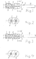
- a contact carrier which has two parallel and spaced-apart through holes 2 and 3.
- contact elements 4 and 5 are arranged undisturbed.
- the contact elements 4 and 5 can be used as plug pins or as Bushings be executed.
- an electrical line 10 is connected to the contact elements 4 and 5 .
- insulating materials for the wires for example, polyvinyl chloride or crosslinked polyethylene can be used.
- the line 10 has in the illustrated embodiment, an insulating material, such as polyvinyl chloride or polyurethane, existing jacket 11, which surrounds the two wires 8 and 9 as a common jacket.
- an in Fig. 6 illustrated coupling part K is for example as follows:
- the wires 8 and 9 are freed from the jacket 11 at the end of the line 10 to a predeterminable length.
- the thus exposed cores 8 and 9 are stripped at their ends, so that their conductors 6 and 7 are available for contacting purposes.
- the contact elements 4 and 5 are then electrically connected to the conductors 6 and 7, for example by crimping. They are then inserted together with the wires 8 and 9 in the through holes 2 and 3 to a locking position in which the contact elements 4 and 5 are fixed immovably.
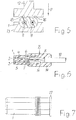
- a tool is applied to the contact carrier 1 at least at one point over the wires 8 and 9 from the outside, which is, for example and advantageously, an ultrasonic welding system which has a sonotrode 12 and an anvil 13.
- the contact carrier 1 is in carrying out the process on the anvil 13.
- the sonotrode 12 is then brought by movement in the direction of arrow P until it rests against the contact carrier 1 and pressed against the same.
- the material of the contact carrier 1 is heated by the vibrations of the sonotrode 12 lying in the ultrasonic range so far that it flows into the through holes 2 and 3 and completely closes them.
- the wires 8 and 9 are then embedded all around in the tight-fitting material of the contact carrier 1 and the through holes 2 and 3 are closed.
- a protective body 14 is sprayed around the end of the contact carrier 1, which extends over the line 10.
- the finished coupling part K goes out Fig. 6 out.
- the contact surface of the sonotrode 12 of the ultrasonic welding system can be adapted to the shape and structure of the line 10, which has two wires 8 and 9 in the illustrated embodiment.
- the sonotrode 12 may advantageously have in its central region projections 15 and 16, which lie in a region of the contact carrier 1, which is located above the two wires 8 and 9.
- the contact carrier 1 is deformed in accordance with the preceding embodiments in at least one of the wires 8 and 9 detected area, namely from the material of the contact carrier 1 itself, without additional material costs. It is also possible to close the through-holes 2 and 3 of the contact carrier 1 directly at its line-side end. For this purpose, for example, at this end of the contact carrier 1, a radially outwardly projecting bead 17 may be attached, as it is in Fig. 7 is shown. The bead 17 is advantageously dimensioned so that its material causes a complete sealing of the through holes 2 and 3 on the end face of the contact carrier 1.
- a hot stamping system could also be used. It has, for example, a heatable stamp, which is pressed against the contact carrier 1 at least at one point from the outside.
Claims (4)
- Procédé d'étanchéification imperméable d'un élément de connexion électrique qui présente un support de contact (1) composé de matière plastique, lequel a au moins deux trous de passage (2, 3) espacés et parallèles entre eux, dans lequel des éléments de contact (4, 5) électriques, auxquels sont connectés des fils (8, 9) d'une ligne (10) électrique réalisés respectivement en tant que conducteurs électriques entourés d'une isolation, sont introduits dans les trous de passage (2, 3) de telle sorte que, dans chaque trou de passage (2, 3), sont disposés un élément de contact (4, 5) et le fil (8, 9) connecté à celui-ci, dans lequel les fils (8, 9) sont, à une extrémité du support de contact (1), extraits des trous de passage (2, 3) et avec lequel, autour de l'extrémité côté ligne de l'élément de connexion, il est formé un corps de protection (14) produit par moulage par injection qui s'étend jusqu'au-dessus de la ligne (10),
caractérisé en ce que- après l'introduction dans les trous de passage (2, 3) d'éléments de contact (4, 5) et de fils (8, 9) connectés, le support de contact (1) est d'abord déformé à au moins un endroit dans la zone des fils (8, 9) disposés dans les trous de passage (2, 3) par l'application de chaleur et de pression au moyen d'un outil apposé à l'extérieur sur le support de contact (1) de telle sorte que son matériau se pose tout autour contre l'isolation des fils (8, 9), et- en ce que le corps de protection (14) est ensuite injecté autour des extrémités du support de contact (1) et de la ligne (10) . - Procédé selon la revendication 1, caractérisé en ce que, à l'extrémité du support de contact (1), il est mis en place un bourrelet (17) dépassant radialement vers l'extérieur, qui est dimensionné de telle sorte que son matériau réalise, par l'application de chaleur et de pression au moyen de l'outil, une étanchéité complète des trous de passage (2, 3) sur la surface frontale du support de contact (1).
- Procédé selon la revendication 1 ou 2, caractérisé en ce qu'une installation de soudage par ultrasons est utilisée comme outil.
- Procédé selon la revendication 1 ou 2, caractérisé en ce qu'une installation de matage à chaud est utilisée comme outil.
Priority Applications (1)
| Application Number | Priority Date | Filing Date | Title |
|---|---|---|---|
| EP16305150.1A EP3206268B1 (fr) | 2016-02-09 | 2016-02-09 | Procede d'etancheification impermeable d'un element de connection electrique |
Applications Claiming Priority (1)
| Application Number | Priority Date | Filing Date | Title |
|---|---|---|---|
| EP16305150.1A EP3206268B1 (fr) | 2016-02-09 | 2016-02-09 | Procede d'etancheification impermeable d'un element de connection electrique |
Publications (2)
| Publication Number | Publication Date |
|---|---|
| EP3206268A1 EP3206268A1 (fr) | 2017-08-16 |
| EP3206268B1 true EP3206268B1 (fr) | 2018-08-15 |
Family
ID=55361446
Family Applications (1)
| Application Number | Title | Priority Date | Filing Date |
|---|---|---|---|
| EP16305150.1A Active EP3206268B1 (fr) | 2016-02-09 | 2016-02-09 | Procede d'etancheification impermeable d'un element de connection electrique |
Country Status (1)
| Country | Link |
|---|---|
| EP (1) | EP3206268B1 (fr) |
Family Cites Families (5)
| Publication number | Priority date | Publication date | Assignee | Title |
|---|---|---|---|---|
| DE3417811C1 (de) * | 1984-05-14 | 1985-10-17 | kabelmetal electro GmbH, 3000 Hannover | Verfahren zum Anbringen eines Kupplungsteils am Ende einer elektrischen Leitung |
| DE9410092U1 (de) * | 1994-06-22 | 1994-08-11 | Ke Autoelectric Gmbh | Kupplungsteil einer elektrischen Leitungskupplung |
| US5590463A (en) * | 1995-07-18 | 1997-01-07 | Elco Corporation | Circuit board connectors |
| US5681188A (en) * | 1996-08-13 | 1997-10-28 | Cheng Uei Plastic Component Corp. | Electrical connector |
| EP2099099B1 (fr) | 2008-03-06 | 2010-06-09 | Nexans | Elément de connexion électrique doté d'un câble électrique connecté |
-
2016
- 2016-02-09 EP EP16305150.1A patent/EP3206268B1/fr active Active
Non-Patent Citations (1)
| Title |
|---|
| None * |
Also Published As
| Publication number | Publication date |
|---|---|
| EP3206268A1 (fr) | 2017-08-16 |
Similar Documents
| Publication | Publication Date | Title |
|---|---|---|
| DE112008003276B4 (de) | Verfahren zum Ausbilden eines wasserdichten Verbindungsabscchnitts und Kabelbaum, welcher mit einem wasserdichten, durch das Verfahren ausgebildeten Verbindungsabschnitt versehen ist | |
| EP2027629B1 (fr) | Connecteur enfichable blindé et son procédé de réalisation | |
| DE4214508C2 (de) | Anordnung zur Masseanbindung an eine innere Blitzschutzanlage | |
| DE112008003375T5 (de) | Wasserabdichtverfahren für einen Draht und Draht, welcher ein wasserdichtes Teil aufweist, welches durch das Wasserabdichtverfahren gebildet ist | |
| DE102012100142B4 (de) | Verfahren zur Herstellung eines Kabelstrangs | |
| DE102018005264B4 (de) | Draht mit Anschluss, Verbindervorrichtung und Herstellungsverfahren | |
| DE112012003786T5 (de) | Verbindungsklemme | |
| DE112014001079T5 (de) | Kabelstrang | |
| EP3878056A1 (fr) | Elément de contact pour effectuer la mise en contact électrique d'un conducteur électrique sur une partie de raccordement d'une installation électrique et procédé pour le fabriquer | |
| EP3878054A1 (fr) | Cosse de câble, élément de contact et son procédé fabrication correspondant | |
| EP3340392B1 (fr) | Système de branchement de conduites électriques | |
| EP3477777B1 (fr) | Ligne électrique pourvue d'un terminal de blindage | |
| EP2192655B1 (fr) | Connecteur étanche pour câbles à haute tension dans l'industrie automobile | |
| EP2950399B1 (fr) | Etanchéification de l'emplacement de liaison entre deux conducteurs | |
| EP2245705B1 (fr) | Élément connecteur à fiche, à effet d'étanchéité dans la région de raccordement du câble | |
| EP2099099B1 (fr) | Elément de connexion électrique doté d'un câble électrique connecté | |
| EP2731203B1 (fr) | Procédé de recouvrement imperméable d'un emplacement de liaison entre un conducteur électrique et un élément de contact | |
| EP3503307B1 (fr) | Élément d'accouplement électrique | |
| DE102008031085A1 (de) | Kupplungsteil für eine elektrische Leitung | |
| EP3206268B1 (fr) | Procede d'etancheification impermeable d'un element de connection electrique | |
| DE102007034817B4 (de) | Gedichtetes Kontaktgehäuse für eine elektrische Steckverbindung in einem Fahrzeug | |
| EP3619781B1 (fr) | Composant électrique et procédé pour sa fabrication | |
| EP2706620B1 (fr) | Procédé destiné à étanchéifier un élément d'embrayage électrique et élément d'embrayage fabriqué avec ce procédé | |
| DE19525801C2 (de) | Vorrichtung zum elektrisch leitenden Verbinden von zwei elektrischen Leitungen | |
| WO2000069032A1 (fr) | Procede de protection de torons de cables |
Legal Events
| Date | Code | Title | Description |
|---|---|---|---|
| PUAI | Public reference made under article 153(3) epc to a published international application that has entered the european phase |
Free format text: ORIGINAL CODE: 0009012 |
|
| STAA | Information on the status of an ep patent application or granted ep patent |
Free format text: STATUS: REQUEST FOR EXAMINATION WAS MADE |
|
| 17P | Request for examination filed |
Effective date: 20160909 |
|
| AK | Designated contracting states |
Kind code of ref document: A1 Designated state(s): AL AT BE BG CH CY CZ DE DK EE ES FI FR GB GR HR HU IE IS IT LI LT LU LV MC MK MT NL NO PL PT RO RS SE SI SK SM TR |
|
| AX | Request for extension of the european patent |
Extension state: BA ME |
|
| GRAP | Despatch of communication of intention to grant a patent |
Free format text: ORIGINAL CODE: EPIDOSNIGR1 |
|
| STAA | Information on the status of an ep patent application or granted ep patent |
Free format text: STATUS: GRANT OF PATENT IS INTENDED |
|
| INTG | Intention to grant announced |
Effective date: 20180314 |
|
| GRAS | Grant fee paid |
Free format text: ORIGINAL CODE: EPIDOSNIGR3 |
|
| GRAA | (expected) grant |
Free format text: ORIGINAL CODE: 0009210 |
|
| STAA | Information on the status of an ep patent application or granted ep patent |
Free format text: STATUS: THE PATENT HAS BEEN GRANTED |
|
| AK | Designated contracting states |
Kind code of ref document: B1 Designated state(s): AL AT BE BG CH CY CZ DE DK EE ES FI FR GB GR HR HU IE IS IT LI LT LU LV MC MK MT NL NO PL PT RO RS SE SI SK SM TR |
|
| REG | Reference to a national code |
Ref country code: CH Ref legal event code: EP Ref country code: GB Ref legal event code: FG4D Free format text: NOT ENGLISH Ref country code: AT Ref legal event code: REF Ref document number: 1030865 Country of ref document: AT Kind code of ref document: T Effective date: 20180815 |
|
| REG | Reference to a national code |
Ref country code: IE Ref legal event code: FG4D Free format text: LANGUAGE OF EP DOCUMENT: GERMAN |
|
| REG | Reference to a national code |
Ref country code: DE Ref legal event code: R096 Ref document number: 502016001698 Country of ref document: DE |
|
| REG | Reference to a national code |
Ref country code: SE Ref legal event code: TRGR |
|
| REG | Reference to a national code |
Ref country code: NL Ref legal event code: MP Effective date: 20180815 |
|
| REG | Reference to a national code |
Ref country code: LT Ref legal event code: MG4D |
|
| PG25 | Lapsed in a contracting state [announced via postgrant information from national office to epo] |
Ref country code: LT Free format text: LAPSE BECAUSE OF FAILURE TO SUBMIT A TRANSLATION OF THE DESCRIPTION OR TO PAY THE FEE WITHIN THE PRESCRIBED TIME-LIMIT Effective date: 20180815 Ref country code: RS Free format text: LAPSE BECAUSE OF FAILURE TO SUBMIT A TRANSLATION OF THE DESCRIPTION OR TO PAY THE FEE WITHIN THE PRESCRIBED TIME-LIMIT Effective date: 20180815 Ref country code: IS Free format text: LAPSE BECAUSE OF FAILURE TO SUBMIT A TRANSLATION OF THE DESCRIPTION OR TO PAY THE FEE WITHIN THE PRESCRIBED TIME-LIMIT Effective date: 20181215 Ref country code: BG Free format text: LAPSE BECAUSE OF FAILURE TO SUBMIT A TRANSLATION OF THE DESCRIPTION OR TO PAY THE FEE WITHIN THE PRESCRIBED TIME-LIMIT Effective date: 20181115 Ref country code: NL Free format text: LAPSE BECAUSE OF FAILURE TO SUBMIT A TRANSLATION OF THE DESCRIPTION OR TO PAY THE FEE WITHIN THE PRESCRIBED TIME-LIMIT Effective date: 20180815 Ref country code: NO Free format text: LAPSE BECAUSE OF FAILURE TO SUBMIT A TRANSLATION OF THE DESCRIPTION OR TO PAY THE FEE WITHIN THE PRESCRIBED TIME-LIMIT Effective date: 20181115 Ref country code: GR Free format text: LAPSE BECAUSE OF FAILURE TO SUBMIT A TRANSLATION OF THE DESCRIPTION OR TO PAY THE FEE WITHIN THE PRESCRIBED TIME-LIMIT Effective date: 20181116 Ref country code: FI Free format text: LAPSE BECAUSE OF FAILURE TO SUBMIT A TRANSLATION OF THE DESCRIPTION OR TO PAY THE FEE WITHIN THE PRESCRIBED TIME-LIMIT Effective date: 20180815 |
|
| PG25 | Lapsed in a contracting state [announced via postgrant information from national office to epo] |
Ref country code: AL Free format text: LAPSE BECAUSE OF FAILURE TO SUBMIT A TRANSLATION OF THE DESCRIPTION OR TO PAY THE FEE WITHIN THE PRESCRIBED TIME-LIMIT Effective date: 20180815 Ref country code: LV Free format text: LAPSE BECAUSE OF FAILURE TO SUBMIT A TRANSLATION OF THE DESCRIPTION OR TO PAY THE FEE WITHIN THE PRESCRIBED TIME-LIMIT Effective date: 20180815 Ref country code: HR Free format text: LAPSE BECAUSE OF FAILURE TO SUBMIT A TRANSLATION OF THE DESCRIPTION OR TO PAY THE FEE WITHIN THE PRESCRIBED TIME-LIMIT Effective date: 20180815 |
|
| PG25 | Lapsed in a contracting state [announced via postgrant information from national office to epo] |
Ref country code: CZ Free format text: LAPSE BECAUSE OF FAILURE TO SUBMIT A TRANSLATION OF THE DESCRIPTION OR TO PAY THE FEE WITHIN THE PRESCRIBED TIME-LIMIT Effective date: 20180815 Ref country code: EE Free format text: LAPSE BECAUSE OF FAILURE TO SUBMIT A TRANSLATION OF THE DESCRIPTION OR TO PAY THE FEE WITHIN THE PRESCRIBED TIME-LIMIT Effective date: 20180815 Ref country code: PL Free format text: LAPSE BECAUSE OF FAILURE TO SUBMIT A TRANSLATION OF THE DESCRIPTION OR TO PAY THE FEE WITHIN THE PRESCRIBED TIME-LIMIT Effective date: 20180815 Ref country code: ES Free format text: LAPSE BECAUSE OF FAILURE TO SUBMIT A TRANSLATION OF THE DESCRIPTION OR TO PAY THE FEE WITHIN THE PRESCRIBED TIME-LIMIT Effective date: 20180815 Ref country code: RO Free format text: LAPSE BECAUSE OF FAILURE TO SUBMIT A TRANSLATION OF THE DESCRIPTION OR TO PAY THE FEE WITHIN THE PRESCRIBED TIME-LIMIT Effective date: 20180815 |
|
| REG | Reference to a national code |
Ref country code: DE Ref legal event code: R097 Ref document number: 502016001698 Country of ref document: DE |
|
| PG25 | Lapsed in a contracting state [announced via postgrant information from national office to epo] |
Ref country code: SM Free format text: LAPSE BECAUSE OF FAILURE TO SUBMIT A TRANSLATION OF THE DESCRIPTION OR TO PAY THE FEE WITHIN THE PRESCRIBED TIME-LIMIT Effective date: 20180815 Ref country code: DK Free format text: LAPSE BECAUSE OF FAILURE TO SUBMIT A TRANSLATION OF THE DESCRIPTION OR TO PAY THE FEE WITHIN THE PRESCRIBED TIME-LIMIT Effective date: 20180815 Ref country code: SK Free format text: LAPSE BECAUSE OF FAILURE TO SUBMIT A TRANSLATION OF THE DESCRIPTION OR TO PAY THE FEE WITHIN THE PRESCRIBED TIME-LIMIT Effective date: 20180815 |
|
| PLBE | No opposition filed within time limit |
Free format text: ORIGINAL CODE: 0009261 |
|
| STAA | Information on the status of an ep patent application or granted ep patent |
Free format text: STATUS: NO OPPOSITION FILED WITHIN TIME LIMIT |
|
| 26N | No opposition filed |
Effective date: 20190516 |
|
| PG25 | Lapsed in a contracting state [announced via postgrant information from national office to epo] |
Ref country code: SI Free format text: LAPSE BECAUSE OF FAILURE TO SUBMIT A TRANSLATION OF THE DESCRIPTION OR TO PAY THE FEE WITHIN THE PRESCRIBED TIME-LIMIT Effective date: 20180815 |
|
| REG | Reference to a national code |
Ref country code: CH Ref legal event code: PL |
|
| PG25 | Lapsed in a contracting state [announced via postgrant information from national office to epo] |
Ref country code: LU Free format text: LAPSE BECAUSE OF NON-PAYMENT OF DUE FEES Effective date: 20190209 Ref country code: MC Free format text: LAPSE BECAUSE OF FAILURE TO SUBMIT A TRANSLATION OF THE DESCRIPTION OR TO PAY THE FEE WITHIN THE PRESCRIBED TIME-LIMIT Effective date: 20180815 |
|
| REG | Reference to a national code |
Ref country code: BE Ref legal event code: MM Effective date: 20190228 |
|
| REG | Reference to a national code |
Ref country code: IE Ref legal event code: MM4A |
|
| PG25 | Lapsed in a contracting state [announced via postgrant information from national office to epo] |
Ref country code: LI Free format text: LAPSE BECAUSE OF NON-PAYMENT OF DUE FEES Effective date: 20190228 Ref country code: CH Free format text: LAPSE BECAUSE OF NON-PAYMENT OF DUE FEES Effective date: 20190228 |
|
| PG25 | Lapsed in a contracting state [announced via postgrant information from national office to epo] |
Ref country code: IE Free format text: LAPSE BECAUSE OF NON-PAYMENT OF DUE FEES Effective date: 20190209 |
|
| PG25 | Lapsed in a contracting state [announced via postgrant information from national office to epo] |
Ref country code: BE Free format text: LAPSE BECAUSE OF NON-PAYMENT OF DUE FEES Effective date: 20190228 |
|
| PG25 | Lapsed in a contracting state [announced via postgrant information from national office to epo] |
Ref country code: TR Free format text: LAPSE BECAUSE OF FAILURE TO SUBMIT A TRANSLATION OF THE DESCRIPTION OR TO PAY THE FEE WITHIN THE PRESCRIBED TIME-LIMIT Effective date: 20180815 |
|
| PG25 | Lapsed in a contracting state [announced via postgrant information from national office to epo] |
Ref country code: PT Free format text: LAPSE BECAUSE OF FAILURE TO SUBMIT A TRANSLATION OF THE DESCRIPTION OR TO PAY THE FEE WITHIN THE PRESCRIBED TIME-LIMIT Effective date: 20181215 Ref country code: MT Free format text: LAPSE BECAUSE OF FAILURE TO SUBMIT A TRANSLATION OF THE DESCRIPTION OR TO PAY THE FEE WITHIN THE PRESCRIBED TIME-LIMIT Effective date: 20180815 |
|
| GBPC | Gb: european patent ceased through non-payment of renewal fee |
Effective date: 20200209 |
|
| PG25 | Lapsed in a contracting state [announced via postgrant information from national office to epo] |
Ref country code: GB Free format text: LAPSE BECAUSE OF NON-PAYMENT OF DUE FEES Effective date: 20200209 |
|
| PG25 | Lapsed in a contracting state [announced via postgrant information from national office to epo] |
Ref country code: CY Free format text: LAPSE BECAUSE OF FAILURE TO SUBMIT A TRANSLATION OF THE DESCRIPTION OR TO PAY THE FEE WITHIN THE PRESCRIBED TIME-LIMIT Effective date: 20180815 |
|
| PG25 | Lapsed in a contracting state [announced via postgrant information from national office to epo] |
Ref country code: HU Free format text: LAPSE BECAUSE OF FAILURE TO SUBMIT A TRANSLATION OF THE DESCRIPTION OR TO PAY THE FEE WITHIN THE PRESCRIBED TIME-LIMIT; INVALID AB INITIO Effective date: 20160209 |
|
| REG | Reference to a national code |
Ref country code: AT Ref legal event code: MM01 Ref document number: 1030865 Country of ref document: AT Kind code of ref document: T Effective date: 20210209 |
|
| PG25 | Lapsed in a contracting state [announced via postgrant information from national office to epo] |
Ref country code: AT Free format text: LAPSE BECAUSE OF NON-PAYMENT OF DUE FEES Effective date: 20210209 |
|
| PG25 | Lapsed in a contracting state [announced via postgrant information from national office to epo] |
Ref country code: MK Free format text: LAPSE BECAUSE OF FAILURE TO SUBMIT A TRANSLATION OF THE DESCRIPTION OR TO PAY THE FEE WITHIN THE PRESCRIBED TIME-LIMIT Effective date: 20180815 |
|
| PGFP | Annual fee paid to national office [announced via postgrant information from national office to epo] |
Ref country code: FR Payment date: 20230221 Year of fee payment: 8 |
|
| PGFP | Annual fee paid to national office [announced via postgrant information from national office to epo] |
Ref country code: SE Payment date: 20230216 Year of fee payment: 8 Ref country code: IT Payment date: 20230223 Year of fee payment: 8 |
|
| PGFP | Annual fee paid to national office [announced via postgrant information from national office to epo] |
Ref country code: DE Payment date: 20240219 Year of fee payment: 9 |