EP3205954B1 - Dispositif de circuit de réfrigération - Google Patents
Dispositif de circuit de réfrigération Download PDFInfo
- Publication number
- EP3205954B1 EP3205954B1 EP17155400.9A EP17155400A EP3205954B1 EP 3205954 B1 EP3205954 B1 EP 3205954B1 EP 17155400 A EP17155400 A EP 17155400A EP 3205954 B1 EP3205954 B1 EP 3205954B1
- Authority
- EP
- European Patent Office
- Prior art keywords
- water
- heat exchanger
- refrigerant
- unit
- outdoor
- Prior art date
- Legal status (The legal status is an assumption and is not a legal conclusion. Google has not performed a legal analysis and makes no representation as to the accuracy of the status listed.)
- Active
Links
- 238000005057 refrigeration Methods 0.000 title claims description 30
- XLYOFNOQVPJJNP-UHFFFAOYSA-N water Substances O XLYOFNOQVPJJNP-UHFFFAOYSA-N 0.000 claims description 299
- 239000003507 refrigerant Substances 0.000 claims description 151
- 238000007710 freezing Methods 0.000 claims description 59
- 230000008014 freezing Effects 0.000 claims description 41
- 230000007423 decrease Effects 0.000 claims description 5
- 230000003247 decreasing effect Effects 0.000 claims description 5
- 238000001514 detection method Methods 0.000 claims description 3
- 239000007788 liquid Substances 0.000 description 42
- 238000001816 cooling Methods 0.000 description 17
- 238000004781 supercooling Methods 0.000 description 12
- 230000033228 biological regulation Effects 0.000 description 10
- 238000010438 heat treatment Methods 0.000 description 10
- 238000010586 diagram Methods 0.000 description 6
- 239000000314 lubricant Substances 0.000 description 4
- 230000005514 two-phase flow Effects 0.000 description 4
- 239000012809 cooling fluid Substances 0.000 description 3
- 238000000034 method Methods 0.000 description 3
- 230000004048 modification Effects 0.000 description 3
- 238000012986 modification Methods 0.000 description 3
- 238000011112 process operation Methods 0.000 description 3
- 238000007664 blowing Methods 0.000 description 2
- 238000004378 air conditioning Methods 0.000 description 1
- 239000012267 brine Substances 0.000 description 1
- 238000010276 construction Methods 0.000 description 1
- 239000000498 cooling water Substances 0.000 description 1
- 230000000694 effects Effects 0.000 description 1
- 238000005516 engineering process Methods 0.000 description 1
- 230000008020 evaporation Effects 0.000 description 1
- 238000001704 evaporation Methods 0.000 description 1
- HPALAKNZSZLMCH-UHFFFAOYSA-M sodium;chloride;hydrate Chemical compound O.[Na+].[Cl-] HPALAKNZSZLMCH-UHFFFAOYSA-M 0.000 description 1
- 239000000243 solution Substances 0.000 description 1
- 238000006467 substitution reaction Methods 0.000 description 1
Images


Classifications
-
- F—MECHANICAL ENGINEERING; LIGHTING; HEATING; WEAPONS; BLASTING
- F25—REFRIGERATION OR COOLING; COMBINED HEATING AND REFRIGERATION SYSTEMS; HEAT PUMP SYSTEMS; MANUFACTURE OR STORAGE OF ICE; LIQUEFACTION SOLIDIFICATION OF GASES
- F25B—REFRIGERATION MACHINES, PLANTS OR SYSTEMS; COMBINED HEATING AND REFRIGERATION SYSTEMS; HEAT PUMP SYSTEMS
- F25B13/00—Compression machines, plants or systems, with reversible cycle
-
- F—MECHANICAL ENGINEERING; LIGHTING; HEATING; WEAPONS; BLASTING
- F25—REFRIGERATION OR COOLING; COMBINED HEATING AND REFRIGERATION SYSTEMS; HEAT PUMP SYSTEMS; MANUFACTURE OR STORAGE OF ICE; LIQUEFACTION SOLIDIFICATION OF GASES
- F25B—REFRIGERATION MACHINES, PLANTS OR SYSTEMS; COMBINED HEATING AND REFRIGERATION SYSTEMS; HEAT PUMP SYSTEMS
- F25B47/00—Arrangements for preventing or removing deposits or corrosion, not provided for in another subclass
- F25B47/006—Arrangements for preventing or removing deposits or corrosion, not provided for in another subclass for preventing frost
-
- F—MECHANICAL ENGINEERING; LIGHTING; HEATING; WEAPONS; BLASTING
- F25—REFRIGERATION OR COOLING; COMBINED HEATING AND REFRIGERATION SYSTEMS; HEAT PUMP SYSTEMS; MANUFACTURE OR STORAGE OF ICE; LIQUEFACTION SOLIDIFICATION OF GASES
- F25B—REFRIGERATION MACHINES, PLANTS OR SYSTEMS; COMBINED HEATING AND REFRIGERATION SYSTEMS; HEAT PUMP SYSTEMS
- F25B47/00—Arrangements for preventing or removing deposits or corrosion, not provided for in another subclass
- F25B47/02—Defrosting cycles
-
- F—MECHANICAL ENGINEERING; LIGHTING; HEATING; WEAPONS; BLASTING
- F25—REFRIGERATION OR COOLING; COMBINED HEATING AND REFRIGERATION SYSTEMS; HEAT PUMP SYSTEMS; MANUFACTURE OR STORAGE OF ICE; LIQUEFACTION SOLIDIFICATION OF GASES
- F25B—REFRIGERATION MACHINES, PLANTS OR SYSTEMS; COMBINED HEATING AND REFRIGERATION SYSTEMS; HEAT PUMP SYSTEMS
- F25B49/00—Arrangement or mounting of control or safety devices
- F25B49/02—Arrangement or mounting of control or safety devices for compression type machines, plants or systems
-
- F—MECHANICAL ENGINEERING; LIGHTING; HEATING; WEAPONS; BLASTING
- F25—REFRIGERATION OR COOLING; COMBINED HEATING AND REFRIGERATION SYSTEMS; HEAT PUMP SYSTEMS; MANUFACTURE OR STORAGE OF ICE; LIQUEFACTION SOLIDIFICATION OF GASES
- F25B—REFRIGERATION MACHINES, PLANTS OR SYSTEMS; COMBINED HEATING AND REFRIGERATION SYSTEMS; HEAT PUMP SYSTEMS
- F25B2313/00—Compression machines, plants or systems with reversible cycle not otherwise provided for
- F25B2313/003—Indoor unit with water as a heat sink or heat source
-
- F—MECHANICAL ENGINEERING; LIGHTING; HEATING; WEAPONS; BLASTING
- F25—REFRIGERATION OR COOLING; COMBINED HEATING AND REFRIGERATION SYSTEMS; HEAT PUMP SYSTEMS; MANUFACTURE OR STORAGE OF ICE; LIQUEFACTION SOLIDIFICATION OF GASES
- F25B—REFRIGERATION MACHINES, PLANTS OR SYSTEMS; COMBINED HEATING AND REFRIGERATION SYSTEMS; HEAT PUMP SYSTEMS
- F25B2313/00—Compression machines, plants or systems with reversible cycle not otherwise provided for
- F25B2313/023—Compression machines, plants or systems with reversible cycle not otherwise provided for using multiple indoor units
- F25B2313/0232—Compression machines, plants or systems with reversible cycle not otherwise provided for using multiple indoor units with bypasses
- F25B2313/02322—Compression machines, plants or systems with reversible cycle not otherwise provided for using multiple indoor units with bypasses during defrosting
-
- F—MECHANICAL ENGINEERING; LIGHTING; HEATING; WEAPONS; BLASTING
- F25—REFRIGERATION OR COOLING; COMBINED HEATING AND REFRIGERATION SYSTEMS; HEAT PUMP SYSTEMS; MANUFACTURE OR STORAGE OF ICE; LIQUEFACTION SOLIDIFICATION OF GASES
- F25B—REFRIGERATION MACHINES, PLANTS OR SYSTEMS; COMBINED HEATING AND REFRIGERATION SYSTEMS; HEAT PUMP SYSTEMS
- F25B2313/00—Compression machines, plants or systems with reversible cycle not otherwise provided for
- F25B2313/023—Compression machines, plants or systems with reversible cycle not otherwise provided for using multiple indoor units
- F25B2313/0233—Compression machines, plants or systems with reversible cycle not otherwise provided for using multiple indoor units in parallel arrangements
-
- F—MECHANICAL ENGINEERING; LIGHTING; HEATING; WEAPONS; BLASTING
- F25—REFRIGERATION OR COOLING; COMBINED HEATING AND REFRIGERATION SYSTEMS; HEAT PUMP SYSTEMS; MANUFACTURE OR STORAGE OF ICE; LIQUEFACTION SOLIDIFICATION OF GASES
- F25B—REFRIGERATION MACHINES, PLANTS OR SYSTEMS; COMBINED HEATING AND REFRIGERATION SYSTEMS; HEAT PUMP SYSTEMS
- F25B2700/00—Sensing or detecting of parameters; Sensors therefor
- F25B2700/19—Pressures
- F25B2700/193—Pressures of the compressor
- F25B2700/1933—Suction pressures
Definitions
- the present invention relates to a refrigeration cycle device including a water heat exchanger which exchanges heat between a refrigerant and water.
- a cooling device which includes a compressor compressing a refrigerant, a condenser, a depressurization unit, and an evaporator.
- the cooling device cools a target cooling fluid by circulating a refrigerant in these components and exchanging heat between the refrigerant and the target cooling fluid through the evaporator.
- a technology of preventing the target cooling fluid from being frozen in the evaporator for example, see Patent Literature 1).
- Patent Literature 1 JP 2009-243828 A
- a refrigeration cycle device including an outdoor unit which includes a compressor compressing a refrigerant and an outdoor heat exchanger and a water temperature control unit which includes a water heat exchanger exchanging heat between water and a refrigerant supplied from the outdoor unit. Since such a refrigeration cycle device is provided in an architecture such as a building, the water temperature control unit is provided at a position separated from the outdoor unit through a unit connection pipe.
- the document EP2781854 A discloses a refrigeration cycle device according to the preamble of claim 1. In this configuration, there has been a desire for highly accurately determining whether water in the water heat exchanger is going to be frozen.
- the invention is made in view of the above-described circumstances and an object of the invention is to provide a refrigeration cycle device capable of highly accurately determining whether water in a water heat exchanger is going to be frozen.
- the present invention includes an outdoor unit which includes a compressor compressing a refrigerant and an outdoor heat exchanger exchanging heat between a refrigerant and external air and a water temperature control unit which includes a water heat exchanger connected to the outdoor unit through a unit connection pipe, the water heat exchanger exchanging heat between water and the refrigerant supplied from the outdoor unit.
- the refrigeration cycle device comprises a low pressure detection unit which is configured to detect a low pressure of the refrigerant at a suction side of the compressor, and a freezing determination unit which is configured to determine that the water flowing through the water heat exchanger is going to be frozen when the low pressure is lower than a predetermined low-pressure protection value during an operation in which the water heat exchanger serves as an evaporator, the low-pressure protection value set in consideration of pressure loss generated by flow of the refrigerant through the unit connection pipe.
- the freezing determination unit determines whether water flowing through the water heat exchanger is going to be frozen by comparing a low pressure with a predetermined low-pressure protection value set in consideration of pressure loss generated when a refrigerant flows through the unit connection pipe. Therefore, it is possible to highly accurately determine whether water in the water heat exchanger is going to be frozen even in a configuration in which the water temperature control unit is disposed at a position separated from the outdoor unit. Further, even when the refrigerant circulation amount is small and the refrigerant temperature sensor cannot highly accurately detect the refrigerant temperature so that the possibility of the freezing of water cannot be detected, it is possible to detect a possibility that water is going to be frozen by a microscopic structure inside the water heat exchanger.
- a low-pressure protection value correction unit which is configured to correct the low-pressure protection value to a high value when a temperature of the refrigerant flowing through the water heat exchanger decreases to an anti-frost temperature higher than a freezing reference temperature of the water, and is configured to correct the low-pressure protection value to a low value when a temperature of the refrigerant increases to an anti-frost cancellation temperature higher than the anti-frost temperature.
- an indoor unit which is connected to the outdoor unit in parallel to the water temperature control unit and includes an indoor heat exchanger exchanging heat between the refrigerant and indoor air
- the water temperature control unit includes a control valve which is provided at a refrigerant inlet side of the water heat exchanger, a bypass pipe which is configured to bypass the control valve and the water heat exchanger, and a bypass valve which is provided in the bypass pipe
- the refrigeration cycle device further comprises an anti-freezing control unit which prevents water from being frozen by closing the control valve and opening the bypass valve when the freezing determination unit determines that the water flowing through the water heat exchanger is going to be frozen.
- the anti-freezing control unit closes the control valve and opens the bypass valve so as to prevent the refrigerant from flowing into the water heat exchanger. Further, since the high-temperature refrigerant bypasses the water heat exchanger, it is possible to expect a case where an operation point changes in a direction in which the freezing is prevented in accordance with an increase in low pressure of the refrigeration cycle device. For this reason, it is possible to prevent the water flowing through the water heat exchanger from being frozen without disturbing the operations of the outdoor unit and the indoor unit.
- the water temperature control unit may include a water circulation path which is configured to supply the water to the water heat exchanger in a circulation manner, and wherein the refrigeration cycle device further comprises an anti-freezing control unit which is configured to prevent water from being frozen by decreasing an ability of the compressor and supplying the water to the water heat exchanger in a circulation manner when the freezing determination unit determines that the water flowing through the water heat exchanger is going to be frozen.
- the anti-freezing control unit decreases the ability of the compressor when it is determined that the water flowing through the water heat exchanger is going to be frozen, it is possible to suppress an amount of the refrigerant flowing into the water heat exchanger.
- the anti-freezing control unit supplies water to the water heat exchanger through the water circulation path in a circulation manner, the refrigerant flowing into the water heat exchanger exchanges heat with the circulated water. Accordingly, it is possible to prevent the water flowing through the water heat exchanger from being frozen without disturbing the operation of the outdoor unit.
- the operation in which the water heat exchanger serves as the evaporator may include a defrost operation of preventing a frost of the outdoor heat exchanger.
- a defrost operation of preventing a frost of the outdoor heat exchanger.
- the freezing determination unit determines whether the water flowing through the water heat exchanger is going to be frozen by comparing the low pressure with the predetermined low-pressure protection value set in consideration of the pressure loss generated when the refrigerant flows through the unit connection pipe, it is possible to highly accurately determine whether the water in the water heat exchanger is going to be frozen even in a configuration in which the water temperature control unit is disposed at a position separated from the outdoor unit.
- components of the embodiment include a component which can be easily replaced by the person skilled in the art or a component which has the substantially same configuration. Furthermore, an appropriate combination of the components to be described below can be used.
- FIG. 1 is a circuit configuration diagram of an air conditioner according to the embodiment.
- An air conditioner (refrigeration cycle device) 1 is a multi-type air conditioner including one outdoor unit 2, a plurality of (two in FIG. 1 ) indoor units 3A and 3B, and one water temperature control unit 40.
- the indoor units 3A and 3B and the water temperature control unit 40 are connected in parallel to a unit connection pipe 6 lead from the outdoor unit 2.
- the unit connection pipe 6 includes a liquid pipe 5 through which a liquid refrigerant flows and a gas pipe 4 through which a refrigerant gas having been gasified from the liquid refrigerant flows.
- the outdoor unit 2 includes an compressor 10 which compresses a refrigerant driven by inverter, an oil separator 11 which separates lubricant from a refrigerant gas, a four-way valve 12 which switches a refrigerant circulation direction, an outdoor heat exchanger 13 which exchanges heat between a refrigerant and external air, an outdoor expansion valve 15 which is used for an air heating operation to depressurize and expand a refrigerant, a receiver 16 which stores a liquid refrigerant, a supercooling heat exchanger 17 which supercools a liquid refrigerant, a supercooling expansion valve 18 which controls an amount of a refrigerant distributed to the supercooling heat exchanger 17, a gas side operation valve 20, and a liquid side operation valve 21. Further, the outdoor unit 2 includes an outdoor controller 50. The outdoor controller 50 controls the compressor 10, the four-way valve 12, the outdoor expansion valve 15, the supercooling expansion valve 18, and the like.
- the devices of the outdoor unit 2 are sequentially connected through a refrigerant pipe 22 to form an outdoor side refrigerant circuit 23.
- the refrigerant pipe 22 includes an ejection pipe 22a which connects the ejection side of the compressor 10 to the four-way valve 12 and a suction pipe 22b which connects the suction side of the compressor 10 to the four-way valve 12.
- the refrigerant pipe 22 includes an outdoor side liquid pipe 22c which connects one end 13a of the outdoor heat exchanger 13 to the liquid side operation valve 21 and an outdoor side gas pipe 22d which connects the other end 13b of the outdoor heat exchanger 13 to the four-way valve 12.
- the outdoor unit 2 is provided with an outdoor fan 24 which blows external air to the outdoor heat exchanger 13. Additionally, an oil return circuit 25 which returns a predetermined amount of lubricant separated from an ejection refrigerant gas inside the oil separator 11 toward the compressor 10 is provided between the oil separator 11 and the suction pipe 22b of the compressor 10.
- the supercooling expansion valve 18 is provided at a branch liquid pipe 26 branched from the outdoor side liquid pipe 22c. The branch liquid pipe 26 is connected to the suction pipe 22b through the supercooling heat exchanger 17.
- the outdoor side refrigerant circuit 23 is provided with various pressure sensors or temperature sensors.
- the ejection pipe 22a between the compressor 10 and the four-way valve 12 is provided with a high-pressure sensor 41 which detects a pressure of a high pressure refrigerant ejected from the compressor 10.
- the suction pipe 22b between the four-way valve 12 and the branch liquid pipe 26 is provided with a low-pressure sensor (a low pressure detection unit) 42 which detects a pressure (a low pressure) of a low pressure refrigerant suctioned to the compressor 10.
- the ejection pipe 22a between the compressor 10 and the oil separator 11 is provided with an ejection temperature sensor 43 which detects a temperature of an ejected refrigerant.
- the suction pipe 22b between the branch liquid pipe 26 and the compressor 10 is provided with a suction temperature sensor 45 which detects a temperature of a low pressure refrigerant suctioned to the compressor 10.
- the gas pipe 4 and the liquid pipe 5 constituting the unit connection pipe 6 are refrigerant pipes connected to the gas side operation valve 20 and the liquid side operation valve 21 of the outdoor unit 2.
- the pipe lengths thereof are appropriately set in response to a distance between the outdoor unit 2 and each of the indoor units 3A and 3B and the water temperature control unit 40 in a construction site.
- a plurality of branching devices (not illustrated) are provided in the course of the gas pipe 4 and the liquid pipe 5.
- An appropriate number of the indoor units 3A and 3B and the water temperature control unit 40 are connected through the branching devices. Accordingly, one refrigeration cycle (a refrigerant circuit) 7 is configured in a hermetic state.
- Each of the indoor units 3A and 3B includes an indoor heat exchanger 30 which exchanges heat between indoor air and a refrigerant to cool or heat the indoor air and provides the indoor air for an indoor air conditioning operation, an indoor expansion valve 31 which is used for an air cooling operation, and an indoor fan 32 which circulates indoor air through the indoor heat exchanger 30 and the indoor units are connected to the branching device through indoor side branch gas pipes 33A and 33B and branch liquid pipes 34A and 34B. Further, each of the indoor units 3A and 3B is provided with an indoor controller 35 which controls the indoor expansion valve 31 and the like. Additionally, each of the indoor controllers 35 of the indoor units 3A and 3B is connected to the outdoor controller 50.
- the water temperature control unit 40 includes a water heat exchanger 51 which exchanges heat between water and a refrigerant and a water temperature control expansion valve (a control valve) 52 which is used in an operation in which the water heat exchanger 51 serves as an evaporator and is connected to the branching device through an indoor side branch gas pipe 33C and a branch liquid pipe 34C.
- a plate type heat exchanger is used as the water heat exchanger 51.
- the water temperature control expansion valve 52 is provided at the refrigerant inlet side of the water heat exchanger 51 and is able to linearly adjust an opening degree from a fully closed state to a fully opened state.
- An operation in which the water heat exchanger 51 serves as the evaporator includes a defrost operation of preventing a frost of the outdoor heat exchanger 13 of the outdoor unit 2 in addition to a cooling operation of cooling water.
- the water is a target heat exchange medium which exchanges heat with a refrigerant and may include brine.
- the water temperature control unit 40 includes a bypass pipe 53 which connects the branch gas pipe 33C and the branch liquid pipe 34C to each other and bypasses the water heat exchanger 51 and the water temperature control expansion valve 52.
- the bypass pipe 53 is provided with a bypass valve 54 which controls a flow of a refrigerant in the bypass pipe 53 and a check valve 55 which allows a flow of a refrigerant from the branch liquid pipe 34C to the branch gas pipe 33C and prohibits a flow in the opposite direction and these valves are provided in series.
- a water circulation path 63 including a circulation pump 61 and a utilization heat exchanger 62 is connected to the water heat exchanger 51 and heat is exchanged between the water and the refrigerant when the water is circulated in the water circulation path 63.
- the utilization heat exchanger 62 is disposed inside a water temperature control tank 60. Heat is exchanged between utilization water stored in the water temperature control tank 60 and the water circulated in the water circulation path 63 so that the utilization water inside the water temperature control tank 60 is heated or cooled to adjust a temperature thereof.
- the utilization water of which a temperature is adjusted is sent to a water utilizing facility (not illustrated) and is used for an appropriate purpose in a floor heating operation or an air heating operation or the like.
- the water temperature control unit 40 is provided with various temperature sensors detecting a temperature of water and a refrigerant flowing through the water heat exchanger 51.
- the branch liquid pipe 34C of the water heat exchanger 51 is provided with an inlet refrigerant temperature sensor 56 which detects an inlet refrigerant temperature.
- the branch gas pipe 33C of the water heat exchanger 51 is provided with an outlet refrigerant temperature sensor 57 which detects an outlet refrigerant temperature.
- the water circulation path 63 of the water heat exchanger 51 is provided with an inlet water temperature sensor 64 which detects an inlet water temperature and an outlet water temperature sensor 65 which detects an outlet water temperature.
- the water temperature control unit 40 includes a water temperature controller 58 which is connected to the outdoor controller 50 and controls the water temperature control expansion valve 52, the bypass valve 54, the circulation pump 61, and the like.
- a cooling operation of the water temperature control unit 40 is performed during the air cooling operations of the indoor units 3A and 3B and a heating operation of the water temperature control unit 40 is performed during the air heating operations of the indoor units 3A and 3B.
- the air cooling operation of the air conditioner 1 is performed as below.
- Lubricant included in the refrigerant is separated from a high-temperature and high pressure refrigerant gas, which is compressed by and ejected from the compressor 10, by the oil separator 11.
- the refrigerant gas is circulated to the outdoor heat exchanger 13 by the four-way valve 12 and exchanges heat with the external air blowing from the outdoor fan 24 by the outdoor heat exchanger 13 so that the gas is condensed and liquefied.
- the liquid refrigerant passes through the outdoor expansion valve 15 and is temporarily stored inside the receiver 16.
- the liquid refrigerant of which a circulation amount is adjusted in the receiver 16 exchanges heat to be supercooled with the refrigerant partially split from the outdoor side liquid pipe 22c and adiabatically expanded by the supercooling expansion valve 18.
- the liquid refrigerant is led from the outdoor unit 2 to the liquid pipe 5 through the liquid side operation valve 21 and is distributed to the branch liquid pipes 34A, 34B, and 34C of the water temperature control unit 40 and the indoor units 3A and 3B through the branching device. Meanwhile, the refrigerant used for a supercooling operation flows into the suction pipe 22b of the compressor 10 through the branch liquid pipe 26.
- the indoor heat exchanger 30 heat is exchanged between the refrigerant and the indoor air circulated by the indoor fan 32 and thus the indoor air is cooled to be provided for an indoor air cooling operation. Meanwhile, the refrigerant evaporates to become a gas and is integrated at the gas pipe 4 through the branch gas pipes 33A and 33B.
- the liquid refrigerant which is distributed to the branch liquid pipe 34C flows into the water temperature control unit 40, is adiabatically expanded by the water temperature control expansion valve 52 to become a gas-liquid two-phase flow, and flows into the water heat exchanger 51.
- the water heat exchanger 51 heat is exchanged between the refrigerant and the water circulated in the water circulation path 63 by the operation of the circulation pump 61.
- the water is cooled to be provided to cool the utilization water inside the water temperature control tank 60.
- the refrigerant evaporates to become a gas and flows through the branch gas pipe 33C to be integrated with the refrigerants flowing from the indoor units 3A and 3B at the gas pipe 4.
- the refrigerant is compressed again by the compressor 10 and the above-described cycle is repeated to perform the cooling operation and the air cooling operation.
- the air heating operation is performed as below.
- Lubricant included in the refrigerant is separated from a high-temperature and high pressure refrigerant gas, which is compressed by and is ejected from the compressor 10, by the oil separator 11. After that, the refrigerant gas is circulated toward the gas side operation valve 20 through the four-way valve 12.
- the high pressure refrigerant gas is derived from the outdoor unit 2 through the gas side operation valve 20 and the gas pipe 4 and passes through the branch gas pipes 33A, 33B, and 33C to be introduced into the indoor units 3A and 3B and the water temperature control unit 40.
- the high-temperature and high pressure refrigerant gas which is introduced into the indoor units 3A and 3B exchanges heat with the indoor air circulated through the indoor fan 32 at the indoor heat exchanger 30 and thus the heated indoor air blows to an indoor area for the air heating operation. Meanwhile, the refrigerant which is condensed and liquefied by the indoor heat exchanger 30 passes through the indoor expansion valve 31 and the branch liquid pipes 34A and 34B to be integrated at the liquid pipe 5 and returns to the outdoor unit 2.
- the high-temperature and high pressure refrigerant gas which is introduced into the water temperature control unit 40 exchanges heat with the water circulated in the water circulation path 63 by the operation of the circulation pump 61 of the water heat exchanger 51. Thereby the water is heated and is provided to heat the utilization water inside the water temperature control tank 60. Meanwhile, the refrigerant which is condensed and liquefied by the water heat exchanger 51 passes through the water temperature control expansion valve 52 and the branch liquid pipe 34C, is integrated with the refrigerants from the indoor units 3A and 3B at the liquid pipe 5, and is returned to the outdoor unit 2.
- the refrigerant which returns to the outdoor unit 2 passes through the liquid side operation valve 21, reaches the supercooling heat exchanger 17 to be supercooled similarly to the air cooling operation. Thereafter the refrigerant flows into the receiver 16 to be temporarily stored therein to adjust the circulation amount.
- the liquid refrigerant is supplied to the outdoor expansion valve 15 to be adiabatically expanded and flows into the outdoor heat exchanger 13.
- the outdoor heat exchanger 13 heat is exchanged between the refrigerant and the external air blowing from the outdoor fan 24 and the refrigerant takes heat from the external air to evaporate as a gas.
- the refrigerant passes through the four-way valve 12 from the outdoor heat exchanger 13, is integrated with the refrigerant gas from the supercooling heat exchanger 17. Thereafter the refrigerant is suctioned to the compressor 10, and is compressed again by the compressor 10. The above-described cycle is repeated to perform the air heating operation and the heating operation.
- the water heat exchanger 51 of the water temperature control unit 40 serves as the evaporator. Further, in the defrost operation of preventing the defrost of the outdoor heat exchanger 13 in the air heating operation, since the refrigerant flows in the same direction as that of the cooling operation of the water temperature control unit 40, the water heat exchanger 51 of the water temperature control unit 40 serves as the evaporator.
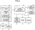
- FIG. 2 is a functional block diagram of the outdoor controller and the water temperature controller according to the embodiment.
- the outdoor controller 50 includes, as illustrated in FIG. 2 , an outdoor control unit 70, a freezing determination unit 71, a low-pressure protection value correction unit 72, and an anti-freezing control unit 73. Further, the compressor 10 and the low-pressure sensor 42 are connected to the outdoor controller 50. Here, other devices connected to the outdoor controller 50 are omitted.
- the water temperature controller 58 includes a water temperature control regulation unit 80 which is able to communicate with the outdoor controller 50 and controls the operation of the water temperature control unit 40 in cooperation with the outdoor control unit 70 of the outdoor controller 50.
- the water temperature control expansion valve 52, the bypass valve 54, the circulation pump 61, the inlet refrigerant temperature sensor 56, and the outlet refrigerant temperature sensor 57 are connected to the water temperature controller 58.
- other devices connected to the water temperature controller 58 are omitted.
- the outdoor control unit 70 controls an entire operation of the air conditioner 1.
- the freezing determination unit 71 determines whether the water flowing through the water heat exchanger 51 is going to be frozen during the cooling operation of the water temperature control unit 40 or the defrost operation of the outdoor heat exchanger 13.
- the possibility of the freezing of the water is determined on the basis of the pressure of the refrigerant circulated between the units. According to this configuration, it is possible to detect the possibility that the water is going to be partly frozen in the microscopic structure inside the water heat exchanger 51 even when the refrigerant circulation amount is small and the refrigerant temperature cannot be highly accurately detected by, for example, the inlet refrigerant temperature sensor 56 and the outlet refrigerant temperature sensor 57 so that the possibility of the freezing of the water cannot be detected.
- the freezing determination unit 71 compares a low pressure LP of the low pressure refrigerant detected by the low-pressure sensor 42 with a predetermined low pressure-protection value LP phmu and determines that the water is going to be frozen when the low pressure LP is lower than the low-pressure protection value LP phmu .
- the low-pressure protection value LP phmu is a reference value which is set in consideration of the pressure loss of the refrigerant generated when the refrigerant flows through the unit connection pipe 6 connecting the outdoor unit 2 and the water temperature control unit 40 to each other.
- the low pressure LP of the low pressure refrigerant which is detected by the low-pressure sensor 42 is being a value which is lower by the pressure loss than the pressure of the refrigerant flowing through the water heat exchanger 51. For this reason, a value obtained by subtracting a value corresponding to the pressure loss from the value of the low pressure LP is set as the low-pressure protection value LP phmu and the possibility of the freezing of the water is determined on the basis of the low-pressure protection value LP phmu . Accordingly, it is possible to simply and highly accurately determine whether the water inside the water heat exchanger 51 is going to be frozen even in a configuration in which the water temperature control unit 40 is disposed at a position separated from the outdoor unit 2.
- the low-pressure protection value correction unit 72 corrects the low-pressure protection value LP phmu in accordance with the operation state of the water temperature control unit 40.
- the pressure loss of the refrigerant changes in accordance with the amount of the refrigerant flowing through the unit connection pipe 6. Therefore, it is possible to improve the accuracy of the low-pressure protection value LP phmu serving as a reference value used to determine the possibility of the freezing of the water by correcting the low-pressure protection value LP phmu in accordance with the operation state of the water temperature control unit 40.
- the anti-freezing control unit 73 performs an anti-freezing operation to prevent the water from being frozen when the possibility of the freezing of the water is determined under the control of the outdoor control unit 70. A detailed operation will be described below.
- the water temperature control regulation unit 80 of the water temperature control unit 40 monitors the inlet temperature and the outlet temperature of the refrigerant flowing through the water heat exchanger 51 by the use of the inlet refrigerant temperature sensor 56 and the outlet refrigerant temperature sensor 57. Further, the water temperature control regulation unit 80 stores a freezing reference temperature, an anti-frost temperature, and an anti-frost cancellation temperature which are set in advance. The water temperature control regulation unit 80 outputs a signal to the outdoor control unit 70 whenever the detected inlet temperature or outlet temperature of the refrigerant reaches the freezing reference temperature, the anti-frost temperature, or the anti-frost cancellation temperature.
- the freezing reference temperature indicates a temperature at which the water inside the water heat exchanger 51 is going to be frozen with high possibility when the inlet temperature or the outlet temperature of the refrigerant flowing through the water heat exchanger 51 falls to the freezing reference temperature, the freezing reference temperature is set to 0°C in the embodiment.
- the water temperature control regulation unit 80 performs a thermo-off operation of the water temperature control unit 40 in order to stop the operation of the water temperature control unit 40. Further, the water temperature control regulation unit 80 may perform a control in which the water temperature control expansion valve 52 is closed and the bypass valve 54 is opened instead of the thermo-off operation.
- the anti-frost temperature indicates a temperature at which the water inside the water heat exchanger 51 is expected to be going to be frozen.
- the anti-frost temperature is set to a temperature higher than the freezing reference temperature (in the embodiment, 3°C) and is used to correct the low-pressure protection value LP phmu .
- the anti-frost cancellation temperature indicates a temperature at which the water inside the water heat exchanger 51 is expected not going to be frozen and is set to a temperature higher than the anti-frost temperature (in the embodiment, 5°C).
- the determination process operation is performed in an operation in which the water heat exchanger 51 of the water temperature control unit 40 serves as the evaporator.
- the defrost operation of the outdoor heat exchanger 13 will be exemplified.
- the water temperature control regulation unit 80 monitors the inlet temperature and the outlet temperature of the refrigerant flowing through the water heat exchanger 51.
- the freezing determination unit 71 acquires the low pressure LP of the low pressure refrigerant detected by the low-pressure sensor 42 and reads the predetermined low-pressure protection value LP phmu during the defrost operation. The freezing determination unit 71 thereby monitors whether the low pressure LP becomes lower than the low-pressure protection value LP phmu .
- the low-pressure protection value correction unit 72 corrects the low-pressure protection value LP phmu on the basis of the monitored refrigerant temperature. Specifically, when the inlet temperature and the outlet temperature of the refrigerant fall to the anti-frost temperature, the low-pressure protection value LP phmu is corrected to a value obtained by adding a predetermined value to the former value.
- the low-pressure protection value LP phmu is corrected to a value obtained by subtracting a predetermined value from the former value after this state is continued for a predetermined time. In this way, since the low-pressure protection value LP phmu is corrected on the basis of the temperature of the refrigerant flowing through the water heat exchanger 51, it is possible to further improve the determination accuracy in the possibility of the freezing of the water.
- the freezing determination unit 71 determines that the water is going to be frozen when the low pressure LP becomes lower than the low-pressure protection value LP phmu . Then, the anti-freezing control unit 73 performs a control so that the low pressure LP rises to a value equal to or larger than the low-pressure protection value LP phmu by decreasing the operation frequency (ability) of the compressor 10. Further, the anti-freezing control unit 73 performs a control in which the water temperature control expansion valve 52 is closed and the bypass valve 54 is opened through the water temperature control regulation unit 80 along with the operation frequency control of the compressor 10.
- the refrigerant flows through the bypass pipe 53, it is possible to prevent the refrigerant from flowing into the water heat exchanger 51 and to prevent the water flowing through the water heat exchanger 51 from being frozen. Further, since the high-temperature refrigerant bypasses the water heat exchanger 51, it is possible to expect a case where an operation point changes in a direction in which the freezing of the water is prevented in accordance with an increase in low pressure of the air conditioner 1. Furthermore, since heat can be drawn from the indoor air by the heat exchange between the refrigerant and the indoor air at the indoor heat exchangers 30 of the indoor units 3A and 3B in the defrost operation, it is possible to continuously perform the defrost operation without stopping the outdoor unit 2 or the indoor units 3A and 3B.
- FIG. 3 is a circuit configuration diagram of a refrigeration cycle device according to the other embodiment.
- a refrigeration cycle device 1A includes one outdoor unit 2 and a plurality of (two in FIG. 3 ) water temperature control units 40A and 40B which are connected in parallel to the outdoor unit 2. That is, the refrigeration cycle device 1A does not include an indoor unit differently from the air conditioner 1.
- the configurations of the outdoor unit 2 and the water temperature control units 40A and 40B are similar to those of the above-described examples and the water temperature control units 40A and 40B are connected to a branching device through branch gas pipes 133A and 133B and branch liquid pipes 134A and 134B.
- the same reference numerals will be given to the other components and a description thereof will be omitted.
- the embodiment has a feature in an anti-freezing process operation, but since a determination process of determining whether water is going to be frozen is the same, a description thereof will be omitted.
- the air conditioner 1 determines that water is going to be frozen when the low pressure LP becomes lower than the low-pressure protection value LP phmu during the defrost operation and performs a control so that the water temperature control expansion valve 52 is closed and the bypass valve 54 is opened via the water temperature control regulation unit 80. Accordingly, the defrost operation can be continuously performed in such a manner that the indoor heat exchangers 30 of the indoor units 3A and 3B draw heat from indoor air.
- the refrigeration cycle device 1A since the refrigeration cycle device 1A according to the other embodiment includes the water temperature control units 40A and 40B and does not include the indoor unit, heat cannot be drawn from the indoor air. For this reason, when it is determined that water is going to be frozen, the anti-freezing control unit 73 can increase a temperature of the refrigerant flowing through the refrigeration circuit to a freezing determination temperature or more by decreasing an operation frequency (ability) of the compressor 10. Additionally, the anti-freezing control unit 73 performs a control so that the circulation pump 61 is continuously operated via the water temperature control regulation unit 80. Accordingly, water which is heated by the water temperature control tank 60 is supplied to the water heat exchanger 51 via the water circulation path 63 in a circulation manner. For this reason, since the refrigerant which flows into the water heat exchanger 51 can draw heat from the heated water while exchanging heat with the circulated water, the defrost operation can be continued without the stop of the outdoor unit 2.
- each of the air conditioner 1 and the refrigeration cycle device 1A includes the outdoor unit 2 which includes the compressor 10 compressing a refrigerant and the outdoor heat exchanger 13 exchanging heat between a refrigerant and external air and the water temperature control unit 40 which includes the water heat exchanger 51 connected to the outdoor unit 2 through the unit connection pipe 6.
- the water heat exchanger 51 exchanges heat between water and a refrigerant supplied from the outdoor unit 2.
- Each of the air conditioner 1 and the refrigeration cycle device 1A further includes the low-pressure sensor 42 which detects a low pressure LP of a refrigerant at a suction side of the compressor 10 and the freezing determination unit 71.
- the freezing determination unit 71 determines that water flowing through the water heat exchanger 51 is going to be frozen when the low pressure LP is lower than a predetermined low-pressure protection value LP phmu during an operation in which the water heat exchanger 51 serves as an evaporator.
- the low-pressure protection value LP phmu is set in consideration of pressure loss generated when a refrigerant flows through the unit connection pipe 6 during an operation in which the water heat exchanger 51 serves as an evaporator. Thereby it is possible to highly accurately determine whether water in the water heat exchanger 51 is going to be frozen even in a configuration in which the water temperature control unit 40 is disposed at a position separated from the outdoor unit 2.
- the low-pressure protection value correction unit 72 which corrects the low-pressure protection value LP phmu to a high value when a temperature of the refrigerant flowing through the water heat exchanger 51 falls to the anti-frost temperature higher than the freezing reference temperature of the water, and corrects the low-pressure protection value LP phmu to a low value when the temperature of the refrigerant rises to the anti-frost cancellation temperature higher than the anti-frost temperature.
- the low-pressure protection value correction unit 72 is provided which corrects the low-pressure protection value LP phmu to a high value when a temperature of the refrigerant flowing through the water heat exchanger 51 falls to the anti-frost temperature higher than the freezing reference temperature of the water, and corrects the low-pressure protection value LP phmu to a low value when the temperature of the refrigerant rises to the anti-frost cancellation temperature higher than the anti-frost temperature.
- the indoor units 3A and 3B which are connected to the outdoor unit 2 in parallel to the water temperature control unit 40 includes the indoor heat exchanger 30 exchanging heat between a refrigerant and indoor air is provided.
- the water temperature control unit 40 includes the water temperature control expansion valve 52 which is provided at a refrigerant inlet side of the water heat exchanger 51, the bypass pipe 53 which bypasses the water temperature control expansion valve 52 and the water heat exchanger 51, and the bypass valve 54 which is provided in the bypass pipe 53.
- the anti-freezing control unit 73 is provided which prevents water from being frozen by closing the water temperature control expansion valve 52 and opening the bypass valve 54 when the freezing determination unit 71 determines that water flowing through the water heat exchanger 51 is going to be frozen.
- the water temperature control unit 40 includes the water circulation path 63 which supplies water to the water heat exchanger 51 in a circulation manner.
- the anti-freezing control unit 73 is provided which prevents water from being frozen by decreasing the ability of the compressor 10 and supplying water to the water heat exchanger 51 in a circulation manner when the freezing determination unit 71 determines that water flowing through the water heat exchanger 51 is going to be frozen. Thereby it is possible to decrease an amount of a refrigerant flowing into the water heat exchanger 51. Further, since the refrigerant flowing into the water heat exchanger 51 exchanges heat with circulated water, it is possible to prevent water flowing through the water heat exchanger 51 from being frozen without disturbing the operation of the outdoor unit 2.
- the embodiment is merely an example and does not limit the scope of the invention.
- the embodiment can be modified into various forms and various omissions, substitutions, and modifications can be made without departing from the scope of the invention as defined by the claims.
- the embodiment or the modification thereof is included in the scope of the invention, the embodiment or the modification thereof is also included in the invention of claims and the equivalent thereof.
- the defrost operation has been described as an operation in which the water heat exchanger 51 of the water temperature control unit 40 serves as the evaporator, but a water cooling operation may be, of course, used.
Claims (5)
- Dispositif à cycle de réfrigération (1) comprenant une unité extérieure (2) qui comprend un compresseur (10) qui comprime un réfrigérant et un échangeur de chaleur extérieur (13) qui échange de la chaleur entre un réfrigérant et de l'air extérieure et une unité de commande de température d'eau (40) qui comprend un échangeur de chaleur à eau relié à l'unité extérieure (2) par l'intermédiaire d'un tuyau de raccordement d'unité (6), l'échangeur de chaleur à eau (51) échangeant de la chaleur entre de l'eau et le réfrigérant délivré à partir de l'unité extérieure (2), le dispositif de cycle de réfrigération (1) comporte :une unité de détection de basse pression qui est configurée pour détecter une basse pression du réfrigérant au niveau d'un côté d'aspiration du compresseur (10) ; etle dispositif de cycle de réfrigération étant caractérisé en ce qu'il comporte :
une unité de détermination de congélation (71) qui est configurée pour déterminer que l'eau qui s'écoule à travers l'échangeur de chaleur à eau (51) va être gelée quand la basse pression est inférieure à une valeur de protection de basse pression prédéterminée pendant un fonctionnement dans lequel l'échangeur de chaleur à eau (51) sert d'évaporateur, la valeur de protection de basse pression étant établie compte tenu de la perte de pression générée par l'écoulement du réfrigérant à travers le tuyau de raccordement d'unité (6). - Dispositif à cycle de réfrigération (1) selon la revendication 1, comportant en outre :
une unité de correction de valeur de protection de basse pression (72) qui est configurée pour corriger la valeur de protection de basse pression à une valeur élevée quand une température du réfrigérant qui s'écoule à travers l'échangeur de chaleur à eau (51) diminue à une température anti-gel plus élevée qu'une température de référence de congélation de l'eau, et est configurée pour corriger la valeur de protection de basse pression à une valeur basse quand une température du réfrigérant augmente jusqu'à une température d'annulation anti-gel plus élevée que la température anti-gel. - Dispositif à cycle de réfrigération (1) selon la revendication 1 ou 2, comportant en outre :une unité intérieure (3A, 3B) qui est reliée à l'unité extérieure (2) en parallèle à l'unité de commande de température d'eau (40) et comprend un échangeur de chaleur intérieur (30) échangeant de la chaleur entre le réfrigérant et de l'air d'intérieur,dans lequel l'unité de commande de température d'eau (40) comprend une soupape de commande qui est prévue sur un côté d'entrée de réfrigérant de l'échangeur de chaleur à eau (51), un tuyau de dérivation (53) qui est configuré pour contourner la soupape de commande et l'échangeur de chaleur à eau (51), et une soupape de dérivation (54) qui est prévue dans le tuyau de dérivation, etdans lequel le dispositif à cycle de réfrigération (1) comporte en outre une unité de commande anti-gel (73) qui empêche de l'eau d'être gelée en fermant la soupape de commande et en ouvrant la soupape de dérivation (54) quand l'unité de détermination de congélation (71) détermine que l'eau qui s'écoule à travers l'échangeur de chaleur à eau (51) va être gelée.
- Dispositif à cycle de réfrigération (1) selon la revendication 1 ou 2,
dans lequel l'unité de commande de température d'eau (40) comprend un passage de circulation de l'eau qui est configuré pour délivrer de l'eau à l'échangeur de chaleur à eau (51) d'une manière avec circulation, et
dans lequel le dispositif de cycle de réfrigération (1) comporte en outre une unité de commande anti-gel (73) qui est configurée pour empêcher l'eau d'être gelée en diminuant une capacité du compresseur (10) et en délivrant l'eau à l'échangeur de chaleur à eau (51) d'une manière avec circulation quand l'unité de détermination de congélation (71) détermine que l'eau qui s'écoule à travers l'échangeur de chaleur à eau (51) va être gelée. - Dispositif à cycle de réfrigération (1) selon l'une quelconque des revendications 1 à 4, dans lequel l'opération dans laquelle l'échangeur de chaleur à eau (51) sert d'évaporateur comprend une opération de dégivrage destinée à empêcher un givrage de l'échangeur de chaleur extérieur (13).
Applications Claiming Priority (1)
| Application Number | Priority Date | Filing Date | Title |
|---|---|---|---|
| JP2016024906A JP2017142038A (ja) | 2016-02-12 | 2016-02-12 | 冷凍サイクル装置 |
Publications (2)
| Publication Number | Publication Date |
|---|---|
| EP3205954A1 EP3205954A1 (fr) | 2017-08-16 |
| EP3205954B1 true EP3205954B1 (fr) | 2018-05-09 |
Family
ID=58009742
Family Applications (1)
| Application Number | Title | Priority Date | Filing Date |
|---|---|---|---|
| EP17155400.9A Active EP3205954B1 (fr) | 2016-02-12 | 2017-02-09 | Dispositif de circuit de réfrigération |
Country Status (3)
| Country | Link |
|---|---|
| EP (1) | EP3205954B1 (fr) |
| JP (1) | JP2017142038A (fr) |
| ES (1) | ES2675039T3 (fr) |
Families Citing this family (11)
| Publication number | Priority date | Publication date | Assignee | Title |
|---|---|---|---|---|
| CN108151367B (zh) * | 2017-12-25 | 2020-12-11 | 北京中矿博能节能科技有限公司 | 直冷式深焓取热乏风热泵系统除霜群控方法 |
| CN110749072A (zh) * | 2018-07-23 | 2020-02-04 | 青岛海尔空调电子有限公司 | 空调器及其室外机除霜控制方法 |
| EP4027076A4 (fr) * | 2019-09-05 | 2023-10-11 | Toshiba Carrier Corporation | Dispositif à cycle frigorifique |
| KR20210085443A (ko) | 2019-12-30 | 2021-07-08 | 엘지전자 주식회사 | 공기조화장치 |
| JP7367216B2 (ja) * | 2020-06-09 | 2023-10-23 | 三菱電機株式会社 | 冷凍サイクル装置 |
| CN113483451B (zh) * | 2021-07-12 | 2022-06-14 | 珠海格力电器股份有限公司 | 空调运行的控制方法、模组、空调和计算机存储介质 |
| CN113503628B (zh) * | 2021-07-13 | 2022-06-14 | 珠海格力电器股份有限公司 | 空调机组参数的调整方法和装置、电子设备和存储介质 |
| CN114992801B (zh) * | 2022-05-10 | 2024-03-22 | 青岛海尔空调电子有限公司 | 空调系统及其控制方法 |
| CN115183403A (zh) * | 2022-07-08 | 2022-10-14 | 青岛海尔空调电子有限公司 | 用于空气源热泵机组防冻的方法及装置、空气源热泵机组、存储介质 |
| CN115183405A (zh) * | 2022-07-08 | 2022-10-14 | 青岛海尔空调电子有限公司 | 用于空气源热泵机组防冻的方法及装置、空气源热泵机组、存储介质 |
| CN115823786A (zh) * | 2022-12-08 | 2023-03-21 | 珠海格力电器股份有限公司 | 一种机组防冻控制方法、装置及冷水机组 |
Family Cites Families (10)
| Publication number | Priority date | Publication date | Assignee | Title |
|---|---|---|---|---|
| JP4032130B2 (ja) * | 2001-11-13 | 2008-01-16 | 株式会社日立製作所 | 冷凍装置 |
| JP4823264B2 (ja) | 2008-03-31 | 2011-11-24 | 三菱電機株式会社 | 冷却装置および冷却装置監視システム |
| JP5220045B2 (ja) * | 2010-02-15 | 2013-06-26 | 三菱電機株式会社 | 冷却装置 |
| EP2781854B1 (fr) * | 2011-11-18 | 2019-07-17 | Mitsubishi Electric Corporation | Climatiseur |
| EP2863152B1 (fr) * | 2012-05-30 | 2020-09-09 | Mitsubishi Electric Corporation | Dispositif de conditionnement d'air |
| WO2014049673A1 (fr) * | 2012-09-25 | 2014-04-03 | 三菱電機株式会社 | Système pour alimentation en eau chaude et pour conditionnement d'air combinés |
| JP6129520B2 (ja) * | 2012-11-16 | 2017-05-17 | 三菱重工業株式会社 | マルチ型空気調和機及びマルチ型空気調和機の制御方法 |
| JP5984965B2 (ja) * | 2012-12-11 | 2016-09-06 | 三菱電機株式会社 | 空調給湯複合システム |
| WO2015056704A1 (fr) * | 2013-10-17 | 2015-04-23 | 東芝キヤリア株式会社 | Dispositif à cycle de réfrigération |
| JP2016008743A (ja) * | 2014-06-23 | 2016-01-18 | パナソニックIpマネジメント株式会社 | 空気調和装置及び冷媒分配ユニット |
-
2016
- 2016-02-12 JP JP2016024906A patent/JP2017142038A/ja active Pending
-
2017
- 2017-02-09 ES ES17155400.9T patent/ES2675039T3/es active Active
- 2017-02-09 EP EP17155400.9A patent/EP3205954B1/fr active Active
Non-Patent Citations (1)
| Title |
|---|
| None * |
Also Published As
| Publication number | Publication date |
|---|---|
| EP3205954A1 (fr) | 2017-08-16 |
| JP2017142038A (ja) | 2017-08-17 |
| ES2675039T3 (es) | 2018-07-05 |
Similar Documents
| Publication | Publication Date | Title |
|---|---|---|
| EP3205955A1 (fr) | Climatiseur d'air | |
| EP3205954B1 (fr) | Dispositif de circuit de réfrigération | |
| EP3467406B1 (fr) | Climatiseur | |
| US9068766B2 (en) | Air-conditioning and hot water supply combination system | |
| EP3279580B1 (fr) | Dispositif de climatisation | |
| EP2933588B1 (fr) | Système composite de climatisation et d'approvisionnement d'eau chaude | |
| US10208987B2 (en) | Heat pump with an auxiliary heat exchanger for compressor discharge temperature control | |
| JP7186845B2 (ja) | 空気調和装置 | |
| US20200271344A1 (en) | Air-conditioning apparatus | |
| KR20090098691A (ko) | 공기 조화 장치 및 그 어큐뮬레이터 | |
| US20180372379A1 (en) | Air conditioner | |
| EP3361190B1 (fr) | Dispositif à cycles de réfrigération et procédé de commande pour déterminer des fuites dans la soupape de dérivation du dispositif à cycles de réfrigération | |
| EP2963359A1 (fr) | Dispositif de climatisation | |
| US20200064040A1 (en) | Refrigeration cycle apparatus | |
| US20170089614A1 (en) | Refrigeration device | |
| EP3109566B1 (fr) | Dispositif de climatisation | |
| EP3657097A1 (fr) | Congélateur | |
| KR102082881B1 (ko) | 냉난방 동시형 멀티 공기조화기 | |
| CN109312961B (zh) | 制冷装置的热源机组 | |
| EP3236168B1 (fr) | Dispositif de climatisation | |
| KR20190041091A (ko) | 공기조화기 | |
| KR102390900B1 (ko) | 멀티형 공기조화기 및 그의 제어방법 | |
| CN109564033A (zh) | 热泵装置 | |
| JP6537629B2 (ja) | 空気調和装置 | |
| JP6573723B2 (ja) | 空気調和装置 |
Legal Events
| Date | Code | Title | Description |
|---|---|---|---|
| PUAI | Public reference made under article 153(3) epc to a published international application that has entered the european phase |
Free format text: ORIGINAL CODE: 0009012 |
|
| STAA | Information on the status of an ep patent application or granted ep patent |
Free format text: STATUS: REQUEST FOR EXAMINATION WAS MADE |
|
| 17P | Request for examination filed |
Effective date: 20170209 |
|
| AK | Designated contracting states |
Kind code of ref document: A1 Designated state(s): AL AT BE BG CH CY CZ DE DK EE ES FI FR GB GR HR HU IE IS IT LI LT LU LV MC MK MT NL NO PL PT RO RS SE SI SK SM TR |
|
| AX | Request for extension of the european patent |
Extension state: BA ME |
|
| GRAP | Despatch of communication of intention to grant a patent |
Free format text: ORIGINAL CODE: EPIDOSNIGR1 |
|
| STAA | Information on the status of an ep patent application or granted ep patent |
Free format text: STATUS: GRANT OF PATENT IS INTENDED |
|
| INTG | Intention to grant announced |
Effective date: 20171201 |
|
| GRAS | Grant fee paid |
Free format text: ORIGINAL CODE: EPIDOSNIGR3 |
|
| GRAA | (expected) grant |
Free format text: ORIGINAL CODE: 0009210 |
|
| STAA | Information on the status of an ep patent application or granted ep patent |
Free format text: STATUS: THE PATENT HAS BEEN GRANTED |
|
| AK | Designated contracting states |
Kind code of ref document: B1 Designated state(s): AL AT BE BG CH CY CZ DE DK EE ES FI FR GB GR HR HU IE IS IT LI LT LU LV MC MK MT NL NO PL PT RO RS SE SI SK SM TR |
|
| REG | Reference to a national code |
Ref country code: GB Ref legal event code: FG4D |
|
| REG | Reference to a national code |
Ref country code: CH Ref legal event code: EP Ref country code: AT Ref legal event code: REF Ref document number: 997949 Country of ref document: AT Kind code of ref document: T Effective date: 20180515 |
|
| REG | Reference to a national code |
Ref country code: IE Ref legal event code: FG4D |
|
| REG | Reference to a national code |
Ref country code: DE Ref legal event code: R096 Ref document number: 602017000051 Country of ref document: DE |
|
| REG | Reference to a national code |
Ref country code: ES Ref legal event code: FG2A Ref document number: 2675039 Country of ref document: ES Kind code of ref document: T3 Effective date: 20180705 |
|
| REG | Reference to a national code |
Ref country code: NL Ref legal event code: MP Effective date: 20180509 |
|
| REG | Reference to a national code |
Ref country code: LT Ref legal event code: MG4D |
|
| PG25 | Lapsed in a contracting state [announced via postgrant information from national office to epo] |
Ref country code: LT Free format text: LAPSE BECAUSE OF FAILURE TO SUBMIT A TRANSLATION OF THE DESCRIPTION OR TO PAY THE FEE WITHIN THE PRESCRIBED TIME-LIMIT Effective date: 20180509 Ref country code: SE Free format text: LAPSE BECAUSE OF FAILURE TO SUBMIT A TRANSLATION OF THE DESCRIPTION OR TO PAY THE FEE WITHIN THE PRESCRIBED TIME-LIMIT Effective date: 20180509 Ref country code: FI Free format text: LAPSE BECAUSE OF FAILURE TO SUBMIT A TRANSLATION OF THE DESCRIPTION OR TO PAY THE FEE WITHIN THE PRESCRIBED TIME-LIMIT Effective date: 20180509 Ref country code: NO Free format text: LAPSE BECAUSE OF FAILURE TO SUBMIT A TRANSLATION OF THE DESCRIPTION OR TO PAY THE FEE WITHIN THE PRESCRIBED TIME-LIMIT Effective date: 20180809 Ref country code: BG Free format text: LAPSE BECAUSE OF FAILURE TO SUBMIT A TRANSLATION OF THE DESCRIPTION OR TO PAY THE FEE WITHIN THE PRESCRIBED TIME-LIMIT Effective date: 20180809 |
|
| PG25 | Lapsed in a contracting state [announced via postgrant information from national office to epo] |
Ref country code: RS Free format text: LAPSE BECAUSE OF FAILURE TO SUBMIT A TRANSLATION OF THE DESCRIPTION OR TO PAY THE FEE WITHIN THE PRESCRIBED TIME-LIMIT Effective date: 20180509 Ref country code: NL Free format text: LAPSE BECAUSE OF FAILURE TO SUBMIT A TRANSLATION OF THE DESCRIPTION OR TO PAY THE FEE WITHIN THE PRESCRIBED TIME-LIMIT Effective date: 20180509 Ref country code: LV Free format text: LAPSE BECAUSE OF FAILURE TO SUBMIT A TRANSLATION OF THE DESCRIPTION OR TO PAY THE FEE WITHIN THE PRESCRIBED TIME-LIMIT Effective date: 20180509 Ref country code: HR Free format text: LAPSE BECAUSE OF FAILURE TO SUBMIT A TRANSLATION OF THE DESCRIPTION OR TO PAY THE FEE WITHIN THE PRESCRIBED TIME-LIMIT Effective date: 20180509 Ref country code: GR Free format text: LAPSE BECAUSE OF FAILURE TO SUBMIT A TRANSLATION OF THE DESCRIPTION OR TO PAY THE FEE WITHIN THE PRESCRIBED TIME-LIMIT Effective date: 20180810 |
|
| REG | Reference to a national code |
Ref country code: AT Ref legal event code: MK05 Ref document number: 997949 Country of ref document: AT Kind code of ref document: T Effective date: 20180509 |
|
| PG25 | Lapsed in a contracting state [announced via postgrant information from national office to epo] |
Ref country code: SK Free format text: LAPSE BECAUSE OF FAILURE TO SUBMIT A TRANSLATION OF THE DESCRIPTION OR TO PAY THE FEE WITHIN THE PRESCRIBED TIME-LIMIT Effective date: 20180509 Ref country code: RO Free format text: LAPSE BECAUSE OF FAILURE TO SUBMIT A TRANSLATION OF THE DESCRIPTION OR TO PAY THE FEE WITHIN THE PRESCRIBED TIME-LIMIT Effective date: 20180509 Ref country code: AT Free format text: LAPSE BECAUSE OF FAILURE TO SUBMIT A TRANSLATION OF THE DESCRIPTION OR TO PAY THE FEE WITHIN THE PRESCRIBED TIME-LIMIT Effective date: 20180509 Ref country code: EE Free format text: LAPSE BECAUSE OF FAILURE TO SUBMIT A TRANSLATION OF THE DESCRIPTION OR TO PAY THE FEE WITHIN THE PRESCRIBED TIME-LIMIT Effective date: 20180509 Ref country code: PL Free format text: LAPSE BECAUSE OF FAILURE TO SUBMIT A TRANSLATION OF THE DESCRIPTION OR TO PAY THE FEE WITHIN THE PRESCRIBED TIME-LIMIT Effective date: 20180509 Ref country code: DK Free format text: LAPSE BECAUSE OF FAILURE TO SUBMIT A TRANSLATION OF THE DESCRIPTION OR TO PAY THE FEE WITHIN THE PRESCRIBED TIME-LIMIT Effective date: 20180509 Ref country code: CZ Free format text: LAPSE BECAUSE OF FAILURE TO SUBMIT A TRANSLATION OF THE DESCRIPTION OR TO PAY THE FEE WITHIN THE PRESCRIBED TIME-LIMIT Effective date: 20180509 |
|
| REG | Reference to a national code |
Ref country code: DE Ref legal event code: R097 Ref document number: 602017000051 Country of ref document: DE |
|
| PG25 | Lapsed in a contracting state [announced via postgrant information from national office to epo] |
Ref country code: SM Free format text: LAPSE BECAUSE OF FAILURE TO SUBMIT A TRANSLATION OF THE DESCRIPTION OR TO PAY THE FEE WITHIN THE PRESCRIBED TIME-LIMIT Effective date: 20180509 Ref country code: IT Free format text: LAPSE BECAUSE OF FAILURE TO SUBMIT A TRANSLATION OF THE DESCRIPTION OR TO PAY THE FEE WITHIN THE PRESCRIBED TIME-LIMIT Effective date: 20180509 |
|
| PLBE | No opposition filed within time limit |
Free format text: ORIGINAL CODE: 0009261 |
|
| STAA | Information on the status of an ep patent application or granted ep patent |
Free format text: STATUS: NO OPPOSITION FILED WITHIN TIME LIMIT |
|
| 26N | No opposition filed |
Effective date: 20190212 |
|
| PG25 | Lapsed in a contracting state [announced via postgrant information from national office to epo] |
Ref country code: LU Free format text: LAPSE BECAUSE OF NON-PAYMENT OF DUE FEES Effective date: 20190209 Ref country code: MC Free format text: LAPSE BECAUSE OF FAILURE TO SUBMIT A TRANSLATION OF THE DESCRIPTION OR TO PAY THE FEE WITHIN THE PRESCRIBED TIME-LIMIT Effective date: 20180509 |
|
| REG | Reference to a national code |
Ref country code: BE Ref legal event code: MM Effective date: 20190228 |
|
| REG | Reference to a national code |
Ref country code: IE Ref legal event code: MM4A |
|
| PG25 | Lapsed in a contracting state [announced via postgrant information from national office to epo] |
Ref country code: AL Free format text: LAPSE BECAUSE OF FAILURE TO SUBMIT A TRANSLATION OF THE DESCRIPTION OR TO PAY THE FEE WITHIN THE PRESCRIBED TIME-LIMIT Effective date: 20180509 |
|
| PG25 | Lapsed in a contracting state [announced via postgrant information from national office to epo] |
Ref country code: IE Free format text: LAPSE BECAUSE OF NON-PAYMENT OF DUE FEES Effective date: 20190209 |
|
| PG25 | Lapsed in a contracting state [announced via postgrant information from national office to epo] |
Ref country code: FR Free format text: LAPSE BECAUSE OF NON-PAYMENT OF DUE FEES Effective date: 20190228 Ref country code: BE Free format text: LAPSE BECAUSE OF NON-PAYMENT OF DUE FEES Effective date: 20190228 |
|
| PG25 | Lapsed in a contracting state [announced via postgrant information from national office to epo] |
Ref country code: MT Free format text: LAPSE BECAUSE OF NON-PAYMENT OF DUE FEES Effective date: 20190209 Ref country code: PT Free format text: LAPSE BECAUSE OF FAILURE TO SUBMIT A TRANSLATION OF THE DESCRIPTION OR TO PAY THE FEE WITHIN THE PRESCRIBED TIME-LIMIT Effective date: 20180910 |
|
| REG | Reference to a national code |
Ref country code: CH Ref legal event code: PL |
|
| PG25 | Lapsed in a contracting state [announced via postgrant information from national office to epo] |
Ref country code: CH Free format text: LAPSE BECAUSE OF NON-PAYMENT OF DUE FEES Effective date: 20200229 Ref country code: LI Free format text: LAPSE BECAUSE OF NON-PAYMENT OF DUE FEES Effective date: 20200229 |
|
| PG25 | Lapsed in a contracting state [announced via postgrant information from national office to epo] |
Ref country code: CY Free format text: LAPSE BECAUSE OF FAILURE TO SUBMIT A TRANSLATION OF THE DESCRIPTION OR TO PAY THE FEE WITHIN THE PRESCRIBED TIME-LIMIT Effective date: 20180509 |
|
| PG25 | Lapsed in a contracting state [announced via postgrant information from national office to epo] |
Ref country code: IS Free format text: LAPSE BECAUSE OF FAILURE TO SUBMIT A TRANSLATION OF THE DESCRIPTION OR TO PAY THE FEE WITHIN THE PRESCRIBED TIME-LIMIT Effective date: 20180909 |
|
| PG25 | Lapsed in a contracting state [announced via postgrant information from national office to epo] |
Ref country code: HU Free format text: LAPSE BECAUSE OF FAILURE TO SUBMIT A TRANSLATION OF THE DESCRIPTION OR TO PAY THE FEE WITHIN THE PRESCRIBED TIME-LIMIT; INVALID AB INITIO Effective date: 20170209 |
|
| PG25 | Lapsed in a contracting state [announced via postgrant information from national office to epo] |
Ref country code: SI Free format text: LAPSE BECAUSE OF FAILURE TO SUBMIT A TRANSLATION OF THE DESCRIPTION OR TO PAY THE FEE WITHIN THE PRESCRIBED TIME-LIMIT Effective date: 20180509 |
|
| PG25 | Lapsed in a contracting state [announced via postgrant information from national office to epo] |
Ref country code: MK Free format text: LAPSE BECAUSE OF FAILURE TO SUBMIT A TRANSLATION OF THE DESCRIPTION OR TO PAY THE FEE WITHIN THE PRESCRIBED TIME-LIMIT Effective date: 20180509 |
|
| PGFP | Annual fee paid to national office [announced via postgrant information from national office to epo] |
Ref country code: GB Payment date: 20221230 Year of fee payment: 7 |
|
| REG | Reference to a national code |
Ref country code: DE Ref legal event code: R082 Ref document number: 602017000051 Country of ref document: DE Representative=s name: CBDL PATENTANWAELTE GBR, DE |
|
| PGFP | Annual fee paid to national office [announced via postgrant information from national office to epo] |
Ref country code: ES Payment date: 20230310 Year of fee payment: 7 |
|
| PGFP | Annual fee paid to national office [announced via postgrant information from national office to epo] |
Ref country code: TR Payment date: 20230208 Year of fee payment: 7 Ref country code: DE Payment date: 20221229 Year of fee payment: 7 |
|
| PGFP | Annual fee paid to national office [announced via postgrant information from national office to epo] |
Ref country code: ES Payment date: 20240304 Year of fee payment: 8 |