EP3205942A2 - Gargerätsystem und verfahren zum betreiben - Google Patents
Gargerätsystem und verfahren zum betreiben Download PDFInfo
- Publication number
- EP3205942A2 EP3205942A2 EP17150939.1A EP17150939A EP3205942A2 EP 3205942 A2 EP3205942 A2 EP 3205942A2 EP 17150939 A EP17150939 A EP 17150939A EP 3205942 A2 EP3205942 A2 EP 3205942A2
- Authority
- EP
- European Patent Office
- Prior art keywords
- measuring
- cooking
- food
- cooking appliance
- measuring point
- Prior art date
- Legal status (The legal status is an assumption and is not a legal conclusion. Google has not performed a legal analysis and makes no representation as to the accuracy of the status listed.)
- Withdrawn
Links
- 238000010411 cooking Methods 0.000 title claims abstract description 133
- 238000000034 method Methods 0.000 title claims abstract description 23
- 238000010438 heat treatment Methods 0.000 claims abstract description 26
- 230000001419 dependent effect Effects 0.000 claims abstract description 4
- 238000009413 insulation Methods 0.000 claims description 34
- 230000001681 protective effect Effects 0.000 claims description 33
- 238000001514 detection method Methods 0.000 claims description 10
- 238000003780 insertion Methods 0.000 claims description 2
- 230000037431 insertion Effects 0.000 claims description 2
- 238000011156 evaluation Methods 0.000 description 8
- IHQKEDIOMGYHEB-UHFFFAOYSA-M sodium dimethylarsinate Chemical class [Na+].C[As](C)([O-])=O IHQKEDIOMGYHEB-UHFFFAOYSA-M 0.000 description 7
- 230000005540 biological transmission Effects 0.000 description 5
- 238000012544 monitoring process Methods 0.000 description 5
- 238000011161 development Methods 0.000 description 4
- 230000018109 developmental process Effects 0.000 description 4
- 239000000463 material Substances 0.000 description 3
- 238000012913 prioritisation Methods 0.000 description 3
- 238000001035 drying Methods 0.000 description 2
- 238000012935 Averaging Methods 0.000 description 1
- 241000656145 Thyrsites atun Species 0.000 description 1
- 238000009833 condensation Methods 0.000 description 1
- 230000005494 condensation Effects 0.000 description 1
- 238000012937 correction Methods 0.000 description 1
- 230000001771 impaired effect Effects 0.000 description 1
- 238000012423 maintenance Methods 0.000 description 1
- 238000005259 measurement Methods 0.000 description 1
- 238000002360 preparation method Methods 0.000 description 1
- 230000002035 prolonged effect Effects 0.000 description 1
- 230000001012 protector Effects 0.000 description 1
- 239000000523 sample Substances 0.000 description 1
- 238000010025 steaming Methods 0.000 description 1
Images
Classifications
-
- F—MECHANICAL ENGINEERING; LIGHTING; HEATING; WEAPONS; BLASTING
- F24—HEATING; RANGES; VENTILATING
- F24C—DOMESTIC STOVES OR RANGES ; DETAILS OF DOMESTIC STOVES OR RANGES, OF GENERAL APPLICATION
- F24C7/00—Stoves or ranges heated by electric energy
- F24C7/08—Arrangement or mounting of control or safety devices
- F24C7/082—Arrangement or mounting of control or safety devices on ranges, e.g. control panels, illumination
- F24C7/085—Arrangement or mounting of control or safety devices on ranges, e.g. control panels, illumination on baking ovens
Definitions
- the present invention relates to a cooking appliance system and method for operating such.
- the cooking appliance system comprises at least one cooking appliance with at least one heating device and with at least one heatable cooking chamber for the treatment of food to be cooked.
- Cooking appliances are often equipped with automatic programs that facilitate the preparation of food and improve the result of a cooking process. For example, the user selects a product that he wants to prepare from a list and then only has to start the cooking process. All other required settings of the cooking appliance can then be specified by the automatic program, such.
- a control of the cooking process and in particular a targeted control of the oven temperature are necessary, in turn, require the most accurate knowledge of the state of the cooking.
- core temperature probes or humidity sensors are used to draw conclusions about the state of the food of a foodstuff.
- the known sensors are often very expensive and susceptible to interference or often provide insufficient information for a detailed monitoring and determination of the state of the food.
- the cooking appliance system comprises at least one cooking appliance with at least one heating device and with at least one heatable cooking chamber for the treatment of food to be cooked. At least one control device for controlling the heating device is provided.
- the cooking appliance system comprises at least one measuring system with at least one measuring module with at least two measuring points.
- the measuring system is suitable and designed to determine the cooking state of a food.
- the measuring module with the at least two measuring points is suitable and designed, at least one characteristic size for a Temperature to capture.
- the measuring module is suitable and designed to be aligned for use as intended in a measuring position dependent on the food to be cooked.
- the measuring module is suitable and designed to detect at least one measuring point at least one characteristic variable for a surface temperature of the food.
- the measuring module is also suitable and designed to detect at least one characteristic variable for an ambient temperature of the food.
- the cooking appliance system according to the invention has many advantages.
- a significant advantage is that both the surface temperature and the ambient temperature of the food are considered to determine the state of the cooking. Knowing these temperatures, a particularly meaningful and reliable determination of the state of the cooking can take place.
- the surface temperature of the food is a reliable parameter for the degree of browning.
- the ambient temperature is particularly useful for determining whether the desired temperatures for cooking are present on and / or in the food.
- the ambient temperature is also much more reliable for determining the state of the cooking than, for example, a temperature detection on the cooking chamber ceiling, since the ambient temperature depends more on the cooking process.
- the ambient temperature can be used particularly helpful in the case of low-temperature cooking processes, for example.
- the temperature detection takes place with a measuring module, which can be variably aligned to the food to be cooked, so that the best possible measuring position is taken. As a result, the state of the food can be determined particularly well and reliably.
- the orientation of the measuring module in a measuring position that depends on the food to be cooked comprises, in particular, an orientation of the measuring module as a function of the size and / or the shape of the item to be cooked and / or the position of the item to be cooked in the cooking space.
- the measuring module is preferably suitable and designed to be fastened for and intended for use in and / or on the food. For example, at least a part of the measuring module can be inserted into the food. It is also possible that the measuring module is attached indirectly to the food, for example via a fastening device attached to the food.
- the measuring module is particularly suitable and designed to be variably aligned in the cooking chamber.
- the measuring module is not installed stationary in the cooking chamber.
- the measuring module is freely positionable in the cooking chamber.
- the measuring system may comprise at least one fastening device which is suitable and designed to releasably receive the measuring module and to be fastened in a variable position to the food in the cooking chamber.
- the fastening device is attached to a cooking chamber wall and / or to a food support holder and / or to a food support attached.
- the measuring module is designed as a separate accessory module of the cooking appliance.
- the measuring points each comprise at least one sensor.
- a sensor may comprise at least one resistance thermometer and / or at least one thermocouple or the like. It is also possible that the change in a resonance frequency of a resonant circuit as a function of the temperature is detected at the measuring points.
- the cooking device comprises at least one sensor device with at least one sensor unit associated with the cooking chamber for detecting temperatures in the cooking chamber.
- the control device is suitable and designed to control the heating device at least temporarily as a function of the temperature detected by the sensor device.
- the measuring system is in particular suitable and designed to use, at least temporarily, the temperatures detected by the sensor device for determining the state of the cooking.
- Such an embodiment has the advantage that already provided for the cooking device sensors are used to monitor the state of the gas, such as sensors for the temperature control in the oven.
- the measuring system may be suitable and designed to at least temporarily not take into account the temperatures detected by the sensor device.
- the measuring system can also be suitable and designed to prioritize or subordinate the temperatures detected with the sensor device with respect to the temperatures detected with the measuring module.
- the measuring module is wirelessly operatively connected to the measuring system and / or to the control device.
- the measuring system may also include at least one evaluation device for evaluating the data acquired by the measuring module.
- the measuring module is then preferably wirelessly connected to the evaluation device.
- the evaluation device may be at least partially integrated into the control device.
- a passive transmission technique is provided, for.
- the measuring module comprises at least one SAW antenna.
- an at least partially active transmission technology is also possible.
- the measuring module is suitable and designed to use the temperature dependence of the resonant frequency of a resonant circuit for temperature detection. Such a temperature detection is particularly reliable and the measuring module is also very durable and low maintenance.
- the measuring module is at least partially automatically detected and coupled by the measuring system.
- the measuring module can however be connected by a cable to the measuring system and / or the control device. It is possible that the cable connection is in particular tool-free separable by the user and is preferably designed pluggable. But it is also possible a permanently installed cable connection.
- the control device is suitable and designed to control the heating device at least temporarily as a function of the temperatures determined at at least one of the measuring points of the measuring system.
- the temperatures detected with the measuring system can be used particularly advantageously for such an influencing of the heating device, since the control of the heating device has a particularly important influence on the cooking result.
- the control device is suitable and designed to output at least one signal as a function of a temperature detected at at least one of the measuring points.
- the control device is suitable and designed to control in dependence on the temperatures detected at both measuring points.
- the measuring system is suitable and designed to determine the cooking state of the cooking product on the basis of the surface temperature and the ambient temperature of the cooking product.
- the control device is suitable and designed to control the heating device at least temporarily as a function of the determined cooking state and / or to output at least one signal.
- the control device is in particular suitable and designed to determine, depending on a preselected by a user operating mode, which of the at least two measuring points for the control of the heater are taken into account. It is also possible that the control device is suitable and designed to set a prioritization for the consideration of the two measuring points depending on the preselected operating mode. Such embodiments are particularly advantageous since, depending on the mode of operation, it may be more appropriate to consider the surface temperature or the ambient temperature more strongly.
- the ambient temperature of the food can be used particularly well for monitoring low-temperature cooking processes.
- the surface temperature of the food is particularly helpful in monitoring tanning processes, such as barbecuing.
- the control device is suitable and designed to take into account in an operating mode with a low-temperature cooking process only and / or the other measuring point for the ambient temperature.
- the control device is suitable and designed, in an operating mode with a Böstedsgarvon only and / or the one measuring point for the surface temperature to take into account. Also possible is a prioritized consideration of at least one further measuring point.
- the control device is suitable and designed to neglect the temperatures detected in the cooking chamber by the sensor device at least temporarily for the control of the heating device.
- neglecting the temperatures detected by the sensor device takes place when an operating mode is present which takes into account the temperatures detected at the measuring points of the measuring module.
- the control of the heater may occur without regard to the temperatures sensed by the sensor device. It is also possible that the temperatures detected by the sensor device are neglected when the temperatures in the cooking chamber and / or the temperatures detected at the measuring points of the measuring module reach and / or exceed certain threshold values.
- the measuring module is suitable and designed to detect the characteristic size for the surface temperature of the food outside the food.
- detection of the surface temperature from outside the food is particularly reliable and also inexpensive.
- the surface temperature of the food in the immediate vicinity of the surface of the food is detected from outside the food.
- a spacing to the food surface of a few millimeters and / or a few centimeters may be provided.
- the distance of the measuring point for the surface temperature is less than 10 cm, and more preferably less than 5 cm. It is also possible that the measuring point for the surface temperature is spaced less than 2 cm from the food surface. It is also possible that the measuring point at least partially touches the surface of the food.
- the measuring module is suitable and designed to detect the characteristic variable for the surface temperature of the food from within the food.
- the measuring module is particularly suitable and designed to at least approximately determine the surface temperature based on an internal temperature of the food.
- the measuring module has at least one recess section for piercing the food to be cooked. It is also preferred that the measuring module has at least one shank portion provided for the arrangement outside the food to be cooked.
- the measuring module is in particular a cooking thermometer educated. For example, the measuring module may also be used for monitoring the core temperature during frying, for example.
- the puncturing section comprises, for example, a skewer and / or a fork or is designed as such.
- the shank portion is preferably at least partially formed or comprises a handle device.
- the shank portion may also have at least one insulation device for protection against heat. It is also possible at least a protective device that prevents unintentional touching the puncture portion and / or the food during handling.
- the measuring module can also comprise only one gripping device and its outer shape can essentially be formed from one.
- At least one of the at least two measuring points is arranged in the shaft section.
- both measuring points are arranged in the shaft section.
- Such an arrangement of the measuring points is particularly well suited for detecting the surface temperature and the ambient temperature.
- the one measuring point for detecting the surface temperature is arranged in the recess section.
- the measuring point is then arranged at that end of the puncturing section, at which the shaft section adjoins.
- the one of the at least two measuring points is preferably arranged in a third of the shaft section adjoining the puncturing section. Such an arrangement in the vicinity of the puncturing section is particularly advantageous for the detection of the surface temperature, since this measuring point is particularly close to the food to be cooked when a measuring module is inserted.
- the one measuring point is preferably arranged directly adjacent to the puncturing section in the shaft section. It is also possible that the one measuring point is arranged in a quarter or sixth adjacent to the puncturing section and in particular eighth of the shaft section. It is also possible for the one measuring point to be arranged in a half of the shaft section adjoining the puncturing section.
- the other of the at least two measuring points is arranged in a third of the shaft section opposite the puncturing section.
- Such an arrangement of the other measuring point has the advantage that with this measuring point, the ambient temperature of the food can be particularly well detected when the puncture portion is inserted into the food.
- the other measuring point is preferably arranged at an end of the shaft section opposite the puncturing section. It is also possible that the other measuring point in a the Einstichabites opposite quarter or sixth and especially eighth of the shaft portion is arranged.
- At least one measuring point is heat-conductively connected to an outer surface of the shaft section by at least one heat-conducting element.
- both measuring points are connected by the heat-conducting element to the outer surface of the shaft portion.
- the heat-conducting element is made of a material with suitable thermal conductivity.
- the further measuring point is suitable and designed to detect an internal temperature of the food.
- the further measuring point is arranged in particular in the recess section of the measuring module. So z. B. also the internal temperature in the food to be used to determine the state of the cooking.
- the measuring system is particularly suitable and designed to set a prioritization for the use of one and the other and the other measuring point. Such a prioritization takes place in particular as a function of a set operating mode.
- the shaft section has at least one grip device.
- at least one of the at least two measuring points is arranged in the gripping device.
- the measuring point can also be at least partially on the grip device.
- one and the other measuring point are arranged in the gripping device.
- the gripping device extends only over a portion of the shaft portion.
- the shaft section may comprise further sections in addition to the grip device.
- the shaft portion may comprise at least one protective device, which prevents unintentional contact with the puncture portion and / or the food during handling.
- the shank portion comprises only one gripping device and its outer shape is essentially formed from one.
- the grip device comprises at least one protective insulation suitable for safe handling.
- the protective insulation is particularly suitable and designed to allow a safe grip with bare hands even after a prolonged residence of the measuring module at higher temperatures in the oven.
- the protective insulation is arranged at least along the longitudinal sides of the grip device.
- the protective insulation can be arranged along all longitudinal sides of the grip device. It is also possible that the protective insulation along opposite longitudinal sides of the Gripping device is arranged.
- the gripping device is essentially completely and preferably completely encased with the protective insulation.
- the protective insulation has at least one recess in which at least one of the at least two measuring points is arranged.
- the protective insulation for each measuring point in each case at least one recess.
- the protective insulation can also cover the measuring points.
- the protective insulation is arranged, in particular, along a broad side of the gripping device opposite the puncturing section.
- the broad side is in particular a side which runs essentially transversely to the longitudinal side of the grip device. It is also possible for the protective insulation to be arranged along a broad side of the grip device adjoining the puncturing section.
- the protective insulation is preferably arranged both on the broad side opposite the puncturing section and on the broad side of the grip device adjoining the puncturing section.
- the protective insulation can be arranged along all broad sides of the grip device.
- the protective insulation is arranged both on the broad sides and on the longitudinal sides of the grip device.
- a protective insulation on the broad sides then takes place, although a protective insulation along the longitudinal sides is provided.
- At least one thermal insulation device is arranged between the one measuring point and the other measuring point.
- Such an insulating device between the measuring points improves the measuring characteristic in an advantageous manner.
- the temperature contrast between the measuring points is amplified by the insulating device.
- the heat conduction between the measuring points is made more difficult by the thermal insulation device.
- the measuring points in the shaft section are preferably each separated by an insulating device.
- the puncturing section and the shaft section are separated by at least one thermal insulation device.
- the method according to the invention is suitable for operating a cooking appliance system.
- the cooking appliance system comprises at least one cooking appliance with at least one heating device and at least one heatable cooking chamber for the treatment of food to be cooked.
- a cooking state of the food is determined with at least one measuring system with at least one measuring module.
- the measuring module is aligned in a measuring position that depends on the food to be cooked.
- the measuring module is variably aligned to the food in the cooking chamber.
- At least one measuring point of the measuring module at least one characteristic variable for a surface temperature of the cooking product is detected.
- at least one other measuring point of the Measuring module is detected at least one characteristic size for an ambient temperature of the food.
- the inventive method allows a particularly reliable and meaningful temperature detection, so that correspondingly accurate statements about the state of the cooking food are possible. As a result, in particular the control of automatic programs and ultimately also the cooking result can be significantly improved.
- the inventive method is carried out in particular with the cooking appliance system described above.
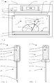
- the FIG. 1 shows a cooking appliance according to the invention a 100 with a cooking appliance 1 and a measuring module 15.
- the cooking appliance 100 is preferably operated by the method according to the invention.
- the cooking appliance 1 comprises a cooking chamber 3, which can be heated by a heating device 2 and closed by a door 102.
- the heating device 2 shown here comprises by way of example a top heat heating source and a bottom heat heating source.
- other heating sources are provided, such as a grill heater and / or a Um Kunststoffutzquelle and / or other thermal heat sources.
- the heating device 2 has a microwave source and / or a steam heating source.
- the cooking appliance 1 can also be designed as a combi appliance, for example as an oven with steaming function and / or microwave function.
- the cooking appliance 1 can be operated via an operating device 101.
- various operating modes, operating temperatures and preferably different program operating modes and automatic functions can be set via the operating device 101.
- the operating device 101 is also equipped with a display device via which the user various information and / or signals about the operation and cooking process are displayed.
- the operating device 101 can also be designed with a touch-sensitive surface or as a so-called touch screen.
- the food to be cooked 300 is located here on an accessory 200 designed as a food support 301.
- the food support 301 is, for example, a grate or a baking tray.
- the food support 301 is accommodated in the cooking chamber 3 on a food support receptacle 23, not shown here.
- a control device 6 is used to control or control various device functions, eg. B. for temperature control and / or for the automatic functions.
- the heating power of the heater 2 is set so that there are 3 temperatures in the cooking chamber, which are in the range of a required set temperature.
- a sensor device 4 may be provided with a sensor unit 14.
- the sensor unit 14 is attached here by way of example to a cooking chamber in the upper region of the cooking chamber 3 and shown in dashed lines.
- the cooking appliance system 100 has a measuring system 5 shown here in a highly schematic manner.
- the measuring system 5 comprises a measuring module 15 with two measuring points 151, 152 and an evaluation module 95 for evaluating the measured data.
- the measuring module 15 is provided here as an accessory module 25 for the cooking device 1 and wirelessly connected to the evaluation module 95.
- a passive transmission technique is preferred on the side of the measuring module 15, a passive transmission technique is preferred. Also possible is an active transmission technology. It can also be a connection of the measuring module 15 by cable.
- the evaluation module 95 is accommodated here in the control device 6 of the cooking appliance 1. At the measuring points 151, 152 of the measuring system 5, characteristic values for temperatures can be detected, which are evaluated by the evaluation module 95 and used to determine the state of cooking of the cooking product 300.
- the measuring module 15 shown here detects at least one characteristic variable for a surface temperature of the food with a first measuring point 151. With another measuring point 152, the measuring module 15 detects at least one characteristic variable for an ambient temperature of the food 300.
- the measuring points 151, 152 each comprise at least one temperature sensor.
- a resistance thermometer can be used. It is also possible that the temperature is detected at the measuring points 151, 152 by registering the change in a resonant frequency of a resonant circuit as a function of the temperature. Also possible are other suitable sensors for temperature detection, such as thermocouples.
- the measuring module 15 is aligned in a measuring position that depends on the food to be cooked 300.
- the measuring module 15 is provided here with a puncture section 35, which is designed as a spit 350. So a particularly simple insertion into the food 300 is possible.
- the measuring points 151, 152 are arranged here in a shank portion 45 of the measuring module 15.
- the shaft section 45 remains with the measuring module inserted 15 outside the food 300.
- the other measuring point 152 is arranged here at the upper end of the shaft portion 45.
- the arrangement of the other measuring point 152 at the opposite end of the shaft portion 45 is particularly advantageous for detecting the ambient temperature, since the measuring point 152 has a sufficient distance from the surface of the food 300 even with fully pierced recess portion 35.
- the spacing of the two measuring points 151, 152 ensures that the conditions prevailing at the respective measuring points 151, 152 do not unfavorably influence one another.
- the one measuring point 151 is here positioned at the lower end of the shaft section 45, which adjoins the puncturing section 35.
- one measuring point 151 is substantially directly adjacent or at least very close to the surface of the food 300 when the measuring module 15 is inserted. This ensures that the temperature detected at one measuring point 151 is essentially determined by the surface temperature of the food 300.
- the puncturing section 35 is inserted as deeply as possible and preferably completely into the food 300.
- the temperatures detected at the measuring points 151, 152 can be evaluated in a variety of ways by the measuring system 5 and used for device control.
- the surface temperature can be used for a specific moistening of the cooking chamber atmosphere during a cooking process.
- the moisture content can be increased if the surface temperature indicates an imminent drying out of the food surface.
- drying out is specifically prevented and, on the other hand, excessive moisture of the surface of the cooking product is avoided.
- the minimum moisture content of the cooking chamber atmosphere is determined as a function of the surface temperature of the cooking product.
- the moisture content can be adjusted by the knowledge of the surface temperature of the food so that a condensation of the moisture is achieved on the food. So can be done by moistening an additional heat input into the food.
- the ambient temperature can also be used, for example, particularly well for controlling the temperature in the cooking chamber 3.
- at least temporarily only the ambient temperature detected at the measuring point 152 can be used for temperature regulation in the cooking chamber 3. Since this measuring point 152 is usually arranged closer to the food 300, as for example the sensor unit 14 of the sensor device 4, thus a temperature control is possible, which reacts very directly to the changes of the food 300. It is also possible that at least temporarily both the measuring point 152 for the ambient temperature and the sensor unit 14 on the cooking chamber wall are used together for temperature control.
- the temperature control can take place on the basis of a calculated value, which results from the measured values registered at the measuring point 152 and the sensor unit 14 taking into account at least one empirical formula, for example a type of weighted averaging.
- the underlying formula can also be implemented in such a way that, for example, it is lighter or more heavily modified depending on the operating mode, oven temperature or automatic program.
- the ambient temperature can also be used during low-temperature cooking, since in this case a temperature control in the vicinity of the food is particularly crucial. For example, ten Kelvin more or less quickly lead to cooking time differences of the order of hours.
- Another advantage of detecting the ambient temperature is that you can usually work without offset table correction. In typical temperature control with a temperature sensor 14 in the cooking chamber 3, a suitable offset table is usually used.
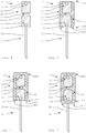
- FIGS. 2-7 show highly schematic representations of developments of the measuring module 15, in which the shaft portion 45 is shown in a sectional view.
- the measuring module 15 has a further measuring point 153.
- This measuring point 153 is arranged here on the puncturing section 35, so that an internal temperature of the food to be cooked 300 and preferably a core temperature can be detected. It is possible that the measuring system 5 also uses these temperature values to determine the state of the cooking. As a result, the control of the cooking process can be influenced even more targeted.
- the shank portion 45 of the measuring module 15 here comprises a gripping device 450 for the secure handling of the measuring module 15.
- the entire shank section 45 is designed here as a gripping device 450.
- the two measuring points 151, 152 are accommodated in the gripping device 450.
- As material for the gripping device 450 a material with a medium to high heat conduction is selected here.
- the shaft portion 45 and the grip device 450 therefore act in the manner of a bathleitides 65, so that the heat is well brought from the outside to the lying in the shaft portion 45 measuring points 151,152.
- the FIG. 3 shows an embodiment of the measuring module 15, in which the shaft portion 45 comprises a protective device 452.
- the protective device is provided here to prevent accidental touching of the puncturing section 35.
- the protector 452 is formed wider than the gripping device 450 so that accidental slippage from the gripping device 450 is effectively prevented.
- the measuring point 151 provided for detecting the surface temperature of the cooking product 300 is arranged in the protective device 452 here. This has the advantage that the measuring point 151 is arranged as close as possible to the puncturing section 35. Thus the measuring point 151 is positioned directly or at least very close to the food 300 when the measuring module 15 is inserted. However, it is also possible for the one measuring point 151 to be arranged outside the protective device 452 in the shaft section 45.
- the FIG. 4 shows a measuring module 15, in which between the measuring points 151,152 a thermal insulation device is arranged. 55.
- a thermal insulation device is arranged. 55.
- the heat conduction, in particular on the shortest path between the measuring points 151,152 difficult, so that the temperature contrast at the two measuring points 151,152 in the shaft portion 45 of the measuring module 15 is improved.
- the heat conduction between the respective measuring points 151, 152 and the surface of the shaft section 45 is optimized.
- measuring module 15 has along the longitudinal sides 453 a thermal protective insulation 451.
- a thermal protective insulation 451 As a result, an improved and particularly secure grip of the gripping device 450 is achieved.
- no protective insulation 451 is provided here.
- the heat-conducting elements 65 are exposed on the broad sides 454 and in particular have contact with the environment.
- the temperature detection by the measuring points 151, 152 embedded in the heat-conducting element 65 is thus not or not significantly impaired by the protective insulation 451.
- the two measuring points 151, 152 are also thermally decoupled here by the insulating device 55.
- a measuring module 15 in which the protective insulation 451 also extends over one of the two broad sides 454.
- the broad side 454 lying adjacent to the puncturing section 35 has been recessed, so that the heat-conducting element 65 has direct contact with the surroundings.
- the protective insulation On the other hand, 451 on the broad side 454 of the gripping device 450, which is opposite the puncturing section 35, has the advantage that it is particularly comfortable to grip it in this area.
- Measuring module 15 shown has a grip device 450, which is equipped on the longitudinal sides 453 and also on the broad sides 454 with a protective insulation 451. This ensures a particularly safe and comfortable handling of the measuring module 15. It is possible that the measuring points 151, 152 are completely surrounded by the protective insulation 451. However, the measuring points 151, 152 preferably have at least partially a heat-conducting contact with the surface of the gripping device 450 or the surroundings. For example, at least one heat-conducting element 65 can be arranged between the respective measuring point 151, 152 and the surface of the gripping device 450.
Landscapes
- Engineering & Computer Science (AREA)
- Chemical & Material Sciences (AREA)
- Combustion & Propulsion (AREA)
- Mechanical Engineering (AREA)
- General Engineering & Computer Science (AREA)
- Electric Stoves And Ranges (AREA)
- Electric Ovens (AREA)
Abstract
Description
- Die vorliegende Erfindung betrifft ein Gargerätsystem und Verfahren zum Betreiben eines solchen. Das Gargerätsystem umfasst wenigstens ein Gargerät mit wenigstens einer Heizeinrichtung und mit wenigstens einem beheizbaren Garraum zur Behandlung von Gargut.
- Gargeräte sind häufig mit Automatikprogrammen ausgestattet, die die Zubereitung von Lebensmitteln erleichtern und das Ergebnis eines Garvorgangs verbessern sollen. Beispielsweise wählt der Benutzer ein Produkt, das er zubereiten möchte, aus einer Liste aus und muss anschließend nur noch den Garvorgang starten. Alle weiteren erforderlichen Einstellungen des Gargerätes können dann durch das Automatikprogramm vorgegeben sein, wie z. B. Betriebsart und Garraumtemperatur.
- Für ein optimales Garergebnis mit einem Automatikprogramm sind allerdings eine Steuerung des Garvorgangs und insbesondere eine gezielte Regelung der Garraumtemperatur notwendig, die wiederum eine möglichst genaue Kenntnis des Garzustands voraussetzen. Im Stand der Technik werden zum Beispiel Kerntemperaturfühler oder Feuchtesensoren verwendet, um Rückschlüsse auf den Garzustand eines Lebensmittels zu ziehen. Allerdings ist die bekannte Sensorik oft sehr teuer und störanfällig oder liefert für eine detaillierte Überwachung und Ermittlung des Garzustands häufig nicht ausreichend Informationen.
- Es ist daher die Aufgabe der vorliegenden Erfindung, die Ermittlung des Garzustands eines Garguts zu verbessern.
- Diese Aufgabe wird gelöst durch ein Gargerätsystem mit den Merkmalen des Anspruchs 1 und durch ein Verfahren zum Betreiben eines Gargerätsystems mit den Merkmalen des Anspruchs 16. Weitere Ausgestaltungen ergeben sich aus den Unteransprüchen und den Ausführungsbeispielen.
- Das erfindungsgemäße Gargerätsystem umfasst wenigstens ein Gargerät mit wenigstens einer Heizeinrichtung und mit wenigstens einem beheizbaren Garraum zur Behandlung von Gargut. Es ist wenigstens eine Steuereinrichtung zur Steuerung der Heizeinrichtung vorgesehen. Dabei umfasst das Gargerätsystem wenigstens ein Messsystem mit wenigstens einem Messmodul mit wenigstens zwei Messstellen. Das Messsystem ist dazu geeignet und ausgebildet, den Garzustand eines Garguts zu ermitteln. Das Messmodul mit den wenigstens zwei Messstellen ist dazu geeignet und ausgebildet, wenigstens eine charakteristische Größe für eine Temperatur zu erfassen. Das Messmodul ist dazu geeignet und ausgebildet, für einen bestimmungsgemäßen Gebrauch in einer vom Gargut abhängigen Messposition ausgerichtet zu werden. Das Messmodul ist dazu geeignet und ausgebildet, mit wenigstens einer Messstelle wenigstens eine charakteristische Größe für eine Oberflächentemperatur des Garguts zu erfassen. Das Messmodul ist zudem dazu geeignet und ausgebildet, wenigstens eine charakteristische Größe für eine Umgebungstemperatur des Garguts zu erfassen.
- Das erfindungsgemäße Gargerätsystem hat viele Vorteile. Ein erheblicher Vorteil ist, dass zur Ermittlung des Garzustands sowohl die Oberflächentemperatur als auch die Umgebungstemperatur des Garguts berücksichtigt werden. In Kenntnis dieser Temperaturen kann eine besonders aussagekräftige und zuverlässige Bestimmung des Garzustandes erfolgen. Beispielsweise ist die Oberflächentemperatur des Garguts ein zuverlässiger Parameter für das Maß einer Bräunung. Die Umgebungstemperatur ist beispielsweise besonders hilfreich, um zu bestimmen, ob die für den Garvorgang gewünschten Temperaturen am und/oder im Gargut vorliegen. Die Umgebungstemperatur ist zudem für die Bestimmung des Garzustands wesentlich zuverlässiger als beispielsweise eine Temperaturerfassung an der Garraumdecke, da die Umgebungstemperatur stärker vom Garvorgang abhängt. Besonders hilfreich kann die Umgebungstemperatur beispielsweise bei Niedrigtemperaturgarvorgängen herangezogen werden. Besonders vorteilhaft ist auch, dass die Temperaturerfassung mit einem Messmodul erfolgt, welches variabel zum Gargut ausgerichtet werden kann, sodass eine möglichst günstige Messposition eingenommen wird. Dadurch kann der Garzustand besonders gut und zuverlässig ermittelt werden.
- Die Ausrichtung des Messmoduls in einer vom Gargut abhängigen Messposition umfasst insbesondere eine Ausrichtung des Messmoduls in Abhängigkeit der Größe und/oder der Form des Garguts und/oder der Position des Garguts im Garraum. Das Messmodul ist vorzugsweise geeignet und ausgebildet, für einen bestimmungsgemäßen Gebrauch im und/oder am Gargut befestigt zu werden. Beispielsweise kann wenigstens ein Teil des Messmoduls in das Gargut eingestochen werden. Möglich ist auch, dass das Messmodul indirekt am Gargut befestigt wird, beispielsweise über eine am Gargut befestigte Befestigungseinrichtung.
- Das Messmodul ist insbesondere dazu geeignet und ausgebildet, variabel im Garraum ausgerichtet zu werden. Insbesondere ist das Messmodul im Garraum nicht ortsfest installiert. Vorzugsweise ist das Messmodul im Garraum frei positionierbar. Das Messsystem kann wenigstens eine Befestigungseinrichtung umfassen, welche dazu geeignet und ausgebildet ist, das Messmodul lösbar aufzunehmen und in einer variablen Position zum Gargut im Garraum befestigt zu werden. Beispielsweise wird die die Befestigungseinrichtung an einer Garraumwandung und/oder an einer Gargutträgeraufnahme und/oder an einem Gargutträger befestigt. Vorzugsweise ist das Messmodul als ein separates Zubehörmodul des Gargeräts ausgebildet.
- Vorzugsweise umfassen die Messstellen jeweils wenigstens einen Sensor. Beispielsweise kann ein solcher Sensor wenigstens ein Widerstandsthermometer und/oder wenigstens ein Thermoelement oder dergleichen umfassen. Möglich ist auch, dass an den Messstellen die Veränderung einer Resonanzfrequenz eines Schwingkreises in Abhängigkeit der Temperatur erfasst wird.
- Es ist möglich, dass das Gargerät wenigstens eine Sensoreinrichtung mit wenigstens einer dem Garraum zugeordneten Sensoreinheit zur Erfassung von Temperaturen im Garraum umfasst. Dabei ist die Steuereinrichtung dazu geeignet und ausgebildet, die Heizeinrichtung wenigstens zeitweise in Abhängigkeit der von der Sensoreinrichtung erfassten Temperatur zu steuern. Das Messsystem ist insbesondere dazu geeignet und ausgebildet, wenigstens zeitweise die von der Sensoreinrichtung erfassten Temperaturen zur Ermittlung des Garzustands heranzuziehen. Eine solche Ausgestaltung hat den Vorteil, dass bereits für das Gargerät vorgesehene Sensoren zur Überwachung des Garzustands eingesetzt werden, wie zum Beispiel Sensoren für die Temperaturregelung im Garraum. Das Messsystem kann dazu geeignet und ausgebildet sein, wenigstens zeitweise die mit der Sensoreinrichtung erfassten Temperaturen nicht zu berücksichtigen. Das Messsystem kann auch dazu geeignet und ausgebildet sein, die mit der Sensoreinrichtung erfassten Temperaturen gegenüber den mit dem Messmodul erfassten Temperaturen zu priorisieren bzw. unterzuordnen.
- In allen Ausgestaltungen ist es bevorzugt, dass das Messmodul drahtlos mit der dem Messsystem und/oder mit der Steuereinrichtung wirkverbunden ist. Das Messsystem kann auch wenigstens eine Auswerteeinrichtung zur Auswertung der vom Messmodul erfassten Daten umfassen. Das Messmodul ist dann vorzugsweise drahtlos mit der Auswerteeinrichtung verbunden. Die Auswerteeinrichtung kann wenigstens teilweise auch in die Steuereinrichtung integriert sein. Vorzugsweise ist eine passive Übertragungstechnik vorgesehen, z. B. umfasst das Messmodul wenigstens eine SAW-Antenne. Möglich ist auch eine wenigstens teilweise aktive Übertragungstechnik. Vorzugsweise ist das Messmodul dazu geeignet und ausgebildet, die Temperaturabhängigkeit der Resonanzfrequenz eines Schwingkreises zur Temperaturerfassung heranzuziehen. Eine solche Temperaturerfassung ist besonders zuverlässig und das Messmodul ist dabei zudem besonders langlebig und und wartungsarm.
- Für die drahtlose Übertragung kann vorgesehen sein, dass das Messmodul wenigstens teilweise automatisch von dem Messsystem erkannt und gekoppelt wird. Insbesondere ist dabei ein Einsatz mehrerer und/oder verschiedener Messmodule möglich. Das Messmodul kann aber auch durch ein Kabel mit dem Messsystem und/oder der Steuereinrichtung verbunden sein. Dabei ist möglich, dass die Kabelverbindung insbesondere werkzeuglos durch den Benutzer trennbar ist und vorzugsweise steckbar ausgebildet ist. Möglich ist aber auch eine fest installierte Kabelverbindung.
- Vorzugsweise ist die Steuereinrichtung dazu geeignet und ausgebildet, die Heizeinrichtung wenigstens zeitweise in Abhängigkeit von den an wenigstens einer der Messstellen des Messsystems ermittelten Temperaturen zu steuern. Die mit dem Messsystem erfassten Temperaturen können für eine solche Beeinflussung der Heizeinrichtung besonders vorteilhaft eingesetzt werden, da die Steuerung der Heizeinrichtung einen besonders wichtigen Einfluss auf das Garergebnis hat. Möglich ist auch, dass die Steuereinrichtung dazu geeignet und ausgebildet ist, in Abhängigkeit einer an wenigstens einer der Messstellen erfassten Temperatur wenigstens ein Signal auszugeben. Besonders bevorzugt ist die Steuereinrichtung dazu geeignet und ausgebildet, in Abhängigkeit von den an beiden Messstellen erfassten Temperaturen zu steuern. Das Messsystem ist insbesondere dazu geeignet und ausgebildet, anhand der der Oberflächentemperatur und der Umgebungstemperatur des Garguts den Garzustand des Garguts zu ermitteln. Die Steuereinrichtung ist dazu geeignet und ausgebildet, in Abhängigkeit des ermittelten Garzustands die die Heizeinrichtung wenigstens zeitweise zu steuern und/oder wenigstens ein Signal auszugeben.
- Die Steuereinrichtung ist insbesondere dazu geeignet und ausgebildet, in Abhängigkeit eines durch einen Benutzer vorgewählten Betriebsmodus festzulegen, welche der wenigstens zwei Messstellen für die Steuerung der Heizeinrichtung berücksichtigt werden. Möglich ist auch, dass die Steuereinrichtung dazu geeignet und ausgebildet ist, in Abhängigkeit des vorgewählten Betriebsmodus eine Priorisierung für die Berücksichtigung der zwei Messstellen festzulegen. Solche Ausgestaltungen sind besonders vorteilhaft, da es je nach Betriebsmodus sinnvoller sein kann, die Oberflächentemperatur oder die Umgebungstemperatur stärker zu berücksichtigen.
- Beispielsweise ist die Umgebungstemperatur des Garguts besonders gut zur Überwachung von Niedrigtemperaturgarverfahren einsetzbar. Die Oberflächentemperatur des Garguts ist beispielsweise besonders hilfreich bei der Überwachung von Bräunungsverfahren, wie zum Beispiel Grillen. Insbesondere ist die Steuereinrichtung dazu geeignet und ausgebildet, bei einem Betriebsmodus mit einem Niedrigtemperaturgarverfahren nur und/oder auch die andere Messstelle für die Umgebungstemperatur zu berücksichtigen. Insbesondere ist die Steuereinrichtung dazu geeignet und ausgebildet, bei einem Betriebsmodus mit einem Bräunungsgarverfahren nur und/oder auch die eine Messstelle für die Oberflächentemperatur zu berücksichtigen. Möglich ist auch eine insbesondere priorisierte Berücksichtigung wenigstens einer weiteren Messstelle.
- In einer Weiterbildung ist die Steuereinrichtung dazu geeignet und ausgebildet, die von der Sensoreinrichtung erfassten Temperaturen im Garraum wenigstens zeitweise für die Steuerung der Heizeinrichtung zu vernachlässigen. Insbesondere erfolgt eine Vernachlässigung der von der Sensoreinrichtung erfassten Temperaturen dann, wenn ein Betriebsmodus vorliegt, welcher die an den Messstellen des Messmoduls erfassten Temperaturen berücksichtigt. Beispielsweise kann bei einem Betriebsmodus mit einem Niedrigtemperaturgarverfahren die Steuerung der Heizeinrichtung ohne Berücksichtigung der von der Sensoreinrichtung erfassten Temperaturen erfolgen. Möglich ist auch, dass die von der Sensoreinrichtung erfassten Temperaturen dann vernachlässigt werden, wenn die Temperaturen im Garraum und/oder die an den Messstellen des Messmoduls erfassten Temperaturen bestimmte Schwellenwerte erreichen und/oder überschreiten.
- Besonders bevorzugt ist das Messmodul dazu geeignet und ausgebildet, die charakteristische Größe für die Oberflächentemperatur des Garguts außerhalb des Garguts zu erfassen. Eine solche Erfassung der Oberflächentemperatur von außerhalb des Garguts ist besonders zuverlässig und zudem unaufwendig möglich. Insbesondere wird die Oberflächentemperatur des Garguts in unmittelbarer Nähe der Oberfläche des Garguts von außerhalb des Garguts erfasst. Dabei kann eine Beabstandung zur Gargutoberfläche von einigen Millimetern und/oder einigen Zentimetern vorgesehen sein. Insbesondere beträgt der Abstand der Messstelle für die Oberflächentemperatur weniger als 10 cm und besonders bevorzugt weniger als 5 cm. Möglich ist auch, dass die Messstelle für die Oberflächentemperatur weniger als 2 cm zur Gargutoberfläche beabstandet ist. Es ist auch möglich, dass die Messstelle die Oberfläche des Garguts wenigstens teilweise berührt.
- Es kann aber auch vorgesehen sein, dass das Messmodul dazu geeignet und ausgebildet ist, die charakteristische Größe für die Oberflächentemperatur des Garguts von innerhalb des Garguts zu erfassen. Beispielsweise kann dazu wenigstens eine Messstelle in das Gargut eingebracht werden. Dabei ist das Messmodul insbesondere dazu geeignet und ausgebildet, anhand einer Innentemperatur des Garguts die Oberflächentemperatur wenigstens näherungsweise zu ermitteln.
- In allen Ausgestaltungen ist es bevorzugt, dass dass das Messmodul wenigstens einen Einstichabschnitt zum Einstechen in das Gargut aufweist. Bevorzugt ist auch, dass das Messmodul wenigstens einen zur Anordnung außerhalb des Garguts vorgesehenen Schaftabschnitt aufweist. Dabei ist das Messmodul insbesondere als ein Gargutthermometer ausgebildet. Bevorzugt kann das Messmodul zum Beispiel auch zur Überwachung der Kerntemperatur beim Braten eingesetzt werden.
- Der Einstichabschnitt umfasst beispielsweise einen Spieß und/oder eine Gabel oder ist als solches ausgebildet. Der Schaftabschnitt ist vorzugsweise wenigstens teilweise als eine Griffeinrichtung ausgebildet oder umfasst eine solche. Der Schaftabschnitt kann auch wenigstens eine Isoliereinrichtung zum Schutz vor Wärme aufweisen. Möglich ist auch wenigstens eine Schutzeinrichtung, die ein unbeabsichtigtes Berühren des Einstichabschnittes und/oder des Gargutes beim Hantieren verhindert. Das Messmodul kann auch nur eine Griffeinrichtung umfassen und seine äußere Gestalt im Wesentlichen aus einer solchen gebildet sein.
- Vorzugsweise ist wenigstens eine der wenigstens zwei Messstellen im Schaftabschnitt angeordnet. Besonders bevorzugt sind beide Messstellen im Schaftabschnitt angeordnet. Eine solche Anordnung der Messstellen eignet sich besonders gut zur Erfassung der Oberflächentemperatur und der Umgebungstemperatur. Es ist aber auch möglich, dass die eine Messstelle zur Erfassung der Oberflächentemperatur im Einstichabschnitt angeordnet ist. Vorzugsweise ist die Messstelle dann an jenem Ende des Einstichabschnitts angeordnet, an welchem sich der Schaftabschnitt anschließt.
- Die eine der wenigstens zwei Messstellen ist vorzugsweise in einem an den Einstichabschnitt angrenzenden Drittel des Schaftabschnitts angeordnet. Eine solche Anordnung in der Nähe des Einstichabschnitts ist besonders vorteilhaft für die Erfassung der Oberflächentemperatur, da diese Messstelle bei einem eingestochenen Messmodul besonders nah am Gargut liegt. Vorzugsweise ist die eine Messstelle direkt angrenzend an den Einstichabschnitt im Schaftabschnitt angeordnet. Möglich ist auch, dass die eine Messstelle in einem an den Einstichabschnitt angrenzenden Viertel oder Sechstel und insbesondere Achtel des Schaftabschnitts angeordnet ist. Möglich ist auch, dass die eine Messstelle in einer an den Einstichabschnitt angrenzenden Hälfte des Schaftabschnitts angeordnet ist.
- Besonders bevorzugt ist die andere der wenigstens zwei Messstellen in einem dem Einstichabschnitt gegenüberliegenden Drittel des Schaftabschnitts angeordnet. Eine solche Anordnung der anderen Messstelle hat den Vorteil, dass mit dieser Messstelle die Umgebungstemperatur des Garguts besonders gut erfasst werden kann, wenn der Einstichabschnitt in das Gargut eingestochen ist. Vorzugsweise ist die andere Messstelle an einem dem Einstichabschnitt gegenüberliegenden Ende des Schaftabschnitts angeordnet. Möglich ist auch, dass die andere Messstelle in einem dem Einstichabschnitt gegenüberliegenden Viertel oder Sechstel und insbesondere Achtel des Schaftabschnitts angeordnet ist.
- Es ist möglich und bevorzugt, dass wenigstens eine Messstelle durch wenigstens ein Wärmeleitelement an eine Außenfläche des Schaftabschnitts Wärme leitend angebunden ist. Vorzugsweise sind beide Messstellen durch das Wärmeleitelement an die Außenfläche des Schaftabschnitts angebunden. Eine solche Ausgestaltung ist besonders bei im Inneren des Messmoduls liegenden Messstellen von Vorteil, da das Reaktionsverhalten der Messstellen gegenüber Temperaturveränderungen optimiert wird. Vorzugsweise ist das Wärmeleitelement aus einem Werkstoff mit geeigneter Wärmeleitfähigkeit gefertigt.
- Es ist möglich, dass wenigstens eine weitere Messstelle an dem Messmodul vorgesehen ist. Insbesondere ist die weitere Messstelle dazu geeignet und ausgebildet, eine Innentemperatur des Garguts zu erfassen. Die weitere Messstelle ist insbesondere im Einstichabschnitt des Messmoduls angeordnet. So kann z. B. auch die Innentemperatur im Gargut zur Ermittlung des Garzustands herangezogen werden. Das Messsystem ist insbesondere dazu geeignet und ausgebildet, eine Priorisierung für das Heranziehen der einen und der anderen sowie der weiteren Messstelle einzustellen. Eine solche Priorisierung erfolgt insbesondere in Abhängigkeit eines eingestellten Betriebsmodus.
- In einer vorteilhaften Weiterbildung weist der Schaftabschnitt wenigstens eine Griffeinrichtung auf. Dabei ist wenigstens eine der wenigstens zwei Messstellen in der Griffeinrichtung angeordnet. Dabei kann die Messstelle auch wenigstens teilweise an der Griffeinrichtung sein. Vorzugsweise sind die eine und die andere Messstelle in der Griffeinrichtung angeordnet. Es ist möglich, dass dass die Griffeinrichtung sich nur über einen Abschnitt des Schaftabschnitts erstreckt. Der Schaftabschnitt kann neben der Griffeinrichtung noch weitere Abschnitte umfassen. Beispielsweise kann der Schaftabschnitt wenigstens eine Schutzeinrichtung umfassen, die ein unbeabsichtigtes Berühren des Einstichabschnittes und/oder des Gargutes beim Hantieren verhindert. Möglich ist auch, dass der Schaftabschnitt nur eine Griffeinrichtung umfasst und seine äußere Gestalt im Wesentlichen aus einer solchen gebildet ist.
- Vorzugsweise umfasst die Griffeinrichtung wenigstens eine zur sicheren Handhabung geeignete Schutzisolierung. Die Schutzisolierung ist insbesondere dazu geeignet und ausgebildet, auch nach einem längeren Verweilen des Messmoduls bei höheren Temperaturen im Garraum ein sicheres Anfassen mit bloßen Händen zu ermöglichen. Insbesondere ist die Schutzisolierung wenigstens entlang der Längsseiten der Griffeinrichtung angeordnet. Die Schutzisolierung kann entlang aller Längsseiten der Griffeinrichtung angeordnet sein. Möglich ist auch, dass die Schutzisolierung entlang gegenüberliegender Längsseiten der Griffeinrichtung angeordnet ist. Insbesondere ist die Griffeinrichtung im Wesentlichen vollständig und vorzugsweise vollständig mit der Schutzisolierung ummantelt. Dabei ist möglich, dass die Schutzisolierung wenigstens eine Ausnehmung aufweist, in welcher wenigstens eine der wenigstens zwei Messstellen angeordnet ist. Insbesondere weist die Schutzisolierung für jede Messstelle jeweils wenigstens eine Ausnehmung auf. Die Schutzisolierung kann die Messstellen auch überdecken.
- Die Schutzisolierung ist insbesondere entlang einer dem Einstichabschnitt gegenüberliegenden Breitseite der Griffeinrichtung angeordnet. Die Breitseite ist dabei insbesondere eine Seite, welche im Wesentlichen quer zur Längsseite der Griffeinrichtung verläuft. Möglich ist auch, dass die Schutzisolierung entlang einer an den Einstichabschnitt angrenzenden Breitseite der Griffeinrichtung angeordnet ist. Vorzugsweise ist die Schutzisolierung sowohl an der dem Einstichabschnitt gegenüberliegenden Breitseite als auch an der dem an den Einstichabschnitt angrenzenden Breitseite der Griffeinrichtung angeordnet. Die Schutzisolierung kann entlang aller Breitseiten der Griffeinrichtung angeordnet sein. Besonders bevorzugt ist die Schutzisolierung sowohl an den Breitseiten als auch an den Längsseiten der Griffeinrichtung angeordnet. Besonders bevorzugt erfolgt eine Schutzisolierung an den Breitseiten dann, wenn auch eine Schutzisolierung entlang der Längsseiten vorgesehen ist.
- In allen Ausgestaltungen ist es bevorzugt, dass zwischen der einen Messstelle und der anderen Messstelle wenigstens eine thermische Isoliereinrichtung angeordnet ist. Eine solche Isoliereinrichtung zwischen den Messstellen verbessert die Messcharakteristik in vorteilhafter Weise. Insbesondere wird durch die Isoliereinrichtung der Temperaturkontrast zwischen den Messstellen verstärkt. Dabei ist die Wärmeleitung zwischen den Messstellen durch die thermische Isoliereinrichtung erschwert. Bei einer Mehrzahl von Messstellen sind vorzugsweise die Messstellen im Schaftabschnitt jeweils durch eine Isoliereinrichtung getrennt. Vorzugsweise sind auch der Einstichabschnitt und der Schaftabschnitt durch wenigstens eine thermische Isoliereinrichtung getrennt.
- Das erfindungsgemäße Verfahren eignet sich zum Betreiben eines Gargerätsystems. Das Gargerätsystem umfasst dabei wenigstens ein Gargerät mit wenigstens einer Heizeinrichtung und mit wenigstens einem beheizbaren Garraum zur Behandlung von Gargut. Dabei wird mit wenigstens einem Messsystem mit wenigstens einem Messmodul ein Garzustand des Garguts ermittelt. Dazu wird das Messmodul in einer vom Gargut abhängigen Messposition ausgerichtet. Insbesondere wird das Messmodul variabel zum Gargut im Garraum ausgerichtet. Mit wenigstens einer Messstelle des Messmoduls wird wenigstens eine charakteristische Größe für eine Oberflächentemperatur des Garguts erfasst. Mit wenigstens einer anderen Messstelle des Messmoduls wird wenigstens eine charakteristische Größe für eine Umgebungstemperatur des Garguts erfasst.
- Das erfindungsgemäße Verfahren ermöglicht eine besonders zuverlässige und aussagekräftige Temperaturerfassung, sodass auch entsprechend genaue Aussagen über den Garzustand des Garguts möglich sind. Dadurch kann insbesondere die Steuerung von Automatikprogrammen und letztlich auch das Garergebnis erheblich verbessert werden. Das erfindungsgemäße Verfahren wird insbesondere mit dem zuvor beschriebenen Gargerätsystem durchgeführt.
- Weitere Vorteile und Merkmale der vorliegenden Erfindung ergeben sich aus den Ausführungsbeispielen, welche im Folgenden mit Bezug auf die beiliegenden Figuren erläutert werden.
- In den Figuren zeigen:
- Figur 1
- eine schematische Darstellung eines erfindungsgemäßen Gargerätsystems;
- Figur 2
- eine schematische Darstellung eines Messmoduls; und
- Figuren 3-7
- Weiterbildungen des Messmoduls.
- Die
Figur 1 zeigt ein erfindungsgemäßes Gargerätsystem ein 100 mit einem Gargerät 1 und einem Messmodul 15. Das Gargerätsystem 100 wird vorzugsweise nach dem erfindungsgemäßen Verfahren betrieben. Das Gargerät 1 umfasst einen Garraum 3, welcher durch eine Heizeinrichtung 2 beheizbar und durch eine Tür 102 verschließbar ist. Die hier dargestellte Heizeinrichtung 2 umfasst beispielhaft eine Oberhitzeheizquelle und eine Unterhitzeheizquelle. Vorzugsweise sind auch weitere Heizquellen vorgesehen, wie zum Beispiel ein Grillheizkörper und/oder eine Umluftheizquelle und/oder andere thermische Heizquellen. Möglich ist auch, dass die Heizeinrichtung 2 eine Mikrowellenquelle und/oder eine Dampfheizquelle aufweist. Das Gargerät 1 kann auch als ein Kombigerät ausgeführt sein, beispielsweise als ein Backofen mit Dampfgarfunktion und/oder Mikrowellenfunktion. - Das Gargerät 1 ist über eine Bedieneinrichtung 101 bedienbar. Über die Bedieneinrichtung 101 können beispielsweise verschiedene Betriebsarten, Betriebstemperaturen und vorzugsweise verschiedene Programmbetriebsarten und Automatikfunktionen eingestellt werden. Zudem ist die Bedieneinrichtung 101 auch mit einer Anzeigeeinrichtung ausgestattet, über die den Benutzer verschiedene Informationen und/oder Signale über den Betriebsablauf und Garvorgang angezeigt werden. Die Bedieneinrichtung 101 kann auch mit einer berührungsempfindlichen Oberfläche bzw. als ein sogenannter Touchscreen ausgebildet sein.
- Das Gargut 300 befindet sich hier auf einem als Gargutträger 301 ausgebildeten Zubehörteil 200. Der Gargutträger 301 ist beispielsweise ein Rost oder ein Backblech. Der Gargutträger 301 ist im Garraum 3 auf einer hier nicht gezeigten Gargutträgeraufnahme 23 aufgenommen.
- Eine Steuereinrichtung 6 dient zur Regelung bzw. Steuerung verschiedener Gerätefunktionen, z. B. zur Temperaturregelung und/oder für die Automatikfunktionen. Mittels der Steuereinrichtung 6 wird zum Beispiel die Heizleistung der Heizeinrichtung 2 so eingestellt, dass im Garraum 3 Temperaturen vorliegen, welche im Bereich einer geforderten Solltemperatur liegen. Zur Überwachung der Temperaturen im Garraum 3 kann eine Sensoreinrichtung 4 mit einer Sensoreinheit 14 vorgesehen sein. Die Sensoreinheit 14 ist hier beispielhaft an einer Garraumwandung im oberen Bereich des Garraums 3 angebracht und gestrichelt eingezeichnet.
- Das Gargerätsystem 100 weist ein hier stark schematisiert dargestelltes Messsystem 5 auf. Das Messsystem 5 umfasst ein Messmodul 15 mit zwei Messstellen 151,152 sowie ein Auswertemodul 95 zur Auswertung der Messdaten. Das Messmodul 15 ist hier als Zubehörmodul 25 für das Gargerät 1 vorgesehen und drahtlos mit dem Auswertemodul 95 verbunden. Hier ist aufseiten des Messmoduls 15 eine passive Übertragungstechnik bevorzugt. Möglich ist auch eine aktive Übertragungstechnik. Es kann auch eine Anbindung des Messmoduls 15 per Kabel erfolgen. Das Auswertemodul 95 ist hier in der Steuereinrichtung 6 des Gargerätes 1 untergebracht. An den Messstellen 151, 152 des Messsystems 5 sind charakteristische Größen für Temperaturen erfassbar, die durch das Auswertemodul 95 ausgewertet und zur Ermittlung des Garzustands des Garguts 300 herangezogen werden.
- Das hier gezeigte Messmodul 15 erfasst mit einer ersten Messstelle 151 wenigstens eine charakteristische Größe für eine Oberflächentemperatur des Garguts. Mit einer anderen Messstelle 152 erfasst das Messmodul 15 wenigstens eine charakteristische Größe für eine Umgebungstemperatur des Garguts 300. Dazu umfassen die Messstellen 151,152 jeweils wenigstens einen Temperatursensor. Beispielsweise kann ein Widerstandsthermometer eingesetzt werden. Möglich ist auch, dass an den Messstellen 151,152 die Temperatur dadurch erfasst wird, dass die Veränderung einer Resonanzfrequenz eines Schwingkreises in Abhängigkeit der Temperatur registriert wird. Möglich sind auch andere geeignete Sensoren zur Temperaturerfassung, wie zum Beispiel Thermoelemente.
- Für einen bestimmungsgemäßen Einsatz wird das Messmodul 15 in einer vom Gargut 300 abhängigen Messposition ausgerichtet. Dazu ist das Messmodul 15 hier mit einem Einstichabschnitt 35 versehen, welcher als Spieß 350 ausgebildet ist. So ist ein besonders einfaches Einstechen in das Gargut 300 möglich. Die Messstellen 151,152 sind hier in einem Schaftabschnitt 45 des Messmoduls 15 angeordnet. Der Schaftabschnitt 45 verbleibt bei eingestochene Messmodul 15 außerhalb des Garguts 300. Durch die hier gezeigte Anordnung der beiden Messstellen 151,152 an den beiden jeweiligen Enden des Schaftabschnitts 45 wird eine vorteilhafte Beabstandung der Messstellen 151,152 erreicht.
- Zur Erfassung der Umgebungstemperatur des Garguts 300 ist die andere Messstelle 152 hier an dem oberen Ende des Schaftabschnitts 45 angeordnet. Die Anordnung der anderen Messstelle 152 am gegenüberliegenden Ende des Schaftabschnitts 45 ist besonders vorteilhaft für Erfassung der Umgebungstemperatur, da die Messstelle 152 auch bei vollständig eingestochene Einstichabschnitt 35 einen ausreichenden Abstand zur Oberfläche des Garguts 300 aufweist. So gewährleistet die Beabstandung der beiden Messstellen 151,152, dass die an den jeweiligen Messstellen 151,152 vorherrschen den Bedingungen sich nicht ungünstig gegenseitig beeinflussen.
- Die eine Messstelle 151 ist hingegen hier an dem unteren Ende des Schaftabschnitts 45 positioniert, welches sich an den Einstichabschnitt 35 anschließt. Dadurch liegt die eine Messstelle 151 bei eingestochene Messmodul 15 im Wesentlichen direkt benachbart oder zumindest sehr nahe an der Oberfläche des Garguts 300. Dadurch kann gewährleistet werden, dass die an der einen Messstelle 151 erfasste Temperatur im Wesentlichen durch die Oberflächentemperatur des Garguts 300 bestimmt ist. Der Einstichabschnitt 35 wird dabei möglichst tief und vorzugsweise vollständig in das Gargut 300 eingesteckt.
- Die an den Messstellen 151,152 erfassten Temperaturen können in vielfältiger Weise durch das Messsystem 5 ausgewertet und zur Gerätesteuerung eingesetzt werden.
- Beispielsweise kann die Oberflächentemperatur für eine gezielte Befeuchtung der Garraumatmosphäre während eines Garvorgangs herangezogen werden. Durch die Anpassung des Feuchtegehaltes der Garraumatmosphäre unter Berücksichtigung der Oberflächentemperatur des Garguts kann das Garergebnis besonders wirkungsvoll verbessert werden. So kann beispielsweise genau dann der Feuchtegehalt erhöht werden, wenn die Oberflächentemperatur auf ein bevorstehendes Austrocknen der Gargutoberfläche hinweist. So wird einerseits ein Austrocknen gezielt verhindert und andererseits eine zu hohe Feuchtigkeit der Gargutoberfläche vermieden. Besonders bevorzugt ist auch, dass der minimale Feuchtegehalt der Garraumatmosphäre in Abhängigkeit der Oberflächentemperatur des Garguts festgelegt wird. Zudem kann der Feuchtegehalt durch die Kenntnis der Oberflächentemperatur des Garguts so eingestellt werden, dass ein Kondensieren der Feuchtigkeit am Gargut erzielt wird. So kann durch die Befeuchtung ein zusätzlicher Wärmeeintrag in das Gargut erfolgen.
- Die Umgebungstemperatur kann auch beispielsweise besonders gut zur Temperaturregelung im Garraum 3 eingesetzt werden. Dabei kann wenigstens zeitweise allein die an der Messstelle 152 erfasste Umgebungstemperatur zur Temperaturregelung im Garraum 3 herangezogen werden. Da diese Messstelle 152 in der Regel näher am Gargut 300 angeordnet ist, als beispielsweise die Sensoreinheit 14 der Sensoreinrichtung 4, ist somit eine Temperaturregelung möglich, welche sehr direkt auf die Veränderungen des Garguts 300 reagiert. Möglich ist auch, dass wenigstens zeitweise sowohl die Messstelle 152 für die Umgebungstemperatur als auch die Sensoreinheit 14 an der Garraumwand zusammen zur Temperaturregelung herangezogen werden. Dabei kann die Temperaturregelung anhand eines Rechenwerts erfolgen, welcher sich aus den an der Messstelle 152 und der Sensoreinheit 14 registrierten Messwerten unter Berücksichtigung wenigstens einer empirischen Formel ergibt, beispielsweise eine Art gewichteter Mittelung. Die dahinter stehende Formel kann auch so realisiert sein, dass sie zum Beispiel je nach Betriebsart, Garraumtemperatur oder Automatikprogramm leichter oder stärker modifiziert ist.
- Besonders vorteilhaft kann die Umgebungstemperatur auch beim Niedrigtemperaturgaren herangezogen werden, da hierbei eine Temperaturregelung in der Nähe des Lebensmittels besonders entscheidend ist. Beispielsweise führen zehn Kelvin mehr oder weniger schnell zu Garzeitunterschieden in der Größenordnung von Stunden. Ein weiterer Vorteil der Erfassung der Umgebungstemperatur ist, dass in der Regel ohne Offset-Tabellen-Korrektur gearbeitet werden kann. Bei typischen Temperaturregelungen mit einem Temperatursensor 14 im Garraum 3 wird in der Regel eine geeignete Offsettabelle herangezogen.
- Die
Figuren 2-7 zeigen stark schematisierte Darstellungen von Weiterbildungen des Messmoduls 15, bei denen der Schaftabschnitt 45 in einer geschnittenen Ansicht abgebildet ist. - In der
Figur 2 weist das Messmodul 15 eine weitere Messstelle 153 auf. Diese Messstelle 153 ist hier am Einstichabschnitt 35 angeordnet, sodass eine Innentemperatur des Garguts 300 und vorzugsweise eine Kerntemperatur erfassbar ist. Dabei ist möglich, dass das Messsystem 5 auch diese Temperaturwerte zur Ermittlung des Garzustands heranzieht. Dadurch kann die Steuerung des Garvorgangs noch gezielter beeinflusst werden. - Der Schaftabschnitt 45 des Messmoduls 15 umfasst hier eine Griffeinrichtung 450 zur sicheren Handhabung des Messmoduls 15. Dabei ist der gesamte Schaftabschnitt 45 hier als Griffeinrichtung 450 ausgebildet. Die beiden Messstellen 151,152 sind in der Griffeinrichtung 450 untergebracht. Als Werkstoff für die Griffeinrichtung 450 ist hier ein Material mit einer mittleren bis hohen Wärmeleitung gewählt. Der Schaftabschnitt 45 bzw. die Griffeinrichtung 450 wirken daher in der Art eines Wärmeleitelementes 65, sodass die Wärme von außen gut an die im Schaftabschnitt 45 liegenden Messstellen 151,152 herangeführt wird.
- Die
Figur 3 zeigt eine Ausgestaltung des Messmoduls 15, bei der der Schaftabschnitt 45 eine Schutzeinrichtung 452 umfasst. Die Schutzeinrichtung ist hier dazu vorgesehen, ein versehentliches Anfassen des Einstichabschnitts 35 zu verhindern. Die Schutzeinrichtung 452 ist überstehend bzw. breiter als die Griffeinrichtung 450 ausgebildet, sodass ein versehentliches Abrutschen von der Griffeinrichtung 450 wirkungsvoll verhindert wird. Zudem ist hier die eine zur Erfassung der Oberflächentemperatur des Garguts 300 vorgesehene Messstelle 151 in der Schutzeinrichtung 452 angeordnet. Das hat den Vorteil, dass die Messstelle 151 möglichst nah am Einstichabschnitt 35 angeordnet ist. So wird die Messstelle 151 bei eingestochene Messmodul 15 direkt oder wenigstens sehr nahe am Gargut 300 positioniert. Möglich ist aber auch, dass die eine Messstelle 151 außerhalb der Schutzeinrichtung 452 im Schaftabschnitt 45 angeordnet ist. - Die
Figur 4 zeigt ein Messmodul 15, bei welchem zwischen den Messstellen 151,152 eine thermische Isoliereinrichtung angeordnet ist. 55. Durch die Isoliereinrichtung 55 ist die Wärmeleitung insbesondere auf dem kürzesten Weg zwischen den Messstellen 151,152 erschwert, sodass der Temperaturkontrast an den zwei Messstellen 151,152 im Schaftabschnitt 45 des Messmoduls 15 verbessert wird. Durch die Einbettung der Messstellen 151,152 in jeweils ein Wärmeleitelement 65 ist die Wärmeleitung zwischen den jeweiligen Messstellen 151,152 und der Oberfläche des Schaftabschnitts 45 hingegen optimiert. - Das in der
Figur 5 gezeigte Messmodul 15 weist entlang der Längsseiten 453 eine thermische Schutzisolierung 451 auf. Dadurch wird ein verbessertes und besonders sicheres Anfassen der Griffeinrichtung 450 erreicht. Entlang der Breitseiten 454 des Schaftabschnitts 45 ist hier keine Schutzisolierung 451 vorgesehen. Dadurch liegen an den Breitseiten 454 die Wärmeleitelemente 65 frei und haben insbesondere Kontakt zur Umgebung. Die Temperaturerfassung durch die in den Wärmeleitelement 65 eingebetteten Messstellen 151,152 wird so durch die Schutzisolierung 451 nicht bzw. nicht wesentlich beeinträchtigt. Die beiden Messstellen 151,152 sind auch hier durch die Isoliereinrichtung 55 thermisch entkoppelt. - In der
Figur 6 ist ein Messmodul 15 gezeigt, bei welchem sich die Schutzisolierung 451 auch über eine der beiden Breitseiten 454 erstreckt. Dabei wurde hier die benachbart zum Einstichabschnitt 35 liegende Breitseite 454 ausgespart, sodass das Wärmeleitelement 65 direkten Kontakt zur Umgebung hat. Das ist besonders vorteilhaft zur Erfassung der Oberflächentemperatur, da das Wärmeleitelement 65 bei eingestochene Messmodul 15 direkten Kontakt zur Gargutoberfläche bekommt oder zumindest sehr nahe an dieser angeordnet ist. Die Schutzisolierung 451 an der dem Einstichabschnitt 35 gegenüberliegenden Breitseite 454 der Griffeinrichtung 450 hat dagegen den Vorteil, dass in diesem Bereich ein Anfassen besonders komfortabel gestaltet ist. - Das in der
Figur 7 gezeigte Messmodul 15 weist eine Griffeinrichtung 450 auf, welche an den Längsseiten 453 und auch an den Breitseiten 454 mit einer Schutzisolierung 451 ausgestattet ist. Dadurch ist ein besonders sicherer und komfortabler Umgang mit dem Messmodul 15 gewährleistet. Dabei ist es möglich, dass die Messstellen 151,152 vollständig von der Schutzisolierung 451 umgeben sind. Vorzugsweise weisen die Messstellen 151,152 jedoch wenigstens teilweise einen Wärme leitenden Kontakt zur Oberfläche der Griffeinrichtung 450 bzw. der Umgebung auf. Beispielsweise kann dazu zwischen der jeweiligen Messstelle 151,152 und der Oberfläche der Griffeinrichtung 450 wenigstens ein Wärmeleitelement 65 angeordnet sein. -
- 1
- Gargerät
- 2
- Heizeinrichtung
- 3
- Garraum
- 4
- Sensoreinrichtung
- 5
- Messsystem
- 6
- Steuereinrichtung
- 14
- Sensoreinheit
- 15
- Messmodul
- 23
- Gargutträgeraufnahme
- 25
- Zubehörmodul
- 35
- Einstichabschnitt
- 45
- Schaftabschnitt
- 55
- Isoliereinrichtung
- 65
- Wärmeleitelement
- 95
- Auswertemodul
- 100
- Gargerätsystem
- 101
- Bedieneinrichtung
- 102
- Tür
- 103
- Griff
- 151
- Messstelle
- 152
- Messstelle
- 153
- Messstelle
- 200
- Zubehörteil
- 300
- Gargut
- 301
- Gargutträger
- 350
- Spieß
- 450
- Griffeinrichtung
- 451
- Schutzisolierung
- 452
- Schutzeinrichtung
- 453
- Längsseite
- 454
- Breitseite
Claims (16)
- Gargerätsystem (100) umfassend wenigstens ein Gargerät (1) mit wenigstens einer Heizeinrichtung (2) und mit wenigstens einem beheizbaren Garraum (3) zur Behandlung von Gargut (300) und mit wenigstens einer Steuereinrichtung (6) zur Steuerung der Heizeinrichtung (2),
dadurch gekennzeichnet,
dass zur Ermittlung eines Garzustands des Garguts (300) wenigstens ein Messsystem (5) mit wenigstens einem Messmodul (15) mit wenigstens zwei Messstellen (151, 152) zur Temperaturerfassung umfasst ist und dass das Messmodul (15) dazu geeignet und ausgebildet ist, für einen bestimmungsgemäßen Gebrauch in einer vom Gargut (300) abhängigen Messposition ausgerichtet zu werden und mit wenigstens einer Messstelle (151) wenigstens eine charakteristische Größe für eine Oberflächentemperatur des Garguts (300) zu erfassen und mit wenigstens einer anderen Messstelle (152) wenigstens eine charakteristische Größe für eine Umgebungstemperatur des Garguts (300) zu erfassen. - Gargerätsystem (100) nach Anspruch 1, dadurch gekennzeichnet, dass die Steuereinrichtung (6) dazu geeignet und ausgebildet ist, die Heizeinrichtung (2) wenigstens zeitweise in Abhängigkeit von den an wenigstens einer der Messstellen (151, 152) ermittelten Temperaturen zu steuern und/oder wenigstens ein Signal auszugeben.
- Gargerätsystem (100) nach dem vorhergehenden Anspruch, dadurch gekennzeichnet, dass die Steuereinrichtung (6) dazu geeignet und ausgebildet ist, in Abhängigkeit eines durch einen Benutzer vorgewählten Betriebsmodus festzulegen, welche der wenigstens zwei Messstellen (151, 152) für die Steuerung der Heizeinrichtung (2) berücksichtigt werden.
- Gargerätsystem (100) nach einem der beiden vorhergehenden Ansprüche, dadurch gekennzeichnet, dass die Steuereinrichtung (6) dazu geeignet und ausgebildet ist, die von der Sensoreinrichtung (4) erfassten Temperaturen im Garraum (3) wenigstens zeitweise für die Steuerung der Heizeinrichtung (2) zu vernachlässigen.
- Gargerätsystem (100) nach einem der vorhergehenden Ansprüche, dadurch gekennzeichnet, dass das Messmodul (15) dazu geeignet und ausgebildet ist, die charakteristische Größe für die Oberflächentemperatur des Garguts (300) von außerhalb des Garguts (300) zu erfassen.
- Gargerätsystem (100) nach einem der vorhergehenden Ansprüche, dadurch gekennzeichnet, dass das Messmodul (15) wenigstens einen Einstichabschnitt (35) zum Einstechen in das Gargut (300) und wenigstens einen zur Anordnung außerhalb des Garguts (300) vorgesehenen Schaftabschnitt (45) aufweist.
- Gargerätsystem (100) nach dem vorhergehenden Anspruch, dadurch gekennzeichnet, dass die eine Messstelle (151) und/oder die andere Messstelle (152) im Schaftabschnitt (45) angeordnet sind.
- Gargerätsystem (100) nach einem der beiden vorhergehenden Ansprüche, dadurch gekennzeichnet, dass die eine Messstelle (151) in einem an den Einstichabschnitt (35) angrenzenden Drittel des Schaftabschnitts (45) angeordnet ist.
- Gargerätsystem (100) nach einem der drei vorhergehenden Ansprüche, dadurch gekennzeichnet, dass die andere Messstelle (152) in einem dem Einstichabschnitt (35) gegenüberliegenden Drittel des Schaftabschnitts (45) angeordnet ist.
- Gargerätsystem (100) nach einem der Ansprüche 6 bis 9, dadurch gekennzeichnet, dass wenigstens eine Messstelle (151, 152) durch wenigstens ein Wärmeleitelement (65) an eine Außenfläche des Schaftabschnitts (45) Wärme leitend angebunden ist.
- Gargerätsystem (100) nach einem der Ansprüche 6 bis 10, dadurch gekennzeichnet, dass wenigstens eine weitere Messstelle (153) zur Erfassung einer Innentemperatur des Garguts (300) im Einstichabschnitt (35) angeordnet ist.
- Gargerätsystem (100) nach einem der Ansprüche 6 bis 11, dadurch gekennzeichnet, dass der Schaftabschnitt (45) wenigstens eine Griffeinrichtung (450) aufweist und dass die eine Messstelle (151) und/oder die andere Messstelle (152) in der Griffeinrichtung (450) angeordnet sind.
- Gargerätsystem (100) nach dem vorhergehenden Anspruch, dadurch gekennzeichnet, dass die Griffeinrichtung (450) wenigstens eine zur sicheren Handhabung geeignete Schutzisolierung (451) umfasst und dass die Schutzisolierung (451) wenigstens entlang der Längsseiten der Griffeinrichtung (450) angeordnet ist.
- Gargerätsystem (100) nach dem vorhergehenden Anspruch, dadurch gekennzeichnet, dass die Schutzisolierung (451) entlang einer dem Einstichabschnitt (35) gegenüberliegenden Breitseite der Griffeinrichtung (450) angeordnet ist und/oder dass die Schutzisolierung (451) entlang einer an den Einstichabschnitt (35) angrenzenden Breitseite der Griffeinrichtung (450) angeordnet ist.
- Gargerätsystem (100) nach einem der vorhergehenden Ansprüche, dadurch gekennzeichnet, dass zwischen der einen Messstelle (151) und der anderen Messstelle (152) wenigstens eine thermische Isoliereinrichtung (55) angeordnet ist.
- Verfahren zum Betreiben eines Gargerätsystems (100) mit wenigstens einem Gargerät (1) mit wenigstens einer Heizeinrichtung (2) und mit wenigstens einem beheizbaren Garraum (3) zur Behandlung von Gargut (300),
dadurch gekennzeichnet,
dass mit wenigstens einem Messsystem (5) mit wenigstens einem Messmodul (15) ein Garzustand des Garguts (300) ermittelt wird und dass das Messmodul (15) dazu in einer vom Gargut (300) abhängigen Messposition ausgerichtet wird und dass mit wenigstens einer Messstelle (151) des Messmoduls (15) wenigstens eine charakteristische Größe für eine Oberflächentemperatur des Garguts (300) erfasst wird und dass mit wenigstens einer anderen Messstelle (152) des Messmoduls (15) wenigstens eine charakteristische Größe für eine Umgebungstemperatur des Garguts (300) erfasst wird.
Applications Claiming Priority (1)
| Application Number | Priority Date | Filing Date | Title |
|---|---|---|---|
| DE102016102249.7A DE102016102249A1 (de) | 2016-02-10 | 2016-02-10 | Gargerätsystem und Verfahren zum Betreiben |
Publications (2)
| Publication Number | Publication Date |
|---|---|
| EP3205942A2 true EP3205942A2 (de) | 2017-08-16 |
| EP3205942A3 EP3205942A3 (de) | 2017-11-15 |
Family
ID=57794149
Family Applications (1)
| Application Number | Title | Priority Date | Filing Date |
|---|---|---|---|
| EP17150939.1A Withdrawn EP3205942A3 (de) | 2016-02-10 | 2017-01-11 | Gargerätsystem und verfahren zum betreiben |
Country Status (2)
| Country | Link |
|---|---|
| EP (1) | EP3205942A3 (de) |
| DE (1) | DE102016102249A1 (de) |
Cited By (1)
| Publication number | Priority date | Publication date | Assignee | Title |
|---|---|---|---|---|
| CN115615570A (zh) * | 2021-07-13 | 2023-01-17 | 德国福维克控股公司 | 用于制备食物的食物温度计、系统和方法 |
Family Cites Families (5)
| Publication number | Priority date | Publication date | Assignee | Title |
|---|---|---|---|---|
| DE10306940A1 (de) * | 2003-02-18 | 2004-09-09 | Rational Ag | Verfahren zum Steuern eines Backprozesses |
| DE202005017251U1 (de) * | 2005-11-04 | 2007-03-15 | Sinnotec Entwicklungsgesellschaft Ltd. | Garprozessfühler |
| DE102005057884A1 (de) * | 2005-12-02 | 2007-06-06 | Rational Ag | Verfahren zum Führen eines Garprozesses mit einem Mehrpunkttemperatursensor |
| EP1921384B1 (de) * | 2006-11-02 | 2009-05-27 | Electrolux Home Products Corporation N.V. | Vorrichtung und Verfahren zum Bestimmen der Temperatur im Inneren eines Garguts |
| DE102007057107A1 (de) * | 2007-11-26 | 2009-06-10 | Rational Ag | Verfahren zur Bestimmung der Kerntemperatur eines Garguts und Gargerät zur Durchführung solch eines Verfahrens |
-
2016
- 2016-02-10 DE DE102016102249.7A patent/DE102016102249A1/de not_active Withdrawn
-
2017
- 2017-01-11 EP EP17150939.1A patent/EP3205942A3/de not_active Withdrawn
Non-Patent Citations (1)
| Title |
|---|
| None |
Cited By (1)
| Publication number | Priority date | Publication date | Assignee | Title |
|---|---|---|---|---|
| CN115615570A (zh) * | 2021-07-13 | 2023-01-17 | 德国福维克控股公司 | 用于制备食物的食物温度计、系统和方法 |
Also Published As
| Publication number | Publication date |
|---|---|
| DE102016102249A1 (de) | 2017-08-10 |
| EP3205942A3 (de) | 2017-11-15 |
Similar Documents
| Publication | Publication Date | Title |
|---|---|---|
| EP2063183B1 (de) | Verfahren zur Bestimmung der Kerntemperatur eines Garguts | |
| DE10327861B4 (de) | Verfahren zur Steuerung eines Garvorgangs bei einem Gargerät und Gargerät | |
| DE102016102260A1 (de) | Verfahren zum Betreiben eines Gargerätsystems und Gargerätsystem | |
| EP2661944A2 (de) | Induktionskochgerät zum temperaturgesteuerten kochen | |
| AU2017347919B2 (en) | Electronic temperature control system for a grill | |
| EP2590473B1 (de) | Gargerätevorrichtung | |
| DE102016102245A1 (de) | Gargerät und Verfahren zum Betreiben | |
| DE102006058617B3 (de) | Verfahren zur Bestimmung des zeitlichen Verlaufs der während eines Garvorgangs in einem Garraum eines Backofens von einem Gargut abgegebenen Dampfmenge sowie Vorrichtung zur Durchführung des Verfahrens | |
| DE102009019613A1 (de) | Temperaturmesseinrichtung für ein Gargut | |
| DE102019107834A1 (de) | Verfahren zum Betreiben eines Gargeräts und Gargerät | |
| EP3560281B1 (de) | Gargerätevorrichtung | |
| DE102019107846A1 (de) | Verfahren zum Betreiben eines Gargeräts und Gargerät | |
| EP2163823B1 (de) | Garprozessfühler für ein Gargerät | |
| DE102016102249A1 (de) | Gargerätsystem und Verfahren zum Betreiben | |
| DE102014103480B4 (de) | Gargerät und Verfahren zum Betreiben eines Gargerätes | |
| DE102005023468A1 (de) | Gargerät mit Temperaturerfassungsvorrichtung | |
| EP2469174A2 (de) | Gargerät | |
| EP3258742A1 (de) | Verfahren zum betreiben eines gargerätes und gargerät | |
| WO2015018891A1 (de) | Kocheinrichtung und verfahren zum betreiben der kocheinrichtung | |
| DE102019119071A1 (de) | Verfahren zum Betreiben eines Geräts, insbesondere Gargerät oder Trocknungsgerät, und Gerät | |
| DE102004033454A1 (de) | Kochgerät mit Temperaturerfassung und Verfahren zur Temperaturerfassung an einem Kochgerät | |
| DE102017114987B3 (de) | Messsonde und Gargerät mit einer solchen Messsonde | |
| DE102015212778A1 (de) | Abnehmbarer Kochsensor | |
| EP1731000B1 (de) | Häuslicher ofen und diesen verwendender kochprozess | |
| EP3031298A1 (de) | Kocheinrichtung und verfahren zum betreiben einer kocheinrichtung |
Legal Events
| Date | Code | Title | Description |
|---|---|---|---|
| PUAI | Public reference made under article 153(3) epc to a published international application that has entered the european phase |
Free format text: ORIGINAL CODE: 0009012 |
|
| AK | Designated contracting states |
Kind code of ref document: A2 Designated state(s): AL AT BE BG CH CY CZ DE DK EE ES FI FR GB GR HR HU IE IS IT LI LT LU LV MC MK MT NL NO PL PT RO RS SE SI SK SM TR |
|
| AX | Request for extension of the european patent |
Extension state: BA ME |
|
| PUAL | Search report despatched |
Free format text: ORIGINAL CODE: 0009013 |
|
| RIC1 | Information provided on ipc code assigned before grant |
Ipc: F24C 7/08 20060101AFI20170915BHEP |
|
| AK | Designated contracting states |
Kind code of ref document: A3 Designated state(s): AL AT BE BG CH CY CZ DE DK EE ES FI FR GB GR HR HU IE IS IT LI LT LU LV MC MK MT NL NO PL PT RO RS SE SI SK SM TR |
|
| AX | Request for extension of the european patent |
Extension state: BA ME |
|
| RIC1 | Information provided on ipc code assigned before grant |
Ipc: F24C 7/08 20060101AFI20171012BHEP |
|
| STAA | Information on the status of an ep patent application or granted ep patent |
Free format text: STATUS: THE APPLICATION IS DEEMED TO BE WITHDRAWN |
|
| 18D | Application deemed to be withdrawn |
Effective date: 20180516 |