EP3205934A1 - Heizgerät mit luftansauggehäuse aus schaummaterial - Google Patents
Heizgerät mit luftansauggehäuse aus schaummaterial Download PDFInfo
- Publication number
- EP3205934A1 EP3205934A1 EP17154546.0A EP17154546A EP3205934A1 EP 3205934 A1 EP3205934 A1 EP 3205934A1 EP 17154546 A EP17154546 A EP 17154546A EP 3205934 A1 EP3205934 A1 EP 3205934A1
- Authority
- EP
- European Patent Office
- Prior art keywords
- intake system
- air
- heater
- outer housing
- cavity
- Prior art date
- Legal status (The legal status is an assumption and is not a legal conclusion. Google has not performed a legal analysis and makes no representation as to the accuracy of the status listed.)
- Granted
Links
Images

Classifications
-
- F—MECHANICAL ENGINEERING; LIGHTING; HEATING; WEAPONS; BLASTING
- F23—COMBUSTION APPARATUS; COMBUSTION PROCESSES
- F23C—METHODS OR APPARATUS FOR COMBUSTION USING FLUID FUEL OR SOLID FUEL SUSPENDED IN A CARRIER GAS OR AIR
- F23C7/00—Combustion apparatus characterised by arrangements for air supply
- F23C7/008—Flow control devices
-
- F—MECHANICAL ENGINEERING; LIGHTING; HEATING; WEAPONS; BLASTING
- F23—COMBUSTION APPARATUS; COMBUSTION PROCESSES
- F23D—BURNERS
- F23D14/00—Burners for combustion of a gas, e.g. of a gas stored under pressure as a liquid
- F23D14/34—Burners specially adapted for use with means for pressurising the gaseous fuel or the combustion air
- F23D14/36—Burners specially adapted for use with means for pressurising the gaseous fuel or the combustion air in which the compressor and burner form a single unit
-
- F—MECHANICAL ENGINEERING; LIGHTING; HEATING; WEAPONS; BLASTING
- F23—COMBUSTION APPARATUS; COMBUSTION PROCESSES
- F23M—CASINGS, LININGS, WALLS OR DOORS SPECIALLY ADAPTED FOR COMBUSTION CHAMBERS, e.g. FIREBRIDGES; DEVICES FOR DEFLECTING AIR, FLAMES OR COMBUSTION PRODUCTS IN COMBUSTION CHAMBERS; SAFETY ARRANGEMENTS SPECIALLY ADAPTED FOR COMBUSTION APPARATUS; DETAILS OF COMBUSTION CHAMBERS, NOT OTHERWISE PROVIDED FOR
- F23M9/00—Baffles or deflectors for air or combustion products; Flame shields
- F23M9/02—Baffles or deflectors for air or combustion products; Flame shields in air inlets
-
- F—MECHANICAL ENGINEERING; LIGHTING; HEATING; WEAPONS; BLASTING
- F23—COMBUSTION APPARATUS; COMBUSTION PROCESSES
- F23N—REGULATING OR CONTROLLING COMBUSTION
- F23N3/00—Regulating air supply or draught
- F23N3/007—Regulating air supply or draught using mechanical means
Definitions
- the invention relates to a heater for heating a heat transfer medium for heating a building or for providing hot water based on the combustion of a fuel.
- this intake pipe Like all fixed-size intake pipes, this intake pipe also has the disadvantage of exhibiting its best effect in a restricted range of operating parameters. Therefore, in each case sets of several intake pipes are usually kept ready for certain heaters, with which the intake system can be acoustically adjusted by replacing the intake pipe according to the boundary conditions. In addition, the intake pipe is basically to be provided as an additional component and increases the complexity and cost of the heater.
- the intake system has a split outer housing in which a cavity is provided.
- this cavity can be configured with air guide elements, a flow channel.
- the outer housing is made of foam material, preferably EPP.
- the air guiding elements are made of foam material, preferably of EPP.
- the intake system outer housing is integrally formed with a fixation for at least one unit of the heating system or connected with such a fixation, in the fixation of an assembly can be inserted in a form-fitting manner and thus fixed, without being screwed, for example, with the recording.
- a heater is described with insulating means in which the individual units of the heater are inserted so that the units are positively fixed by the insulating means.
- the intake system is formed directly by the insulating means, wherein the insulating means is the outer casing of the intake system, which encloses the cavity.
- the inserted units are at least the fuel gas-air mixing device and / or the fan for supplying the combustion air to the burner.
- the intake system is designed so that the heat loss of the pump is used to promote a heat transfer medium for preheating the combustion air by being passed past the pump and so absorbs the heat loss.
- the air guide elements can be positively inserted into the cavity, clamped non-positively or materially connected by gluing or welding.
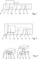
- FIG. 1 represents an inventive extraction system with open and FIG. 2 with closed outer housing.
- the suction system consists of a suction system outer housing 7, which is made in two parts and is divided by a parting line 14.
- the exhaust system outer housing 7 has a cavity 9, which forms a flow channel 8.
- the flow channel 8 is not completely provided in the parting plane. According to the invention it is sufficient if a part of the cavity 9 is located in the parting plane in order there to air guiding elements 15 (in FIG. 3 shown) to bring.
- the fuel gas-air mixing device 4 and the blower 3 are fixed.
- the intake system outer housing 7 fixings 16, for example in the form of pockets, recesses or holders, in which the units are fixed in a form-fitting manner.
- the intake system outer housing 7 must sealingly surround the fuel gas / air mixing device 4 in the region of the air inlet, in order to ensure an exclusive air flow through the cavity 9 or the flow channel 8.
- FIGS. 3 to 5 how according to the invention in the cavity 9 of the intake system outer housing 7 of the flow channel 8 is formed.
- the intake system outer housing 7 provides receptacles 10 with which the air guiding elements 15 can be fastened in the cavity 9.
- This can, as in the example in FIG. 3 shown, form-fitting. It is also possible to frictionally clamp the air guide elements 15 between the housing halves of the intake system outer housing 7 or to join them by adhesive bonding or welding.
- FIGS. 4 and 5 show two variants in which with air guide elements 15 in the cavity 9, a flow channel 8 is formed. The illustration corresponds to a plan view of FIG FIG. 1 shown variant. Between the housing halves of the intake system outer housing, a G-shaped cavity 9 is formed.
- a short flow channel 8 is formed.
- air guide elements 15 a meandering flow channel 8, which is longer.
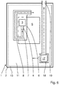
- FIG. 6 represents a heater according to the invention with the intake system 6 according to the invention.
- this heater units such as the burner 5 and the pump 17, with a heated by the burner 5 heat transfer medium is circulated, fixed in form-locking fixations of the insulation 11.
- heat transfer medium is circulated, fixed in form-locking fixations of the insulation 11.
- FIG. 1 directed.
- blower-assisted heaters have a vacuum chamber which is formed by the fact that the outside air is not supplied directly to the blower 3, but is first conducted into the interior of the housing and is then sucked in by the blower 3. Thereby, a negative pressure in the entire housing 2 of the heater 1 is ensured, so that no gas can escape from the heater 1 to the outside.
- the air is passed through an air supply 19 through a channel in the insulation 11 into the heater 1 enclosed by the housing 2.
- the air flows through channels 18, the pump 17 and absorbs their heat loss.
- the air flows due to the through the Blower 3 produced pressure gradient through the flow channel 8 in the intake system outer housing in the manner described above by the fuel gas-air mixing device 4, where it is mixed with fuel gas, and by the blower 3 in the burner 5.
- the intake system outer housing 7 be integral with the insulation 11, be directly connected to this or be indirectly connected via brackets with this.
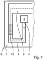
- FIG. 7 put that in FIG. 4 described intake system in which an additional damper 12 is provided.
- This damper 12 may be made of a porous material, a flow or a sintered body.
- the occurrence of self-excited vibrations in the intake system 6 is damped by the damper 12.
Landscapes
- Engineering & Computer Science (AREA)
- Chemical & Material Sciences (AREA)
- Combustion & Propulsion (AREA)
- Mechanical Engineering (AREA)
- General Engineering & Computer Science (AREA)
- Direct Air Heating By Heater Or Combustion Gas (AREA)
- Housings, Intake/Discharge, And Installation Of Fluid Heaters (AREA)
Abstract
Description
- Die Erfindung betrifft ein Heizgerät zum Erwärmen eines Wärmeträgermediums zur Beheizung eines Gebäudes oder zum Bereitstellen von Warmwasser auf Basis der Verbrennung eines Brennstoffs.
- Aus der Patentanmeldung
DE 10 2006 036 471 A1 ist ein gattungsgemäßes Heizgerät mit einem ein Ansaugrohr umfassenden Ansaugsystem stromauf des Verbrennungsluft-Gebläses bekannt. Ansaugrohre sind grundsätzlich bekannt, um das Verbrennungssystem akustisch zu verstimmen und so die Schallemissionen zu senken. Es wird vorgeschlagen, die Wirkung des Ansaugrohrs zu verbessern durch Einbringen von scharfkantigen Umlenkungen, Bohrungen und elastische Materialien in das Ansaugrohr. - Wie alle Ansaugrohre fester Dimensionen hat auch dieses Ansaugrohr den Nachteil, dass es seine beste Wirkung in einem eingeschränkten Betriebsparameter-Bereich entfaltet. Daher werden in der Regel für bestimmte Heizgeräte jeweils Sätze von mehreren Ansaugrohren bereitgehalten, mit denen das Ansaugsystem durch Austausch des Ansaugrohrs entsprechend den Randbedingungen akustisch angepasst werden kann. Zudem ist das Ansaugrohr grundsätzlich als zusätzliches Bauteil vorzusehen und erhöht die Komplexität und die Kosten des Heizgeräts.
- Es ist daher Aufgabe der Erfindung, ein Heizgerät mit einem Ansaugsystem bereitzustellen, das die vorgenannten Nachteile vermeidet.
- Diese Aufgabe wird gemäß den Merkmalen des Anspruchs 1 dadurch gelöst, dass das Ansaugsystem ein geteiltes Außengehäuse aufweist, in dem ein Hohlraum vorgesehen ist. In diesem Hohlraum kann mit Luftleitelementen ein Strömungskanal konfiguriert werden. Durch Hinzufügen und Entfernen der Luftleitelemente oder durch Veränderung der Positionen können Strömungskanäle unterschiedlicher Länge leicht konfiguriert werden, ohne dass Teile komplett ausgewechselt werden müssen. So kann das Heizgerät für bestimmte Einsatzzwecke vorkonfiguriert werden. Bei der Inbetriebnahme kann dann vom Fachhandwerker eine Anpassung an die tatsächliche Installationsumgebung vorgenommen werden, ohne dass ein neues Ansaugrohr verwendet werden muss.
- In einer Ausführungform ist das Außengehäuse aus Schaummaterial, bevorzugt aus EPP. Ebenfalls die Luftleitelemente sind in einer Ausführungsform aus Schaummaterial, bevorzugt aus EPP.
- Besonders bevorzugt ist das Ansaugsystem-Außengehäuse einstückig mit einer Fixierung für zumindest ein Aggregat des Heizsystems ausgebildet oder mit einer solchen Fixierung verbunden, wobei in die Fixierung ein Aggregat formschlüssig einlegbar und somit fixierbar ist, ohne beispielsweise mit der Aufnahme verschraubt zu werden. Derartige Aufnahmen sind bekannt aus der Patentanmeldung
DE 10 2014 225 548.1 . Hierin wird ein Heizgerät mit Isoliermitteln beschrieben, in die die einzelnen Aggregate des Heizgeräts so eingelegt sind, dass die Aggregate durch die Isoliermittel formschlüssig fixiert werden. Erfindungsgemäß wird in der vorliegenden Erfindung das Ansaugsystem also direkt durch das Isoliermittel gebildet, wobei das Isoliermittel das Außengehäuse des Ansaugsystems ist, das den Hohlraum umschließt. - Die eingelegten Aggregate sind zumindest die Brenngas-Luft-Mischvorrichtung und/oder das Gebläse für die Zuführung der Verbrennungsluft zum Brenner.
- Bevorzugt ist das Ansaugsystem so ausgebildet, dass die Verlustwärme der Pumpe zur Förderung eines Wärmeträgermediums zum Vorwärmen der Verbrennungsluft genutzt wird, indem diese an der Pumpe vorbeigeführt wird und so die Verlustwärme aufnimmt.
- Die Luftleitelemente können formschlüssig in den Hohlraum eingesteckt sein, kraftschlüssig geklemmt oder durch Kleben oder Schweißen stoffschlüssig verbunden sein.
- Die Erfindung wird nun anhand der Figuren detailliert erläutert.
- Es stellen dar:
- Figur 1:
- ein erfindungsgemäßes Absaugsystem mit geöffnetem Außengehäuse,
- Figur 2:
- ein erfindungsgemäßes Absaugsystem mit geschlossenem Außengehäuse,
- Figur 3:
- ein erfindungsgemäßes Absaugsystem mit Luftleitelementen,
- Figur 4:
- ein erfindungsgemäßes Heizgerät mit Absaugsystem,
- Figur 5:
- dem Hohlraum eines erfindungsgemäßen Absaugsystems,
- Figur 6:
- dem Hohlraum eines erfindungsgemäßen Absaugsystems mit Luftleitelementen,
- Figur 7:
- ein erfindungsgemäßes Absaugsystem mit Dämpfer.
-
Figur 1 stellt ein erfindungsgemäßes Absaugsystem mit geöffnetem undFigur 2 mit geschlossenem Außengehäuse dar. Das Absaugsystem besteht aus einem Absaugsystem-Außengehäuse 7, das zweiteilig ausgeführt ist und durch eine Trennfuge 14 geteilt ist. Im wesentlichen in der Trennebene weist das Absaugsystem-Außengehäuse 7 einen Hohlraum 9 auf, der einen Strömungskanal 8 bildet. In diesem Beispiel ist der Strömungskanal 8 nicht vollständig in der Trennebene vorgesehen. Erfindungsgemäß reicht es aus, wenn ein Teil des Hohlraums 9 in der Trennebene liegt, um dort Luftleitelementen 15 (inFigur 3 dargestellt) einbringen zu können. InFigur 1 ist ebenfalls in dem Ansaugsystem-Außengehäuse 7 die Brenngas-Luft-Mischvorrichtung 4 und das Gebläse 3 fixiert. Dazu weist das Ansaugsystem-Außengehäuse 7 Fixierungen 16 beispielsweise in Form von Taschen, Ausnehmungen oder Haltern auf, in denen die Aggregate formschlüssig fixiert werden. In dem hier dargestellten Beispiel muss das Ansaugsystem-Außengehäuse 7 die Brenngas-Luft-Mischvorrichtung 4 im Bereich des Lufteinlasses abdichtend umschließen, um eine ausschließliche Luftführung durch den Hohlraum 9 bzw. den Strömungskanal 8 sicherzustellen. - In den
Figuren 3 bis 5 ist dargestellt, wie erfindungsgemäß in dem Hohlraum 9 des Ansaugsystem-Außengehäuses 7 der Strömungskanal 8 gebildet wird. Dazu sieht das Ansaugsystem-Außengehäuse 7 Aufnahmen 10 vor, mit denen die Luftleitelemente 15 im Hohlraum 9 befestigt werden können. Dies kann, wie in dem Beispiel inFigur 3 dargestellt, formschlüssig erfolgen. Ebenfalls ist es möglich, die Luftleitelemente 15 kraftschlüssig zwischen den Gehäusehälften des Ansaugsystem-Außengehäuses 7 einzuklemmen oder durch Kleben oder Schweißen stoffschlüssig zu verbinden.Figur 4 und 5 zeigen zwei Varianten, in denen mit Luftleitelementen 15 in dem Hohlraum 9 ein Strömungskanal 8 gebildet wird. Die Darstellung entspricht einer Draufsicht der inFigur 1 gezeigten Variante. Zwischen den Gehäusehälften des Ansaugsystem-Außengehäuses ist ein G-förmiger Hohlraum 9 gebildet. In dem Beispiel inFigur 4 ist insgesamt ein kurzer Strömungskanal 8 ausgebildet. In dem Beispiel inFigur 5 ist mit Luftleitelementen 15 ein mäanderförmiger Strömungskanal 8 ausgebildet, der länger ist. Durch die Auswahl verschiedener Luftleitelemente an verschiedenen Positionen kann die Länge des Strömungskanals 8 erfindungsgemäß einfach und ohne Austausch eines Ansaugrohrs an die gewünschten Werte angepasst werden. -
Figur 6 stellt ein erfindungsgemäßes Heizgerät mit dem erfindungsgemäßen Ansaugsystem 6 dar. In diesem Heizgerät sind Aggregate wie der Brenner 5 und die Pumpe 17, mit der ein vom Brenner 5 beheiztes Wärmeträgermedium umgewälzt wird, in Fixierungen der Isolierung 11 formschlüssig fixiert. Zu den Fixierungen wird aufFigur 1 verwiesen. Aus Sicherheitsgründen weisen gebläseunterstützte Heizgeräte eine Unterdruckkammer auf, die dadurch gebildet wird, dass die Außenluft nicht direkt dem Gebläse 3 zugeführt wird, sondern zunächst in das Innere des Gehäuses geleitet wird und dann vom Gebläse 3 angesaugt wird. Dadurch wird ein Unterdruck im gesamten Gehäuse 2 des Heizgeräts 1 sichergestellt, so dass kein Gas aus dem Heizgerät 1 nach außen entweichen kann. InFigur 6 wird die Luft durch eine Luftzufuhr 19 durch einen Kanal in der Isolierung 11 in das durch das Gehäuse 2 umschlossene Heizgerät 1 geleitet. Dabei umströmt die Luft durch Kanäle 18 die Pumpe 17 und nimmt deren Verlustwärme auf. Anschließend strömt die Luft aufgrund des durch das Gebläse 3 hergestellten Druckgefälles durch den Strömungskanal 8 in dem Ansaugsystem-Außengehäuse in der zuvor beschriebenen Weise durch die Brenngas-Luft-Mischvorrichtung 4, wo es mit Brenngas vermischt wird, und durch das Gebläse 3 in den Brenner 5. Dabei kann das Ansaugsystem-Außengehäuse 7 einstückig mit der Isolierung 11 ausgeführt sein, mit dieser unmittelbar verbunden sein oder mittelbar über Halterungen mit dieser verbunden sein. -
Figur 7 stellt das inFigur 4 beschriebene Ansaugsystem dar, in dem ein zusätzlicher Dämpfer 12 vorgesehen ist. Dieser Dämpfer 12 kann aus einem porösem Material, einem Fließ oder einem gesinterten Körper bestehen. Durch den Dämpfer 12 wird zusätzlich das Auftreten von selbsterregten Schwingungen in dem Ansaugsystem 6 gedämpft. -
- 1
- Heizgerät
- 2
- Gehäuse
- 3
- Gebläse
- 4
- Brenngas-Luft-Mischvorrichtung
- 5
- Brenner
- 6
- Ansaugsystem
- 7
- Ansaugsystem-Außengehäuse
- 8
- Strömungskanal
- 9
- Hohlraum
- 10
- Aufnahme
- 11
- Isolierung
- 12
- Dämpfer
- 13
- Unterdruckkammer
- 14
- Trennfuge
- 15
- Luftleitelement
- 16
- Fixierung
- 17
- Pumpe
- 18
- Kanäle
- 19
- Luftzufuhr
Claims (10)
- Heizgerät (1) mit einem Gebläse (3) zum Zuführen von Verbrennungsluft zu einem Brenner (5), mit einem Ansaugsystem (6), welches stromauf des Gebläses (3) zur Führung der Verbrennungsluft angeordnet ist, umfassend ein Ansaugsystem-Außengehäuse (7) und einen darin angeordneten Strömungskanal (9), dadurch gekennzeichnet, dass das Ansaugsystem-Außengehäuse (7) einen Hohlraum (8) aufweist, dass das Ansaugsystem-Außengehäuse (7) entlang des Hohlraums (8) geteilt ausgeführt ist und dass das Ansaugsystem-Außengehäuse (7) innenseitig Aufnahmen (10) zur Aufnahme von Luftleitelementen (15) umfasst, mit denen innerhalb des Hohlraums der Strömungskanal (9) in unterschiedlicher Weise formbar ist, durch den die Verbrennungsluft zu dem Gebläse (3) führbar ist.
- Heizgerät nach Anspruch 1, dadurch gekennzeichnet, dass das Ansaugsystem-Außengehäuse (7) aus Schaummaterial, bevorzugt aus EPP besteht.
- Heizgerät nach Anspruch 1 oder 2, dadurch gekennzeichnet, dass die Luftleitelemente (15) aus Schaummaterial, bevorzugt aus EPP bestehen.
- Heizgerät nach einem der Ansprüche 1 bis 3, dadurch gekennzeichnet, dass zumindest ein Teil des Ansaugsystem-Außengehäuse (7) einstückig mit einer Fixierung (16) für zumindest ein Aggregat (3, 4, 5, 17) des Heizgeräts (1) ausgebildet ist und/oder mit einer in einer Isolierung (11) aus Schaummaterial, bevorzugt aus EPP, vorgesehenen Fixierung (16) für fixierte Aggregate (3, 4, 5, 17) des Heizgeräts verbunden ist.
- Heizgerät nach Anspruch 4, dadurch gekennzeichnet, dass zumindest ein fixiertes Aggregat eine Brenngas-Luft-Mischvorrichtung ist (4).
- Heizgerät nach Anspruch 4 oder 5, dadurch gekennzeichnet, dass zumindest ein fixiertes Aggregat das Gebläse (3) ist.
- Heizgerät nach einem der Ansprüche 4 bis 6, dadurch gekennzeichnet, dass zumindest ein fixiertes Aggregat eine Pumpe (17) zur Förderung eines Wärmeträgermediums ist, und dass die Fixierung (16) für die Pumpe (17) Kanäle (18) umfasst, die so mit dem Hohlraum (9) verbunden sind, dass im Betrieb zumindest ein Teil der Verbrennungsluft so an der Pumpe (17) vorbeigeführt wird, dass die Verlustwärme der Pumpe (17) die Verbrennungsluft vorwärmt.
- Heizgerät nach Anspruch 7, dadurch gekennzeichnet, dass die Verbindung zwischen den Luftkanälen (18) und dem Hohlraum (9) zumindest eine Unterdruckkammer (13) umfasst, die innerhalb des Gehäuses (2) des Heizgeräts (1) gebildet wird.
- Heizgerät nach einem der Ansprüche 1 bis 8, dadurch gekennzeichnet, dass die Aufnahme (10) so ausgebildet ist, dass das Luftleitelement (15) formschlüssig, kraftschlüssig oder stoffschlüssig mit dem Ansaugsystem-Außengehäuse (7) verbunden ist.
- Heizgerät nach einem der vorhergehenden Ansprüche, dadurch gekennzeichnet, dass in dem Strömungskanal (8) im Luftweg ein durchströmter Dämpfer (12) aus einem luftdurchlässigen, bevorzugt einem porösen Material vorgesehen ist.
Applications Claiming Priority (1)
| Application Number | Priority Date | Filing Date | Title |
|---|---|---|---|
| DE102016202126.5A DE102016202126A1 (de) | 2016-02-12 | 2016-02-12 | Heizgerät |
Publications (2)
| Publication Number | Publication Date |
|---|---|
| EP3205934A1 true EP3205934A1 (de) | 2017-08-16 |
| EP3205934B1 EP3205934B1 (de) | 2019-04-24 |
Family
ID=57995038
Family Applications (1)
| Application Number | Title | Priority Date | Filing Date |
|---|---|---|---|
| EP17154546.0A Active EP3205934B1 (de) | 2016-02-12 | 2017-02-03 | Heizgerät mit luftansauggehäuse aus schaummaterial |
Country Status (4)
| Country | Link |
|---|---|
| EP (1) | EP3205934B1 (de) |
| DE (1) | DE102016202126A1 (de) |
| ES (1) | ES2737449T3 (de) |
| TR (1) | TR201910630T4 (de) |
Citations (3)
| Publication number | Priority date | Publication date | Assignee | Title |
|---|---|---|---|---|
| JPH02150614A (ja) * | 1988-11-30 | 1990-06-08 | Rinnai Corp | 強制送風式燃焼装置 |
| DE102006036471A1 (de) | 2005-08-12 | 2007-02-15 | Vaillant Gmbh | Ansaugrohr eines geschlossenen Verbrennungssystems |
| DE102014225548A1 (de) | 2014-12-11 | 2016-06-16 | Vaillant Gmbh | Heizgerät |
Family Cites Families (2)
| Publication number | Priority date | Publication date | Assignee | Title |
|---|---|---|---|---|
| NL9200460A (nl) * | 1992-03-12 | 1993-10-01 | Flameco Eclipse Bv | Gasbrander, menginrichting voor verbrandingslucht en brandbaar gas, ketelinstallatie en verwarminginstallatie, voorzien van een dergelijke gasbrander en menginrichting. |
| DE10202702B4 (de) * | 2001-01-24 | 2013-01-10 | IfTA Ingenieurbüro für Thermoakustik GmbH | Heizgerät mit einem Gehäuse |
-
2016
- 2016-02-12 DE DE102016202126.5A patent/DE102016202126A1/de not_active Withdrawn
-
2017
- 2017-02-03 ES ES17154546T patent/ES2737449T3/es active Active
- 2017-02-03 TR TR2019/10630T patent/TR201910630T4/tr unknown
- 2017-02-03 EP EP17154546.0A patent/EP3205934B1/de active Active
Patent Citations (3)
| Publication number | Priority date | Publication date | Assignee | Title |
|---|---|---|---|---|
| JPH02150614A (ja) * | 1988-11-30 | 1990-06-08 | Rinnai Corp | 強制送風式燃焼装置 |
| DE102006036471A1 (de) | 2005-08-12 | 2007-02-15 | Vaillant Gmbh | Ansaugrohr eines geschlossenen Verbrennungssystems |
| DE102014225548A1 (de) | 2014-12-11 | 2016-06-16 | Vaillant Gmbh | Heizgerät |
Also Published As
| Publication number | Publication date |
|---|---|
| ES2737449T3 (es) | 2020-01-14 |
| EP3205934B1 (de) | 2019-04-24 |
| DE102016202126A1 (de) | 2017-08-17 |
| TR201910630T4 (tr) | 2019-08-21 |
Similar Documents
| Publication | Publication Date | Title |
|---|---|---|
| EP2686609B1 (de) | Mischvorrichtung zur mischung von verbrennungsluft und gas für ein gasgerät | |
| DE102017109986A1 (de) | Sockellüftungsbox für die Montage in einem Möbelsockel, ein Möbelsockel sowie eine entsprechende Downdraft-Dunstabzugsvorrichtung | |
| EP3447378A1 (de) | Fahrzeugheizgerät | |
| DE202008003357U1 (de) | Kompaktdurchlauferhitzer | |
| DE102014205208A1 (de) | Fahrzeugheizgerät | |
| WO2015024800A1 (de) | Turbinenschaufel mit einem hohlen schaufelblatt | |
| EP1730389A1 (de) | Vorrichtung zur kühlluftbeaufschlagung einer laufschaufel | |
| EP3205934B1 (de) | Heizgerät mit luftansauggehäuse aus schaummaterial | |
| EP3285017B1 (de) | Heiz- und kühlsegel mit mindestens einem ventilator | |
| DE102015211039A1 (de) | Luftstromsteuervorrichtung und Belüftungs-, Heizungs- oder Klimaanlage | |
| DE112012004531T5 (de) | Lagergehäuse eines Abgasturboladers | |
| AT505358B1 (de) | Infrarotstrahler | |
| EP3184929B1 (de) | Lüfter mit heizfunktion | |
| EP2075506A2 (de) | Brennkammerauskleidung | |
| DE20312313U1 (de) | Vorrichtung zum Erwärmen von Gasströmen | |
| WO2004113796A1 (de) | Wärmegerät, insbesondere backofen | |
| DE102018208959A1 (de) | Durchlauf-Backofen für den kontinuierlichen Backbetrieb | |
| DE102017108151A1 (de) | Fahrzeugheizgerät | |
| DE102013223030B4 (de) | Backofen und Nachrüstsatz für Backöfen | |
| DE102012103411A1 (de) | Turbine für einen Abgasturbolader | |
| DE3104473A1 (de) | Heizvorrichtung | |
| EP3285020A2 (de) | Heizgerät | |
| DE4345057C3 (de) | Fahrzeugheizgerät mit Brennstoffpumpenkühlung | |
| DE102016120793B4 (de) | Heizgerät | |
| DE2113284A1 (de) | Abzweigstueck fuer Warmluftleitungen |
Legal Events
| Date | Code | Title | Description |
|---|---|---|---|
| PUAI | Public reference made under article 153(3) epc to a published international application that has entered the european phase |
Free format text: ORIGINAL CODE: 0009012 |
|
| STAA | Information on the status of an ep patent application or granted ep patent |
Free format text: STATUS: THE APPLICATION HAS BEEN PUBLISHED |
|
| AK | Designated contracting states |
Kind code of ref document: A1 Designated state(s): AL AT BE BG CH CY CZ DE DK EE ES FI FR GB GR HR HU IE IS IT LI LT LU LV MC MK MT NL NO PL PT RO RS SE SI SK SM TR |
|
| AX | Request for extension of the european patent |
Extension state: BA ME |
|
| STAA | Information on the status of an ep patent application or granted ep patent |
Free format text: STATUS: REQUEST FOR EXAMINATION WAS MADE |
|
| 17P | Request for examination filed |
Effective date: 20180214 |
|
| RBV | Designated contracting states (corrected) |
Designated state(s): AL AT BE BG CH CY CZ DE DK EE ES FI FR GB GR HR HU IE IS IT LI LT LU LV MC MK MT NL NO PL PT RO RS SE SI SK SM TR |
|
| GRAP | Despatch of communication of intention to grant a patent |
Free format text: ORIGINAL CODE: EPIDOSNIGR1 |
|
| STAA | Information on the status of an ep patent application or granted ep patent |
Free format text: STATUS: GRANT OF PATENT IS INTENDED |
|
| INTG | Intention to grant announced |
Effective date: 20190104 |
|
| GRAS | Grant fee paid |
Free format text: ORIGINAL CODE: EPIDOSNIGR3 |
|
| GRAA | (expected) grant |
Free format text: ORIGINAL CODE: 0009210 |
|
| STAA | Information on the status of an ep patent application or granted ep patent |
Free format text: STATUS: THE PATENT HAS BEEN GRANTED |
|
| AK | Designated contracting states |
Kind code of ref document: B1 Designated state(s): AL AT BE BG CH CY CZ DE DK EE ES FI FR GB GR HR HU IE IS IT LI LT LU LV MC MK MT NL NO PL PT RO RS SE SI SK SM TR |
|
| REG | Reference to a national code |
Ref country code: GB Ref legal event code: FG4D Free format text: NOT ENGLISH |
|
| REG | Reference to a national code |
Ref country code: CH Ref legal event code: EP |
|
| REG | Reference to a national code |
Ref country code: AT Ref legal event code: REF Ref document number: 1124587 Country of ref document: AT Kind code of ref document: T Effective date: 20190515 Ref country code: IE Ref legal event code: FG4D Free format text: LANGUAGE OF EP DOCUMENT: GERMAN |
|
| REG | Reference to a national code |
Ref country code: DE Ref legal event code: R096 Ref document number: 502017001152 Country of ref document: DE |
|
| REG | Reference to a national code |
Ref country code: NL Ref legal event code: FP |
|
| REG | Reference to a national code |
Ref country code: LT Ref legal event code: MG4D |
|
| PG25 | Lapsed in a contracting state [announced via postgrant information from national office to epo] |
Ref country code: PT Free format text: LAPSE BECAUSE OF FAILURE TO SUBMIT A TRANSLATION OF THE DESCRIPTION OR TO PAY THE FEE WITHIN THE PRESCRIBED TIME-LIMIT Effective date: 20190824 Ref country code: AL Free format text: LAPSE BECAUSE OF FAILURE TO SUBMIT A TRANSLATION OF THE DESCRIPTION OR TO PAY THE FEE WITHIN THE PRESCRIBED TIME-LIMIT Effective date: 20190424 Ref country code: FI Free format text: LAPSE BECAUSE OF FAILURE TO SUBMIT A TRANSLATION OF THE DESCRIPTION OR TO PAY THE FEE WITHIN THE PRESCRIBED TIME-LIMIT Effective date: 20190424 Ref country code: LT Free format text: LAPSE BECAUSE OF FAILURE TO SUBMIT A TRANSLATION OF THE DESCRIPTION OR TO PAY THE FEE WITHIN THE PRESCRIBED TIME-LIMIT Effective date: 20190424 Ref country code: SE Free format text: LAPSE BECAUSE OF FAILURE TO SUBMIT A TRANSLATION OF THE DESCRIPTION OR TO PAY THE FEE WITHIN THE PRESCRIBED TIME-LIMIT Effective date: 20190424 Ref country code: HR Free format text: LAPSE BECAUSE OF FAILURE TO SUBMIT A TRANSLATION OF THE DESCRIPTION OR TO PAY THE FEE WITHIN THE PRESCRIBED TIME-LIMIT Effective date: 20190424 Ref country code: NO Free format text: LAPSE BECAUSE OF FAILURE TO SUBMIT A TRANSLATION OF THE DESCRIPTION OR TO PAY THE FEE WITHIN THE PRESCRIBED TIME-LIMIT Effective date: 20190724 |
|
| PG25 | Lapsed in a contracting state [announced via postgrant information from national office to epo] |
Ref country code: PL Free format text: LAPSE BECAUSE OF FAILURE TO SUBMIT A TRANSLATION OF THE DESCRIPTION OR TO PAY THE FEE WITHIN THE PRESCRIBED TIME-LIMIT Effective date: 20190424 Ref country code: LV Free format text: LAPSE BECAUSE OF FAILURE TO SUBMIT A TRANSLATION OF THE DESCRIPTION OR TO PAY THE FEE WITHIN THE PRESCRIBED TIME-LIMIT Effective date: 20190424 Ref country code: GR Free format text: LAPSE BECAUSE OF FAILURE TO SUBMIT A TRANSLATION OF THE DESCRIPTION OR TO PAY THE FEE WITHIN THE PRESCRIBED TIME-LIMIT Effective date: 20190725 Ref country code: BG Free format text: LAPSE BECAUSE OF FAILURE TO SUBMIT A TRANSLATION OF THE DESCRIPTION OR TO PAY THE FEE WITHIN THE PRESCRIBED TIME-LIMIT Effective date: 20190724 Ref country code: RS Free format text: LAPSE BECAUSE OF FAILURE TO SUBMIT A TRANSLATION OF THE DESCRIPTION OR TO PAY THE FEE WITHIN THE PRESCRIBED TIME-LIMIT Effective date: 20190424 |
|
| PG25 | Lapsed in a contracting state [announced via postgrant information from national office to epo] |
Ref country code: IS Free format text: LAPSE BECAUSE OF FAILURE TO SUBMIT A TRANSLATION OF THE DESCRIPTION OR TO PAY THE FEE WITHIN THE PRESCRIBED TIME-LIMIT Effective date: 20190824 |
|
| REG | Reference to a national code |
Ref country code: ES Ref legal event code: FG2A Ref document number: 2737449 Country of ref document: ES Kind code of ref document: T3 Effective date: 20200114 |
|
| REG | Reference to a national code |
Ref country code: DE Ref legal event code: R097 Ref document number: 502017001152 Country of ref document: DE |
|
| PG25 | Lapsed in a contracting state [announced via postgrant information from national office to epo] |
Ref country code: RO Free format text: LAPSE BECAUSE OF FAILURE TO SUBMIT A TRANSLATION OF THE DESCRIPTION OR TO PAY THE FEE WITHIN THE PRESCRIBED TIME-LIMIT Effective date: 20190424 Ref country code: SK Free format text: LAPSE BECAUSE OF FAILURE TO SUBMIT A TRANSLATION OF THE DESCRIPTION OR TO PAY THE FEE WITHIN THE PRESCRIBED TIME-LIMIT Effective date: 20190424 Ref country code: EE Free format text: LAPSE BECAUSE OF FAILURE TO SUBMIT A TRANSLATION OF THE DESCRIPTION OR TO PAY THE FEE WITHIN THE PRESCRIBED TIME-LIMIT Effective date: 20190424 Ref country code: DK Free format text: LAPSE BECAUSE OF FAILURE TO SUBMIT A TRANSLATION OF THE DESCRIPTION OR TO PAY THE FEE WITHIN THE PRESCRIBED TIME-LIMIT Effective date: 20190424 |
|
| PG25 | Lapsed in a contracting state [announced via postgrant information from national office to epo] |
Ref country code: SM Free format text: LAPSE BECAUSE OF FAILURE TO SUBMIT A TRANSLATION OF THE DESCRIPTION OR TO PAY THE FEE WITHIN THE PRESCRIBED TIME-LIMIT Effective date: 20190424 |
|
| PLBE | No opposition filed within time limit |
Free format text: ORIGINAL CODE: 0009261 |
|
| STAA | Information on the status of an ep patent application or granted ep patent |
Free format text: STATUS: NO OPPOSITION FILED WITHIN TIME LIMIT |
|
| 26N | No opposition filed |
Effective date: 20200127 |
|
| PG25 | Lapsed in a contracting state [announced via postgrant information from national office to epo] |
Ref country code: SI Free format text: LAPSE BECAUSE OF FAILURE TO SUBMIT A TRANSLATION OF THE DESCRIPTION OR TO PAY THE FEE WITHIN THE PRESCRIBED TIME-LIMIT Effective date: 20190424 |
|
| REG | Reference to a national code |
Ref country code: CH Ref legal event code: PL |
|
| PG25 | Lapsed in a contracting state [announced via postgrant information from national office to epo] |
Ref country code: LU Free format text: LAPSE BECAUSE OF NON-PAYMENT OF DUE FEES Effective date: 20200203 Ref country code: MC Free format text: LAPSE BECAUSE OF FAILURE TO SUBMIT A TRANSLATION OF THE DESCRIPTION OR TO PAY THE FEE WITHIN THE PRESCRIBED TIME-LIMIT Effective date: 20190424 |
|
| PG25 | Lapsed in a contracting state [announced via postgrant information from national office to epo] |
Ref country code: LI Free format text: LAPSE BECAUSE OF NON-PAYMENT OF DUE FEES Effective date: 20200229 Ref country code: CH Free format text: LAPSE BECAUSE OF NON-PAYMENT OF DUE FEES Effective date: 20200229 |
|
| PG25 | Lapsed in a contracting state [announced via postgrant information from national office to epo] |
Ref country code: IE Free format text: LAPSE BECAUSE OF NON-PAYMENT OF DUE FEES Effective date: 20200203 |
|
| PG25 | Lapsed in a contracting state [announced via postgrant information from national office to epo] |
Ref country code: MT Free format text: LAPSE BECAUSE OF FAILURE TO SUBMIT A TRANSLATION OF THE DESCRIPTION OR TO PAY THE FEE WITHIN THE PRESCRIBED TIME-LIMIT Effective date: 20190424 Ref country code: CY Free format text: LAPSE BECAUSE OF FAILURE TO SUBMIT A TRANSLATION OF THE DESCRIPTION OR TO PAY THE FEE WITHIN THE PRESCRIBED TIME-LIMIT Effective date: 20190424 |
|
| PG25 | Lapsed in a contracting state [announced via postgrant information from national office to epo] |
Ref country code: MK Free format text: LAPSE BECAUSE OF FAILURE TO SUBMIT A TRANSLATION OF THE DESCRIPTION OR TO PAY THE FEE WITHIN THE PRESCRIBED TIME-LIMIT Effective date: 20190424 |
|
| REG | Reference to a national code |
Ref country code: AT Ref legal event code: MM01 Ref document number: 1124587 Country of ref document: AT Kind code of ref document: T Effective date: 20220203 |
|
| PG25 | Lapsed in a contracting state [announced via postgrant information from national office to epo] |
Ref country code: AT Free format text: LAPSE BECAUSE OF NON-PAYMENT OF DUE FEES Effective date: 20220203 |
|
| PGFP | Annual fee paid to national office [announced via postgrant information from national office to epo] |
Ref country code: CZ Payment date: 20240122 Year of fee payment: 8 |
|
| PGFP | Annual fee paid to national office [announced via postgrant information from national office to epo] |
Ref country code: NL Payment date: 20250127 Year of fee payment: 9 |
|
| PGFP | Annual fee paid to national office [announced via postgrant information from national office to epo] |
Ref country code: DE Payment date: 20250127 Year of fee payment: 9 |
|
| PGFP | Annual fee paid to national office [announced via postgrant information from national office to epo] |
Ref country code: ES Payment date: 20250303 Year of fee payment: 9 |
|
| PGFP | Annual fee paid to national office [announced via postgrant information from national office to epo] |
Ref country code: BE Payment date: 20250127 Year of fee payment: 9 |
|
| PGFP | Annual fee paid to national office [announced via postgrant information from national office to epo] |
Ref country code: FR Payment date: 20250218 Year of fee payment: 9 |
|
| PGFP | Annual fee paid to national office [announced via postgrant information from national office to epo] |
Ref country code: GB Payment date: 20250128 Year of fee payment: 9 Ref country code: IT Payment date: 20250226 Year of fee payment: 9 |
|
| PGFP | Annual fee paid to national office [announced via postgrant information from national office to epo] |
Ref country code: TR Payment date: 20250129 Year of fee payment: 9 |
|
| PG25 | Lapsed in a contracting state [announced via postgrant information from national office to epo] |
Ref country code: CZ Free format text: LAPSE BECAUSE OF NON-PAYMENT OF DUE FEES Effective date: 20250203 |