EP3205870B1 - Statorschaufelstruktur und bläsertriebwerk damit - Google Patents
Statorschaufelstruktur und bläsertriebwerk damit Download PDFInfo
- Publication number
- EP3205870B1 EP3205870B1 EP15848210.9A EP15848210A EP3205870B1 EP 3205870 B1 EP3205870 B1 EP 3205870B1 EP 15848210 A EP15848210 A EP 15848210A EP 3205870 B1 EP3205870 B1 EP 3205870B1
- Authority
- EP
- European Patent Office
- Prior art keywords
- vane
- stator
- exit guide
- edge
- liners
- Prior art date
- Legal status (The legal status is an assumption and is not a legal conclusion. Google has not performed a legal analysis and makes no representation as to the accuracy of the status listed.)
- Active
Links
- 230000008878 coupling Effects 0.000 description 10
- 238000010168 coupling process Methods 0.000 description 10
- 238000005859 coupling reaction Methods 0.000 description 10
- 229910001069 Ti alloy Inorganic materials 0.000 description 3
- 239000002131 composite material Substances 0.000 description 3
- 238000004519 manufacturing process Methods 0.000 description 3
- 239000000463 material Substances 0.000 description 3
- 230000002093 peripheral effect Effects 0.000 description 3
- 229910000838 Al alloy Inorganic materials 0.000 description 2
- 230000000694 effects Effects 0.000 description 2
- 229910052751 metal Inorganic materials 0.000 description 2
- 239000002184 metal Substances 0.000 description 2
- 230000003647 oxidation Effects 0.000 description 2
- 238000007254 oxidation reaction Methods 0.000 description 2
- 238000011144 upstream manufacturing Methods 0.000 description 2
- 229920000049 Carbon (fiber) Polymers 0.000 description 1
- 239000000853 adhesive Substances 0.000 description 1
- 230000001070 adhesive effect Effects 0.000 description 1
- 239000004917 carbon fiber Substances 0.000 description 1
- 238000005260 corrosion Methods 0.000 description 1
- 230000007797 corrosion Effects 0.000 description 1
- 230000003628 erosive effect Effects 0.000 description 1
- 239000003365 glass fiber Substances 0.000 description 1
- 239000007769 metal material Substances 0.000 description 1
- 238000000034 method Methods 0.000 description 1
- 230000002265 prevention Effects 0.000 description 1
- 229920005989 resin Polymers 0.000 description 1
- 239000011347 resin Substances 0.000 description 1
- 125000006850 spacer group Chemical group 0.000 description 1
- 229920005992 thermoplastic resin Polymers 0.000 description 1
- 229920001187 thermosetting polymer Polymers 0.000 description 1
Images


Classifications
-
- F—MECHANICAL ENGINEERING; LIGHTING; HEATING; WEAPONS; BLASTING
- F04—POSITIVE - DISPLACEMENT MACHINES FOR LIQUIDS; PUMPS FOR LIQUIDS OR ELASTIC FLUIDS
- F04D—NON-POSITIVE-DISPLACEMENT PUMPS
- F04D29/00—Details, component parts, or accessories
- F04D29/40—Casings; Connections of working fluid
- F04D29/52—Casings; Connections of working fluid for axial pumps
- F04D29/54—Fluid-guiding means, e.g. diffusers
- F04D29/541—Specially adapted for elastic fluid pumps
- F04D29/542—Bladed diffusers
-
- F—MECHANICAL ENGINEERING; LIGHTING; HEATING; WEAPONS; BLASTING
- F01—MACHINES OR ENGINES IN GENERAL; ENGINE PLANTS IN GENERAL; STEAM ENGINES
- F01D—NON-POSITIVE DISPLACEMENT MACHINES OR ENGINES, e.g. STEAM TURBINES
- F01D11/00—Preventing or minimising internal leakage of working-fluid, e.g. between stages
- F01D11/005—Sealing means between non relatively rotating elements
- F01D11/006—Sealing the gap between rotor blades or blades and rotor
- F01D11/008—Sealing the gap between rotor blades or blades and rotor by spacer elements between the blades, e.g. independent interblade platforms
-
- F—MECHANICAL ENGINEERING; LIGHTING; HEATING; WEAPONS; BLASTING
- F01—MACHINES OR ENGINES IN GENERAL; ENGINE PLANTS IN GENERAL; STEAM ENGINES
- F01D—NON-POSITIVE DISPLACEMENT MACHINES OR ENGINES, e.g. STEAM TURBINES
- F01D9/00—Stators
- F01D9/02—Nozzles; Nozzle boxes; Stator blades; Guide conduits, e.g. individual nozzles
- F01D9/04—Nozzles; Nozzle boxes; Stator blades; Guide conduits, e.g. individual nozzles forming ring or sector
-
- F—MECHANICAL ENGINEERING; LIGHTING; HEATING; WEAPONS; BLASTING
- F02—COMBUSTION ENGINES; HOT-GAS OR COMBUSTION-PRODUCT ENGINE PLANTS
- F02C—GAS-TURBINE PLANTS; AIR INTAKES FOR JET-PROPULSION PLANTS; CONTROLLING FUEL SUPPLY IN AIR-BREATHING JET-PROPULSION PLANTS
- F02C7/00—Features, components parts, details or accessories, not provided for in, or of interest apart form groups F02C1/00 - F02C6/00; Air intakes for jet-propulsion plants
-
- F—MECHANICAL ENGINEERING; LIGHTING; HEATING; WEAPONS; BLASTING
- F02—COMBUSTION ENGINES; HOT-GAS OR COMBUSTION-PRODUCT ENGINE PLANTS
- F02K—JET-PROPULSION PLANTS
- F02K3/00—Plants including a gas turbine driving a compressor or a ducted fan
- F02K3/02—Plants including a gas turbine driving a compressor or a ducted fan in which part of the working fluid by-passes the turbine and combustion chamber
- F02K3/04—Plants including a gas turbine driving a compressor or a ducted fan in which part of the working fluid by-passes the turbine and combustion chamber the plant including ducted fans, i.e. fans with high volume, low pressure outputs, for augmenting the jet thrust, e.g. of double-flow type
- F02K3/06—Plants including a gas turbine driving a compressor or a ducted fan in which part of the working fluid by-passes the turbine and combustion chamber the plant including ducted fans, i.e. fans with high volume, low pressure outputs, for augmenting the jet thrust, e.g. of double-flow type with front fan
-
- F—MECHANICAL ENGINEERING; LIGHTING; HEATING; WEAPONS; BLASTING
- F04—POSITIVE - DISPLACEMENT MACHINES FOR LIQUIDS; PUMPS FOR LIQUIDS OR ELASTIC FLUIDS
- F04D—NON-POSITIVE-DISPLACEMENT PUMPS
- F04D19/00—Axial-flow pumps
- F04D19/002—Axial flow fans
-
- F—MECHANICAL ENGINEERING; LIGHTING; HEATING; WEAPONS; BLASTING
- F05—INDEXING SCHEMES RELATING TO ENGINES OR PUMPS IN VARIOUS SUBCLASSES OF CLASSES F01-F04
- F05D—INDEXING SCHEME FOR ASPECTS RELATING TO NON-POSITIVE-DISPLACEMENT MACHINES OR ENGINES, GAS-TURBINES OR JET-PROPULSION PLANTS
- F05D2220/00—Application
- F05D2220/30—Application in turbines
- F05D2220/32—Application in turbines in gas turbines
-
- F—MECHANICAL ENGINEERING; LIGHTING; HEATING; WEAPONS; BLASTING
- F05—INDEXING SCHEMES RELATING TO ENGINES OR PUMPS IN VARIOUS SUBCLASSES OF CLASSES F01-F04
- F05D—INDEXING SCHEME FOR ASPECTS RELATING TO NON-POSITIVE-DISPLACEMENT MACHINES OR ENGINES, GAS-TURBINES OR JET-PROPULSION PLANTS
- F05D2220/00—Application
- F05D2220/30—Application in turbines
- F05D2220/36—Application in turbines specially adapted for the fan of turbofan engines
-
- F—MECHANICAL ENGINEERING; LIGHTING; HEATING; WEAPONS; BLASTING
- F05—INDEXING SCHEMES RELATING TO ENGINES OR PUMPS IN VARIOUS SUBCLASSES OF CLASSES F01-F04
- F05D—INDEXING SCHEME FOR ASPECTS RELATING TO NON-POSITIVE-DISPLACEMENT MACHINES OR ENGINES, GAS-TURBINES OR JET-PROPULSION PLANTS
- F05D2240/00—Components
- F05D2240/10—Stators
- F05D2240/12—Fluid guiding means, e.g. vanes
- F05D2240/121—Fluid guiding means, e.g. vanes related to the leading edge of a stator vane
-
- Y—GENERAL TAGGING OF NEW TECHNOLOGICAL DEVELOPMENTS; GENERAL TAGGING OF CROSS-SECTIONAL TECHNOLOGIES SPANNING OVER SEVERAL SECTIONS OF THE IPC; TECHNICAL SUBJECTS COVERED BY FORMER USPC CROSS-REFERENCE ART COLLECTIONS [XRACs] AND DIGESTS
- Y02—TECHNOLOGIES OR APPLICATIONS FOR MITIGATION OR ADAPTATION AGAINST CLIMATE CHANGE
- Y02T—CLIMATE CHANGE MITIGATION TECHNOLOGIES RELATED TO TRANSPORTATION
- Y02T50/00—Aeronautics or air transport
- Y02T50/60—Efficient propulsion technologies, e.g. for aircraft
Definitions
- Embodiments described herein relate to a stator-vane structure that connects an engine body section side and a fan case of a turbofan engine for an aircraft, for example.
- the turbofan engine as described above is conventionally provided with rotor blades that introduce air into an engine body section, and stator vanes that straighten a flow of the air introduced by the rotor blades.
- the stator vanes may only be required to have a flow straightening function, or may be required to have also a structural function to connect a fan frame which constitutes the engine body section and a fan case, in addition to the flow straightening function.
- Such multiple stator vanes are provided side by side in a circumferential direction, and shrouds extending in the circumferential direction are formed on end sections of the respective stator vanes so that the shrouds of the respective stator vanes are made to butt against each other.
- US 2010/ 0077612 A1 shows a stator assembly comprising a stator vane, a fairing, and a seal which is located circumferentially to a first side of the vane.
- the document shows a method manufacturing the fairing with an integrated seal.
- JP 2011 085056 A shows a method of manufacturing a fairing and an integrated seal in the fairing which is used in a gas turbine engine.
- US 3 335 483 A shows a method of manufacturing a stator assembly for turbomachines.
- the stator assembly comprises a plurality of radially-extending stator vanes and an inner stator ring.
- Patent Document 1 Japanese Patent Laid-Open No. 2004-92612
- the turbine stator vane as described in the above Patent Document 1 is for straightening the hot gas and is made of a unitary material. To that end, both end sections of such a stator vane are formed integrally with the shrouds. In contrast, the stator vane may be separated into a vane section requiring sufficient stiffness and strength and shroud sections not requiring high stiffness and strength, by using different materials, in order to provide weight saving and cost reduction.
- the stator vane that is also required to have the structural function in addition to the flow straightening function, for example, if a fan exit guide vane is made to have the structural function, the vane section is required to have stiffness and strength as a structure, in addition to an aerodynamic load.
- the effects of weight saving and cost reduction are particularly significant.
- stator vane While a leading-edge side of the stator vane is aerodynamically significant, a gap or a level difference on the leading-edge side of the stator vane will cause a vortex, which leads to a problem of causing pressure loss.
- At least one embodiment of the present invention has been accomplished to solve such a problem, and an object of the present invention is to provide a stator-vane structure that can suppress the pressure loss caused by the gap or the level difference between the liners, while forming the air channel with the stator vanes and the liners in the turbofan engine, and to provide the turbofan engine employing this stator-vane structure.
- stator-vane structure according to claim 1 is provided.
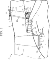
- FIG. 1 illustrates an embodiment of a stator-vane structure according to the present invention. This embodiment will be described with fan exit guide vanes as stator vanes constituting a turbofan engine, by way of example.
- an annular core channel 4 is formed on an axial center side of an engine inner cylinder 3 in an engine body section 2, while a bypass channel 6 (air channel) is formed between an inner peripheral surface of a fan case 5 that is an outside portion of the engine body section 2 and an outer peripheral surface of the engine inner cylinder 3.
- a fan disc 7 is installed rotatably around an engine axial center (not shown) via a bearing 8.
- This fan disc 7 is integrally connected with a turbine rotor in a low-pressure turbine (not shown) placed in a rear section of the engine 1, which is a downstream side (right side in the figure) of the airflow.
- each rotor blade 10 is equally spaced in a circumferential direction via fit grooves 7a, and spacers 11, 11 are placed at front and rear sections between each rotor blade 10 and each fit groove 7a.
- annular retainers 12, 13 that support the rotor blades 10 are installed integrally in the circumferential direction, respectively.
- the retainer 12 at the front section is connected integrally with a nose cone 14, while the retainer 13 at the rear section is connected coaxially and integrally with a rotor 16 in a low-pressure compressor 15 adjacent to the downstream side of the fan disc 7.
- the multiple rotor blades 10 are rotated with the fan disc 7 so as to introduce air into the core channel 4 and the bypass channel 6.
- This engine 1 is provided with multiple fan exit guide vanes 20 within the bypass channel 6.
- the multiple fan exit guide vanes 20 are placed around the engine inner cylinder 3 so as to straighten a swirling airflow flowing in the bypass channel 6.
- a metallic material such as a titanium alloy or an aluminum alloy, or a composite material combining a thermosetting resin or a thermoplastic resin and carbon fibers or glass fibers or the like is employed, the case of employing the composite material for the stator vane is illustrated in this figure.
- a vane base section 21 on the axial center side (inner side) of this fan exit guide vane 20 is connected to mounting flanges 31a, 31a of a fan frame 31 placed to the engine inner cylinder 3, via a coupling support member 30.
- a vane tip section 22 on a side away from the axial center (outer side) of the fan exit guide vane 20 is connected to mounting flanges 5a, 5a placed on the fan case 5, via a coupling support member 32.
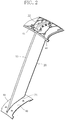
- a sheath 23 which is a metal for erosion prevention, is provided so as to prevent the stator vane from wearing due to collision of objects or the like.
- the sheath 23 is, for example, a titanium alloy plate material, and is adhered so as to cover a leading-edge end of the fan exit guide vane 20.
- FIG. 2 illustrates an overall perspective view of the fan exit guide vane 20
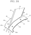
- FIG. 3A illustrates an enlarged perspective view of the vane base section 21 of the fan exit guide vane
- FIG. 3B illustrates an enlarged perspective view of the vane tip section 22 of the fan exit guide vane 20, respectively.
- a liner structure of the fan exit guide vane 20 will be described below in detail based on these figures.
- each of the multiple fan exit guide vanes 20 provided in the engine 1 is provided with inner liners 40 extending in the circumferential direction between the fan exit guide vanes 20, at the vane base section 21, and is provided with outer liners 50 extending in the circumferential direction between the fan exit guide vanes 20 positioned side by side, at the vane tip section 22.
- Each of the inner liners 40 constitutes a part of the engine inner cylinder 3
- each of the outer liners 50 constitutes a part of the fan case 5.
- the inner liners 40 and the outer liners 50 form parts of a channel surface of the bypass channel 6.
- a pair of the inner liners 40, 40 is made to butt against each other so as to clamp therebetween the fan exit guide vane 20 from a vane thickness direction.
- One inner liner 40 has an approximately rectangular shape having four sides: a front side 41 on the airflow upstream side, a rear side 42 on the downstream side, a pressure-side side 43 in contact with a pressure-side of the fan exit guide vane 20, and a suction-side side 44 in contact with a suction-side.
- the pressure-side side 43 and the suction-side side 44 consist of abutting sections 43a, 44a abutting the fan exit guide vane 20, leading-edge sections 43b, 44b positioned closer to a leading-edge side than the fan exit guide vane 20, and trailing-edge sections 43c, 44c positioned closer to a trailing-edge side than the fan exit guide vane 20, respectively.
- the abutting section 44a on the suction-side side 44 has a curved shape along a surface shape of the suction side of the fan exit guide vane 20, in which the leading-edge side surrounds a leading edge of the fan exit guide vane 20 to slightly wrap around the pressure side.
- the other abutting section 43a on the pressure-side side 43 curves along a surface shape of the pressure side of the fan exit guide vane 20, except a portion that the abutting section 44a on the suction-side side 44 partially wraps around.
- the leading-edge division line 45 extends to the front sides 41 from a position offset from the leading edge to the pressure side of the fan exit guide vane 20, in parallel with a line made of a vane chord line of the fan exit guide vane 20 which is extended to the leading-edge side, that is, along a streamline direction.
- a line made of a vane chord line of the fan exit guide vane 20 which is extended to the leading-edge side, that is, along a streamline direction.
- an intersection between the leading-edge division line 45 and a vane surface of the fan exit guide vane 20 is more than or equal to 1.0% and less than or equal to 10.0% of a vane chord length.
- the trailing-edge division line 46 extends to the rear sides 42 from a trailing edge of the fan exit guide vane 20, along a line made of the vane chord line of the fan exit guide vane 20 which is extended to the trailing-edge side, that is, along the streamline direction.
- FIG. 3B the vane tip section 22 of the fan exit guide vane 20 is illustrated in FIG. 3B, and FIG. 3B also illustrates the coupling support member 32 and the like.
- the vane tip section 22 of the fan exit guide vane 20 is held from both sides in the vane thickness direction by a pair of opposed walls 32a, 32b, which are parts of the coupling support member 32.
- Such opposed walls 32a, 32b are connected to the vane tip section 22 at multiple points (four points in FIG. 3B ) by bolts and nuts.
- the coupling support member 32 including these opposed walls 32a, 32b is made of metal such as an aluminum alloy or a titanium alloy, and is connected to the fan case 5 via the mounting flanges 5a, 5a.
- a pair of the outer liners 50, 50 is made to butt against each other so as to clamp therebetween the fan exit guide vane 20 from the vane thickness direction, on a side inner than opposed walls 30a, 30b.
- the outer liner 50 similar to the inner liner 40, has an approximately rectangular shape consisting of a front side 51, a rear side 52, a pressure-side side 53, and a suction-side side 54.
- the pressure-side side 53 and the suction-side side 54 consist of abutting sections 53a, 54a, leading-edge sections 53b, 54b, and trailing-edge sections 53c, 54c, respectively.
- the abutting section 54a on the suction-side side 54 of the outer liner 50 also has the curved shape along the surface shape of the suction side of the fan exit guide vane 20, in which a leading-edge side surrounds the leading edge of the fan exit guide vane 20 to slightly wrap around the pressure side.
- the other abutting section 53a on the pressure-side side 53 curves along the surface shape of the pressure side of the fan exit guide vane 20, except a portion where the abutting section 54a on the suction-side side 54 partially wraps around.
- both the leading-edge sections 53b, 54b on the pressure-side side 53 and the suction-side side 54 are made to butt against each other so as to form a leading-edge division line 55
- both the trailing-edge sections 53c, 54c on the pressure-side side 53 and the suction-side side 54 are made to butt against each other so as to form a trailing-edge division line 56.
- the leading-edge division line 55 extends to the front sides 51 from the position offset from the leading edge to the pressure side of the fan exit guide vane 20, in parallel with the line made of the vane chord line of the fan exit guide vane 20 which is extended to the leading-edge side, that is, along the streamline direction.
- the trailing-edge division line 56 extends to the rear sides 52 from the trailing edge of the fan exit guide vane 20, along the line made of the vane chord line of the fan exit guide vane 20 which is extended to the trailing-edge side, that is, along the streamline direction.
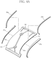
- FIG. 4A illustrates an exploded view of the vane tip section of the fan exit guide vane
- FIG. 4B illustrates a cross-sectional view along an A-A line in FIG. 3B .
- rubber fillets 57a, 57b are mounted on edge portions of the abutting sections 53a, 54a on the pressure-side side 53 and the suction-side side 54 of the outer liner 50, respectively, and tube seals 58a, 58b are mounted on outer edge portions of the abutting sections 53a, 54a on the pressure-side side 53 and the suction-side side 54.
- the rubber fillets 57a, 57b and the tube seals 58a, 58b are made of elastic members, such as rubber, respectively, and are attached to the outer liner 50, for example, by an adhesive or the like. Then, as illustrated in FIG. 4B , the rubber fillets 57a, 57b extend toward the fan exit guide vane 20 so as to fill a gap between them and the fan exit guide vane 20. Moreover, the tube seals 58a, 58b are provided on an outside surface of the outer liner so as to fill a gap between them and the opposed walls 32a, 32b of the coupling support member 32. It should be noted that, although not shown, rubber fillets and tube seals are also provided on the inner liner 40, similar to the outer liner 50.
- leading-edge division lines 45, 55 are offset from the leading edge to the pressure side of the fan exit guide vane 20, and the abutting sections 44a, 54a on the suction-side sides 44, 54 of the inner liner 40 and the outer liner 50 surround the leading edge of the fan exit guide vane 20.
- the division lines do not exist at the leading edge of the fan exit guide vane 20 having significant aerodynamic influence, and influence of the pressure loss or the like may be minimized.
- the inner liner 40 and the outer liner 50 are mounted on the fan exit guide vane 20 via the rubber fillets 57a, 57b, and mounted on the opposed walls 32a, 32b of the coupling support member 30, 32 via the tube seals 58a, 58b, respectively.
- the air does not exit from the gap, and the pressure loss can be more reliably reduced.
- fan exit guide vane 20 of the above described embodiment is provided in the bypass channel of the turbofan engine 1
- the fan exit guide vane 20 can also be applied to stator vanes provided at other positions in the turbofan engine.
- a first aspect of the present invention includes a fan case of a turbofan engine; an engine body section of the turbofan engine; multiple stator vanes that connect the fan case and the engine body section; and multiple liners that form a channel surface between end sections of the stator vanes that are adjacent to each other, wherein the liners that are adjacent to each other are made to butt against each other so as to clamp therebetween the stator vane, and a division line that is formed between the liners on a leading-edge side of the stator vane is along a streamline direction.
- the division line between the liners extends to front sides of the liners from a position offset from a leading edge to a pressure side of the stator vane in the first aspect.
- an amount of offset of the division line between the liners from the leading edge to the pressure side of the stator vane is more than or equal to 1.0% and less than or equal to 10.0% with respect to a vane chord length of the stator vane in the second aspect.
- a stator-vane structure according to any of the first to third aspects is employed as a stator-vane structure constituting the turbofan engine.
Landscapes
- Engineering & Computer Science (AREA)
- Mechanical Engineering (AREA)
- General Engineering & Computer Science (AREA)
- Chemical & Material Sciences (AREA)
- Combustion & Propulsion (AREA)
- Structures Of Non-Positive Displacement Pumps (AREA)
Claims (3)
- Statorschaufelstruktur, umfassend:ein Bläsergehäuse (5) eines Bläsertriebwerks;einen Triebwerkskörperabschnitt (2) des Bläsertriebwerks;mehrere Statorschaufeln (20), die das Bläsergehäuse und den Triebwerkskörperabschnitt verbinden;
undmehrere Auskleidungen (40), die eine Kanalfläche zwischen Endabschnitten der aneinander angrenzenden Statorschaufeln bilden,wobei die aneinander angrenzenden Auskleidungen so ausgeführt sind, dass sie derart gegeneinander stoßen, dass sie die Statorschaufel zwischen sich klemmen, dadurch gekennzeichnet, dasseine Trennlinie (45), die zwischen den Auskleidungen auf einer Vorderkantenseite der Statorschaufel ausgebildet ist, parallel zu einer Linie verläuft, die aus einer Schaufelsehnenlinie der Statorschaufel besteht, die sich bis zur Vorderkantenseite erstreckt;und dasssich die Trennlinie zwischen den Auskleidungen zu Vorderseiten der Auskleidungen von einer Position, die von einer Vorderkante versetzt ist, zu einer Druckseite der Statorschaufel erstreckt. - Statorschaufelstruktur nach Anspruch 1, wobei ein Versatzbetrag der Trennlinie zwischen den Auskleidungen von der Vorderkante zu der Druckseite der Statorschaufel größer oder gleich 1,0 % und kleiner oder gleich 10,0 % in Bezug auf eine Schaufelsehnenlänge der Statorschaufel ist.
- Bläsertriebwerk, umfassend die Statorschaufelstruktur nach Anspruch 1 oder 2.
Applications Claiming Priority (2)
| Application Number | Priority Date | Filing Date | Title |
|---|---|---|---|
| JP2014206430A JP6525130B2 (ja) | 2014-10-07 | 2014-10-07 | 静翼構造及びこれを用いたターボファンエンジン |
| PCT/JP2015/077962 WO2016056463A1 (ja) | 2014-10-07 | 2015-10-01 | 静翼構造及びこれを用いたターボファンエンジン |
Publications (3)
| Publication Number | Publication Date |
|---|---|
| EP3205870A1 EP3205870A1 (de) | 2017-08-16 |
| EP3205870A4 EP3205870A4 (de) | 2018-06-06 |
| EP3205870B1 true EP3205870B1 (de) | 2019-05-29 |
Family
ID=55653078
Family Applications (1)
| Application Number | Title | Priority Date | Filing Date |
|---|---|---|---|
| EP15848210.9A Active EP3205870B1 (de) | 2014-10-07 | 2015-10-01 | Statorschaufelstruktur und bläsertriebwerk damit |
Country Status (7)
| Country | Link |
|---|---|
| US (1) | US10590956B2 (de) |
| EP (1) | EP3205870B1 (de) |
| JP (1) | JP6525130B2 (de) |
| CN (1) | CN107076053B (de) |
| CA (1) | CA2962733C (de) |
| RU (1) | RU2672545C2 (de) |
| WO (1) | WO2016056463A1 (de) |
Families Citing this family (7)
| Publication number | Priority date | Publication date | Assignee | Title |
|---|---|---|---|---|
| JP6525130B2 (ja) * | 2014-10-07 | 2019-06-05 | 株式会社Ihi | 静翼構造及びこれを用いたターボファンエンジン |
| WO2019240754A2 (en) * | 2018-06-11 | 2019-12-19 | Siemens Aktiengesellschaft | Composite ceramic and metallic vane for combustion turbine engine |
| US11047248B2 (en) | 2018-06-19 | 2021-06-29 | General Electric Company | Curved seal for adjacent gas turbine components |
| FR3124214A1 (fr) * | 2021-06-18 | 2022-12-23 | Safran Aircraft Engines | Module de soufflante a joint ameliore |
| US11905965B2 (en) * | 2022-03-07 | 2024-02-20 | Air Distribution Technologies Ip, Llc | Fan wheel systems and methods |
| CN114991877B (zh) * | 2022-08-03 | 2022-11-18 | 成都中科翼能科技有限公司 | 一种涡轮转子的组合式叶片结构 |
| FR3138904B1 (fr) * | 2022-08-22 | 2024-07-12 | Safran Aircraft Engines | Aubage fixe de turbomachine comprenant des aubes à calage variable |
Family Cites Families (17)
| Publication number | Priority date | Publication date | Assignee | Title |
|---|---|---|---|---|
| US3335483A (en) * | 1961-12-19 | 1967-08-15 | Gen Electric | Method of manufacturing a stator assembly for turbomachines |
| GB9602129D0 (en) * | 1996-02-02 | 1996-04-03 | Rolls Royce Plc | Rotors for gas turbine engines |
| GB9915637D0 (en) * | 1999-07-06 | 1999-09-01 | Rolls Royce Plc | A rotor seal |
| US6579065B2 (en) * | 2001-09-13 | 2003-06-17 | General Electric Co. | Methods and apparatus for limiting fluid flow between adjacent rotor blades |
| JP2004092612A (ja) * | 2002-09-04 | 2004-03-25 | Mitsubishi Heavy Ind Ltd | シュラウド及び静翼 |
| FR2858351B1 (fr) | 2003-07-31 | 2006-01-13 | Snecma Moteurs | Plate-forme inter-aubes a flechissement lateral, pour un support d'aubes de turboreacteur |
| AT503840B1 (de) * | 2006-06-30 | 2010-09-15 | Facc Ag | Leitschaufelanordnung für ein triebwerk |
| GB0614640D0 (en) * | 2006-07-22 | 2006-08-30 | Rolls Royce Plc | An annulus filler seal |
| US7581924B2 (en) | 2006-07-27 | 2009-09-01 | Siemens Energy, Inc. | Turbine vanes with airfoil-proximate cooling seam |
| EP2075414A1 (de) * | 2007-12-27 | 2009-07-01 | Techspace aero | Stator-Innenring für die Begrenzung des Primärflusses des Triebwerks eines Luftfahrzeugs |
| US20100080692A1 (en) * | 2008-09-30 | 2010-04-01 | Courtney James Tudor | Fairing seal |
| US20100077612A1 (en) * | 2008-09-30 | 2010-04-01 | Courtney James Tudor | Method of manufacturing a fairing with an integrated seal |
| US20110003233A1 (en) * | 2009-06-19 | 2011-01-06 | Donald Bennet Hilliard | Solid oxide electrolytic device |
| GB0914187D0 (en) * | 2009-08-14 | 2009-09-16 | Rolls Royce Plc | A sealing assembly |
| JP2011085056A (ja) * | 2009-10-15 | 2011-04-28 | General Electric Co <Ge> | 一体形シールを有するフェアリングシールを製作する方法 |
| FR2956876B1 (fr) * | 2010-02-26 | 2012-10-19 | Snecma | Module structural et aerodynamique d'un carter de turbomachine et structure de carter comportant une pluralite d'un tel module |
| JP6525130B2 (ja) * | 2014-10-07 | 2019-06-05 | 株式会社Ihi | 静翼構造及びこれを用いたターボファンエンジン |
-
2014
- 2014-10-07 JP JP2014206430A patent/JP6525130B2/ja active Active
-
2015
- 2015-10-01 CN CN201580053526.9A patent/CN107076053B/zh not_active Expired - Fee Related
- 2015-10-01 EP EP15848210.9A patent/EP3205870B1/de active Active
- 2015-10-01 RU RU2017115848A patent/RU2672545C2/ru active
- 2015-10-01 WO PCT/JP2015/077962 patent/WO2016056463A1/ja active Application Filing
- 2015-10-01 CA CA2962733A patent/CA2962733C/en active Active
-
2017
- 2017-03-24 US US15/468,693 patent/US10590956B2/en active Active
Non-Patent Citations (1)
| Title |
|---|
| None * |
Also Published As
| Publication number | Publication date |
|---|---|
| JP6525130B2 (ja) | 2019-06-05 |
| CN107076053A (zh) | 2017-08-18 |
| US20170198718A1 (en) | 2017-07-13 |
| EP3205870A4 (de) | 2018-06-06 |
| RU2017115848A3 (de) | 2018-11-13 |
| RU2672545C2 (ru) | 2018-11-15 |
| CA2962733A1 (en) | 2016-04-14 |
| CN107076053B (zh) | 2018-12-28 |
| CA2962733C (en) | 2020-01-14 |
| WO2016056463A1 (ja) | 2016-04-14 |
| JP2016075230A (ja) | 2016-05-12 |
| RU2017115848A (ru) | 2018-11-13 |
| EP3205870A1 (de) | 2017-08-16 |
| US10590956B2 (en) | 2020-03-17 |
Similar Documents
| Publication | Publication Date | Title |
|---|---|---|
| EP3205870B1 (de) | Statorschaufelstruktur und bläsertriebwerk damit | |
| EP2935789B2 (de) | Tragflächenanordnung mit gepaarter rückwandkonturierung | |
| EP2256299B1 (de) | Deflektor für eine Gasturbinenstreben- und -schaufelanordnung | |
| US8128354B2 (en) | Gas turbine engine | |
| US8511983B2 (en) | LPC exit guide vane and assembly | |
| US9222363B2 (en) | Angular sector of a stator for a turbine engine compressor, a turbine engine stator, and a turbine engine including such a sector | |
| EP2617961A1 (de) | Turbinenschneckenstruktur | |
| US10815798B2 (en) | Turbine engine blade with leading edge strip | |
| US11236627B2 (en) | Turbomachine stator element | |
| EP3922817A1 (de) | Verfahren zum entwurf einer schaufel für axiallüfter, verdichter und turbine und durch die besagte konstruktion erhaltene schaufel | |
| US20130315745A1 (en) | Airfoil mateface sealing | |
| US20130333350A1 (en) | Airfoil including adhesively bonded shroud | |
| CN109695480B (zh) | 包含矫直组件的涡轮发动机 | |
| US8920117B2 (en) | Fabricated gas turbine duct | |
| US20190330992A1 (en) | Blade or vane, blade or vane segment and assembly for a turbomachine, and turbomachine | |
| CN115176070A (zh) | 涡轮机部件或部件的组合件 | |
| US9068475B2 (en) | Stator vane assembly | |
| JP2007270833A (ja) | 形状を局所的に再加工したステータ翼とこのような翼を備えるステータ部分、圧縮ステージ、圧縮機およびターボ機械 | |
| US11280204B2 (en) | Air flow straightening assembly and turbomachine including such an assembly | |
| JP6189432B2 (ja) | ガスタービンエンジン用支持構造 | |
| US11852018B1 (en) | Turbine nozzle with planar surface adjacent side slash face | |
| US20170159494A1 (en) | Steam turbine nozzle segment with complete sidewall and integrated hook design | |
| JP7260845B2 (ja) | タービン動翼 | |
| CN116601376A (zh) | 用于涡轮发动机的空气流矫直级 |
Legal Events
| Date | Code | Title | Description |
|---|---|---|---|
| STAA | Information on the status of an ep patent application or granted ep patent |
Free format text: STATUS: THE INTERNATIONAL PUBLICATION HAS BEEN MADE |
|
| PUAI | Public reference made under article 153(3) epc to a published international application that has entered the european phase |
Free format text: ORIGINAL CODE: 0009012 |
|
| STAA | Information on the status of an ep patent application or granted ep patent |
Free format text: STATUS: REQUEST FOR EXAMINATION WAS MADE |
|
| 17P | Request for examination filed |
Effective date: 20170508 |
|
| AK | Designated contracting states |
Kind code of ref document: A1 Designated state(s): AL AT BE BG CH CY CZ DE DK EE ES FI FR GB GR HR HU IE IS IT LI LT LU LV MC MK MT NL NO PL PT RO RS SE SI SK SM TR |
|
| AX | Request for extension of the european patent |
Extension state: BA ME |
|
| DAV | Request for validation of the european patent (deleted) | ||
| DAX | Request for extension of the european patent (deleted) | ||
| A4 | Supplementary search report drawn up and despatched |
Effective date: 20180507 |
|
| RIC1 | Information provided on ipc code assigned before grant |
Ipc: F01D 9/04 20060101ALI20180430BHEP Ipc: F02C 7/00 20060101ALI20180430BHEP Ipc: F02K 3/06 20060101AFI20180430BHEP |
|
| GRAP | Despatch of communication of intention to grant a patent |
Free format text: ORIGINAL CODE: EPIDOSNIGR1 |
|
| STAA | Information on the status of an ep patent application or granted ep patent |
Free format text: STATUS: GRANT OF PATENT IS INTENDED |
|
| INTG | Intention to grant announced |
Effective date: 20181219 |
|
| GRAS | Grant fee paid |
Free format text: ORIGINAL CODE: EPIDOSNIGR3 |
|
| GRAA | (expected) grant |
Free format text: ORIGINAL CODE: 0009210 |
|
| STAA | Information on the status of an ep patent application or granted ep patent |
Free format text: STATUS: THE PATENT HAS BEEN GRANTED |
|
| AK | Designated contracting states |
Kind code of ref document: B1 Designated state(s): AL AT BE BG CH CY CZ DE DK EE ES FI FR GB GR HR HU IE IS IT LI LT LU LV MC MK MT NL NO PL PT RO RS SE SI SK SM TR |
|
| REG | Reference to a national code |
Ref country code: GB Ref legal event code: FG4D |
|
| REG | Reference to a national code |
Ref country code: CH Ref legal event code: EP |
|
| REG | Reference to a national code |
Ref country code: AT Ref legal event code: REF Ref document number: 1138413 Country of ref document: AT Kind code of ref document: T Effective date: 20190615 |
|
| REG | Reference to a national code |
Ref country code: DE Ref legal event code: R096 Ref document number: 602015031206 Country of ref document: DE |
|
| REG | Reference to a national code |
Ref country code: IE Ref legal event code: FG4D |
|
| REG | Reference to a national code |
Ref country code: NL Ref legal event code: MP Effective date: 20190529 |
|
| REG | Reference to a national code |
Ref country code: LT Ref legal event code: MG4D |
|
| PG25 | Lapsed in a contracting state [announced via postgrant information from national office to epo] |
Ref country code: FI Free format text: LAPSE BECAUSE OF FAILURE TO SUBMIT A TRANSLATION OF THE DESCRIPTION OR TO PAY THE FEE WITHIN THE PRESCRIBED TIME-LIMIT Effective date: 20190529 Ref country code: NO Free format text: LAPSE BECAUSE OF FAILURE TO SUBMIT A TRANSLATION OF THE DESCRIPTION OR TO PAY THE FEE WITHIN THE PRESCRIBED TIME-LIMIT Effective date: 20190829 Ref country code: SE Free format text: LAPSE BECAUSE OF FAILURE TO SUBMIT A TRANSLATION OF THE DESCRIPTION OR TO PAY THE FEE WITHIN THE PRESCRIBED TIME-LIMIT Effective date: 20190529 Ref country code: PT Free format text: LAPSE BECAUSE OF FAILURE TO SUBMIT A TRANSLATION OF THE DESCRIPTION OR TO PAY THE FEE WITHIN THE PRESCRIBED TIME-LIMIT Effective date: 20190930 Ref country code: ES Free format text: LAPSE BECAUSE OF FAILURE TO SUBMIT A TRANSLATION OF THE DESCRIPTION OR TO PAY THE FEE WITHIN THE PRESCRIBED TIME-LIMIT Effective date: 20190529 Ref country code: AL Free format text: LAPSE BECAUSE OF FAILURE TO SUBMIT A TRANSLATION OF THE DESCRIPTION OR TO PAY THE FEE WITHIN THE PRESCRIBED TIME-LIMIT Effective date: 20190529 Ref country code: LT Free format text: LAPSE BECAUSE OF FAILURE TO SUBMIT A TRANSLATION OF THE DESCRIPTION OR TO PAY THE FEE WITHIN THE PRESCRIBED TIME-LIMIT Effective date: 20190529 Ref country code: HR Free format text: LAPSE BECAUSE OF FAILURE TO SUBMIT A TRANSLATION OF THE DESCRIPTION OR TO PAY THE FEE WITHIN THE PRESCRIBED TIME-LIMIT Effective date: 20190529 |
|
| PG25 | Lapsed in a contracting state [announced via postgrant information from national office to epo] |
Ref country code: GR Free format text: LAPSE BECAUSE OF FAILURE TO SUBMIT A TRANSLATION OF THE DESCRIPTION OR TO PAY THE FEE WITHIN THE PRESCRIBED TIME-LIMIT Effective date: 20190830 Ref country code: BG Free format text: LAPSE BECAUSE OF FAILURE TO SUBMIT A TRANSLATION OF THE DESCRIPTION OR TO PAY THE FEE WITHIN THE PRESCRIBED TIME-LIMIT Effective date: 20190829 Ref country code: LV Free format text: LAPSE BECAUSE OF FAILURE TO SUBMIT A TRANSLATION OF THE DESCRIPTION OR TO PAY THE FEE WITHIN THE PRESCRIBED TIME-LIMIT Effective date: 20190529 Ref country code: RS Free format text: LAPSE BECAUSE OF FAILURE TO SUBMIT A TRANSLATION OF THE DESCRIPTION OR TO PAY THE FEE WITHIN THE PRESCRIBED TIME-LIMIT Effective date: 20190529 |
|
| REG | Reference to a national code |
Ref country code: AT Ref legal event code: MK05 Ref document number: 1138413 Country of ref document: AT Kind code of ref document: T Effective date: 20190529 |
|
| PG25 | Lapsed in a contracting state [announced via postgrant information from national office to epo] |
Ref country code: CZ Free format text: LAPSE BECAUSE OF FAILURE TO SUBMIT A TRANSLATION OF THE DESCRIPTION OR TO PAY THE FEE WITHIN THE PRESCRIBED TIME-LIMIT Effective date: 20190529 Ref country code: EE Free format text: LAPSE BECAUSE OF FAILURE TO SUBMIT A TRANSLATION OF THE DESCRIPTION OR TO PAY THE FEE WITHIN THE PRESCRIBED TIME-LIMIT Effective date: 20190529 Ref country code: RO Free format text: LAPSE BECAUSE OF FAILURE TO SUBMIT A TRANSLATION OF THE DESCRIPTION OR TO PAY THE FEE WITHIN THE PRESCRIBED TIME-LIMIT Effective date: 20190529 Ref country code: DK Free format text: LAPSE BECAUSE OF FAILURE TO SUBMIT A TRANSLATION OF THE DESCRIPTION OR TO PAY THE FEE WITHIN THE PRESCRIBED TIME-LIMIT Effective date: 20190529 Ref country code: NL Free format text: LAPSE BECAUSE OF FAILURE TO SUBMIT A TRANSLATION OF THE DESCRIPTION OR TO PAY THE FEE WITHIN THE PRESCRIBED TIME-LIMIT Effective date: 20190529 Ref country code: AT Free format text: LAPSE BECAUSE OF FAILURE TO SUBMIT A TRANSLATION OF THE DESCRIPTION OR TO PAY THE FEE WITHIN THE PRESCRIBED TIME-LIMIT Effective date: 20190529 Ref country code: SK Free format text: LAPSE BECAUSE OF FAILURE TO SUBMIT A TRANSLATION OF THE DESCRIPTION OR TO PAY THE FEE WITHIN THE PRESCRIBED TIME-LIMIT Effective date: 20190529 |
|
| PG25 | Lapsed in a contracting state [announced via postgrant information from national office to epo] |
Ref country code: SM Free format text: LAPSE BECAUSE OF FAILURE TO SUBMIT A TRANSLATION OF THE DESCRIPTION OR TO PAY THE FEE WITHIN THE PRESCRIBED TIME-LIMIT Effective date: 20190529 |
|
| REG | Reference to a national code |
Ref country code: DE Ref legal event code: R097 Ref document number: 602015031206 Country of ref document: DE |
|
| PG25 | Lapsed in a contracting state [announced via postgrant information from national office to epo] |
Ref country code: TR Free format text: LAPSE BECAUSE OF FAILURE TO SUBMIT A TRANSLATION OF THE DESCRIPTION OR TO PAY THE FEE WITHIN THE PRESCRIBED TIME-LIMIT Effective date: 20190529 |
|
| PLBE | No opposition filed within time limit |
Free format text: ORIGINAL CODE: 0009261 |
|
| STAA | Information on the status of an ep patent application or granted ep patent |
Free format text: STATUS: NO OPPOSITION FILED WITHIN TIME LIMIT |
|
| PG25 | Lapsed in a contracting state [announced via postgrant information from national office to epo] |
Ref country code: PL Free format text: LAPSE BECAUSE OF FAILURE TO SUBMIT A TRANSLATION OF THE DESCRIPTION OR TO PAY THE FEE WITHIN THE PRESCRIBED TIME-LIMIT Effective date: 20190529 |
|
| 26N | No opposition filed |
Effective date: 20200303 |
|
| PG25 | Lapsed in a contracting state [announced via postgrant information from national office to epo] |
Ref country code: SI Free format text: LAPSE BECAUSE OF FAILURE TO SUBMIT A TRANSLATION OF THE DESCRIPTION OR TO PAY THE FEE WITHIN THE PRESCRIBED TIME-LIMIT Effective date: 20190529 Ref country code: MC Free format text: LAPSE BECAUSE OF FAILURE TO SUBMIT A TRANSLATION OF THE DESCRIPTION OR TO PAY THE FEE WITHIN THE PRESCRIBED TIME-LIMIT Effective date: 20190529 |
|
| REG | Reference to a national code |
Ref country code: CH Ref legal event code: PL |
|
| PG25 | Lapsed in a contracting state [announced via postgrant information from national office to epo] |
Ref country code: CH Free format text: LAPSE BECAUSE OF NON-PAYMENT OF DUE FEES Effective date: 20191031 Ref country code: LU Free format text: LAPSE BECAUSE OF NON-PAYMENT OF DUE FEES Effective date: 20191001 Ref country code: LI Free format text: LAPSE BECAUSE OF NON-PAYMENT OF DUE FEES Effective date: 20191031 |
|
| REG | Reference to a national code |
Ref country code: BE Ref legal event code: MM Effective date: 20191031 |
|
| PG25 | Lapsed in a contracting state [announced via postgrant information from national office to epo] |
Ref country code: BE Free format text: LAPSE BECAUSE OF NON-PAYMENT OF DUE FEES Effective date: 20191031 |
|
| PG25 | Lapsed in a contracting state [announced via postgrant information from national office to epo] |
Ref country code: IE Free format text: LAPSE BECAUSE OF NON-PAYMENT OF DUE FEES Effective date: 20191001 |
|
| PG25 | Lapsed in a contracting state [announced via postgrant information from national office to epo] |
Ref country code: CY Free format text: LAPSE BECAUSE OF FAILURE TO SUBMIT A TRANSLATION OF THE DESCRIPTION OR TO PAY THE FEE WITHIN THE PRESCRIBED TIME-LIMIT Effective date: 20190529 |
|
| PG25 | Lapsed in a contracting state [announced via postgrant information from national office to epo] |
Ref country code: IS Free format text: LAPSE BECAUSE OF FAILURE TO SUBMIT A TRANSLATION OF THE DESCRIPTION OR TO PAY THE FEE WITHIN THE PRESCRIBED TIME-LIMIT Effective date: 20190929 |
|
| PG25 | Lapsed in a contracting state [announced via postgrant information from national office to epo] |
Ref country code: MT Free format text: LAPSE BECAUSE OF FAILURE TO SUBMIT A TRANSLATION OF THE DESCRIPTION OR TO PAY THE FEE WITHIN THE PRESCRIBED TIME-LIMIT Effective date: 20190529 Ref country code: HU Free format text: LAPSE BECAUSE OF FAILURE TO SUBMIT A TRANSLATION OF THE DESCRIPTION OR TO PAY THE FEE WITHIN THE PRESCRIBED TIME-LIMIT; INVALID AB INITIO Effective date: 20151001 |
|
| PGFP | Annual fee paid to national office [announced via postgrant information from national office to epo] |
Ref country code: IT Payment date: 20210922 Year of fee payment: 7 |
|
| PGFP | Annual fee paid to national office [announced via postgrant information from national office to epo] |
Ref country code: DE Payment date: 20210921 Year of fee payment: 7 |
|
| PG25 | Lapsed in a contracting state [announced via postgrant information from national office to epo] |
Ref country code: MK Free format text: LAPSE BECAUSE OF FAILURE TO SUBMIT A TRANSLATION OF THE DESCRIPTION OR TO PAY THE FEE WITHIN THE PRESCRIBED TIME-LIMIT Effective date: 20190529 |
|
| REG | Reference to a national code |
Ref country code: DE Ref legal event code: R119 Ref document number: 602015031206 Country of ref document: DE |
|
| PG25 | Lapsed in a contracting state [announced via postgrant information from national office to epo] |
Ref country code: DE Free format text: LAPSE BECAUSE OF NON-PAYMENT OF DUE FEES Effective date: 20230503 |
|
| PG25 | Lapsed in a contracting state [announced via postgrant information from national office to epo] |
Ref country code: IT Free format text: LAPSE BECAUSE OF NON-PAYMENT OF DUE FEES Effective date: 20221001 |
|
| PGFP | Annual fee paid to national office [announced via postgrant information from national office to epo] |
Ref country code: GB Payment date: 20230920 Year of fee payment: 9 |
|
| PGFP | Annual fee paid to national office [announced via postgrant information from national office to epo] |
Ref country code: FR Payment date: 20230920 Year of fee payment: 9 |