EP3205597B1 - Système de remplissage pour dispositifs à fumer électronique - Google Patents
Système de remplissage pour dispositifs à fumer électronique Download PDFInfo
- Publication number
- EP3205597B1 EP3205597B1 EP16155542.0A EP16155542A EP3205597B1 EP 3205597 B1 EP3205597 B1 EP 3205597B1 EP 16155542 A EP16155542 A EP 16155542A EP 3205597 B1 EP3205597 B1 EP 3205597B1
- Authority
- EP
- European Patent Office
- Prior art keywords
- nozzle
- liquid
- plunger
- air tube
- opening
- Prior art date
- Legal status (The legal status is an assumption and is not a legal conclusion. Google has not performed a legal analysis and makes no representation as to the accuracy of the status listed.)
- Active
Links
- 230000000391 smoking effect Effects 0.000 title claims description 44
- 239000007788 liquid Substances 0.000 claims description 316
- 239000003571 electronic cigarette Substances 0.000 claims description 86
- 239000012528 membrane Substances 0.000 claims description 31
- 238000007789 sealing Methods 0.000 claims description 16
- 238000000034 method Methods 0.000 claims description 7
- 230000006835 compression Effects 0.000 claims description 5
- 238000007906 compression Methods 0.000 claims description 5
- 238000007373 indentation Methods 0.000 claims description 3
- 239000012858 resilient material Substances 0.000 claims 4
- 238000003860 storage Methods 0.000 description 47
- 238000010438 heat treatment Methods 0.000 description 12
- 239000000443 aerosol Substances 0.000 description 11
- 239000000463 material Substances 0.000 description 11
- 238000000889 atomisation Methods 0.000 description 6
- 230000037361 pathway Effects 0.000 description 6
- 230000009471 action Effects 0.000 description 4
- 230000004913 activation Effects 0.000 description 4
- 238000013461 design Methods 0.000 description 4
- 239000012530 fluid Substances 0.000 description 4
- 239000003595 mist Substances 0.000 description 4
- SNICXCGAKADSCV-JTQLQIEISA-N (-)-Nicotine Chemical compound CN1CCC[C@H]1C1=CC=CN=C1 SNICXCGAKADSCV-JTQLQIEISA-N 0.000 description 3
- PEDCQBHIVMGVHV-UHFFFAOYSA-N Glycerine Chemical compound OCC(O)CO PEDCQBHIVMGVHV-UHFFFAOYSA-N 0.000 description 3
- DNIAPMSPPWPWGF-UHFFFAOYSA-N Propylene glycol Chemical compound CC(O)CO DNIAPMSPPWPWGF-UHFFFAOYSA-N 0.000 description 3
- 230000008901 benefit Effects 0.000 description 3
- 235000019504 cigarettes Nutrition 0.000 description 3
- 238000005429 filling process Methods 0.000 description 3
- 229960002715 nicotine Drugs 0.000 description 3
- SNICXCGAKADSCV-UHFFFAOYSA-N nicotine Natural products CN1CCCC1C1=CC=CN=C1 SNICXCGAKADSCV-UHFFFAOYSA-N 0.000 description 3
- 239000004033 plastic Substances 0.000 description 3
- 235000019505 tobacco product Nutrition 0.000 description 3
- 238000013022 venting Methods 0.000 description 3
- 230000015572 biosynthetic process Effects 0.000 description 2
- 230000008859 change Effects 0.000 description 2
- 238000004891 communication Methods 0.000 description 2
- 230000000881 depressing effect Effects 0.000 description 2
- 239000000835 fiber Substances 0.000 description 2
- 229910052751 metal Inorganic materials 0.000 description 2
- 239000002184 metal Substances 0.000 description 2
- 238000012986 modification Methods 0.000 description 2
- 230000004048 modification Effects 0.000 description 2
- 235000019645 odor Nutrition 0.000 description 2
- 230000008569 process Effects 0.000 description 2
- 230000001007 puffing effect Effects 0.000 description 2
- 230000004044 response Effects 0.000 description 2
- 230000000717 retained effect Effects 0.000 description 2
- 230000035807 sensation Effects 0.000 description 2
- 235000019615 sensations Nutrition 0.000 description 2
- 239000000779 smoke Substances 0.000 description 2
- 238000012546 transfer Methods 0.000 description 2
- 238000009834 vaporization Methods 0.000 description 2
- 230000008016 vaporization Effects 0.000 description 2
- 238000006424 Flood reaction Methods 0.000 description 1
- 241000208125 Nicotiana Species 0.000 description 1
- 235000002637 Nicotiana tabacum Nutrition 0.000 description 1
- 239000004743 Polypropylene Substances 0.000 description 1
- 229910000831 Steel Inorganic materials 0.000 description 1
- 230000002745 absorbent Effects 0.000 description 1
- 239000002250 absorbent Substances 0.000 description 1
- 229910052782 aluminium Inorganic materials 0.000 description 1
- XAGFODPZIPBFFR-UHFFFAOYSA-N aluminium Chemical compound [Al] XAGFODPZIPBFFR-UHFFFAOYSA-N 0.000 description 1
- 230000004888 barrier function Effects 0.000 description 1
- 230000000903 blocking effect Effects 0.000 description 1
- 239000000919 ceramic Substances 0.000 description 1
- 230000000994 depressogenic effect Effects 0.000 description 1
- 238000001514 detection method Methods 0.000 description 1
- 238000001704 evaporation Methods 0.000 description 1
- 239000003889 eye drop Substances 0.000 description 1
- 229940012356 eye drops Drugs 0.000 description 1
- 239000011152 fibreglass Substances 0.000 description 1
- 239000000796 flavoring agent Substances 0.000 description 1
- 235000019634 flavors Nutrition 0.000 description 1
- 230000006870 function Effects 0.000 description 1
- 230000005484 gravity Effects 0.000 description 1
- 230000036541 health Effects 0.000 description 1
- 239000004615 ingredient Substances 0.000 description 1
- 238000003780 insertion Methods 0.000 description 1
- 230000037431 insertion Effects 0.000 description 1
- 238000005304 joining Methods 0.000 description 1
- 210000004072 lung Anatomy 0.000 description 1
- 230000007246 mechanism Effects 0.000 description 1
- -1 polypropylene Polymers 0.000 description 1
- 229920001155 polypropylene Polymers 0.000 description 1
- 239000011148 porous material Substances 0.000 description 1
- 238000003825 pressing Methods 0.000 description 1
- 239000000243 solution Substances 0.000 description 1
- 239000007921 spray Substances 0.000 description 1
- 239000010959 steel Substances 0.000 description 1
- XLYOFNOQVPJJNP-UHFFFAOYSA-N water Substances O XLYOFNOQVPJJNP-UHFFFAOYSA-N 0.000 description 1
Images


Classifications
-
- B—PERFORMING OPERATIONS; TRANSPORTING
- B65—CONVEYING; PACKING; STORING; HANDLING THIN OR FILAMENTARY MATERIAL
- B65D—CONTAINERS FOR STORAGE OR TRANSPORT OF ARTICLES OR MATERIALS, e.g. BAGS, BARRELS, BOTTLES, BOXES, CANS, CARTONS, CRATES, DRUMS, JARS, TANKS, HOPPERS, FORWARDING CONTAINERS; ACCESSORIES, CLOSURES, OR FITTINGS THEREFOR; PACKAGING ELEMENTS; PACKAGES
- B65D47/00—Closures with filling and discharging, or with discharging, devices
- B65D47/04—Closures with discharging devices other than pumps
- B65D47/32—Closures with discharging devices other than pumps with means for venting
-
- A—HUMAN NECESSITIES
- A24—TOBACCO; CIGARS; CIGARETTES; SIMULATED SMOKING DEVICES; SMOKERS' REQUISITES
- A24F—SMOKERS' REQUISITES; MATCH BOXES; SIMULATED SMOKING DEVICES
- A24F40/00—Electrically operated smoking devices; Component parts thereof; Manufacture thereof; Maintenance or testing thereof; Charging means specially adapted therefor
- A24F40/40—Constructional details, e.g. connection of cartridges and battery parts
- A24F40/48—Fluid transfer means, e.g. pumps
- A24F40/485—Valves; Apertures
-
- B—PERFORMING OPERATIONS; TRANSPORTING
- B65—CONVEYING; PACKING; STORING; HANDLING THIN OR FILAMENTARY MATERIAL
- B65B—MACHINES, APPARATUS OR DEVICES FOR, OR METHODS OF, PACKAGING ARTICLES OR MATERIALS; UNPACKING
- B65B3/00—Packaging plastic material, semiliquids, liquids or mixed solids and liquids, in individual containers or receptacles, e.g. bags, sacks, boxes, cartons, cans, or jars
- B65B3/04—Methods of, or means for, filling the material into the containers or receptacles
- B65B3/06—Methods of, or means for, filling the material into the containers or receptacles by gravity flow
-
- B—PERFORMING OPERATIONS; TRANSPORTING
- B65—CONVEYING; PACKING; STORING; HANDLING THIN OR FILAMENTARY MATERIAL
- B65D—CONTAINERS FOR STORAGE OR TRANSPORT OF ARTICLES OR MATERIALS, e.g. BAGS, BARRELS, BOTTLES, BOXES, CANS, CARTONS, CRATES, DRUMS, JARS, TANKS, HOPPERS, FORWARDING CONTAINERS; ACCESSORIES, CLOSURES, OR FITTINGS THEREFOR; PACKAGING ELEMENTS; PACKAGES
- B65D47/00—Closures with filling and discharging, or with discharging, devices
- B65D47/04—Closures with discharging devices other than pumps
- B65D47/20—Closures with discharging devices other than pumps comprising hand-operated members for controlling discharge
- B65D47/24—Closures with discharging devices other than pumps comprising hand-operated members for controlling discharge with poppet valves or lift valves, i.e. valves opening or closing a passageway by a relative motion substantially perpendicular to the plane of the seat
- B65D47/248—Closures with discharging devices other than pumps comprising hand-operated members for controlling discharge with poppet valves or lift valves, i.e. valves opening or closing a passageway by a relative motion substantially perpendicular to the plane of the seat the valve being opened or closed by imparting a motion to the valve stem
-
- B—PERFORMING OPERATIONS; TRANSPORTING
- B65—CONVEYING; PACKING; STORING; HANDLING THIN OR FILAMENTARY MATERIAL
- B65D—CONTAINERS FOR STORAGE OR TRANSPORT OF ARTICLES OR MATERIALS, e.g. BAGS, BARRELS, BOTTLES, BOXES, CANS, CARTONS, CRATES, DRUMS, JARS, TANKS, HOPPERS, FORWARDING CONTAINERS; ACCESSORIES, CLOSURES, OR FITTINGS THEREFOR; PACKAGING ELEMENTS; PACKAGES
- B65D71/00—Bundles of articles held together by packaging elements for convenience of storage or transport, e.g. portable segregating carrier for plural receptacles such as beer cans or pop bottles; Bales of material
- B65D71/50—Bundles of articles held together by packaging elements for convenience of storage or transport, e.g. portable segregating carrier for plural receptacles such as beer cans or pop bottles; Bales of material comprising a plurality of articles held together only partially by packaging elements formed otherwise than by folding a blank
- B65D71/502—Coaxial connections
-
- A—HUMAN NECESSITIES
- A24—TOBACCO; CIGARS; CIGARETTES; SIMULATED SMOKING DEVICES; SMOKERS' REQUISITES
- A24F—SMOKERS' REQUISITES; MATCH BOXES; SIMULATED SMOKING DEVICES
- A24F15/00—Receptacles or boxes specially adapted for cigars, cigarettes, simulated smoking devices or cigarettes therefor
- A24F15/01—Receptacles or boxes specially adapted for cigars, cigarettes, simulated smoking devices or cigarettes therefor specially adapted for simulated smoking devices or cigarettes therefor
- A24F15/015—Receptacles or boxes specially adapted for cigars, cigarettes, simulated smoking devices or cigarettes therefor specially adapted for simulated smoking devices or cigarettes therefor with means for refilling of liquid inhalable precursors
-
- A—HUMAN NECESSITIES
- A24—TOBACCO; CIGARS; CIGARETTES; SIMULATED SMOKING DEVICES; SMOKERS' REQUISITES
- A24F—SMOKERS' REQUISITES; MATCH BOXES; SIMULATED SMOKING DEVICES
- A24F40/00—Electrically operated smoking devices; Component parts thereof; Manufacture thereof; Maintenance or testing thereof; Charging means specially adapted therefor
- A24F40/10—Devices using liquid inhalable precursors
-
- A—HUMAN NECESSITIES
- A61—MEDICAL OR VETERINARY SCIENCE; HYGIENE
- A61M—DEVICES FOR INTRODUCING MEDIA INTO, OR ONTO, THE BODY; DEVICES FOR TRANSDUCING BODY MEDIA OR FOR TAKING MEDIA FROM THE BODY; DEVICES FOR PRODUCING OR ENDING SLEEP OR STUPOR
- A61M2209/00—Ancillary equipment
- A61M2209/04—Tools for specific apparatus
- A61M2209/045—Tools for specific apparatus for filling, e.g. for filling reservoirs
Definitions
- the present invention relates generally to electronic smoking devices and in particular electronic cigarettes. More specifically the present invention relates to filling systems for refilling the reservoir of an electronic smoking device with liquid for vaporization.
- An electronic smoking device is an electronic device that permits the user to simulate the act of smoking by producing an aerosol mist or vapor that is drawn into the lungs through the mouth and then exhaled.
- the inhaled aerosol mist or vapor typically bears nicotine and/or other flavorings without the odor and health risks associated with traditional smoking and tobacco products.
- a user experiences a similar satisfaction and physical sensation to those experienced from a traditional smoking or tobacco product, and exhales an aerosol mist or vapor of similar appearance to the smoke exhaled when using such traditional smoking or tobacco products.
- An electronic smoking device such as an electronic cigarette, typically has a housing accommodating an electric power source (e.g. a single use or rechargeable battery, electrical plug, or other power source), and an electrically operable atomizer.
- the atomizer vaporizes or atomizes liquid supplied from a reservoir and provides vaporized or atomized liquid as an aerosol which is extracted from the electronic smoking device via an air tube and a mouthpiece by a user sucking on the mouthpiece.
- the reservoir may be either a replaceable or refillable container that is coupled to, or located in, the main body of the electronic smoking device and that is typically made of a resilient plastic material such as high-density polypropylene.
- the reservoir may contain a wicking material in which the liquid is stored or alternatively may just be a storage space without any wicking material.
- Control electronics control the activation of the atomizer.
- an airflow sensor is provided within the electronic smoking device, which detects a user puffing on the device (e.g., by sensing an under-pressure or an air flow pattern through the device). The airflow sensor indicates or signals the puff to the control electronics to power up the device and generate vapor.
- a switch is used to power up the electronic cigarette to generate a puff of vapor.
- ingredients of the liquid for producing the aerosol mist or vapor in smoking-substitute devices vary widely, but typically include water and flavorings in a propylene glycol and/or glycerol base. Nicotine may also be included in solutions intended to fulfil a nicotine replacement role, without the harmful products associated with tobacco smoke.
- electronic cigarettes are refilled by removing a mouthpiece from one end of the electronic cigarette to reveal the open end of the refillable reservoir.
- Liquid for atomization is then dispensed from a dispenser that commonly resembles the small dropper bottles used for dispensing eye drops by dripping liquid from the outlet liquid-dispensing tip of the dispenser into the revealed open end of the reservoir by squeezing the walls of the dispenser.
- the air tube providing a gas passage way between the atomizer and the mouthpiece is located in the center of the reservoir.
- the device is then operated to clear the misplaced liquid, this often results in leakage as the misplaced liquid finds its way out of the atomizer through the air passage. Clearing the air passage is also often accompanied by a "gurgling" sound and sensation which users find unpleasant. Having to avoid dripping liquid down the air tube further reduces the cross-section of the available target for dripping liquid into the reservoir.
- Difficulties in refilling an electronic smoking device may cause users to miss the reservoir causing their fingers holding the electronic smoking device to come into contact with the liquid for atomization. Further liquid may spill from the reservoir prior to the mouthpiece of the device being re-attached closing the open end of the reservoir. Often liquid for atomization is relatively greasy and is impregnated with flavors which makes coming into contact unpleasant and undesirable as the liquid needs to be washed off and odors from the liquid may be retained on the hands. Further there is a risk that users may accidentally ingest the liquid if the liquid is not washed off.
- US 2015/0282530 A1 discloses an apparatus comprising a check valve which may be utilized to transfer E-liquid from a storage container into an electronic vaporization device, such that unintended leakage of the E-liquid may not occur.
- a nozzle for a liquid dispensing system for transferring liquid into a liquid reservoir of an electronic smoking device.
- a plunger is provided within a liquid flow path through the nozzle with the plunger being moveable between an open position in which liquid may flow through the liquid flow path and a closed position in which liquid flow through the liquid flow path is restricted with the plunger being biased towards the closed position.
- the nozzle and plunger are configured so that when the nozzle is inserted into an engagement position within an opening providing access to a liquid reservoir which contains an air tube for extracting vapour from an electronic smoking device, the plunger engages with the air tube and is moved from the closed position to the open position.
- the plunger maybe configured to block the air tube to prevent liquid flowing via the flow path though the nozzle from entering the air tube.
- An indentation operable to receive an air tube when the nozzle is in an engagement position may be provided for this purpose
- a sealing member may be mounted on the plunger, wherein the sealing member seals the liquid flow path through the nozzle when said plunger is in the closed position.
- a screw thread, bayonet, magnetic, friction fit, push fit or other type of fitting may be provided on the nozzle which matches a corresponding screw thread at the opening providing access to a liquid reservoir.
- Such a screw thread, bayonet, magnetic, friction fit, push fit or other type of fitting may be positioned on the nozzle so that if the nozzle is inserted into an opening having a matching screw thread, bayonet, magnetic, friction fit, push fit or other type of fitting, the screw threads, bayonet, magnetic, friction fit, push fit or other type of fitting engage each other before the plunger engages with an air tube within the opening.
- the air vent may form part of the liquid flow path or may be separate from the liquid flow path.
- the air vent may be a vent to atmosphere.
- the air vent may be connected to a low pressure reservoir arranged to extract air from the liquid reservoir when the nozzle is in an engagement position.
- the low pressure reservoir may be activated by movement of the plunger so as to extract air from the liquid reservoir when the plunger moves to the open position and hence actively suck air out of a liquid reservoir as liquid flows into the liquid reservoir via the nozzle.
- the nozzle may be attached to a liquid dispenser and used to refill a liquid reservoir accessible via an opening.
- the opening may be a mouthpiece port operable to receive a mouthpiece configured for extracting vapour via the air tube.
- the liquid reservoir may be part of a combined atomizer and liquid reservoir and may be incorporated in an electronic smoking device.
- a membrane having one or more slit valves may be provided adjacent the end of the air tube. If such a membrane is provided, when the nozzle is in an engagement position, the membrane may be caused to be deformed opening the slit valves and permitting liquid to flow into the liquid reservoir.
- a method of refiling a liquid reservoir of an electronic cigarette comprising : inserting a nozzle into an opening providing access to the liquid reservoir wherein the plunger of the nozzle engages with an air tube accessible via the opening and is moved from a closed position to an open position, the plunger when engaged being such as to divert liquid flowing through the nozzle into the liquid reservoir and away from the air tube.
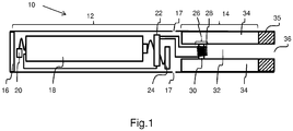
- the power supply portion 12 and atomizer/liquid reservoir portion 14 are typically made of metal, e.g. steel or aluminum, or of hardwearing plastic and act together with the end cap 16 to provide a housing to contain the components of the electronic cigarette 10.
- the power supply portion 12 and an atomizer/liquid reservoir portion 14 may be configured to fit together by a friction push fit, a snap fit, or a bayonet attachment, magnetic fit, or screw threads.
- the atomizer/liquid storage portion 14 of an electronic cigarette may be removable and/or replaceable from a body portion of an electronic cigarette 10, or may be integrally formed with the body portion of the electronic cigarette 10.
- the end cap 16 is provided at the front end of the power supply portion 12.
- the end cap 16 may be made from translucent plastic or other translucent material to allow a light-emitting diode (LED) 20 positioned near the end cap to emit light through the end cap.
- the end cap 16 can be made of metal or other materials that do not allow light to pass.
- An air inlet may be provided in the end cap 16, at the edge of the inlet next to the cylindrical hollow tube, anywhere along the length of the cylindrical hollow tube, or at the connection of the power supply portion 12 and the atomizer/liquid reservoir portion 14.
- Figure 1 shows a pair of air inlets 17 provided at the intersection between the power supply portion 12 and the atomizer/liquid reservoir portion 14.
- the airflow sensor 24 acts as a puff detector, detecting a user puffing or sucking on the atomizer/liquid reservoir portion 14 of the electronic cigarette 10.
- the airflow sensor 24 can be any suitable sensor for detecting changes in airflow or air pressure, such as a microphone switch including a deformable membrane which is caused to move by variations in air pressure.
- the sensor may be a Hall element or an electro-mechanical sensor.
- the air tube 32 is surrounded by a cylindrical liquid reservoir 34 with the ends of the wick 30 abutting or extending into the liquid reservoir 34.
- the wick 30 may be a porous material such as a bundle of fiberglass fibers, with liquid in the liquid reservoir 34 drawn by capillary action from the ends of the wick 30 towards the central portion of the wick 30 encircled by the heating coil 28.
- the liquid reservoir 34 may alternatively include wadding soaked in liquid which encircles the central passage 32 with the ends of the wick 30 abutting the wadding.
- the liquid reservoir 34 may comprise a toroidal cavity arranged to be filled with liquid and with the ends of the wick 30 extending into the toroidal cavity.
- a user sucks on the electronic cigarette 10.
- This causes air to be drawn into the electronic cigarette 10 via one or more air inlets, such as air inlets 17, and to be drawn through the air tube 32 towards the air inhalation port 36.
- the change in air pressure which arises is detected by the airflow sensor 24, which generates an electrical signal that is passed to the control electronics 22.
- the control electronics 22 activate the heating coil 28, which causes liquid present in the wick 30 to be vaporized creating an aerosol (which may comprise gaseous and liquid components) within the air tube 32.
- this aerosol is drawn through the air tube 32 and air inhalation port 36 and inhaled by the user.
- control electronics 22 also activate the LED 20 causing the LED 20 to light up which is visible via the translucent end cap 16 mimicking the appearance of a glowing ember at the end of a conventional cigarette.
- the control electronics 22 also activate the LED 20 causing the LED 20 to light up which is visible via the translucent end cap 16 mimicking the appearance of a glowing ember at the end of a conventional cigarette.
- liquid present in the wick 30 is converted into an aerosol more liquid is drawn into the wick 30 from the liquid reservoir 34 by capillary action and thus is available to be converted into an aerosol through subsequent activation of the heating coil 28.
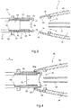
- Figure 2 is a perspective view of a nozzle 38 of a liquid dispenser (with the liquid dispenser omitted) and the atomizer/liquid storage portion 14 of an electronic cigarette
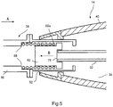
- Figures 3-5 are cross sectional views of the nozzle 38 and an end of the atomizer/liquid storage portion 14 in an uncoupled, an intermediate and coupled configuration.
- the nozzle 38 in this embodiment comprises a first 48 and a second 50 tubular section joined together. Together the first 48 and second tubular sections act to form a housing and define a liquid flow path through the nozzle 38.
- a groove 52 is provided on the exterior wall 54 of the first section 48 of the nozzle 38.
- Flanges 56,58 extend from the ends of the first section 48 and a second section 50 which abut each other which facilitates joining the sections, together allowing the first 48 and second 50 sections to be manufactured as separate units prior to assembly.
- the exterior wall 54 of the first section 48 of the nozzle 38 is slidably engagable within the aperture 42 of the mouthpiece port 39 of the atomizer/liquid storage portion 14 other than the region of the wall 54 comprising the groove 52 which is recessed relative to the size of the aperture 42.
- FIG. 3 shows a cross-sectional view of the nozzle 38
- a helical coil spring 60 is inserted into the cavity of the second section 50 of the nozzle 38 and a plunger 62 extends through the middle of helical coil spring 60 so that shoulder 64 on the plunger 62 may contact an end 60a of the spring 60
- the plunger 62 is inserted into the hollow cylindrical cavity 66 of first section 48 of the nozzle 38.
- the first section 48 and second section 50 are connected together so that the spring 60 is partially compressed such that one end, 60a, abuts the shoulder 64 of the plunger 62 and the other end abuts an interior formation 68 of the nozzle 38 (in the illustrated case a formation on second section 50).
- the compression of the spring 60 causes the plunger 62 to be biased against and abut a partially inwardly extending portion 72 of the first section 48 side wall.
- the exterior wall 54 of the first section 48 of the nozzle 38 is configured to be in slidable engagement with a portion 74 of the inner wall of mouthpiece port 39 of the atomizer/liquid storage portion 14. Also shown is a thinner section 76 of the exterior wall 54 of the first section of the nozzle 38 which forms the bottom of groove 52 illustrated in figure 2 .
- Figure 4 is a schematic illustration of the nozzle 38 partially inserted into the atomizer/liquid storage portion 14 of an electronic cigarette. Not all reference numerals are shown in this figure for clarity purposes.
- the slidable engagement of the outer wall 52 of the first section 48 with the portion 74 of the inner wall of the mouthpiece port 39 of the atomizer/liquid storage portion 14 is clearly illustrated. Additionally, groove 52 can be seen to be in the process of being formed between the thinner portion of the wall 54 and the corresponding portion 74 of the inner wall of mouthpiece port 39 of the atomizer/liquid storage portion 14. Advancing the nozzle 38 toward the atomizer/liquid storage portion 14 in a direction indicated by arrow A will bring the nozzle 38 and the atomizer/liquid storage portion 14 closer to full engagement.
- a re-filling process will be conducted with the nozzle 38 and atomizer/liquid storage portion 14 of an electronic cigarette substantially vertical with the nozzle 38 above the atomizer/liquid storage portion 14 of an electronic cigarette.
- liquid to be dispensed will travel in the direction of arrow A under the influence of gravity down through the nozzle 38 and into the liquid reservoir 34 of the atomizer/liquid storage portion 14 of the electronic cigarette.
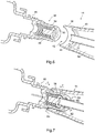
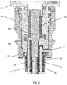
- Figure 6 shows the nozzle 38 and atomizer/liquid storage portion 14 of an electronic cigarette in the uncoupled configuration and figure 7 shows the nozzle 38 and atomizer/liquid storage portion 14 of an electronic cigarette in the coupled configuration.
- the nozzle 38 is disposed in the neck of a liquid dispenser bottle 80.
- the plunger 62 of nozzle 38 is in a closed configuration. With the nozzle 38 inserted in the mouthpiece port 39 of the atomizer/liquid storage portion 14 (i.e.
- the displaced gas may, for example, be vented to atmosphere (as shown in figure 7 ).
- the groove 52 may be configured to form a gas pathway for venting the displaced gas into the dispenser bottle 80.
- FIGS 8 and 9 are cross-sectional views of a nozzle 38 of a liquid dispenser 80 attached to a mouthpiece port 39 at the end of the atomizer/liquid storage portion 14 of an electronic cigarette in a first and a second configuration.
- a plunger 62 is provided within the nozzle 38 with the plunger 62 being biased in the position illustrated in Figure 8 by a coil spring 60.
- portion of the plunger 62 rests against and compresses a seal 86 attached to the plunger 62 which acts to block a liquid flow path and prevent liquid from flowing out of a dispenser bottle 80 to which the nozzle 38 is attached.
- a screw thread 88 is provided on the inside wall of the mouthpiece port 39 at the end of the atomizer/liquid storage portion 14 of an electronic cigarette arranged to match with a corresponding screw thread on a mouthpiece (not shown) when the electronic cigarette is in use.
- a matching screw thread 90 is provided on the exterior wall at the tip of the nozzle 38.
- a further seal 92 is provided on the nozzle 38 adjacent the end of the screw thread 90 remote from the tip of the nozzle 38.
- Figure 9 illustrates the nozzle 38 fully engaged into the mouthpiece port 39 with the plunger 62 in an open configuration.
- the seal 86 provided on the plunger 62 is lifted away from the flow path through the nozzle 38 and therefore ceases to block the flow path and permits liquid to flow from the dispenser 80 into the liquid reservoir as indicted by the arrow on the left hand side of Figure 9 .
- the relative lengths and arrangement of the plunger 62, air tube 32 and screw threads 88,90 are such that when the screw thread 90 of the nozzle 38 initially engages into the screw thread on the mouthpiece port 38, the end surface of the plunger 62 does not rest against the end of the air tube 32. Rather it is only when the screw threads 88, 90 are tightened to the extent which compresses the seal 92 (such as is illustrated in figure 9 ) that the plunger 62 reaches the end of the air tube 32. When this occurs as in the previous embodiment this pushes the plunger 62 against the coil spring 60 and opens a liquid flow path from the liquid dispenser 80 into the liquid reservoir 34 adjacent the air tube 32.
- An air vent 94 separate from the liquid flow path is provided in the nozzle 38 enabling air to vent out of the liquid reservoir 34 as liquid is transferred into the liquid reservoir 34 from the liquid dispenser 80.
- the air flow path via the air vent 94 is indicated by the arrow on the right of the figure.
- the present embodiment has a number of advantages over the first embodiment.
- Refilling an electronic cigarette with liquid for atomization involves a number of distinct stages. First the mouth piece 35 at the end of the electronic cigarette is removed, revealing the end of the liquid reservoir 34. Then a liquid dispenser 80 is utilized to fill the liquid reservoir 34. The liquid dispenser 80 is then removed and then finally the mouthpiece 35 is replaced.
- refillable electronic cigarettes have been described in which a dispenser nozzle 38 is arranged to dispense liquid only when the nozzle 38 is engaged with the liquid reservoir 34 of an electronic cigarette. In the previous embodiments this is achieved by having the operation of the liquid dispenser activated by the engagement of a plunger 62 with the end of an air tube 32 of an electronic cigarette. This addresses the problem of accidental discharge of liquid from the liquid dispenser 80 other than when the liquid dispenser 80 is directed to filling an electronic cigarette.
- liquid dispenser 80 and a liquid reservoir 34 are sealed during a refilling operation it is possible for liquid to leak from the liquid reservoir 34 either prior to attachment of the liquid dispenser 80 (if some residual liquid is present in the liquid reservoir 34 when the electronic cigarette is being refilled) or alternatively immediately after the liquid dispenser 80 has been detached from the electronic cigarette and prior to the reattachment of the mouthpiece 35.
- liquid reservoir 34 In some electronic cigarettes, this problem is avoided by providing wadding, a sponge or other absorbent material within the liquid reservoir 34.
- the liquid reservoir 34 is in the form of an empty cavity or tank.
- a third embodiment of the present invention will now be described in which the leakage of liquid for atomization from an electronic cigarette prior to or immediately after refilling the electronic cigarette and when the mouthpiece port 39 of the electronic cigarette is not enclosed by the presence of a mouthpiece 35 is prevented.
- Figure 10 is a schematic cross-sectional illustration of an atomizer and a liquid reservoir for an electronic cigarette.
- a membrane 96 provided at the end of the liquid reservoir 34 adjacent the end 98 of the air tube 32
- the structure of the atomizer/liquid reservoir is identical to the atomizer/liquid reservoir portion 14 of figure 1 and corresponding features have been identified with the same reference numerals as were used in relation to describing the atomizer/liquid reservoir portion 14 of figure 1 .
- the nozzle 38 contains a plunger 62 which is biased by a spring 60 into a closed configuration in which liquid flow via the nozzle 38 is blocked.
- the plunger 62 engages the end 96 of the air tube 32, this presses the plunger 62 against the spring 60 and opens a liquid flow path through the nozzle 38.
- the plunger 62 caps the end 98 of the air tube 32 and prevents liquid from entering the air tube 32.
- the nozzle 38 presses against the membrane 96 causing the membrane 96 to deform.
- Figure 13 is a plan view of the membrane of figure 11 when the membrane 96 is deformed by the nozzle 38 pressing against the membrane 96.
- the membrane 96 adopts an open configuration in which the slit valves 102 adopt an open configuration as is illustrated in the figure.
- liquid passing via the fluid flow path within the nozzle 38 can enter the liquid reservoir 34 via the open slit valves 102.
- a plunger 62 has been described as capping or blocking the end of an air tube 32 of an electronic cigarette, it will be appreciated that various alternative means for preventing liquid from entering the air tube 32 might be utilised. Thus for example rather than completely covering the end of the air tube, the plunger 62 might be shaped to deflect liquid away from the tube.
- the plunger 62 has been described as having a recess for capping the air tube 32 whereas a plunger 62 with a flat end surface is shown in the second embodiment. It will be appreciated that in other embodiments the end of the plunger might have a protrusion configured to enter into the air tube 32 to block the tube.
- screw threads 88 were provided on the interior of a mouthpiece port 39 and on the exterior of a nozzle 39. It will be appreciated that other configurations of screw thread might be utilised. Thus for example a screw thread might be provided on the exterior or the mouthpiece port and a corresponding screw thread might be provided on an interior wall extending from the end of the nozzle 38.
- a refilling system has been described in which a liquid dispenser 80 is attached to a liquid reservoir 34 of an electronic cigarette via a pair of screw threads 88,90. It will be appreciated that other forms of connection such as magnetic, friction fit or push fit or bayonet fittings could be utilised instead.
- a seal 92 could be provided in the absence of any screw threads with arrangement of the seal 92 and the distances between the plunger 62 and the end of an air tube 32 being such that the seal 92 is caused be compressed prior to the plunger 62 being activated to open a liquid flow path between a liquid dispenser 80 and a liquid reservoir 34.
- a spring 60 to provide the compression force on the plunger 62 to bias it into the closed position
- alternative means of compression could be used.
- One example would be a flexible rubber material which is mildly compressed to bias the plunger 62, but with increased compression of the rubber material, the plunger 62 would move to the open position.
- the rubber material could be assembled to be in tension when it is connected from the plunger 62 to the nozzle 38, and pushing/screwing the nozzle onto the atomiser results in an increase in tension to open the plunger.
- an air vent 94 has been described as enabling air to be vented to atmosphere, in other embodiments the air vent 94 could be connected to a low pressure air reservoir such that air is caused to be sucked out of the liquid reservoir 34. In such embodiments low pressure air reservoir might be activated by the operation of the plunger 62 so that air is sucked from the liquid reservoir 34 as liquid is delivered from the liquid dispenser.
- nozzles 38 containing spring biased plungers 62 have been described as being attached to liquid dispensing bottles, it will be appreciated that such nozzles could be integrally formed with such dispensers or alternative could be attached to such dispensers. It will also be appreciated that other forms of liquid dispenser other than a bottle might be used to store liquid prior to transfer to a liquid reservoir 34 of an electronic cigarette or other electronic smoking device.
- a refilling system in which the flow of liquid is inhibited prior to a nozzle 38 being attached to the mouthpiece port 39 of an electronic cigarette by virtue of the relative arrangement of a plunger 62, an air tube 32 and the screw threads 80,90 provided on a nozzle 38 of a dispensing device and on the mouthpiece port 39 of an electronic cigarette.
- other means could be provided to inhibit fluid flow so as to avoid accidental discharge of liquid.
- a protrusion might be provided on the exterior of the plunger 62 with a corresponding recess being provided within the cavity containing the plunger 62 (or vice versa) where the recess was blocked and user action was required remove the blockage (e.g. by depressing a button or twisting the device).
- a benefit of such a system would be that two actions (e.g. attaching the dispenser to the mouthpiece port 39 and depressing a button etc.) would be required to result in liquid being dispensed.
- a refilling system has been described in which a liquid dispenser 80 is attached to a liquid reservoir 34 of an electronic cigarette via a pair of screw threads 88,90. It will be appreciated that other forms of connection such as magnetic, friction fit or push fit or bayonet fittings could be utilised instead.
- a membrane 96 with four slit valves is illustrated, it will be appreciated that a membrane 96 with more or fewer slit valves 102 might be used. Similarly it will be appreciated that the arrangement of the slit valves 102 may differ from the arrangement illustrated in the figures.
Claims (25)
- Buse (38) pour un système de distribution de liquide pour transférer du liquide dans un réservoir de liquide (34) d'un dispositif à fumer électronique (10), la buse (38) comprenant :- un boîtier définissant un passage d'écoulement de liquide par la buse (38) ; et- un piston (62) fourni dans le passage d'écoulement de liquide, le piston (62) étant déplaçable entre une position ouverte dans laquelle du liquide peut s'écouler à travers le susdit passage d'écoulement de liquide et une position fermée dans laquelle l'écoulement de liquide à travers le susdit passage d'écoulement de liquide est limité lorsque le piston (62) est orienté vers ladite position fermée ;la buse (38) et le piston (62) étant configurés de telle sorte que, lorsque la buse (38) est insérée dans une position d'engagement dans une ouverture permettant l'accès à un réservoir de liquide (34) d'un dispositif à fumer électronique (10) qui contient un tube d'air (32) pour extraire de la vapeur du dispositif à fumer électronique (10), le piston (62) s'engage dans ledit tube d'air (32) et est déplacé de ladite position fermée vers ladite position ouverte, le piston (62) dans ladite position d'engagement étant tel qu'il dévie le liquide s'écoulant via le passage d'écoulement par ladite buse (38) dans le réservoir de liquide (34) et à l'opposé du tube d'air (32),
caractérisée en ce qu'
un évent (94) est fourni permettant à l'air d'être évacué hors d'un réservoir de liquide (34) lorsque la buse (38) est dans une position d'engagement dans une ouverture dans un dispositif à fumer électronique (10). - Buse (38) selon la revendication 1, ledit piston (62) comprenant une surface d'étanchéité (78) conçue pour s'engager dans un tube d'air (32) d'un dispositif à fumer électronique (10) et bloquer ledit tube lorsque la buse (38) est dans une position d'engagement, empêchant du liquide s'écoulant via le passage d'écoulement par la buse (38) de pénétrer dans ledit tube d'air (32).
- Buse (38) selon la revendication 1, un élément d'étanchéité étant monté sur ledit piston (62), ledit élément d'étanchéité fermant hermétiquement ledit passage d'écoulement de liquide lorsque ledit piston (62) est dans ladite position fermée.
- Buse (38) selon la revendication 1, un élément d'étanchéité étant monté sur ladite buse (38), ledit élément d'étanchéité étant configuré pour fermer hermétiquement une ouverture permettant l'accès à un réservoir de liquide (34) qui contient un tube d'air (32) pour extraire de la vapeur du dispositif à fumer électronique (10) lorsque la buse (38) est insérée dans une position d'engagement dans ladite ouverture.
- Buse (38) selon la revendication 4, ladite buse (38) étant configurée de telle sorte que ledit élément d'étanchéité ferme hermétiquement une ouverture permettant l'accès à un réservoir de liquide (34) qui contient un tube d'air (32) pour extraire de la vapeur du dispositif à fumer électronique (10) lorsque la buse (38) est insérée dans une position d'engagement dans ladite ouverture avant que le tube d'air (32) du dispositif à fumer électronique (10) s'engage avec le piston (62) et déplace le piston (62) dans une position ouverte.
- Buse (38) selon la revendication 1, un raccord à filetage, à baïonnette, magnétique, par friction, rapide, ou d'autres types de raccords, est fourni sur ladite buse (38), lequel correspond à un raccord correspondant, à filetage à baïonnette, magnétique, par friction, rapide, ou d'autres types de raccords, sur l'ouverture permettant l'accès à un réservoir de liquide (34).
- Buse (38) selon la revendication 6, le raccord à filetage, à baïonnette, magnétique, par friction, rapide, ou d'autres types de raccords, étant positionné sur ladite buse (38) de telle sorte que la buse (38) est raccordée à un dispositif ayant un raccord correspondant à filetage, à baïonnette, magnétique, par friction, rapide, ou d'autres types de raccords, les raccords à filetage, à filetage, à baïonnette, magnétique, par friction, rapide, ou d'autres types de raccords, s'engageant l'un dans l'autre avant que le piston (62) s'engage dans un tube d'air (32) dans ladite ouverture.
- Buse (38) selon l'une quelconque des revendications précédentes, ledit évent étant raccordé à un réservoir à basse pression conçu pour extraire de l'air du réservoir de liquide (34) lorsque ladite buse (38) est dans une position d'engagement.
- Buse (38) selon la revendication 8, ledit réservoir à basse pression étant activé par le mouvement du susdit piston (62) pour extraire de l'air du réservoir de liquide (34) lorsque ledit piston (62) est dans ladite position ouverte.
- Buse (38) selon la revendication 1, ledit piston (62) ayant une échancrure utilisable pour accueillir le tube d'air (32) d'une cigarette électronique lorsque ladite buse (38) est dans une position d'engagement.
- Buse (38) selon la revendication 1, ledit piston (62) étant orienté vers ladite position fermée par un ressort.
- Buse (38) selon la revendication 1, le mouvement du piston (62) de ladite position fermée vers ladite position ouverte comprimant un matériau élastique, la compression du susdit matériau élastique orientant ledit piston (62) vers ladite position fermée.
- Buse (38) selon la revendication 1, le mouvement du piston (62) de ladite position fermée vers ladite position ouverte étirant un matériau élastique attaché au susdit piston (62), l'étirement du susdit matériau élastique orientant ledit piston (62) vers ladite position fermée.
- Système d'alimentation en liquide pour un dispositif à fumer électronique (10) comprenant :un distributeur de liquide (80) ; etune buse (38) comprenant :un boîtier définissant un passage d'écoulement de liquide par la buse (38) ; et un piston (62) fourni dans le passage d'écoulement de liquide, le piston (62) étant déplaçable entre une position ouverte dans laquelle du liquide peut s'écouler par ledit passage d'écoulement de liquide et une position fermée dans laquelle l'écoulement de liquide par le passage d'écoulement de liquide est limité lorsque le piston (62) est orienté vers ladite position fermée ; la buse (38) et le piston (62) étant configurés de telle sorte que, lorsque la buse (38) est insérée dans une position d'engagement dans une ouverture permettant l'accès à un réservoir de liquide (34) d'un dispositif à fumer électronique (10) qui contient un tube d'air (32) pour extraire de la vapeur du dispositif à fumer électronique (10), le piston (62) s'engage dans ledit tube d'air (32) et est déplacé de ladite position fermée vers ladite position ouverte, le piston (62) dans ladite position d'engagement étant tel qu'il dévie le liquide s'écoulant via le passage d'écoulement par ladite buse (38) dans le réservoir de liquide (34) et à l'opposé du tube d'air (32),caractérisé en ce qu'
un évent (94) est fourni permettant à l'air d'être évacué hors d'un réservoir de liquide (34) lorsque la buse (38) est dans une position d'engagement dans une ouverture dans un dispositif à fumer électronique (10). - Système d'alimentation en liquide pour un dispositif à fumer électronique (10) selon la revendication 14, comprenant en outre : un dispositif à fumer électronique (10), comprenant un réservoir de liquide (34), le réservoir de liquide (34) étant accessible via une ouverture, un tube d'air (32) pour extraire de la vapeur du dispositif à fumer électronique (10) étant accessible via ladite ouverture.
- Système d'alimentation en liquide pour un dispositif à fumer électronique (10) selon la revendication 15, ladite ouverture étant un port à embout (39) utilisable pour accueillir un embout (35) configuré pour extraire de la vapeur via ledit tube d'air (32).
- Système d'alimentation en liquide selon la revendication 15, une membrane (96) ayant une ou plusieurs vannes à fente (102) étant fournie de façon adjacente à l'extrémité du tube d'air (32) accessible via ladite ouverture, ladite buse (38) étant dans la susdite position d'engagement, la déformation de ladite membrane (96) étant provoquée, ouvrant lesdites vannes à fente (102) et permettant à du liquide de s'écouler dans ledit réservoir de liquide (34).
- Réservoir de liquide (34) pour un dispositif à fumer électronique (10), comprenant :une partie de corps ayant une cavité centrale accessible via une ouverture ;un tube d'air (32) pour extraire de la vapeur d'un dispositif à fumer électronique (10) fourni dans ladite cavité centrale, accessible via ladite ouverture ; etune membrane (96) ayant une ou plusieurs vannes à fente (102) fournies de façon adjacente à l'extrémité du tube d'air (32) accessible via ladite ouverture.
- Réservoir de liquide (34) selon la revendication 18, ladite ouverture étant un port à embout (39) utilisable pour accueillir un embout (35) configuré pour extraire de la vapeur via ledit tube d'air (32).
- Réservoir de liquide (34) selon la revendication 19, comprenant en outre un atomiseur (26) utilisable lorsque connecté à une alimentation en énergie (18) pour atomiser du liquide stocké dans le réservoir de liquide (34).
- Dispositif à fumer électronique (10) comprenant :une alimentation en énergie (18) ;un réservoir (34) comprenant :une partie de corps ayant une cavité centrale accessible via une ouverture ; etun tube d'air (32) pour extraire de la vapeur d'un dispositif à fumer électronique (10)fourni dans ladite cavité centrale et accessible via ladite ouverture ;une membrane (96) ayant une ou plusieurs vannes à fente (102) fournies de façon adjacente à l'extrémité du tube d'air (32) accessible via ladite ouverture ;un atomiseur (26) utilisable lorsque connecté à une alimentation en énergie (18) pour atomiser du liquide stocké dans le réservoir de liquide (34).
- Procédé de remplissage d'un réservoir de liquide (34) d'un dispositif à fumer électronique (10) comprenant :alimenter un système d'alimentation en liquide selon la revendication 15 ;insérer la buse (38) dans l'ouverture fournissant un accès au réservoir de liquide (34) de telle sorte que le piston (62) de la buse s'engage dans le tube d'air (32) et est déplacé de ladite position fermée vers ladite position ouverte, le piston (62) dans ladite position d'engagement étant tel qu'il dévie du liquide s'écoulant via le passage d'écoulement par ladite buse (38) dans le réservoir de liquide (34) et à l'opposé du tube d'air (32).
- Procédé selon la revendication 22, un raccord à filetage (88), à baïonnette, magnétique, par friction, rapide, ou d'autres types de raccords, étant fourni sur ladite buse (38), lequel correspond à un raccord correspondant à filetage (88), à baïonnette, magnétique, par friction, rapide, ou d'autres types de raccords, sur l'ouverture permettant l'accès au réservoir de liquide (34), le raccord à filetage (88), à baïonnette, magnétique, par friction, rapide, ou d'autres types de raccords, étant positionné sur ladite buse (38) de telle sorte que, lorsque la buse (38) est insérée dans l'ouverture, lesdits raccords à filetage (88), à baïonnette, magnétique, par friction, rapide, ou d'autres types de raccords, s'engagent l'un dans l'autre avant que le piston (34) s'engage dans un tube d'air (88) dans ladite ouverture.
- Procédé selon la revendication 22, un joint étant fourni sur ladite buse (38), ledit joint fermant hermétiquement ladite ouverture lorsque ladite buse (38) est insérée dans ladite ouverture avant que le piston (62) s'engage dans le tube d'air (32) dans ladite ouverture.
- Procédé selon la revendication 22, une membrane (96) ayant une ou plusieurs vannes à fente (102) étant fournie de façon adjacente à l'extrémité du tube d'air (32) accessible via ladite ouverture, ladite buse (38) étant dans la susdite position d'engagement, la déformation de ladite membrane (96) étant provoquée, ouvrant lesdites vannes à fente (102) et permettant à du liquide de s'écouler dans ledit réservoir de liquide (34).
Priority Applications (6)
| Application Number | Priority Date | Filing Date | Title |
|---|---|---|---|
| EP16155542.0A EP3205597B1 (fr) | 2016-02-12 | 2016-02-12 | Système de remplissage pour dispositifs à fumer électronique |
| PL16155542T PL3205597T3 (pl) | 2016-02-12 | 2016-02-12 | System napełniania do elektronicznych urządzeń do palenia |
| US16/077,026 US20190031407A1 (en) | 2016-02-12 | 2017-02-10 | Filling system for electronic smoking devices |
| PCT/EP2017/052989 WO2017137554A1 (fr) | 2016-02-12 | 2017-02-10 | Système de remplissage pour dispositifs à fumer électroniques |
| CN201780018907.2A CN109415143B (zh) | 2016-02-12 | 2017-02-10 | 电子吸烟装置和用于电子吸烟装置的方法 |
| US17/127,286 US11208240B2 (en) | 2016-02-12 | 2020-12-18 | Filling system for electronic smoking devices |
Applications Claiming Priority (1)
| Application Number | Priority Date | Filing Date | Title |
|---|---|---|---|
| EP16155542.0A EP3205597B1 (fr) | 2016-02-12 | 2016-02-12 | Système de remplissage pour dispositifs à fumer électronique |
Publications (2)
| Publication Number | Publication Date |
|---|---|
| EP3205597A1 EP3205597A1 (fr) | 2017-08-16 |
| EP3205597B1 true EP3205597B1 (fr) | 2019-04-03 |
Family
ID=55353138
Family Applications (1)
| Application Number | Title | Priority Date | Filing Date |
|---|---|---|---|
| EP16155542.0A Active EP3205597B1 (fr) | 2016-02-12 | 2016-02-12 | Système de remplissage pour dispositifs à fumer électronique |
Country Status (5)
| Country | Link |
|---|---|
| US (2) | US20190031407A1 (fr) |
| EP (1) | EP3205597B1 (fr) |
| CN (1) | CN109415143B (fr) |
| PL (1) | PL3205597T3 (fr) |
| WO (1) | WO2017137554A1 (fr) |
Families Citing this family (43)
| Publication number | Priority date | Publication date | Assignee | Title |
|---|---|---|---|---|
| US20160345631A1 (en) | 2005-07-19 | 2016-12-01 | James Monsees | Portable devices for generating an inhalable vapor |
| US10279934B2 (en) | 2013-03-15 | 2019-05-07 | Juul Labs, Inc. | Fillable vaporizer cartridge and method of filling |
| US10076139B2 (en) | 2013-12-23 | 2018-09-18 | Juul Labs, Inc. | Vaporizer apparatus |
| FI3491948T4 (fi) | 2013-12-23 | 2024-05-06 | Juul Labs International Inc | Höyrystyslaitejärjestelmiä |
| USD825102S1 (en) | 2016-07-28 | 2018-08-07 | Juul Labs, Inc. | Vaporizer device with cartridge |
| US20160366947A1 (en) | 2013-12-23 | 2016-12-22 | James Monsees | Vaporizer apparatus |
| US10159282B2 (en) | 2013-12-23 | 2018-12-25 | Juul Labs, Inc. | Cartridge for use with a vaporizer device |
| US10058129B2 (en) | 2013-12-23 | 2018-08-28 | Juul Labs, Inc. | Vaporization device systems and methods |
| USD842536S1 (en) | 2016-07-28 | 2019-03-05 | Juul Labs, Inc. | Vaporizer cartridge |
| EP3821735A1 (fr) | 2014-12-05 | 2021-05-19 | Juul Labs, Inc. | Commande de dose graduée |
| PL3256387T3 (pl) * | 2015-02-13 | 2020-10-19 | Fontem Holdings 1 B.V. | System napełniania elektronicznych urządzeń do palenia |
| EP3081102B1 (fr) * | 2015-04-15 | 2019-06-05 | Fontem Holdings 1 B.V. | Dispositif à fumer électronique |
| WO2017011419A1 (fr) | 2015-07-10 | 2017-01-19 | Pax Labs, Inc. | Dispositifs de vaporisation sans mèche et procédés |
| SG11201806801VA (en) | 2016-02-11 | 2018-09-27 | Juul Labs Inc | Securely attaching cartridges for vaporizer devices |
| EP3413960B1 (fr) | 2016-02-11 | 2021-03-31 | Juul Labs, Inc. | Cartouche de vaporisateur remplissable et procédé de remplissage |
| US10405582B2 (en) | 2016-03-10 | 2019-09-10 | Pax Labs, Inc. | Vaporization device with lip sensing |
| US10244795B2 (en) * | 2016-03-31 | 2019-04-02 | Altria Client Services Llc | Vaporizing assembly comprising sheet heating element and liquid delivery device for an aerosol generating system |
| USD849996S1 (en) | 2016-06-16 | 2019-05-28 | Pax Labs, Inc. | Vaporizer cartridge |
| USD851830S1 (en) | 2016-06-23 | 2019-06-18 | Pax Labs, Inc. | Combined vaporizer tamp and pick tool |
| USD836541S1 (en) | 2016-06-23 | 2018-12-25 | Pax Labs, Inc. | Charging device |
| US11660403B2 (en) | 2016-09-22 | 2023-05-30 | Juul Labs, Inc. | Leak-resistant vaporizer device |
| CA3046954C (fr) | 2016-12-12 | 2024-01-02 | Vmr Products Llc | Cartouche reutilisable pour vaporisateur |
| USD887632S1 (en) | 2017-09-14 | 2020-06-16 | Pax Labs, Inc. | Vaporizer cartridge |
| JP6768772B2 (ja) * | 2018-01-02 | 2020-10-14 | シャンハイ ニュー タバコ プロダクト リサーチ インスティテュート カンパニー,リミティド | エアロゾル発生装置、カートリッジ及び電子タバコ |
| CA3107413A1 (fr) | 2018-07-23 | 2020-01-30 | Juul Labs, Inc. | Gestion de flux d'air pour dispositif vaporisateur |
| KR20210087962A (ko) | 2018-11-05 | 2021-07-13 | 쥴 랩스, 인크. | 기화기 디바이스용 카트리지 |
| EP3890523B1 (fr) * | 2018-12-05 | 2023-02-08 | JT International SA | Mécanisme d'éjection d'atomiseur pour inhalateur d'aérosol |
| DE102019103989A1 (de) * | 2019-02-18 | 2020-08-20 | Hauni Maschinenbau Gmbh | Verbrauchseinheit, Inhalator und Herstellungsverfahren |
| US11606974B2 (en) * | 2019-05-07 | 2023-03-21 | Jupiter Research, Llc | Vape cartridge assembly |
| EP4230066A1 (fr) * | 2019-05-07 | 2023-08-23 | Philip Morris Products S.A. | Leakage prevention structure in a vaporizer device |
| CA3140650A1 (fr) | 2019-05-15 | 2020-11-19 | Christian J. RADO | Vaporisateur personnel et son procede de remplissage |
| US11344066B2 (en) | 2019-05-15 | 2022-05-31 | Vaporous Technologies, Inc. | Personal vaporizer and method for filling same |
| US11839238B2 (en) | 2019-05-15 | 2023-12-12 | Vaporous Technologies, Inc. | Personal vaporizer and method for filling same |
| WO2020239637A1 (fr) * | 2019-05-24 | 2020-12-03 | Nerudia Limited | Dispositif de recharge pour dispositif de distribution d'aérosol |
| EP3741414A1 (fr) * | 2019-05-24 | 2020-11-25 | Nerudia Limited | Dispositif de recharge pour un dispositif d'administration d'aérosol |
| CN211657390U (zh) * | 2020-01-17 | 2020-10-13 | 常州市派腾电子技术服务有限公司 | 注液结构、雾化器及其气溶胶发生装置 |
| KR102360137B1 (ko) * | 2020-03-25 | 2022-02-08 | 주식회사 케이티앤지 | 카트리지 및 이를 포함하는 에어로졸 생성 장치 |
| KR102449809B1 (ko) * | 2020-06-05 | 2022-09-30 | 주식회사 케이티앤지 | 카트리지 및 이를 포함하는 에어로졸 생성 장치 |
| KR102611999B1 (ko) * | 2020-08-06 | 2023-12-08 | 주식회사 케이티앤지 | 카트리지 및 이를 포함하는 에어로졸 생성 장치 |
| US11839239B2 (en) | 2020-08-12 | 2023-12-12 | DES Products Ltd. | Adjustable airflow cartridge for electronic vaporizer |
| EP4216742A1 (fr) * | 2020-09-24 | 2023-08-02 | JT International SA | Cartouche rechargable étanche aux liquides pour un dispositif à fumer électronique |
| CN114673928B (zh) * | 2022-05-25 | 2022-08-23 | 正和集团股份有限公司 | 液态烃装卸系统 |
| US11845104B1 (en) * | 2023-02-04 | 2023-12-19 | Eli Altaras | Liquid solution twist pen method and devices |
Family Cites Families (18)
| Publication number | Priority date | Publication date | Assignee | Title |
|---|---|---|---|---|
| US3115907A (en) * | 1960-04-02 | 1963-12-31 | Francispam | Filling arrangement for a liquefied gas lighter |
| FR2056065A5 (fr) * | 1969-08-27 | 1971-05-14 | Paweck Ag | |
| US4545535A (en) | 1981-03-13 | 1985-10-08 | Knapp Philip B | Liquid metering and dispensing apparatus |
| FR2657846B1 (fr) * | 1990-02-02 | 1992-07-10 | Charlelet Michel | Dispositif pour la consommation de boissons. |
| US6234169B1 (en) * | 1998-08-14 | 2001-05-22 | Arthur Slutsky | Inhaler |
| EP2300329A4 (fr) * | 2008-06-10 | 2011-07-27 | Gen Mills Inc | Conditionnements pour la distribution d aliments liquides et secs |
| US10279934B2 (en) | 2013-03-15 | 2019-05-07 | Juul Labs, Inc. | Fillable vaporizer cartridge and method of filling |
| US20140355969A1 (en) | 2013-05-28 | 2014-12-04 | Sis Resources, Ltd. | One-way valve for atomizer section in electronic cigarettes |
| WO2014194524A1 (fr) * | 2013-06-08 | 2014-12-11 | 吉瑞高新科技股份有限公司 | Cigarette électronique |
| ITBO20130504A1 (it) * | 2013-09-18 | 2015-03-19 | Gd Spa | Metodo ed unita' di riempimento di una cartuccia monouso per sigarette elettroniche con una sostanza liquida. |
| CN103750570B (zh) * | 2014-01-15 | 2016-02-24 | 林光榕 | 方便注液的电子烟及制造方法和注液方法 |
| CN203692552U (zh) * | 2014-02-12 | 2014-07-09 | 刘秋明 | 电子烟 |
| WO2015157224A1 (fr) * | 2014-04-07 | 2015-10-15 | Intrepid Brands, LLC | Appareil et procédés de distribution d'e-liquide |
| CN204157649U (zh) * | 2014-08-27 | 2015-02-18 | 董申恩 | 电子烟雾化嘴以及电子烟 |
| CN204232297U (zh) * | 2014-10-28 | 2015-04-01 | 惠州市吉瑞科技有限公司 | 电子烟 |
| MX368715B (es) | 2014-12-23 | 2019-09-19 | As America Inc | Grifo de extracción operado por sensor. |
| PL3256387T3 (pl) * | 2015-02-13 | 2020-10-19 | Fontem Holdings 1 B.V. | System napełniania elektronicznych urządzeń do palenia |
| US11504489B2 (en) | 2015-07-17 | 2022-11-22 | Rai Strategic Holdings, Inc. | Contained liquid system for refilling aerosol delivery devices |
-
2016
- 2016-02-12 EP EP16155542.0A patent/EP3205597B1/fr active Active
- 2016-02-12 PL PL16155542T patent/PL3205597T3/pl unknown
-
2017
- 2017-02-10 US US16/077,026 patent/US20190031407A1/en not_active Abandoned
- 2017-02-10 WO PCT/EP2017/052989 patent/WO2017137554A1/fr active Application Filing
- 2017-02-10 CN CN201780018907.2A patent/CN109415143B/zh active Active
-
2020
- 2020-12-18 US US17/127,286 patent/US11208240B2/en active Active
Non-Patent Citations (1)
| Title |
|---|
| None * |
Also Published As
| Publication number | Publication date |
|---|---|
| US20210107710A1 (en) | 2021-04-15 |
| CN109415143A (zh) | 2019-03-01 |
| WO2017137554A1 (fr) | 2017-08-17 |
| EP3205597A1 (fr) | 2017-08-16 |
| US20190031407A1 (en) | 2019-01-31 |
| US11208240B2 (en) | 2021-12-28 |
| PL3205597T3 (pl) | 2019-10-31 |
| CN109415143B (zh) | 2021-08-10 |
Similar Documents
| Publication | Publication Date | Title |
|---|---|---|
| US11208240B2 (en) | Filling system for electronic smoking devices | |
| US10988368B2 (en) | Filling system for electronic smoking devices | |
| CN108348007B (zh) | 具有可变容积的液体储存器的电子吸烟装置 | |
| US11224706B2 (en) | Dispenser | |
| EP3165102B1 (fr) | Élément connecteur pour un récipient de recharge déstiné à la recharge de liquide dans un dispositif électronique à fumer | |
| US20230354907A1 (en) | Electronic smoking device with refillable liquid reservoir | |
| EP3143884B1 (fr) | Dispositif à fumer électronique pourvu d'un réservoir de liquide rechargeable | |
| US11111127B2 (en) | System and apparatus | |
| US11197502B2 (en) | System and assembly for refilling a liquid reservoir | |
| US11571024B2 (en) | Electronic smoking device with refillable liquid reservoir | |
| EP3146856B1 (fr) | Seringue de remplissage pour un dispositif de cigarette électronique |
Legal Events
| Date | Code | Title | Description |
|---|---|---|---|
| PUAI | Public reference made under article 153(3) epc to a published international application that has entered the european phase |
Free format text: ORIGINAL CODE: 0009012 |
|
| STAA | Information on the status of an ep patent application or granted ep patent |
Free format text: STATUS: THE APPLICATION HAS BEEN PUBLISHED |
|
| AK | Designated contracting states |
Kind code of ref document: A1 Designated state(s): AL AT BE BG CH CY CZ DE DK EE ES FI FR GB GR HR HU IE IS IT LI LT LU LV MC MK MT NL NO PL PT RO RS SE SI SK SM TR |
|
| AX | Request for extension of the european patent |
Extension state: BA ME |
|
| STAA | Information on the status of an ep patent application or granted ep patent |
Free format text: STATUS: REQUEST FOR EXAMINATION WAS MADE |
|
| 17P | Request for examination filed |
Effective date: 20180130 |
|
| RBV | Designated contracting states (corrected) |
Designated state(s): AL AT BE BG CH CY CZ DE DK EE ES FI FR GB GR HR HU IE IS IT LI LT LU LV MC MK MT NL NO PL PT RO RS SE SI SK SM TR |
|
| GRAP | Despatch of communication of intention to grant a patent |
Free format text: ORIGINAL CODE: EPIDOSNIGR1 |
|
| STAA | Information on the status of an ep patent application or granted ep patent |
Free format text: STATUS: GRANT OF PATENT IS INTENDED |
|
| INTG | Intention to grant announced |
Effective date: 20180822 |
|
| GRAJ | Information related to disapproval of communication of intention to grant by the applicant or resumption of examination proceedings by the epo deleted |
Free format text: ORIGINAL CODE: EPIDOSDIGR1 |
|
| GRAL | Information related to payment of fee for publishing/printing deleted |
Free format text: ORIGINAL CODE: EPIDOSDIGR3 |
|
| GRAS | Grant fee paid |
Free format text: ORIGINAL CODE: EPIDOSNIGR3 |
|
| STAA | Information on the status of an ep patent application or granted ep patent |
Free format text: STATUS: REQUEST FOR EXAMINATION WAS MADE |
|
| GRAR | Information related to intention to grant a patent recorded |
Free format text: ORIGINAL CODE: EPIDOSNIGR71 |
|
| STAA | Information on the status of an ep patent application or granted ep patent |
Free format text: STATUS: GRANT OF PATENT IS INTENDED |
|
| INTC | Intention to grant announced (deleted) | ||
| GRAA | (expected) grant |
Free format text: ORIGINAL CODE: 0009210 |
|
| STAA | Information on the status of an ep patent application or granted ep patent |
Free format text: STATUS: THE PATENT HAS BEEN GRANTED |
|
| INTG | Intention to grant announced |
Effective date: 20190205 |
|
| AK | Designated contracting states |
Kind code of ref document: B1 Designated state(s): AL AT BE BG CH CY CZ DE DK EE ES FI FR GB GR HR HU IE IS IT LI LT LU LV MC MK MT NL NO PL PT RO RS SE SI SK SM TR |
|
| REG | Reference to a national code |
Ref country code: GB Ref legal event code: FG4D |
|
| REG | Reference to a national code |
Ref country code: CH Ref legal event code: EP Ref country code: AT Ref legal event code: REF Ref document number: 1115449 Country of ref document: AT Kind code of ref document: T Effective date: 20190415 |
|
| REG | Reference to a national code |
Ref country code: IE Ref legal event code: FG4D |
|
| REG | Reference to a national code |
Ref country code: DE Ref legal event code: R096 Ref document number: 602016011740 Country of ref document: DE |
|
| REG | Reference to a national code |
Ref country code: NL Ref legal event code: FP |
|
| REG | Reference to a national code |
Ref country code: LT Ref legal event code: MG4D |
|
| REG | Reference to a national code |
Ref country code: AT Ref legal event code: MK05 Ref document number: 1115449 Country of ref document: AT Kind code of ref document: T Effective date: 20190403 |
|
| PG25 | Lapsed in a contracting state [announced via postgrant information from national office to epo] |
Ref country code: LT Free format text: LAPSE BECAUSE OF FAILURE TO SUBMIT A TRANSLATION OF THE DESCRIPTION OR TO PAY THE FEE WITHIN THE PRESCRIBED TIME-LIMIT Effective date: 20190403 Ref country code: HR Free format text: LAPSE BECAUSE OF FAILURE TO SUBMIT A TRANSLATION OF THE DESCRIPTION OR TO PAY THE FEE WITHIN THE PRESCRIBED TIME-LIMIT Effective date: 20190403 Ref country code: SE Free format text: LAPSE BECAUSE OF FAILURE TO SUBMIT A TRANSLATION OF THE DESCRIPTION OR TO PAY THE FEE WITHIN THE PRESCRIBED TIME-LIMIT Effective date: 20190403 Ref country code: NO Free format text: LAPSE BECAUSE OF FAILURE TO SUBMIT A TRANSLATION OF THE DESCRIPTION OR TO PAY THE FEE WITHIN THE PRESCRIBED TIME-LIMIT Effective date: 20190703 Ref country code: PT Free format text: LAPSE BECAUSE OF FAILURE TO SUBMIT A TRANSLATION OF THE DESCRIPTION OR TO PAY THE FEE WITHIN THE PRESCRIBED TIME-LIMIT Effective date: 20190803 Ref country code: AL Free format text: LAPSE BECAUSE OF FAILURE TO SUBMIT A TRANSLATION OF THE DESCRIPTION OR TO PAY THE FEE WITHIN THE PRESCRIBED TIME-LIMIT Effective date: 20190403 Ref country code: FI Free format text: LAPSE BECAUSE OF FAILURE TO SUBMIT A TRANSLATION OF THE DESCRIPTION OR TO PAY THE FEE WITHIN THE PRESCRIBED TIME-LIMIT Effective date: 20190403 Ref country code: CZ Free format text: LAPSE BECAUSE OF FAILURE TO SUBMIT A TRANSLATION OF THE DESCRIPTION OR TO PAY THE FEE WITHIN THE PRESCRIBED TIME-LIMIT Effective date: 20190403 Ref country code: ES Free format text: LAPSE BECAUSE OF FAILURE TO SUBMIT A TRANSLATION OF THE DESCRIPTION OR TO PAY THE FEE WITHIN THE PRESCRIBED TIME-LIMIT Effective date: 20190403 |
|
| PG25 | Lapsed in a contracting state [announced via postgrant information from national office to epo] |
Ref country code: BG Free format text: LAPSE BECAUSE OF FAILURE TO SUBMIT A TRANSLATION OF THE DESCRIPTION OR TO PAY THE FEE WITHIN THE PRESCRIBED TIME-LIMIT Effective date: 20190703 Ref country code: LV Free format text: LAPSE BECAUSE OF FAILURE TO SUBMIT A TRANSLATION OF THE DESCRIPTION OR TO PAY THE FEE WITHIN THE PRESCRIBED TIME-LIMIT Effective date: 20190403 Ref country code: RS Free format text: LAPSE BECAUSE OF FAILURE TO SUBMIT A TRANSLATION OF THE DESCRIPTION OR TO PAY THE FEE WITHIN THE PRESCRIBED TIME-LIMIT Effective date: 20190403 Ref country code: GR Free format text: LAPSE BECAUSE OF FAILURE TO SUBMIT A TRANSLATION OF THE DESCRIPTION OR TO PAY THE FEE WITHIN THE PRESCRIBED TIME-LIMIT Effective date: 20190704 |
|
| PG25 | Lapsed in a contracting state [announced via postgrant information from national office to epo] |
Ref country code: AT Free format text: LAPSE BECAUSE OF FAILURE TO SUBMIT A TRANSLATION OF THE DESCRIPTION OR TO PAY THE FEE WITHIN THE PRESCRIBED TIME-LIMIT Effective date: 20190403 Ref country code: IS Free format text: LAPSE BECAUSE OF FAILURE TO SUBMIT A TRANSLATION OF THE DESCRIPTION OR TO PAY THE FEE WITHIN THE PRESCRIBED TIME-LIMIT Effective date: 20190803 |
|
| REG | Reference to a national code |
Ref country code: DE Ref legal event code: R097 Ref document number: 602016011740 Country of ref document: DE |
|
| PG25 | Lapsed in a contracting state [announced via postgrant information from national office to epo] |
Ref country code: RO Free format text: LAPSE BECAUSE OF FAILURE TO SUBMIT A TRANSLATION OF THE DESCRIPTION OR TO PAY THE FEE WITHIN THE PRESCRIBED TIME-LIMIT Effective date: 20190403 Ref country code: SK Free format text: LAPSE BECAUSE OF FAILURE TO SUBMIT A TRANSLATION OF THE DESCRIPTION OR TO PAY THE FEE WITHIN THE PRESCRIBED TIME-LIMIT Effective date: 20190403 Ref country code: DK Free format text: LAPSE BECAUSE OF FAILURE TO SUBMIT A TRANSLATION OF THE DESCRIPTION OR TO PAY THE FEE WITHIN THE PRESCRIBED TIME-LIMIT Effective date: 20190403 Ref country code: EE Free format text: LAPSE BECAUSE OF FAILURE TO SUBMIT A TRANSLATION OF THE DESCRIPTION OR TO PAY THE FEE WITHIN THE PRESCRIBED TIME-LIMIT Effective date: 20190403 |
|
| PLBE | No opposition filed within time limit |
Free format text: ORIGINAL CODE: 0009261 |
|
| STAA | Information on the status of an ep patent application or granted ep patent |
Free format text: STATUS: NO OPPOSITION FILED WITHIN TIME LIMIT |
|
| PG25 | Lapsed in a contracting state [announced via postgrant information from national office to epo] |
Ref country code: SM Free format text: LAPSE BECAUSE OF FAILURE TO SUBMIT A TRANSLATION OF THE DESCRIPTION OR TO PAY THE FEE WITHIN THE PRESCRIBED TIME-LIMIT Effective date: 20190403 |
|
| 26N | No opposition filed |
Effective date: 20200106 |
|
| PG25 | Lapsed in a contracting state [announced via postgrant information from national office to epo] |
Ref country code: TR Free format text: LAPSE BECAUSE OF FAILURE TO SUBMIT A TRANSLATION OF THE DESCRIPTION OR TO PAY THE FEE WITHIN THE PRESCRIBED TIME-LIMIT Effective date: 20190403 |
|
| PG25 | Lapsed in a contracting state [announced via postgrant information from national office to epo] |
Ref country code: SI Free format text: LAPSE BECAUSE OF FAILURE TO SUBMIT A TRANSLATION OF THE DESCRIPTION OR TO PAY THE FEE WITHIN THE PRESCRIBED TIME-LIMIT Effective date: 20190403 |
|
| REG | Reference to a national code |
Ref country code: CH Ref legal event code: PL |
|
| REG | Reference to a national code |
Ref country code: BE Ref legal event code: MM Effective date: 20200229 |
|
| PG25 | Lapsed in a contracting state [announced via postgrant information from national office to epo] |
Ref country code: MC Free format text: LAPSE BECAUSE OF FAILURE TO SUBMIT A TRANSLATION OF THE DESCRIPTION OR TO PAY THE FEE WITHIN THE PRESCRIBED TIME-LIMIT Effective date: 20190403 Ref country code: LU Free format text: LAPSE BECAUSE OF NON-PAYMENT OF DUE FEES Effective date: 20200212 |
|
| PG25 | Lapsed in a contracting state [announced via postgrant information from national office to epo] |
Ref country code: LI Free format text: LAPSE BECAUSE OF NON-PAYMENT OF DUE FEES Effective date: 20200229 Ref country code: CH Free format text: LAPSE BECAUSE OF NON-PAYMENT OF DUE FEES Effective date: 20200229 |
|
| PG25 | Lapsed in a contracting state [announced via postgrant information from national office to epo] |
Ref country code: IE Free format text: LAPSE BECAUSE OF NON-PAYMENT OF DUE FEES Effective date: 20200212 |
|
| PG25 | Lapsed in a contracting state [announced via postgrant information from national office to epo] |
Ref country code: BE Free format text: LAPSE BECAUSE OF NON-PAYMENT OF DUE FEES Effective date: 20200229 |
|
| PG25 | Lapsed in a contracting state [announced via postgrant information from national office to epo] |
Ref country code: MT Free format text: LAPSE BECAUSE OF FAILURE TO SUBMIT A TRANSLATION OF THE DESCRIPTION OR TO PAY THE FEE WITHIN THE PRESCRIBED TIME-LIMIT Effective date: 20190403 Ref country code: CY Free format text: LAPSE BECAUSE OF FAILURE TO SUBMIT A TRANSLATION OF THE DESCRIPTION OR TO PAY THE FEE WITHIN THE PRESCRIBED TIME-LIMIT Effective date: 20190403 |
|
| PG25 | Lapsed in a contracting state [announced via postgrant information from national office to epo] |
Ref country code: MK Free format text: LAPSE BECAUSE OF FAILURE TO SUBMIT A TRANSLATION OF THE DESCRIPTION OR TO PAY THE FEE WITHIN THE PRESCRIBED TIME-LIMIT Effective date: 20190403 |
|
| PGFP | Annual fee paid to national office [announced via postgrant information from national office to epo] |
Ref country code: FR Payment date: 20230119 Year of fee payment: 8 |
|
| PGFP | Annual fee paid to national office [announced via postgrant information from national office to epo] |
Ref country code: PL Payment date: 20230120 Year of fee payment: 8 Ref country code: IT Payment date: 20230120 Year of fee payment: 8 |
|
| P01 | Opt-out of the competence of the unified patent court (upc) registered |
Effective date: 20230517 |
|
| PGFP | Annual fee paid to national office [announced via postgrant information from national office to epo] |
Ref country code: NL Payment date: 20230119 Year of fee payment: 8 |
|
| REG | Reference to a national code |
Ref country code: DE Ref legal event code: R081 Ref document number: 602016011740 Country of ref document: DE Owner name: FONTEM VENTURES B.V., NL Free format text: FORMER OWNER: FONTEM HOLDINGS 1 B.V., AMSTERDAM, NL |
|
| REG | Reference to a national code |
Ref country code: GB Ref legal event code: 732E Free format text: REGISTERED BETWEEN 20231214 AND 20231220 |
|
| PGFP | Annual fee paid to national office [announced via postgrant information from national office to epo] |
Ref country code: DE Payment date: 20240123 Year of fee payment: 9 Ref country code: GB Payment date: 20240123 Year of fee payment: 9 |