EP3205519A1 - Coupleur - Google Patents
Coupleur Download PDFInfo
- Publication number
- EP3205519A1 EP3205519A1 EP15849245.4A EP15849245A EP3205519A1 EP 3205519 A1 EP3205519 A1 EP 3205519A1 EP 15849245 A EP15849245 A EP 15849245A EP 3205519 A1 EP3205519 A1 EP 3205519A1
- Authority
- EP
- European Patent Office
- Prior art keywords
- parts
- bracket
- joint
- base part
- pair
- Prior art date
- Legal status (The legal status is an assumption and is not a legal conclusion. Google has not performed a legal analysis and makes no representation as to the accuracy of the status listed.)
- Granted
Links
- 238000005452 bending Methods 0.000 claims description 23
- 238000000034 method Methods 0.000 claims description 20
- 238000004519 manufacturing process Methods 0.000 claims description 15
- 229910052751 metal Inorganic materials 0.000 claims description 9
- 239000002184 metal Substances 0.000 claims description 9
- 238000003825 pressing Methods 0.000 claims description 2
- 239000000725 suspension Substances 0.000 description 29
- 230000000694 effects Effects 0.000 description 11
- 229910000831 Steel Inorganic materials 0.000 description 8
- 238000000465 moulding Methods 0.000 description 8
- 239000010959 steel Substances 0.000 description 8
- 238000003466 welding Methods 0.000 description 7
- 238000006073 displacement reaction Methods 0.000 description 5
- 239000000463 material Substances 0.000 description 4
- 238000013461 design Methods 0.000 description 3
- 230000007246 mechanism Effects 0.000 description 3
- 238000012360 testing method Methods 0.000 description 3
- 238000012986 modification Methods 0.000 description 2
- 230000004048 modification Effects 0.000 description 2
- 230000008719 thickening Effects 0.000 description 2
- 229910000838 Al alloy Inorganic materials 0.000 description 1
- 229910001335 Galvanized steel Inorganic materials 0.000 description 1
- RTAQQCXQSZGOHL-UHFFFAOYSA-N Titanium Chemical compound [Ti] RTAQQCXQSZGOHL-UHFFFAOYSA-N 0.000 description 1
- 229910000611 Zinc aluminium Inorganic materials 0.000 description 1
- HXFVOUUOTHJFPX-UHFFFAOYSA-N alumane;zinc Chemical compound [AlH3].[Zn] HXFVOUUOTHJFPX-UHFFFAOYSA-N 0.000 description 1
- 238000005266 casting Methods 0.000 description 1
- 238000007796 conventional method Methods 0.000 description 1
- 230000007423 decrease Effects 0.000 description 1
- 239000008397 galvanized steel Substances 0.000 description 1
- 238000009740 moulding (composite fabrication) Methods 0.000 description 1
- 239000000843 powder Substances 0.000 description 1
- 239000010935 stainless steel Substances 0.000 description 1
- 229910001220 stainless steel Inorganic materials 0.000 description 1
- 230000001629 suppression Effects 0.000 description 1
- 239000010936 titanium Substances 0.000 description 1
- 229910052719 titanium Inorganic materials 0.000 description 1
- 230000037303 wrinkles Effects 0.000 description 1
Images

Classifications
-
- B—PERFORMING OPERATIONS; TRANSPORTING
- B60—VEHICLES IN GENERAL
- B60G—VEHICLE SUSPENSION ARRANGEMENTS
- B60G7/00—Pivoted suspension arms; Accessories thereof
-
- B—PERFORMING OPERATIONS; TRANSPORTING
- B60—VEHICLES IN GENERAL
- B60G—VEHICLE SUSPENSION ARRANGEMENTS
- B60G7/00—Pivoted suspension arms; Accessories thereof
- B60G7/001—Suspension arms, e.g. constructional features
-
- B—PERFORMING OPERATIONS; TRANSPORTING
- B21—MECHANICAL METAL-WORKING WITHOUT ESSENTIALLY REMOVING MATERIAL; PUNCHING METAL
- B21D—WORKING OR PROCESSING OF SHEET METAL OR METAL TUBES, RODS OR PROFILES WITHOUT ESSENTIALLY REMOVING MATERIAL; PUNCHING METAL
- B21D5/00—Bending sheet metal along straight lines, e.g. to form simple curves
- B21D5/16—Folding; Pleating
-
- B—PERFORMING OPERATIONS; TRANSPORTING
- B21—MECHANICAL METAL-WORKING WITHOUT ESSENTIALLY REMOVING MATERIAL; PUNCHING METAL
- B21D—WORKING OR PROCESSING OF SHEET METAL OR METAL TUBES, RODS OR PROFILES WITHOUT ESSENTIALLY REMOVING MATERIAL; PUNCHING METAL
- B21D53/00—Making other particular articles
- B21D53/88—Making other particular articles other parts for vehicles, e.g. cowlings, mudguards
-
- B—PERFORMING OPERATIONS; TRANSPORTING
- B60—VEHICLES IN GENERAL
- B60G—VEHICLE SUSPENSION ARRANGEMENTS
- B60G21/00—Interconnection systems for two or more resiliently-suspended wheels, e.g. for stabilising a vehicle body with respect to acceleration, deceleration or centrifugal forces
- B60G21/02—Interconnection systems for two or more resiliently-suspended wheels, e.g. for stabilising a vehicle body with respect to acceleration, deceleration or centrifugal forces permanently interconnected
-
- B—PERFORMING OPERATIONS; TRANSPORTING
- B60—VEHICLES IN GENERAL
- B60G—VEHICLE SUSPENSION ARRANGEMENTS
- B60G7/00—Pivoted suspension arms; Accessories thereof
- B60G7/008—Attaching arms to unsprung part of vehicle
-
- B—PERFORMING OPERATIONS; TRANSPORTING
- B60—VEHICLES IN GENERAL
- B60G—VEHICLE SUSPENSION ARRANGEMENTS
- B60G2204/00—Indexing codes related to suspensions per se or to auxiliary parts
- B60G2204/40—Auxiliary suspension parts; Adjustment of suspensions
- B60G2204/43—Fittings, brackets or knuckles
- B60G2204/4302—Fittings, brackets or knuckles for fixing suspension arm on the vehicle body or chassis
-
- B—PERFORMING OPERATIONS; TRANSPORTING
- B60—VEHICLES IN GENERAL
- B60G—VEHICLE SUSPENSION ARRANGEMENTS
- B60G2206/00—Indexing codes related to the manufacturing of suspensions: constructional features, the materials used, procedures or tools
- B60G2206/01—Constructional features of suspension elements, e.g. arms, dampers, springs
- B60G2206/80—Manufacturing procedures
- B60G2206/81—Shaping
- B60G2206/8103—Shaping by folding or bending
-
- B—PERFORMING OPERATIONS; TRANSPORTING
- B60—VEHICLES IN GENERAL
- B60G—VEHICLE SUSPENSION ARRANGEMENTS
- B60G2206/00—Indexing codes related to the manufacturing of suspensions: constructional features, the materials used, procedures or tools
- B60G2206/01—Constructional features of suspension elements, e.g. arms, dampers, springs
- B60G2206/80—Manufacturing procedures
- B60G2206/82—Joining
- B60G2206/8209—Joining by deformation
- B60G2206/82092—Joining by deformation by press-fitting
-
- Y—GENERAL TAGGING OF NEW TECHNOLOGICAL DEVELOPMENTS; GENERAL TAGGING OF CROSS-SECTIONAL TECHNOLOGIES SPANNING OVER SEVERAL SECTIONS OF THE IPC; TECHNICAL SUBJECTS COVERED BY FORMER USPC CROSS-REFERENCE ART COLLECTIONS [XRACs] AND DIGESTS
- Y10—TECHNICAL SUBJECTS COVERED BY FORMER USPC
- Y10T—TECHNICAL SUBJECTS COVERED BY FORMER US CLASSIFICATION
- Y10T29/00—Metal working
- Y10T29/49—Method of mechanical manufacture
- Y10T29/49616—Structural member making
- Y10T29/49622—Vehicular structural member making
-
- Y—GENERAL TAGGING OF NEW TECHNOLOGICAL DEVELOPMENTS; GENERAL TAGGING OF CROSS-SECTIONAL TECHNOLOGIES SPANNING OVER SEVERAL SECTIONS OF THE IPC; TECHNICAL SUBJECTS COVERED BY FORMER USPC CROSS-REFERENCE ART COLLECTIONS [XRACs] AND DIGESTS
- Y10—TECHNICAL SUBJECTS COVERED BY FORMER USPC
- Y10T—TECHNICAL SUBJECTS COVERED BY FORMER US CLASSIFICATION
- Y10T403/00—Joints and connections
- Y10T403/32—Articulated members
- Y10T403/32606—Pivoted
- Y10T403/32861—T-pivot, e.g., wrist pin, etc.
- Y10T403/32918—T-pivot, e.g., wrist pin, etc. fork and tongue
-
- Y—GENERAL TAGGING OF NEW TECHNOLOGICAL DEVELOPMENTS; GENERAL TAGGING OF CROSS-SECTIONAL TECHNOLOGIES SPANNING OVER SEVERAL SECTIONS OF THE IPC; TECHNICAL SUBJECTS COVERED BY FORMER USPC CROSS-REFERENCE ART COLLECTIONS [XRACs] AND DIGESTS
- Y10—TECHNICAL SUBJECTS COVERED BY FORMER USPC
- Y10T—TECHNICAL SUBJECTS COVERED BY FORMER US CLASSIFICATION
- Y10T403/00—Joints and connections
- Y10T403/71—Rod side to plate or side
- Y10T403/7182—Yoke or ring-type connector
Definitions
- the present invention relates to a joint designed for greater rigidity without increasing the wall thickness.
- the joints included in link mechanisms used in suspensions in automobiles, ships, aircraft, and various industrial machinery mainly serve as mechanisms for positioning wheels and other members, so are required to have a certain extent of rigidity with respect to application of force from these members.
- a vehicular-use I-suspension arm comprised of a main body part (rod) made of a steel sheet formed into a tubular shape and a pair of connecting parts fastened to the two end parts of this main body part is known (see Japanese Patent Publication No. 2010-76473A ).
- One of the connecting parts is usually a bracket-type joint.
- This joint includes a base part connected to the rod end part and a pair of side parts extending from the outermost parts of the base part in the rod width direction to the opposite sides from the rod. Note that, the base part and the side parts are connected and fastening holes are formed in the side parts of the joint.
- the present invention was made in consideration of this situation and has as its object the provision of a joint realizing higher rigidity without relying on increased wall thickness.
- the inventors studied how to realize higher rigidity of a joint as a whole while suppressing deformation of the side parts of the joint due to application of force from the wheels or other members without uniform thickening of the walls of the joint.
- the inventors obtained the discovery that when forming a closed part between a pair of side parts at least at a base part side, by setting a suitable width of this closed part (dimension of closed part in longitudinal direction of side parts), it is possible to obtain a joint resistant to deformation of the side parts at the time of application of force from the wheels etc., in other words, able to exhibit excellent rigidity, without making the joint uniformly greater in wall thickness.
- the inventors completed the present invention based on the above discoveries.
- the gist is as follows:
- the means for forming the closed part between the pair of side parts is improved.
- the "first direction” means the direction shown by the notation D1 in FIGS. 1 and 2
- the “second direction” means the direction shown by the notation D2 in FIGS. 1 and 2 (direction vertical to first direction D1)
- the "third direction” means the direction shown by the notation D3 in FIGS. 1 and 2 (direction vertical to both first direction D1 and second direction D2).
- a suspension link (control link) is generally comprised of a pipe-shaped rod made of steel sheet and brackets or tubes attached to the two end parts of the rod.
- a link mechanism is configured with the parts to be connected with through the brackets (tubes).
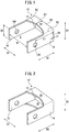
- FIG. 1 is a perspective view showing a suspension link bracket 10 as one example of a joint according to an embodiment of the present invention.
- the bracket 10 is comprised of a base part 12, a pair of side parts 14, 14, and a closed part 16.
- the base part 12 is attached to a component of the suspension link comprised of a not shown rod. Note that when attaching the base part 12 to the rod, it may be attached to just one end of the rod of course and may be attached to the two ends of the rod.
- the pair of side parts 14, 14 extend from the two end parts of the base part 12 in the first direction D1 to the same side in a second direction D2 vertical to the first direction D1 (in FIG. 1 , bottom left side) while connected to the base part 12. Further, the pair of side parts 14, 14 are formed with fastening holes 14H, 14H at the center parts in the third direction D3.
- the fastening holes 14H are bolt holes for bolting in a state with, for example, bushes (not shown) held inside the bracket 10.
- the closed part 16 is formed between the pair of side parts 14, 14 and at least at one end part in the third direction D3 (in FIG. 1 , only the top end part) as an extended region of the base part 12 and pair of side parts 14, 14.
- the "as an extended region” means the closed part 16 is attached to the base part 12 and the side parts 14 by bonding, welding, or other various connecting methods of course and also including the members 12, 14, and 16 being produced from the same material.
- ridgeline parts R1 are formed at the boundary parts of the base part 12 and the side parts 14, 14. Further, at the boundary parts of the side parts 14, 14 and the closed part 16, ridgeline parts R2 are formed. Furthermore, at the boundary part of the closed part 16 and the base part 12, a ridgeline part R3 is formed.
- the suspension link bracket 10 of the thus configured embodiment since the closed part 16 is formed between the above described pair of side parts 14, 14, it is possible to suppress out-of-plane deformation of the pair of side parts 14, 14 to the first direction D1 due to force applied from the wheels etc. As a result, according to the suspension link bracket 10 of the present embodiment, it is possible to realize a higher rigidity without uniformly increasing the wall thickness.
- the length L1 from a base part side end part of the side parts 14, 14 shown in FIG. 1 in the second direction D2 to a center position of a fastening hole and the smallest length L2 of the closed part 16 in the second direction D2 preferably satisfy the relationship of 0.1 ⁇ L 1 ⁇ L 2 ⁇ 1.0 ⁇ L 1
- bracket rigidity value is the value defined by the ratio of the load (kN) applied in the first direction D1 of the bracket shown in FIG. 1 and the amount of displacement (mm) of a side part 14 in the second direction D2 due to the same.
- Table 1 shows the results of calculation relating to the relationship of the ratio (L2/L1) and the bracket rigidity value (kN/mm).
- Table 1 L2/L1 0 0.05 0.1 0.15 0.2 0.25 Bracket rigidity value (kN/mm) 68.9 70.3 74.8 80.8 86.3 91.2 L2/L1 0.3 0.4 0.5 0.6 0.7 0.8 Bracket rigidity value (kN/mm) 94.3 98.6 100.5 101.7 102.5 103.0
- this effect is exhibited at a higher level by making 0.3 ⁇ L1 ⁇ L2. If making 0.4 ⁇ L1 ⁇ L2, it is exhibited at a still higher level, while if making 0.5 ⁇ L1 ⁇ L2, it is exhibited at an extremely high level.
- the smallest length L2 smaller than 0.8X the length L1
- the bracket 10 comprised of the base part 12, pair of side parts 14, 14, and closed part 16 can be formed by not only welding the parts 12, 14, and 1 together, but also by one-piece molding. For this reason, the smallest length L2 is made smaller than 0.6X the length L1 so as to increase the degree of freedom of design.
- the radius of curvature of the inner circumferential surface r1 of the boundary part R1 between the base part 12 and the side parts 14, the radius of curvature of the inner circumferential surface r2 of the boundary part R2 of the side parts 14 and the closed part 16, the radius of curvature of the inner circumferential surface r3 of the boundary part R3 between the closed part 16 and the base part 12, the dimension W1 between the pair of side parts 14, 14 in the first direction D1, and the dimension W3 in the third direction D3 of the base part 12 preferably respectively satisfy the relationships of r 1 ⁇ 0.1 ⁇ W 1 and r 1 ⁇ 0.1 ⁇ W 3 r 2 ⁇ 0.1 ⁇ W 1 and r 2 ⁇ 0.1 ⁇ W 3 r 3 ⁇ 0.1 ⁇ W 1 and r 3 ⁇ 0.1 ⁇ W 3
- the space S in the bracket 10 for example, a bushing or other part is held. For this reason, the space S has to have a certain extent of volume. If one or more of any of the radii of curvature of the inner circumferential surface r1, r2, and r3 of the ridgeline parts R1, R2, and R3 are excessively large, the space S becomes smaller by that amount and the possibility of contact with a part held in the bracket 10 becomes higher. To avoid this contact, it may be considered to make the length L1 larger to sufficiently secure the space S, but an increase of the length L1, as explained above, invites a drop in the rigidity of the bracket 10, so is not preferable.
- bracket 10 comprised of the base part 12, pair of side parts 14, 14, and closed part 16 not only by welding the parts 12, 14, 1 together, but also by one-piece molding. For this reason, when satisfying all of the above relation (4) to relation (6), the freedom of design increases.
- the thickness t1 of the base part 12 and the thickness t2 of the closed part 16 preferably satisfy the relation t 2 > t 1
- the bracket 10 shown in FIG. 1 can be formed without welding etc. by working a single material (metal sheet).
- metal sheet metal sheet
- the sheet thickness of the drawn part of the metal sheet decreases compared with the thickness of the other parts.
- the closed part 16 of the bracket 10 of the embodiment obtained by one-piece molding is obtained by so-called "shrink flanging".
- a part worked by shrink flanging becomes greater in thickness than before working. For this reason, for example, if comparing the thickness t1 of the base part 12 and the thickness t2 of the closed part 16 which were worked from a member of the originally same thickness, t2>t1 stand.
- the bracket 10 of the present embodiment obtained by one-piece molding by satisfying the relation (7), it is possible to sufficiently secure the thickness of the closed part 16. As a result, it is possible to further suppress out-of-plane deformation of the side parts 14, 14 in the first direction D1 and in turn possible to further raise the rigidity of the bracket 10 as a whole.
- the closed part 16 is formed at one side of the side parts 14 in the third direction D3, but as shown in the example shown in FIG. 2 (perspective view showing modification of bracket shown in FIG. 1 ), preferably the closed part 16 is formed at the two end parts in the third direction D3.
- component elements the same as the example shown in FIG. 1 are assigned the same reference notations.
- a pair of closed parts 16, 16 differing in position in the third direction D3 are formed between the pair of side parts 14, 14. That is, the closed parts 16, 16 are formed at the top end part and bottom end part of the pair of side parts 14, 14 in the third direction D3 as extended regions of the base part 12 and pair of side parts 14, 14.
- the joint is formed by one-piece molding.
- the first direction D1, second direction D2, and third direction D3 used in the following explanation of the method of production are the same directions as the directions D1, D2, and D3 used in the above section on the suspension link bracket.
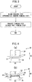
- FIG. 3 is a flow chart showing the procedure of the method of production of a joint according to an embodiment of the present invention (suspension link bracket). As shown in the figure, the method of production of a joint according to the present embodiment includes a blank bending step and a bracket forming step.
- the blank used as the material of the bracket may be made of any known material so long as a metal sheet.
- a steel sheet high strength steel sheet
- stainless steel sheet stainless steel sheet
- surface-treated steel sheet hot dip galvanized steel sheet, zinc-aluminum plated steel sheet, etc.
- nonferrous metal sheet aluminum alloy sheet and titanium sheet etc.
- This step is a step of bending at least one end part of a work, that is, a blank, in the third direction to one side in the second direction to form an intermediate member of an upside-down L-shape or upside-down U-shape when viewed by a side view.
- FIGS. 4(a) and 4(b) are side views showing an apparatus 20 used in the blank bending step. In the figure, FIG. 4(a) shows the state before bending, while FIG. 4(b) shows the state at the time of end of bending. Note that, the example shown in FIGS.
- 4(a) and 4(b) is an example of bending the two end parts in the third direction of a blank comprised of a metal sheet to one side in the second direction to form an intermediate member of an upside-down U-shape when seen by a side view.
- the apparatus 20 is a press-forming apparatus for bending provided with a die 24 to which a pad 22 is attached movably in the clamping direction and a punch 26.
- the blank X1 is set at the apparatus 20, then the blank X1 is clamped between the pad 22 attached to the die 24 to be able to move in the clamping direction (second direction D2) and the punch 26.
- the die 24 is made to descend whereby the two end parts of the blank X1 in the third direction D3 are bent by the die 24 to one side in the second direction D2 (in the figure, the lower side). Due to this, an intermediate member X2 of an upside-down U-shape when viewed by a side view having a main body X21 (corresponding to mainly base part 12 and side parts 14 of FIG. 1 ) and a pair of flanges X22, X22 connected to the main body X21 (corresponding to mainly closed part 16 of FIG. 1 ) is obtained.
- This step is a step of bending the two end parts in the first direction D1 of the intermediate member X2 obtained in the blank bending step to the one side in the second direction (that is, the side bending the two end parts of the blank in the third direction in the blank bending step).
- FIG. 5 is a perspective view showing an apparatus used in the bracket forming step.
- the apparatus 30, as shown in FIG. 5 is provided with a die 32 constraining and holding the two end parts of the intermediate member X2 in the first direction D1, a blank holder 34, a punch 36, a pad 38 supported at the die 32 to be able to move in the clamping direction, and an inner pad 40 supported at the punch 36 to be able to move in the clamping direction and further is provided with an out-of-plane deformation suppressing tool 42 arranged facing a side surface 36a of the punch 36.
- the die 32, blank holder 34, punch 36, pad 38, inner pad 40, and out-of-plane deformation suppressing tool 42 used may all be of any types so long as ones used in general press-forming apparatuses using drawing operations etc.
- the intermediate member X2 is set on these members 34, 40.
- the flanges X22, X22 are positioned at the further outside in the third direction D3 from the two outermost parts of the members 34, 36, and 40 in the same direction D3 so that only the main body X21 contacts the top surface of the blank holder 34 and the top surface of the inner pad 40.
- the out-of-plane deformation suppressing tool 42 is arranged facing the side surface 36a of the punch 36 considering a predetermined clearance from the side surface 36a.
- the pad 38 attached to be able to move with respect to the die 32 in the clamping direction (second direction D2) and the blank holder 34 and inner pad 40 are used to clamp the intermediate member X2.
- the die 32 move to one side in the second direction D2 (lower side of FIG. 5 ) (descend), the two end parts of the intermediate member X2 in the first direction D1 are bent by the die 32 to one side in the second direction D2 (lower side of FIG. 5 ).
- the inner pad 40 also descends.
- the two end parts of the intermediate member X2 in the first direction D1 are bent to their final positions.
- the bent parts in the intermediate member X2 become mainly the side parts 14 of FIG. 1
- the unbent part becomes mainly the base part 12 of FIG. 1 . Due to the above, a bracket of a predetermined shape shown in FIG. 1 provided with a base part 12, side parts 14, 14, and closed part 16 is obtained.
- Such a bracket is increased in thickness at the closed part 16 worked by shrink flanging from the base part 12 or the side parts 14, 14.
- the thickness of the closed part 16 becomes larger than the thickness of the base part 12 or the thicknesses of the side parts 14, 14. Therefore, in the method of production of a suspension link bracket according to the present invention, it is possible to increase the rigidity without uniformly increasing the wall thickness of the bracket itself by the form of the closed part (increase in thickness) between the pair of side parts.
- a high strength steel sheet (thickness: 3.0 mm, grade: 440 MPa class) was used to prepare suspension link brackets by various methods. The effects of their structures (presence of closed part) on the bracket rigidity were evaluated.
- a suspension link bracket of the Invention Example A was prepared using the apparatus shown in FIGS. 4(a) and 4(b) and FIG. 5 by a predetermined method of production of the present application (including steps shown in FIG. 3 ). Further, a conventional apparatus was used to shape parts of the suspension link bracket shown in FIG. 1 other than the closed part 16, a closed part 16 was separately prepared, and then these were welded together to prepare the bracket of Invention Example B. As opposed to this, an ordinary press machine was used to shape the parts of the suspension link bracket shown in FIG. 1 other than the closed part 16 to obtain a bracket of Conventional Example 1 not provided with a closed part.
- suspension link brackets were prepared by the conventional method and one-piece molding method of the present application.
- suspension link brackets of Invention Example 1 and Invention Example 3 shown in FIG. 1 or FIG. 2 were prepared by a predetermined method of production of the present application (including steps shown in FIG. 3 ). Further, using a usual press machine, the parts other than the closed part 16 of the suspension link bracket shown in FIG. 1 were formed to prepare a suspension link bracket of Conventional Example 2 not provided with a closed part. Further, the suspension link bracket of Invention Example 2 is comprised of the suspension link bracket of Conventional Example 2 to which a closed part of a sheet thickness of 3.3 mm is joined by welding. Note that, the other design conditions of the bracket structure of each test example were as shown in the following Table 3.
- the bracket of each of the test examples was bolted using the pair of fastening holes 14H shown in FIG. 1 to fasten the base part 12 in place.
- the pair of side parts 14, 14 were given a 10 kN compressive force in the second direction D2.
- the amount of displacement of a center of a fastening hole14H in the second direction D2 was measured.
- the value of the compressive force divided by the displacement was calculated as the rigidity value. The results are described together in Table 3.
Landscapes
- Engineering & Computer Science (AREA)
- Mechanical Engineering (AREA)
- Vehicle Body Suspensions (AREA)
- Bending Of Plates, Rods, And Pipes (AREA)
- Body Structure For Vehicles (AREA)
- Rolling Contact Bearings (AREA)
Applications Claiming Priority (2)
| Application Number | Priority Date | Filing Date | Title |
|---|---|---|---|
| JP2014209256 | 2014-10-10 | ||
| PCT/JP2015/078523 WO2016056601A1 (fr) | 2014-10-10 | 2015-10-07 | Coupleur |
Publications (3)
| Publication Number | Publication Date |
|---|---|
| EP3205519A1 true EP3205519A1 (fr) | 2017-08-16 |
| EP3205519A4 EP3205519A4 (fr) | 2018-06-27 |
| EP3205519B1 EP3205519B1 (fr) | 2023-05-10 |
Family
ID=55653207
Family Applications (1)
| Application Number | Title | Priority Date | Filing Date |
|---|---|---|---|
| EP15849245.4A Active EP3205519B1 (fr) | 2014-10-10 | 2015-10-07 | Procede de production d'un coupleur |
Country Status (10)
| Country | Link |
|---|---|
| US (1) | US10518596B2 (fr) |
| EP (1) | EP3205519B1 (fr) |
| JP (1) | JP6515352B2 (fr) |
| KR (1) | KR101998491B1 (fr) |
| CN (1) | CN106794733B (fr) |
| BR (1) | BR112017006843A2 (fr) |
| CA (1) | CA2963632A1 (fr) |
| MX (1) | MX2017004487A (fr) |
| RU (1) | RU2668788C1 (fr) |
| WO (1) | WO2016056601A1 (fr) |
Families Citing this family (18)
| Publication number | Priority date | Publication date | Assignee | Title |
|---|---|---|---|---|
| JP6570989B2 (ja) * | 2015-12-09 | 2019-09-04 | 日本製鉄株式会社 | サスペンションのコントロールアーム |
| DE102016109184B4 (de) * | 2016-05-19 | 2018-12-13 | Saf-Holland Gmbh | Haltebock |
| US20180238041A1 (en) | 2017-02-21 | 2018-08-23 | Styrc Jacek | Modular furniture system |
| JP6863207B2 (ja) * | 2017-09-29 | 2021-04-21 | トヨタ自動車株式会社 | ロアアーム支持ブラケット及びこれを備えるロアアーム支持機構 |
| USD887025S1 (en) | 2017-11-17 | 2020-06-09 | 2724889 Ontario Inc. | Connector for a modular structure |
| USD952384S1 (en) | 2020-02-04 | 2022-05-24 | 2724889 Ontario Inc. | Leg |
| USD938771S1 (en) * | 2020-02-04 | 2021-12-21 | 2724889 Ontario Inc. | Connector |
| USD938770S1 (en) * | 2020-02-04 | 2021-12-21 | 2724889 Ontario Inc. | Connector |
| USD952382S1 (en) | 2020-02-04 | 2022-05-24 | 2724889 Ontario Inc. | Table |
| USD938772S1 (en) * | 2020-02-04 | 2021-12-21 | 2724889 Ontario Inc. | Connector |
| USD936859S1 (en) | 2020-02-04 | 2021-11-23 | 2724889 Ontario Inc. | Connector |
| USD936861S1 (en) | 2020-08-12 | 2021-11-23 | 2724889 Ontario Inc. | Connector for a modular structure |
| USD939106S1 (en) | 2020-08-12 | 2021-12-21 | 2724889 Ontario Inc. | Connector for a modular structure |
| USD938068S1 (en) | 2020-08-12 | 2021-12-07 | 2724889 Ontario Inc. | Connector for a modular structure |
| USD936247S1 (en) | 2020-08-12 | 2021-11-16 | 2724889 Ontario Inc. | Connector for a modular structure |
| USD936246S1 (en) | 2020-08-12 | 2021-11-16 | 2724889 Ontario Inc. | Connector for a modular structure |
| USD939731S1 (en) | 2020-08-12 | 2021-12-28 | 2724889 Ontario Inc. | Connector for a modular structure |
| USD938619S1 (en) | 2020-08-12 | 2021-12-14 | 2724889 Ontario Inc. | Connector for a modular structure |
Family Cites Families (22)
| Publication number | Priority date | Publication date | Assignee | Title |
|---|---|---|---|---|
| US4034946A (en) * | 1976-08-24 | 1977-07-12 | N. A. Taylor Co. Inc. | Mounting device for lights |
| JPH0686164B2 (ja) * | 1985-09-05 | 1994-11-02 | 本田技研工業株式会社 | 多リンク式トレ−リングア−ム型サスペンシヨン |
| US5301977A (en) * | 1992-11-02 | 1994-04-12 | Specialty Products Company | Method and apparatus for adjusting toe and/or camber |
| US5775719A (en) * | 1997-03-21 | 1998-07-07 | General Motors Corporation | Control arm alignment mechanism |
| KR19980061526U (ko) * | 1997-03-26 | 1998-11-05 | 김영귀 | 팬하드 브라켓 |
| JP3393980B2 (ja) * | 1997-07-17 | 2003-04-07 | プレス工業株式会社 | ブラケット構造 |
| JP4146009B2 (ja) | 1998-10-05 | 2008-09-03 | プレス工業株式会社 | リーフ式サスペンションブラケット |
| US6536179B2 (en) * | 2001-02-16 | 2003-03-25 | John M. Little | Blocking anchor for attachment of a bridge between adjacent floor joists |
| US6808333B2 (en) * | 2002-10-30 | 2004-10-26 | Cnh Canada, Ltd | Pivot pin assembly |
| US7360774B2 (en) * | 2004-08-11 | 2008-04-22 | Arvinmeritor Technology, Llc | Cast trailing arm assembly for trailer suspension |
| JP4589775B2 (ja) * | 2005-03-24 | 2010-12-01 | スズキ株式会社 | サスペンションロッド及びその製造方法 |
| JP4856411B2 (ja) * | 2005-09-15 | 2012-01-18 | アイシン軽金属株式会社 | サスペンションリンク |
| JP2007076615A (ja) * | 2005-09-16 | 2007-03-29 | Toyota Motor Corp | サスペンションアーム |
| JP2009184460A (ja) * | 2008-02-05 | 2009-08-20 | Showa Denko Kk | 車両用リンク部品 |
| JP5201342B2 (ja) | 2008-09-24 | 2013-06-05 | トヨタ自動車株式会社 | 車両用i型サスペンションアーム |
| JP2012188076A (ja) | 2011-03-14 | 2012-10-04 | Yorozu Corp | 車両用のアーム部品とその製造方法 |
| RU2570208C2 (ru) * | 2011-05-17 | 2015-12-10 | Армстронг Уорлд Индастриз, Инк. | Крепежное приспособление и крепежная система для вертикальных панелей |
| KR20150016537A (ko) * | 2012-06-08 | 2015-02-12 | 신닛테츠스미킨 카부시키카이샤 | 연결 구조, 연결 구조를 갖는 연결 부재 및 연결 구조를 갖는 연결 부재의 제조 방법 |
| US9409220B2 (en) * | 2012-11-01 | 2016-08-09 | Coulter Ventures, LLC | Exercise equipment, connector or anchor, and method of making same |
| JP5569609B1 (ja) * | 2013-02-28 | 2014-08-13 | Jfeスチール株式会社 | プレス成形方法 |
| CA2901744C (fr) * | 2013-03-21 | 2017-11-21 | Nippon Steel & Sumitomo Metal Corporation | Procede de production pour element moule par pressage et dispositif de moulage par pressage |
| DE202013103900U1 (de) * | 2013-08-28 | 2013-09-16 | Ford Global Technologies, Llc | Blattfederlager sowie Fahrzeugradaufhängung für ein Fahrzeug mit Querblattfeder |
-
2015
- 2015-10-07 JP JP2016553141A patent/JP6515352B2/ja active Active
- 2015-10-07 KR KR1020177009023A patent/KR101998491B1/ko active IP Right Grant
- 2015-10-07 MX MX2017004487A patent/MX2017004487A/es unknown
- 2015-10-07 WO PCT/JP2015/078523 patent/WO2016056601A1/fr active Application Filing
- 2015-10-07 US US15/517,734 patent/US10518596B2/en active Active
- 2015-10-07 EP EP15849245.4A patent/EP3205519B1/fr active Active
- 2015-10-07 CN CN201580054615.5A patent/CN106794733B/zh active Active
- 2015-10-07 CA CA2963632A patent/CA2963632A1/fr not_active Abandoned
- 2015-10-07 BR BR112017006843A patent/BR112017006843A2/pt not_active Application Discontinuation
- 2015-10-07 RU RU2017115896A patent/RU2668788C1/ru not_active IP Right Cessation
Also Published As
| Publication number | Publication date |
|---|---|
| RU2668788C1 (ru) | 2018-10-02 |
| JP6515352B2 (ja) | 2019-05-22 |
| CN106794733B (zh) | 2019-09-03 |
| EP3205519A4 (fr) | 2018-06-27 |
| JPWO2016056601A1 (ja) | 2017-08-03 |
| US20170305228A1 (en) | 2017-10-26 |
| WO2016056601A1 (fr) | 2016-04-14 |
| CA2963632A1 (fr) | 2016-04-14 |
| EP3205519B1 (fr) | 2023-05-10 |
| CN106794733A (zh) | 2017-05-31 |
| KR101998491B1 (ko) | 2019-07-09 |
| KR20170048538A (ko) | 2017-05-08 |
| MX2017004487A (es) | 2017-06-19 |
| BR112017006843A2 (pt) | 2017-12-12 |
| US10518596B2 (en) | 2019-12-31 |
Similar Documents
| Publication | Publication Date | Title |
|---|---|---|
| EP3205519B1 (fr) | Procede de production d'un coupleur | |
| KR101472645B1 (ko) | L자 형상을 갖는 부품의 프레스 성형 방법 | |
| US10596613B2 (en) | Producing method, producing apparatus and producing equipment line of press formed product | |
| US20160288186A1 (en) | Blank steel plate, production method and production device therefor, and production method for press-formed product using blank steel plate | |
| EP3572256B1 (fr) | Faisceau de porte | |
| US10202012B2 (en) | Suspension link and production method therefor | |
| KR101947938B1 (ko) | 구조 부재 | |
| EP3037188B1 (fr) | Procédé pour la fabrication d'un élément structural pour une carrosserie d'automobile et dispositif de moulage par compression | |
| CN104254453A (zh) | 车辆用悬挂臂 | |
| EP3489055A1 (fr) | Faisceau de porte | |
| EP3251770B1 (fr) | Produit de formage ainsi que procédé et ligne de production pour la fabrication d'un tel produit de formage | |
| JP2020121336A (ja) | 車両構造部材を製造する方法 | |
| JP2020121690A (ja) | 車両構造部材 | |
| EP3702059A1 (fr) | Composant d'alliage d'aluminium | |
| JP4734129B2 (ja) | 衝突特性に優れた自動車用強度部材 | |
| EP3932750B1 (fr) | Élément structural pour véhicule |
Legal Events
| Date | Code | Title | Description |
|---|---|---|---|
| STAA | Information on the status of an ep patent application or granted ep patent |
Free format text: STATUS: THE INTERNATIONAL PUBLICATION HAS BEEN MADE |
|
| PUAI | Public reference made under article 153(3) epc to a published international application that has entered the european phase |
Free format text: ORIGINAL CODE: 0009012 |
|
| STAA | Information on the status of an ep patent application or granted ep patent |
Free format text: STATUS: REQUEST FOR EXAMINATION WAS MADE |
|
| 17P | Request for examination filed |
Effective date: 20170509 |
|
| AK | Designated contracting states |
Kind code of ref document: A1 Designated state(s): AL AT BE BG CH CY CZ DE DK EE ES FI FR GB GR HR HU IE IS IT LI LT LU LV MC MK MT NL NO PL PT RO RS SE SI SK SM TR |
|
| AX | Request for extension of the european patent |
Extension state: BA ME |
|
| DAV | Request for validation of the european patent (deleted) | ||
| DAX | Request for extension of the european patent (deleted) | ||
| RIC1 | Information provided on ipc code assigned before grant |
Ipc: B21D 53/88 20060101ALI20180517BHEP Ipc: B60G 7/00 20060101AFI20180517BHEP |
|
| A4 | Supplementary search report drawn up and despatched |
Effective date: 20180528 |
|
| RIC1 | Information provided on ipc code assigned before grant |
Ipc: B60G 7/00 20060101AFI20180522BHEP Ipc: B21D 53/88 20060101ALI20180522BHEP |
|
| RAP1 | Party data changed (applicant data changed or rights of an application transferred) |
Owner name: NIPPON STEEL CORPORATION |
|
| STAA | Information on the status of an ep patent application or granted ep patent |
Free format text: STATUS: EXAMINATION IS IN PROGRESS |
|
| 17Q | First examination report despatched |
Effective date: 20191212 |
|
| STAA | Information on the status of an ep patent application or granted ep patent |
Free format text: STATUS: EXAMINATION IS IN PROGRESS |
|
| STAA | Information on the status of an ep patent application or granted ep patent |
Free format text: STATUS: EXAMINATION IS IN PROGRESS |
|
| GRAP | Despatch of communication of intention to grant a patent |
Free format text: ORIGINAL CODE: EPIDOSNIGR1 |
|
| STAA | Information on the status of an ep patent application or granted ep patent |
Free format text: STATUS: GRANT OF PATENT IS INTENDED |
|
| INTG | Intention to grant announced |
Effective date: 20230112 |
|
| GRAS | Grant fee paid |
Free format text: ORIGINAL CODE: EPIDOSNIGR3 |
|
| GRAA | (expected) grant |
Free format text: ORIGINAL CODE: 0009210 |
|
| STAA | Information on the status of an ep patent application or granted ep patent |
Free format text: STATUS: THE PATENT HAS BEEN GRANTED |
|
| AK | Designated contracting states |
Kind code of ref document: B1 Designated state(s): AL AT BE BG CH CY CZ DE DK EE ES FI FR GB GR HR HU IE IS IT LI LT LU LV MC MK MT NL NO PL PT RO RS SE SI SK SM TR |
|
| REG | Reference to a national code |
Ref country code: GB Ref legal event code: FG4D |
|
| REG | Reference to a national code |
Ref country code: AT Ref legal event code: REF Ref document number: 1566353 Country of ref document: AT Kind code of ref document: T Effective date: 20230515 Ref country code: CH Ref legal event code: EP |
|
| REG | Reference to a national code |
Ref country code: DE Ref legal event code: R096 Ref document number: 602015083555 Country of ref document: DE |
|
| REG | Reference to a national code |
Ref country code: IE Ref legal event code: FG4D |
|
| REG | Reference to a national code |
Ref country code: LT Ref legal event code: MG9D |
|
| REG | Reference to a national code |
Ref country code: NL Ref legal event code: MP Effective date: 20230510 |
|
| REG | Reference to a national code |
Ref country code: AT Ref legal event code: MK05 Ref document number: 1566353 Country of ref document: AT Kind code of ref document: T Effective date: 20230510 |
|
| PG25 | Lapsed in a contracting state [announced via postgrant information from national office to epo] |
Ref country code: SE Free format text: LAPSE BECAUSE OF FAILURE TO SUBMIT A TRANSLATION OF THE DESCRIPTION OR TO PAY THE FEE WITHIN THE PRESCRIBED TIME-LIMIT Effective date: 20230510 Ref country code: PT Free format text: LAPSE BECAUSE OF FAILURE TO SUBMIT A TRANSLATION OF THE DESCRIPTION OR TO PAY THE FEE WITHIN THE PRESCRIBED TIME-LIMIT Effective date: 20230911 Ref country code: NO Free format text: LAPSE BECAUSE OF FAILURE TO SUBMIT A TRANSLATION OF THE DESCRIPTION OR TO PAY THE FEE WITHIN THE PRESCRIBED TIME-LIMIT Effective date: 20230810 Ref country code: NL Free format text: LAPSE BECAUSE OF FAILURE TO SUBMIT A TRANSLATION OF THE DESCRIPTION OR TO PAY THE FEE WITHIN THE PRESCRIBED TIME-LIMIT Effective date: 20230510 Ref country code: ES Free format text: LAPSE BECAUSE OF FAILURE TO SUBMIT A TRANSLATION OF THE DESCRIPTION OR TO PAY THE FEE WITHIN THE PRESCRIBED TIME-LIMIT Effective date: 20230510 Ref country code: AT Free format text: LAPSE BECAUSE OF FAILURE TO SUBMIT A TRANSLATION OF THE DESCRIPTION OR TO PAY THE FEE WITHIN THE PRESCRIBED TIME-LIMIT Effective date: 20230510 |
|
| PG25 | Lapsed in a contracting state [announced via postgrant information from national office to epo] |
Ref country code: RS Free format text: LAPSE BECAUSE OF FAILURE TO SUBMIT A TRANSLATION OF THE DESCRIPTION OR TO PAY THE FEE WITHIN THE PRESCRIBED TIME-LIMIT Effective date: 20230510 Ref country code: PL Free format text: LAPSE BECAUSE OF FAILURE TO SUBMIT A TRANSLATION OF THE DESCRIPTION OR TO PAY THE FEE WITHIN THE PRESCRIBED TIME-LIMIT Effective date: 20230510 Ref country code: LV Free format text: LAPSE BECAUSE OF FAILURE TO SUBMIT A TRANSLATION OF THE DESCRIPTION OR TO PAY THE FEE WITHIN THE PRESCRIBED TIME-LIMIT Effective date: 20230510 Ref country code: LT Free format text: LAPSE BECAUSE OF FAILURE TO SUBMIT A TRANSLATION OF THE DESCRIPTION OR TO PAY THE FEE WITHIN THE PRESCRIBED TIME-LIMIT Effective date: 20230510 Ref country code: IS Free format text: LAPSE BECAUSE OF FAILURE TO SUBMIT A TRANSLATION OF THE DESCRIPTION OR TO PAY THE FEE WITHIN THE PRESCRIBED TIME-LIMIT Effective date: 20230910 Ref country code: HR Free format text: LAPSE BECAUSE OF FAILURE TO SUBMIT A TRANSLATION OF THE DESCRIPTION OR TO PAY THE FEE WITHIN THE PRESCRIBED TIME-LIMIT Effective date: 20230510 Ref country code: GR Free format text: LAPSE BECAUSE OF FAILURE TO SUBMIT A TRANSLATION OF THE DESCRIPTION OR TO PAY THE FEE WITHIN THE PRESCRIBED TIME-LIMIT Effective date: 20230811 |
|
| PGFP | Annual fee paid to national office [announced via postgrant information from national office to epo] |
Ref country code: FR Payment date: 20230901 Year of fee payment: 9 |
|
| PG25 | Lapsed in a contracting state [announced via postgrant information from national office to epo] |
Ref country code: FI Free format text: LAPSE BECAUSE OF FAILURE TO SUBMIT A TRANSLATION OF THE DESCRIPTION OR TO PAY THE FEE WITHIN THE PRESCRIBED TIME-LIMIT Effective date: 20230510 |
|
| PG25 | Lapsed in a contracting state [announced via postgrant information from national office to epo] |
Ref country code: SK Free format text: LAPSE BECAUSE OF FAILURE TO SUBMIT A TRANSLATION OF THE DESCRIPTION OR TO PAY THE FEE WITHIN THE PRESCRIBED TIME-LIMIT Effective date: 20230510 |
|
| PG25 | Lapsed in a contracting state [announced via postgrant information from national office to epo] |
Ref country code: SM Free format text: LAPSE BECAUSE OF FAILURE TO SUBMIT A TRANSLATION OF THE DESCRIPTION OR TO PAY THE FEE WITHIN THE PRESCRIBED TIME-LIMIT Effective date: 20230510 Ref country code: SK Free format text: LAPSE BECAUSE OF FAILURE TO SUBMIT A TRANSLATION OF THE DESCRIPTION OR TO PAY THE FEE WITHIN THE PRESCRIBED TIME-LIMIT Effective date: 20230510 Ref country code: RO Free format text: LAPSE BECAUSE OF FAILURE TO SUBMIT A TRANSLATION OF THE DESCRIPTION OR TO PAY THE FEE WITHIN THE PRESCRIBED TIME-LIMIT Effective date: 20230510 Ref country code: EE Free format text: LAPSE BECAUSE OF FAILURE TO SUBMIT A TRANSLATION OF THE DESCRIPTION OR TO PAY THE FEE WITHIN THE PRESCRIBED TIME-LIMIT Effective date: 20230510 Ref country code: DK Free format text: LAPSE BECAUSE OF FAILURE TO SUBMIT A TRANSLATION OF THE DESCRIPTION OR TO PAY THE FEE WITHIN THE PRESCRIBED TIME-LIMIT Effective date: 20230510 Ref country code: CZ Free format text: LAPSE BECAUSE OF FAILURE TO SUBMIT A TRANSLATION OF THE DESCRIPTION OR TO PAY THE FEE WITHIN THE PRESCRIBED TIME-LIMIT Effective date: 20230510 |
|
| PGFP | Annual fee paid to national office [announced via postgrant information from national office to epo] |
Ref country code: DE Payment date: 20231027 Year of fee payment: 9 |
|
| REG | Reference to a national code |
Ref country code: DE Ref legal event code: R097 Ref document number: 602015083555 Country of ref document: DE |
|
| PLBE | No opposition filed within time limit |
Free format text: ORIGINAL CODE: 0009261 |
|
| STAA | Information on the status of an ep patent application or granted ep patent |
Free format text: STATUS: NO OPPOSITION FILED WITHIN TIME LIMIT |
|
| 26N | No opposition filed |
Effective date: 20240213 |
|
| PG25 | Lapsed in a contracting state [announced via postgrant information from national office to epo] |
Ref country code: SI Free format text: LAPSE BECAUSE OF FAILURE TO SUBMIT A TRANSLATION OF THE DESCRIPTION OR TO PAY THE FEE WITHIN THE PRESCRIBED TIME-LIMIT Effective date: 20230510 |