EP3204657B1 - Snap hook - Google Patents
Snap hook Download PDFInfo
- Publication number
- EP3204657B1 EP3204657B1 EP15785204.7A EP15785204A EP3204657B1 EP 3204657 B1 EP3204657 B1 EP 3204657B1 EP 15785204 A EP15785204 A EP 15785204A EP 3204657 B1 EP3204657 B1 EP 3204657B1
- Authority
- EP
- European Patent Office
- Prior art keywords
- trigger
- link
- gate
- snap hook
- body plate
- Prior art date
- Legal status (The legal status is an assumption and is not a legal conclusion. Google has not performed a legal analysis and makes no representation as to the accuracy of the status listed.)
- Active
Links
- 230000004913 activation Effects 0.000 claims description 4
- 230000008878 coupling Effects 0.000 claims description 2
- 238000010168 coupling process Methods 0.000 claims description 2
- 238000005859 coupling reaction Methods 0.000 claims description 2
- 230000007246 mechanism Effects 0.000 description 4
- 230000009471 action Effects 0.000 description 3
- 125000006850 spacer group Chemical group 0.000 description 3
- 238000005452 bending Methods 0.000 description 2
- 230000008901 benefit Effects 0.000 description 2
- 239000000463 material Substances 0.000 description 2
- 239000006096 absorbing agent Substances 0.000 description 1
- 230000006978 adaptation Effects 0.000 description 1
- 230000000881 depressing effect Effects 0.000 description 1
- 230000000994 depressogenic effect Effects 0.000 description 1
- 238000000034 method Methods 0.000 description 1
- 230000008569 process Effects 0.000 description 1
Images


Classifications
-
- A—HUMAN NECESSITIES
- A62—LIFE-SAVING; FIRE-FIGHTING
- A62B—DEVICES, APPARATUS OR METHODS FOR LIFE-SAVING
- A62B35/00—Safety belts or body harnesses; Similar equipment for limiting displacement of the human body, especially in case of sudden changes of motion
- A62B35/0006—Harnesses; Accessories therefor
- A62B35/0025—Details and accessories
- A62B35/0037—Attachments for lifelines and lanyards
-
- F—MECHANICAL ENGINEERING; LIGHTING; HEATING; WEAPONS; BLASTING
- F16—ENGINEERING ELEMENTS AND UNITS; GENERAL MEASURES FOR PRODUCING AND MAINTAINING EFFECTIVE FUNCTIONING OF MACHINES OR INSTALLATIONS; THERMAL INSULATION IN GENERAL
- F16B—DEVICES FOR FASTENING OR SECURING CONSTRUCTIONAL ELEMENTS OR MACHINE PARTS TOGETHER, e.g. NAILS, BOLTS, CIRCLIPS, CLAMPS, CLIPS OR WEDGES; JOINTS OR JOINTING
- F16B45/00—Hooks; Eyes
- F16B45/02—Hooks with pivoting or elastically bending closing member
- F16B45/023—Hooks with pivoting or elastically bending closing member the closing member pivoting about an axis perpendicular to the plane of the hook
-
- F—MECHANICAL ENGINEERING; LIGHTING; HEATING; WEAPONS; BLASTING
- F16—ENGINEERING ELEMENTS AND UNITS; GENERAL MEASURES FOR PRODUCING AND MAINTAINING EFFECTIVE FUNCTIONING OF MACHINES OR INSTALLATIONS; THERMAL INSULATION IN GENERAL
- F16B—DEVICES FOR FASTENING OR SECURING CONSTRUCTIONAL ELEMENTS OR MACHINE PARTS TOGETHER, e.g. NAILS, BOLTS, CIRCLIPS, CLAMPS, CLIPS OR WEDGES; JOINTS OR JOINTING
- F16B45/00—Hooks; Eyes
- F16B45/02—Hooks with pivoting or elastically bending closing member
- F16B45/024—Hooks with pivoting or elastically bending closing member and having means biasing the closing member about the pivot
-
- F—MECHANICAL ENGINEERING; LIGHTING; HEATING; WEAPONS; BLASTING
- F16—ENGINEERING ELEMENTS AND UNITS; GENERAL MEASURES FOR PRODUCING AND MAINTAINING EFFECTIVE FUNCTIONING OF MACHINES OR INSTALLATIONS; THERMAL INSULATION IN GENERAL
- F16B—DEVICES FOR FASTENING OR SECURING CONSTRUCTIONAL ELEMENTS OR MACHINE PARTS TOGETHER, e.g. NAILS, BOLTS, CIRCLIPS, CLAMPS, CLIPS OR WEDGES; JOINTS OR JOINTING
- F16B45/00—Hooks; Eyes
- F16B45/02—Hooks with pivoting or elastically bending closing member
- F16B45/027—Hooks with pivoting or elastically bending closing member and having position-locking means for the closing member
- F16B45/028—Hooks with pivoting or elastically bending closing member and having position-locking means for the closing member the position-locking means being pivotally connected
-
- F—MECHANICAL ENGINEERING; LIGHTING; HEATING; WEAPONS; BLASTING
- F16—ENGINEERING ELEMENTS AND UNITS; GENERAL MEASURES FOR PRODUCING AND MAINTAINING EFFECTIVE FUNCTIONING OF MACHINES OR INSTALLATIONS; THERMAL INSULATION IN GENERAL
- F16B—DEVICES FOR FASTENING OR SECURING CONSTRUCTIONAL ELEMENTS OR MACHINE PARTS TOGETHER, e.g. NAILS, BOLTS, CIRCLIPS, CLAMPS, CLIPS OR WEDGES; JOINTS OR JOINTING
- F16B45/00—Hooks; Eyes
- F16B45/02—Hooks with pivoting or elastically bending closing member
- F16B45/037—Multiple locking cavities, each having a pivoting closing member
-
- Y—GENERAL TAGGING OF NEW TECHNOLOGICAL DEVELOPMENTS; GENERAL TAGGING OF CROSS-SECTIONAL TECHNOLOGIES SPANNING OVER SEVERAL SECTIONS OF THE IPC; TECHNICAL SUBJECTS COVERED BY FORMER USPC CROSS-REFERENCE ART COLLECTIONS [XRACs] AND DIGESTS
- Y10—TECHNICAL SUBJECTS COVERED BY FORMER USPC
- Y10T—TECHNICAL SUBJECTS COVERED BY FORMER US CLASSIFICATION
- Y10T24/00—Buckles, buttons, clasps, etc.
- Y10T24/45—Separable-fastener or required component thereof [e.g., projection and cavity to complete interlock]
- Y10T24/45225—Separable-fastener or required component thereof [e.g., projection and cavity to complete interlock] including member having distinct formations and mating member selectively interlocking therewith
- Y10T24/45272—Projection passes through cavity then moves toward noninserted portion of its member to complete interlock [e.g., snap hook]
- Y10T24/45288—Hook type projection member
- Y10T24/45304—Noninserted portion of projection member includes movably connected gate for closing access throat
- Y10T24/45319—Pivotally connected gate
- Y10T24/45335—Pivotally connected gate having means biasing gate about pivot
- Y10T24/4534—Pivotally connected gate having means biasing gate about pivot and position locking-means for gate
-
- Y—GENERAL TAGGING OF NEW TECHNOLOGICAL DEVELOPMENTS; GENERAL TAGGING OF CROSS-SECTIONAL TECHNOLOGIES SPANNING OVER SEVERAL SECTIONS OF THE IPC; TECHNICAL SUBJECTS COVERED BY FORMER USPC CROSS-REFERENCE ART COLLECTIONS [XRACs] AND DIGESTS
- Y10—TECHNICAL SUBJECTS COVERED BY FORMER USPC
- Y10T—TECHNICAL SUBJECTS COVERED BY FORMER US CLASSIFICATION
- Y10T24/00—Buckles, buttons, clasps, etc.
- Y10T24/45—Separable-fastener or required component thereof [e.g., projection and cavity to complete interlock]
- Y10T24/45225—Separable-fastener or required component thereof [e.g., projection and cavity to complete interlock] including member having distinct formations and mating member selectively interlocking therewith
- Y10T24/45272—Projection passes through cavity then moves toward noninserted portion of its member to complete interlock [e.g., snap hook]
- Y10T24/45288—Hook type projection member
- Y10T24/45304—Noninserted portion of projection member includes movably connected gate for closing access throat
- Y10T24/45319—Pivotally connected gate
- Y10T24/45361—Pivotally connected gate having position locking-means for gate
- Y10T24/45366—Locking-means pivotally connected
Landscapes
- Engineering & Computer Science (AREA)
- General Engineering & Computer Science (AREA)
- Mechanical Engineering (AREA)
- Health & Medical Sciences (AREA)
- General Health & Medical Sciences (AREA)
- Business, Economics & Management (AREA)
- Emergency Management (AREA)
- Hooks, Suction Cups, And Attachment By Adhesive Means (AREA)
- Soil Working Implements (AREA)
- Lock And Its Accessories (AREA)
Description
- Various occupations place people in precarious positions at relatively dangerous heights thereby creating a need for fall protection or fall-arresting safety apparatus. For example,
US 2011/094839 (A1 ) discloses an energy absorber comprising an intermediate portion interconnecting a first end and a second end. The intermediate portion and the first and second ends are on the same plane. The intermediate portion includes curved portions configured and arranged to deform and begin to straighten when subjected to a pre-determined load to absorb energy from the pre-determined load. - Furthermore,
US 2011/0175385 A discloses a hook design which provides additional safety features to reduce the potential for accidents and provides additional protection to the operator. The safety design features include a spring activated trigger and latch mechanism, a latch stop, a trigger guard, and a trigger lock mechanism which may or may not utilize a spring to activate it. The safety latching lifting hook provides for ease of connection (hooking) and ease of release (unhooking) with a trigger guard to protect the operator's hand and the trigger latch mechanism. Among other things, such apparatus usually include a safety line interconnection between a support structure and a safety harness donned by a person working in proximity to the support structure. A snap hook is commonly used to connect various components. The snap hook needs to provide its function without failure. - For the reasons stated above and for other reasons stated below which will become apparent to those skilled in the art upon reading and understanding the present specification, there is a need in the art for an improved effective snap hook.
- The above-mentioned problems of current systems are addressed by embodiments of the present invention and will be understood by reading and studying the following specification. The following summary is made by way of example and not by way of limitation. It is merely provided to aid the reader in understanding some of the aspects of the invention.
- In one embodiment, a snap hook is provided. The snap hook includes a body, a gate, a connection link and a breakable fastener. The body has an upper portion, a lower portion and a central portion. The central portion is positioned between the upper portion and the lower portion. The gate is pivotally coupled proximate the central portion of the body. The gate and the body selectively forming a closed configuration that defines a hook connection passage and an open configuration that provides access to the hook connection passage. The connection link has an upper end and a lower end. The upper end of the connection link is pivotally coupled proximate the central portion of the body. The lower end of the connection link includes a body connection aperture. The breakable fastener couples the lower end of the connection link proximate the lower portion of the body. The breakable fastener is configured to break when a select amount of force is applied to the lower end of the connection link to transfer the force from the lower portion of the body to the central portion of the body.
- The present invention can be more easily understood and further advantages and uses thereof will be more readily apparent, when considered in view of the detailed description and the following figures in which:
-
Figure 1A is a first side perspective view of a snap hook of one embodiment of the present invention; -
Figure 1B is a second side perspective view of the snap hook ofFigure 1A ; -
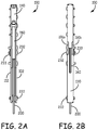
Figure 2A is a front view of the snap hook ofFigure 1A ; -
Figure 2B is a back view of the snap hook ofFigure 1A ; -
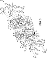
Figure 3 is a partially unassembled side perspective view of the snap hook ofFigure 1A : -
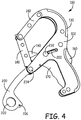
Figure 4 is a side perspective view of the snap hook ofFigure 1A illustrating the pivot function of the connection hook; -
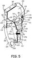
Figure 5 is a side perspective view of a partial snap hook ofFigure 1A ; -
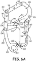
Figure 6A is a side view of a partial snap hook ofFigure 1A in a closed configuration; -
Figure 6B is a side view of the partial snap hook ofFigure 6A at the start of an unlocking process; -
Figure 6C is a side view of the partial snap hook inFigure 6A with the snap hook in an open configuration; -
Figure 6D is a side perspective view of the snap hook ofFigure 1A in an open configuration; and -
Figure 7 is a front perspective view of the snap hook ofFigure 1A after a fall event has occurred. - In accordance with common practice, the various described features are not drawn to scale but are drawn to emphasize specific features relevant to the present invention. Reference characters denote like elements throughout Figures and text.
- In the following detailed description, reference is made to the accompanying drawings, which form a part hereof, and in which is shown by way of illustration specific embodiments in which the inventions may be practiced. These embodiments are described in sufficient detail to enable those skilled in the art to practice the invention, and it is to be understood that other embodiments may be utilized and that changes may be made without departing from the spirit and scope of the present invention. The following detailed description is, therefore, not to be taken in a limiting sense, and the scope of the present invention is defined only by the claims and equivalents thereof.
- Embodiments of the present invention provide a snap hook that includes a pivoting connecting link that reduces bending stress on the hook body during a fall event by redirecting forces initially directed towards the bottom of the snap hook to a more central pivot point. In one embodiment, the connection link is made from a material that is deformable when a select amount of force is encountered, such as but not limited to, forces encountered during the fall event. The deformation absorbs energy and is used indicate the snap hook has been exposed to forces of a certain level and should not be used again. In another embodiment, a connection link is used as a trigger guard to protect a user's hand while connecting and disconnecting the snap hook. Moreover in one embodiment the trigger guard further protects a trigger mechanism from being accidentally actuated. In another embodiment, the snap hook includes an interlocking gate-nose geometry that increases the hook strength while the snap hook is under tensile tension.
- In view of
Figures 1A through 3 , a detailed description of an embodiment of thesnap hook 100 is herein provided. Thesnap hook 100 includes abody 125 that has anupper portion 125a, alower portion 125b and acentral portion 125c that is positioned between theupper portion 125a and thelower portion 125b. Thebody 125 includesfirst body plate 102, asecond body plate 112, anose link 140 and abase member 130. Thefirst body plate 102 and asecond body plate 112 protect internal components of thesnap hook 100. Thefirst body plate 102 has generally an E-shape. Thefirst body plate 102 has an upper end 102a and an opposably positionedlower end 102b as well as afront side 102c and an opposably positionedback side 102d. Thefront side 102c andback side 102d of thefirst body plate 102 respectfully extend from the upper end 102a to thelower end 102b. Thefirst body plate 102 further has a mid-portion 102e that is positioned between the upper end 102a and thelower end 102b. Thefirst body plate 102 includes an upper arm 104a positioned at the upper end 102a of thefirst body plate 102 extending towards thefront side 102c of thefirst body plate 102. The upper arm 104a includes a pair of spacedconnection apertures first body plate 102 also includes alower arm 104b positioned at thelower end 102b of thefirst body plate 102 extending towards thefront side 102c of thefirst body plate 102. Thelower arm 104b includes afuse aperture 108a and aconnection aperture 108b. Theconnection aperture 108b is spaced from thefuse aperture 108a. - The
first body plate 102 further includes a mid-arm 104c that extends from thefront side 102c of thefirst body plate 102 between the upper end 102a and thelower end 102b of thefirst body plate 102 at generally a central location. Proximate a terminal end of the mid-arm 104c is apivot aperture 109 that s positioned proximate a central location of thesnap hook 100. The mid-arm 104c further includes an unlockingslot 110. The unlockingslot 110 in this embodiment has a slight curvature. Proximate the mid-arm 104c in the mid-portion 102e of thefirst body plate 102 is connectingaperture 103 andtrigger aperture 107. Further, thefirst body plate 102 includes an extendingtab 105 that extends from thebackside 102d of thefirst body plate 102 proximate the mid-portion 102e of thefirst body plate 102. - The
second body plate 112 is a mirror image of thefirst body plate 102 in this embodiment. Thesecond body plate 112 has anupper end 112a and an opposably positionedlower end 112b as well as a front side 112c and an opposably positioned backside 112d. The front side 112c and backside 112d of thesecond body plate 112 respectfully extend from theupper end 112a to thelower end 112b. Thesecond body plate 112 further has a mid-portion 112e that is positioned between theupper end 112a and thelower end 112b. Thesecond body plate 112 includes an upper arm 114a positioned at theupper end 112a of thesecond body plate 112 extending towards the front side 112c of thesecond body plate 112. The upper arm 114a includes a pair of spacedconnection apertures first body plate 112 also includes a lower arm 114b positioned at thelower end 112b of thesecond body plate 112 extending towards the front side 112c of thesecond body plate 112. The lower arm 114b includes afuse aperture 118a and aconnection aperture 118b. Theconnection aperture 118b is spaced from thefuse aperture 118a. - The
second body plate 112 further includes a mid-arm 114c that extends from the front side 112c of thesecond body plate 112 between theupper end 112a and thelower end 112b of thesecond body plate 112 at generally central location. Proximate a terminal end of the mid-arm 114c is apivot aperture 119 that is positioned proximate a central location of thesnap hook 100. The mid-arm 114c further includes an unlockingslot 120. The unlockingslot 120 in this embodiment has a slight curvature. Proximate the mid-arm 114c in the mid-portion 112e of thesecond body plate 112 is connectingaperture 113 andtrigger aperture 117. Further, thesecond body plate 112 includes an extendingtab 115 that extends from thebackside 112d of thesecond body plate 112 proximate the mid-portion 112e of thesecond body plate 112. - The
snap hook 100 further includes abase member 130. Thebase member 130 includes anupper end 130a and opposably positionedlower end 130b. Between theupper end 130a and thelower end 130b of thebase member 130 is a mid-portion 130c. Thebase member 130 further includes afront side 130d and an opposably positioned backside 130e. Coupled to theupper end 130a is anose link 140. In particular,fasteners 150 and 151 (such as but not limited to rivets) received inpassages nose link 140 and theupper end 130a of thebase member 130 couple thenose link 140 to thebase member 130. Further, the upper arm 104a of thefirst body plate 102 and the upper arm 114a of thesecond body plate 112 are positioned within thenose link 140 withconnection apertures passages Fasteners passages connection apertures first body plate 102, thenose link 140, thebase member 130 and thesecond body plate 112 together. Thenose link 140 extends from theupper end 130a of thebase member 130 from thefront side 130d of thebase member 130. The nose link 140 further includes a pair of aligned spaced holdingpassages nose link 140. Anose rivet catch 155 is received in the aligned spaced holdingpassages nose link 140. Thebase member 130 further includes alower arm 132 that extends out from thelower end 130b of thebase member 130. Thelower end 130b of thebase member 130 includes a basefront pivot passage 156. The mid-portion 130c of thebase member 130 includes aback trigger slot 136 that extends from thefront side 130d to theback side 130e. Alignedbase pivot passages base member 130. - A
back trigger 160 is partially received within theback trigger slot 136 of thebase member 130. Theback trigger 160 is generally an inverted C-shape in an embodiment. Theback trigger 160 includes an upper back trigger end 160a and an opposably positioned lower back trigger end 160b. Theback trigger 160 further includes a mid-portion 160c positioned between the upper back trigger end 160a and the lower back trigger end 160b and afront side 160d and an opposably positioned back side 160e. Theback trigger 160 further has anupper arm 162 that extends from the upper back trigger end 160a from thefront side 160d and alower arm 164 that extends from the lower back trigger end 160b from thefront side 160d. In addition, theback trigger 160 has a back triggerpivot connection aperture 165 that is posted near the mid-portion and upper back trigger end 160a of theback trigger 160. The back triggerpivot connection aperture 165 is aligned with the alignedbase pivot passages base member 130. A backtrigger pivoting fastener 159 is received in the back triggerpivot connection aperture 165 and the alignedbase pivot passages back trigger 160 to thebase member 130. - A
front trigger 170 that has spaced parallel and mirror imagefront trigger plates 170a and 170b is part of thesnap hook 100. Thefront trigger 170 includes anupper end 172a and an opposably positionedlower end 172b. Thefront trigger 170 further includes afront side 172c and aback side 172d. Thefront side 172c includes an engaging connectingplate 172e that connects thefront trigger plates 170a and 170b together. Thefront side 172c of the trigger in the embodiment shown has an ergonomic shape to aid the user in its activation. Thefront trigger 170 includesguide tabs back side 172d and proximate a mid-portion 172f offront trigger 170. Just below theguide tabs back side 172d of thefront trigger 170 are located biasingseat notches 176a and 176b that are designed to engage a first end of a fronttrigger biasing member 178. Further, proximate theupper end 172a of thefront trigger 170 is a first connection passage 173 that passes through bothfront trigger plates 170a and 170b. Further, a pivot passage 175 located near thelower end 172b of thefront trigger 170 passes through bothfront trigger plates 170a and 170b. - The
snap hook 100 further includes agate 180. Thegate 180 in this embodiment includes spaced parallel and mirror image gate plates 181a and 181b. Thegate 180 includes anupper end 180a and an opposably positioned lower end 180b. Thegate 180 further includes afront side 180c and aback side 180d. Thefront side 180c includes a connectingplate 181c (as best seen in Figure IB) that connects the gate plates 181a and 181b together. Thegate 180 includes agate slot 183 that extends a select distance into thegate 180 from thefront side 180c. Further, thegate slot 183 is located proximate theupper end 180a of thegate 180. The gate slot is designed to receive thenose rivet catch 155 coupled to thenose link 140 when thesnap hook 100 is in the closed configuration. Thenose rivet catch 155 received within thegate slot 183 provides a connection that interlocks thegate 180 proximate thenose link 140. This improves the strength of thesnap hook 100 while thesnap hook 100 is under tension by distributing some of the load from thebase member 130 to thegate 180 and thecentral rivet 234. Thegate 180 also includes a gatepivot aperture path 185 through the gate plates 181a and 181b. Thegate 180 further includes spacedaperture paths gate 180. - The
snap hook 100 also includes a locking member to lock thegate 180 in relation to the body in the closed configuration. The locking member in this embodiment includes alock link 190. Thelock link 190 includes afront end 190a and an opposably positioned back end 190b. The lock link 190 also includes anupper end 190c and an opposably positionedlower end 190d. Thelock link 190 includes a firstlock link aperture 195 proximate thefront end 190a of thelock link 190 and a second lock link aperture 193 proximate the back end 190b of thelock link 190. The lock link 190 further includes a pair of spacedlock link arms lock link 190. - Finally, the
snap hook 100 includes aconnection link 200. Theconnection link 200 includes an upper end 202a and an opposably positioned alower end 202b. Theconnection link 200 further includes afront side 202c and an opposably positioned backside 202d. Theconnection link 200 includes a connection aperture 205 that is positioned proximate the upper end 202a of theconnection link 200. Theconnection link 200 includes aconnection portion 204 that is positioned near thelower end 202b. Theconnection portion 204 extends out from theback side 202d of theconnection link 200. Theconnection portion 204 includes abody connection aperture 203 to connect a lifeline or the like (not shown) to thesnap hook 100. Theconnection portion 204 further includes a fuse aperture 207 (best shown inFigure 7 ) that is part of afuse aperture path 206 that passes through theconnection portion 204 as illustrated inFigure 3 . Positioned on either side of thefuse aperture path 206 are afirst spacer 213a and asecond spacer 213b. Thespacers fuse aperture path 206 in this embodiment. Thesnap hook 100 further includes a fronttrigger biasing member 178 and a backtrigger biasing member 210 which are further described below. Theconnection link 200 as positioned, further provides a trigger guard protection assembly (as best illustrated inFigure 1A ). That is, theconnection link 200 protects a user's hand (not shown) while connecting and disconnecting thesnap hook 100 from a structure (not shown). It also prevents thefront trigger 170 from being accidentally actuated. - Further description of the assembly of the components is herein provided. The
fuse aperture 108a of thefirst body plate 102, thefuse aperture path 206 of theconnection link 200 and thefuse aperture 118a of thesecond body plate 112 are aligned. A breakable fastener such as, but not limited to, afuse pin 220 is positioned within thefuse aperture 108a of thefirst body plate 102, thefuse aperture path 206 of theconnection link 200 and thefuse aperture 118a of thesecond body plate 112. Thefuse pin 220 is designed to break under a select amount of force. Thefront trigger plates 170a and 170b of thefront trigger 170 are positioned around thelower arm 132 of thebase member 130 such that pivot passage 175 of thefront trigger 170 aligns withpivot passage 156 of thebase member 130. Further,connection aperture 108b of thefirst body plate 102 andconnection aperture 118b of thesecond body plate 112 is aligned with pivot passage 175 of thefront trigger 170 andpivot passage 156 of thebase member 130. Arivet 222 is positioned withinconnection aperture 108b of thefirst body plate 102,connection aperture 118b of thesecond body plate 112, pivot passage 175 of thefront trigger 170 andpivot passage 156 of thebase member 130. Thefront trigger 170 pivots onrivet 222. Further, connectingaperture 103 of thefirst body plate 102 is aligned withconnection aperture 113 of thesecond body plate 112. Arivet 230 is positioned within connectingaperture 103 of thefirst body plate 102 and theconnection aperture 113 of thesecond body plate 112 to couple thefirst body plate 102 to thesecond body plate 112. - The unlocking
slot 110 of thefirst body plate 102 is aligned with first connection passage 173 of thefront trigger 170, second lock link aperture 193 of thelock link 190 and unlockingslot 120 of thesecond body plate 112. Lockingrivet 232 is positioned within the unlockingslot 110 of thefirst body plate 102, first connection passage 173 of thefront trigger 170, the second lock link aperture 193 of thelock link 190 and unlockingslot 120 of thesecond body plate 112. Afastener member 233 is coupled to an end of lockingrivet 232 to retain lockingrivet 232 within the unlockingslot 110 of thefirst body plate 102, first connection passage 173 of thefront trigger 170, the second lock link aperture 193 of thelock link 190 and unlockingslot 120 of thesecond body plate 112. The upper end 202a of theconnection link 200 is received between the gate plates 181a and 181b such that the connection aperture 205 of theconnection link 200 is aligned with the gatepivot aperture path 185 of thegate 180. Thepivot aperture 109 of thefirst body plate 102 is aligned with the gatepivot aperture path 185 of thegate 180, the connection aperture 205 of theconnection link 200 and thepivot aperture 119 of thesecond body plate 112.Central rivet 234 is positioned within thepivot aperture 109 of thefirst body plate 102, the gatepivot aperture path 185 of thegate 180, the connection aperture 205 of theconnection link 200 and thepivot aperture 119 of thesecond body plate 112 to pivotally couple theconnection link 200 to the first andsecond body plates front end 190a of thelock link 190 is received between the gate plates 181a and 181b of thegate 180 such that the firstlock link aperture 195 of thelock link 190 is aligned with theaperture path 189 of thegate 180.Gate rivet 238 is received within the firstlock link aperture 195 of thelock link 190 and theaperture path 189 of thegate 180 to rotationally couple thegate 180 to thelock link 190. Further,rivet 236 is received inaperture path 187 of thegate 180. -
Figure 4 illustrates that theconnection link 200 pivots aboutcentral rivet 234 if the fuse pin 220 (not shown inFigure 4 ) is broken. That is, even when thefuse pin 220 is broken theconnector link 200, which would be connected to a lanyard (not shown) viabody connection aperture 203, will still connect a user to whatever thesnap hook 100 is connected to. One of the benefits of this design is that the snap hook's body (including thebase member 130, the first andsecond body plates 102 and 112) are subject to less stress during a fall event because forces encountered during a fall event are redirected from proximate a bottom (lower) part of thesnap hook 100 to a central pivot point (about central rivet 234). - Referring to
Figure 5 , a partial side view of thesnap hook 100 is provided to help show how the components of thesnap hook 100 are assembled in an embodiment. InFigure 5 thefirst body plate 102 is removed for illustration purposes. The configuration of thesnap hook 100 inFigure 5 is illustrated with thegate 180 closed and the snap hook being in a closed configuration. In this configuration, thesnap hook 100 can hold a support device (not shown) within ahook connection passage 250 defined by thegate 180 and the body of thesnap hook 100. As illustrated, theback trigger 160 is positioned within theback trigger slot 136 of thebase member 130 and pivotally coupled to thebase member 130 via the backtrigger pivoting fastener 159. Theupper arm 162 engages thelock link 190 in the closed configuration as shown. Thelower arm 164 of theback trigger 160 is positioned to be selectively received betweenguide tabs back trigger 160 and thefront trigger 170 during their activation. The backtrigger biasing member 210 has afirst end 210a coupled to rivet 230 and asecond end 210b engaged in abias aperture 163 of alock tab 161 of theback trigger 160. The backtrigger biasing member 210 provides a bias force on theback trigger 160 to keep theback trigger 160 engaging thelock link 190 to keep thesnap hook 100 in the closed configuration as shown inFigure 5 . As further illustrated inFigure 5 , thelower end 172b of thefront trigger 170 is pivotally coupled to thelower arm 132 of thebase member 130 viarivet 222. Theupper end 172a of thefront trigger 170 is pivotally coupled to thelock link 190 via lockingrivet 232. Lockingrivet 232 rides in unlockingslot 110 in the first body plate 102 (not shown inFigure 5 ) and aligned unlockingslot 120 in thesecond body plate 112. The fronttrigger biasing member 178 includes afirst end 178a that engages the biasingseat notches 176a and 176b of thefront trigger 170 and asecond end 178b that engages thebase member 130. The fronttrigger biasing member 178 asserts a biasing force on thefront trigger 170 such that lockingrivet 232 coupled to theupper end 172a of thefront trigger 107 is positioned towards a front portion of the respective unlockingslots lock link 190 locks thegate 180 shut and the snap hook is in the closed configuration. As further illustrated, afront end 190a of thelock link 190 is pivotally coupled to thegate 180 viagate rivet 238. Thelock link 190 prevents thegate 180 from pivoting open aboutpivot 234 when thesnap lock 100 is in the closed configuration. - The partial snap hook shown in
Figures 6A through 6C illustrate how some of the components of thesnap hook 100 work together to open thegate 180.Figure 6A illustrates a side view of apartial snap hook 100. In this view both thefirst body plate 102 and thefront trigger 170 are removed for illustration purposes. In this view, theupper arm 162 of theback trigger 160 is engaged with thelock link 190 to prevent the lock link 190 from moving. As discussed above, thelock link 190 is in turn coupled to thegate 180. Hence, thegate 180 cannot move in this configuration and thesnap hook 100 is locked in a closed configuration.Figure 6B illustrates theback trigger 160 being depressed intoback trigger slot 136 of thebase body 130. This action pivots theback trigger 160 about the backtrigger pivoting fastener 159 therein allowing theupper arm 162 of the back trigger to clear thelock link 190. This action allows thelock link 190 to move. In particular, this action allows lockingrivet 232 to move in unlockingslots second body plates Figure 6B ) also coupled to the lockingrivet 232 moves the locking rivet in therespective slots second body plates front trigger 170, as best shown inFigure 5 , a user grasps thefront trigger 170 with their fingers and pulls thefront trigger 170 towards thebase member 130 while the user's palm of their hand is depressing theback trigger 160. Pulling thefront trigger 170 causes the front trigger to pivot aboutrivet 222 and move the lockingrivet 232 in the unlockingslots second body plates Figure 6C illustrates the position of the lockingrivet 232 after being moved in the unlockingslots second body plates lock link 190 is coupled to both the lockingrivet 232 andgate 180 viagate rivet 238, thegate 180 pivots aboutcentral rivet 234 and thegate slot 183 of thegate 180 clears thenose rivet catch 155 in thenose link 140 and provides an open path to the snap hook's 100hook connection passage 250. This is an open configuration of thesnap hook 100. The open configuration of thesnap hook 100 is further illustrated in the side perspective view ofFigure 6D . As illustrated, thegate 180 can be rotated aboutcentral rivet 234 so that is positioned between thefirst body plate 102 and thesecond body plate 112. Moreover, thegate 180 is completely flush with the first andsecond body plates hook connection passage 250 of thesnap hook 100 is smooth and free of protrusions that could get caught while connecting or disconnecting thesnap hook 100. Also illustrated inFigure 6D is that the lockingrivet 232 has been moved in the unlockingslot 110 of thefirst body plate 102 all the way towards thebase member 130. Moreover, the positioning of thefront trigger 170 and theback trigger 160 provides asnap hook 100 that is more ergonomic than traditional snap hooks because it allows a user to maintain proper hand position and movement while connecting and disconnecting thesnap hook 100 from a support structure or the like. - One feature of the
snap hook 100 as briefly discussed above is the design of theconnection link 200. As discussed in regards toFigure 4 , afuse pin 220 coupling theconnection portion 204 of theconnection link 200 is designed to break under a select amount of force. For example, if a user that is coupled to thebody connection aperture 203 via lanyard or lifeline falls, the force of the fall on theconnection link 200 will cause thefuse pin 220 to break therein releasing theconnection portion 204 of the connection link 200 from the first andsecond body plates snap hook 100 by redirecting the force from proximate the bottom of thesnap hook 100 to a central pivot point (i.e. about central rivet 234). Another related feature is illustrated inFigure 7 . In one embodiment, theconnection link 200 is designed to deform when exposed to fall forces, or the like, when thefuse pin 220 breaks. This is illustrated as abend 211 in the connection link inFigure 7 . This deformation of theconnection link 200 visually conveys that thesnap hook 100 has been exposed to forces, such as but not limited to, forces from a fall event and hence thesnap hook 100 should not be used again. In one embodiment theconnection link 200 is made for a high strength and ductile material that undergoes permanent deformation during a fall event but will not fracture or separate. - Although specific embodiments have been illustrated and described herein, it will be appreciated by those of ordinary skill in the art that any arrangement, which is calculated to achieve the same purpose, may be substituted for the specific embodiment shown. This application is intended to cover any adaptations or variations of the present invention. Therefore, it is manifestly intended that this invention be limited only by the claims.
Claims (10)
- A snap hook (100) comprising:a body (125) having an upper portion (125a), a lower portion (125b) and a central portion (125c), the central portion (125c) being positioned between the upper portion and the lower portion (125a, 125b);a gate (180) pivotally coupled proximate the central portion (125c) of the body (125), the gate and body (180, 125) selectively forming a closed configuration that defines a hook connection passage (250) and an open configuration that provides access to the hook connection passage (250);a connection link (200) having an upper end (202a) and a lower end (202b), the upper end (202a) of the connection link (200) pivotally coupled proximate the central portion (125c) of the body (125), the lower end (202b) of the connection link (200) including a body connection aperture (203); anda breakable fastener (220) coupling the lower end (202b) of the connection link (200) proximate the lower portion (125b) of the body (125), the breakable fastener (220) configured to break when a select amount of force is applied to the lower end (202b) of the connection link (200) to transfer the select amount of force from the lower portion (125b) of the body (125) to the central portion (125c) of the body (125).
- The snap hook (100) of claim 1, wherein the connection link (200) is deformable when exposed to the select amount of force.
- The snap hook (100) of claim 1 further comprising;
a locking member to selectively hold the gate (180) in relation to the body (125) in the closed configuration; and
at least one trigger (160, 170) configured and arranged to release the locking member. - The snap hook (100) of claim 3, further comprising:
the connection link (200) positioned to guard the at least one trigger (160, 170) from an accidental activation. - The snap hook (100) of claim 1, further comprising:at least one lock link (190) coupled to the gate (180);a back trigger (160) selectively engaging the at least one lock link (190), the back trigger (160) being configured and arranged to disengage the at least one lock link (190) when activated; anda front trigger (170) configured and arranged to move the at least one lock link (190) when the back trigger (160) is disengaged from the at least one lock link (190) and the front trigger (170) is activated.
- The snap hook (100) of claim 5, wherein the connection link (200) is positioned to prevent the accidental activation of the front trigger (170).
- The snap hook (100) of claim 1, further comprising:the gate (180) having a gate slot (183); anda nose rivet catch (155) coupled to the body (125), the gate slot (183) receiving the nose rivet catch (155) when the gate (180) and the body (125) are in the closed configuration.
- The snap hook (100) of claim 1, the body (125) further comprising;
a first body plate (102) having a first upper arm (104a), a first lower arm (104b) and a first mid-arm (104c) positioned between the first upper arm (104a) and the first lower arm (104b);
a second body plate (112) having a second upper arm (114a), a second lower arm (114b) and a second mid-arm (114c) positioned between the second upper arm (114a) and the second lower arm (114b);
a nose link (140) coupled to the first upper arm (104a) of the first body plate (102) and the second upper arm (114a) of the second body plate (112) proximate the upper portion (125a) of the body (125); and
a nose rivet catch (155) coupled to the nose link (140) to receive a gate slot (183) of the gate (180) when the gate (180) and the body (125) are in the closed configuration. - The snap hook (100) of claim 8, further comprising;
a lock link (190) slidably coupled between the first mid-arm (104c) of the first body plate (102) and the second mid-arm (114c) of the second body plate (112), the lock link (190) pivotally coupled to the gate (180);
a back trigger (160) pivotally coupled between the first body plate (102) and the second body plate (112) proximate the central portion (125c) of the body (125), the back trigger (160) having a portion that selectively engages the lock link (190) to prevent the lock link (190) from slidably moving until the back trigger (160) is activated; and
a front trigger (170) pivotally coupled between the first body plate (102) and the second body plate (112) proximate the central portion (125c) of the body (125), the front trigger (170) configured and arranged to slidably move the lock link (190) once the back trigger (160) is activated. - A snap hook (100) according to claim 1, further comprising:a lock link (190) operationally coupled to the gate (180);at least one trigger (160, 170) coupled to manipulate the lock link (190);wherein the connection link (200) being positioned to guard the at least one trigger (160, 170.
Priority Applications (1)
| Application Number | Priority Date | Filing Date | Title |
|---|---|---|---|
| EP19203280.3A EP3650717B1 (en) | 2014-10-08 | 2015-10-07 | Snap hook |
Applications Claiming Priority (3)
| Application Number | Priority Date | Filing Date | Title |
|---|---|---|---|
| US201462061345P | 2014-10-08 | 2014-10-08 | |
| US14/874,871 US9707419B2 (en) | 2014-10-08 | 2015-10-05 | Snap hook |
| PCT/US2015/054380 WO2016057609A1 (en) | 2014-10-08 | 2015-10-07 | Snap hook |
Related Child Applications (2)
| Application Number | Title | Priority Date | Filing Date |
|---|---|---|---|
| EP19203280.3A Division-Into EP3650717B1 (en) | 2014-10-08 | 2015-10-07 | Snap hook |
| EP19203280.3A Division EP3650717B1 (en) | 2014-10-08 | 2015-10-07 | Snap hook |
Publications (2)
| Publication Number | Publication Date |
|---|---|
| EP3204657A1 EP3204657A1 (en) | 2017-08-16 |
| EP3204657B1 true EP3204657B1 (en) | 2020-09-23 |
Family
ID=54356653
Family Applications (2)
| Application Number | Title | Priority Date | Filing Date |
|---|---|---|---|
| EP15785204.7A Active EP3204657B1 (en) | 2014-10-08 | 2015-10-07 | Snap hook |
| EP19203280.3A Active EP3650717B1 (en) | 2014-10-08 | 2015-10-07 | Snap hook |
Family Applications After (1)
| Application Number | Title | Priority Date | Filing Date |
|---|---|---|---|
| EP19203280.3A Active EP3650717B1 (en) | 2014-10-08 | 2015-10-07 | Snap hook |
Country Status (8)
| Country | Link |
|---|---|
| US (2) | US9707419B2 (en) |
| EP (2) | EP3204657B1 (en) |
| JP (1) | JP6647293B2 (en) |
| CN (1) | CN107110194B (en) |
| AU (1) | AU2015328211B2 (en) |
| BR (1) | BR112017007344A2 (en) |
| CA (1) | CA2963937C (en) |
| WO (1) | WO2016057609A1 (en) |
Families Citing this family (20)
| Publication number | Priority date | Publication date | Assignee | Title |
|---|---|---|---|---|
| FR3030284B1 (en) * | 2014-12-22 | 2017-02-03 | Thierry Jean Alain Cornil Dehondt | SAFETY LOCKING SYSTEM, CARABINER USABLE FOR SUCH A SYSTEM AND ARRIMAGE ASSEMBLY COMPRISING SUCH A SYSTEM |
| US20160230804A1 (en) * | 2015-02-09 | 2016-08-11 | Chin-Shun Huang | Snap Hook |
| US9500221B2 (en) * | 2015-03-25 | 2016-11-22 | Aerohook Technology Co., Ltd. | Triple locking hook connector |
| US10214394B2 (en) * | 2015-06-16 | 2019-02-26 | The Crosby Group LLC | Hook with latch and trigger mechanism assembly |
| US10655854B2 (en) | 2016-10-12 | 2020-05-19 | Outdoor Element, Llc | Carabiner with fire starting implement |
| USD827418S1 (en) | 2015-12-07 | 2018-09-04 | Daniel Austin | Rope line anchor with hook |
| USD786049S1 (en) * | 2015-12-07 | 2017-05-09 | Daniel Austin | Anchor hook |
| USD788572S1 (en) * | 2016-02-10 | 2017-06-06 | Tenacious Holdings, Inc. | Carabiner |
| USD813652S1 (en) * | 2016-12-06 | 2018-03-27 | Wichard | Dowel hook rigging |
| FR3068093B1 (en) * | 2017-06-26 | 2020-05-15 | Zedel | SECURE CARABINER |
| USD867099S1 (en) * | 2017-09-14 | 2019-11-19 | Outdoor Element, Llc | Carabiner with fire starter |
| CN109954237A (en) * | 2017-12-14 | 2019-07-02 | 丹阳市延陵镇弘理木材厂 | A kind of safety belt sliding base |
| CN108167310B (en) * | 2017-12-23 | 2020-09-08 | 中航电测仪器股份有限公司 | Automatic unlocking hook and using method thereof |
| US11433263B1 (en) * | 2018-06-14 | 2022-09-06 | Jerry Bishop | Structure climbing safety device |
| USD881681S1 (en) | 2018-12-21 | 2020-04-21 | Outdoor Element, Llc | Multi-tool carabiner |
| USD932879S1 (en) | 2020-02-11 | 2021-10-12 | Daniel Austin | Adjustable hook |
| USD940539S1 (en) | 2020-05-13 | 2022-01-11 | Spigen Korea Co., Ltd. | Carabiner |
| TWI804818B (en) * | 2021-02-22 | 2023-06-11 | 貝加工業股份有限公司 | Anti-torque safety hook |
| EP4079377A1 (en) * | 2021-04-23 | 2022-10-26 | Trublue LLC | Connector apparatuses |
| US11339852B1 (en) | 2021-04-27 | 2022-05-24 | Daniel Austin | Adjustable hook with strap |
Family Cites Families (91)
| Publication number | Priority date | Publication date | Assignee | Title |
|---|---|---|---|---|
| US370983A (en) | 1887-10-04 | Snap-hook | ||
| US501875A (en) | 1893-07-18 | Snap-hook | ||
| US1193516A (en) * | 1916-08-08 | Ralph clarke | ||
| US705526A (en) | 1902-02-28 | 1902-07-22 | V J Craytor | Safety hoisting-hook for ore-buckets, & c. |
| US741014A (en) | 1903-02-16 | 1903-10-13 | Robert F Covert | Snap-hook. |
| US761859A (en) | 1903-04-07 | 1904-06-07 | Frank E Sweet | Locking-snap. |
| US939727A (en) | 1909-10-04 | 1909-11-09 | Matti Maki | Snap-hook. |
| US1062653A (en) | 1912-09-25 | 1913-05-27 | Clarence E Koons | Snap-hook. |
| US1228513A (en) | 1916-05-19 | 1917-06-05 | Adolph F Anderson | Safety-snap. |
| US1289096A (en) | 1917-12-03 | 1918-12-31 | Jacob Boatright | Safety-hook. |
| US1394068A (en) | 1920-09-09 | 1921-10-18 | Cousins Benjamin | Hoisting-hook |
| US1521811A (en) | 1923-08-06 | 1925-01-06 | Carl W Hartbauer | Snap hook |
| US1573444A (en) * | 1924-08-19 | 1926-02-16 | Luther M Jordan | Hook for well-drilling machines |
| US1546208A (en) | 1924-10-27 | 1925-07-14 | Wintford P Cunningham | Safety hook |
| US1554303A (en) * | 1924-11-20 | 1925-09-22 | Nelson K Smith | Safety elevating hook |
| US1583347A (en) | 1925-07-07 | 1926-05-04 | John A Frischknecht | Snap hook |
| US1598684A (en) | 1926-04-26 | 1926-09-07 | Peter W Jensen | Snap hook |
| US1626866A (en) | 1926-10-30 | 1927-05-03 | Robert E Neilson | Safety hook |
| US1687006A (en) | 1927-01-12 | 1928-10-09 | Wesley F Cornelius | Latching hook for oil-well elevators |
| US1669418A (en) * | 1927-06-24 | 1928-05-15 | John D Lemex | Sucker-rod hook |
| US1682617A (en) * | 1927-10-17 | 1928-08-28 | William G Jensen | Safety hook |
| US1711346A (en) | 1928-02-23 | 1929-04-30 | Edgar E Greve | Safety hook |
| US1711440A (en) * | 1928-02-27 | 1929-04-30 | Baker Delbert | Hook |
| US1879168A (en) | 1931-07-10 | 1932-09-27 | North & Judd Mfg Co | Safety snap hook |
| US1949608A (en) | 1931-07-17 | 1934-03-06 | Mathias Klein & Sons | Safety hook |
| US1964428A (en) | 1932-09-19 | 1934-06-26 | Duffy Thomas Francis | Safety hook |
| US2577790A (en) | 1946-06-28 | 1951-12-11 | William E Mccormick | Positive-locking hook |
| US2490931A (en) | 1947-03-12 | 1949-12-13 | Albert N Thompson | Self-locking device for linemen's body belts |
| US2764792A (en) * | 1951-04-11 | 1956-10-02 | Raymond P Mansfield | Pelican type mooring hook |
| US2705357A (en) * | 1952-09-09 | 1955-04-05 | Davick Einar | Closed hooks |
| US2866247A (en) | 1955-10-11 | 1958-12-30 | United States Steel Corp | Safety lock for crane hook |
| US3575458A (en) | 1969-02-27 | 1971-04-20 | American Hoist & Derrick Co | Hook and latch with lock |
| FR2108918A6 (en) | 1970-10-15 | 1972-05-26 | Stas | |
| FR2146704A5 (en) | 1971-07-21 | 1973-03-02 | Contat Freres | |
| US3918758A (en) | 1974-07-18 | 1975-11-11 | Aeroquip Corp | Remotely releasable self-latching snap hook |
| US4062092A (en) | 1975-07-11 | 1977-12-13 | Fujii Denko Company, Limited | Safety hook |
| US4122585A (en) | 1977-07-18 | 1978-10-31 | Sharp Jonathan E | Single-action double-lock snap |
| DE2826541A1 (en) | 1978-06-16 | 1980-01-03 | Zepf Hans Rudolf | LOAD HOOK |
| FR2442996A1 (en) | 1978-11-17 | 1980-06-27 | Bibollet Jean Claude | DOUBLE LOCKING SNAP HOOK |
| DE2854528A1 (en) | 1978-12-16 | 1980-06-26 | Erlau Ag Eisen Drahtwerk | HOOK, ESPECIALLY SAFETY LOAD HOOK |
| AU526538B2 (en) * | 1978-12-29 | 1983-01-20 | Moxham Industrial Pty. Ltd. | Descent control unit |
| FR2453311A1 (en) | 1979-04-04 | 1980-10-31 | Wichard | CARABINER FOR HANGING TWO PIECES |
| US4372016A (en) | 1980-07-03 | 1983-02-08 | Gulf & Western Manufacturing Company | Hardware snap and method of producing same |
| JPS625182Y2 (en) * | 1980-08-19 | 1987-02-05 | ||
| JPS6056133B2 (en) | 1980-08-26 | 1985-12-09 | 三井東圧化学株式会社 | Separation method for aminoalkyl acidic sulfate esters |
| US4401333A (en) | 1981-08-31 | 1983-08-30 | Schaefer Marine, Inc. | Pelican hook |
| US4379579A (en) | 1981-12-16 | 1983-04-12 | The B. F. Goodrich Company | Automatic locking and ejecting hook assembly |
| US4440432A (en) | 1982-02-22 | 1984-04-03 | The Crosby Group, Inc. | Self-locking, quick release, latched hook |
| FR2531414B1 (en) | 1982-08-06 | 1986-04-11 | Lebeon Roger | IMPROVED SAFETY HOOKS |
| US4528728A (en) | 1982-10-13 | 1985-07-16 | Rose Manufacturing Company | Locking snap hook |
| US4434536A (en) | 1982-10-13 | 1984-03-06 | Rose Manufacturing Company | Locking snap hook |
| WO1985000414A1 (en) * | 1983-07-13 | 1985-01-31 | Millridge Safety Developments Pty. Ltd. | Safety shackles |
| US4528729A (en) | 1983-08-26 | 1985-07-16 | Rose Manufacturing Company | Locking snap hook |
| US4546523A (en) | 1983-12-19 | 1985-10-15 | United States Forgecraft Corporation | Safety hook construction |
| US4539732A (en) | 1984-01-30 | 1985-09-10 | D B Industries, Inc. | Double locking safety snap |
| US4657110A (en) | 1984-12-10 | 1987-04-14 | D B Industries, Inc. | Inertia rope grab |
| SE453074B (en) | 1985-06-19 | 1988-01-11 | Ramnaes Konstr Tek Ab | hitch |
| US4621851A (en) | 1985-11-27 | 1986-11-11 | United States Forgecraft Corporation | Safety hook |
| US4731910A (en) | 1987-06-22 | 1988-03-22 | Purcell Elmor G | Hooking mechanism |
| US5002420A (en) | 1989-06-09 | 1991-03-26 | Aeroquip Corporation | Swivel snap hook |
| US4908913A (en) | 1989-08-01 | 1990-03-20 | Yoshida Kogyo K.K. | Safety hook |
| US4977647A (en) | 1989-10-27 | 1990-12-18 | D.B. Industries, Inc. | Double locking snap hook |
| US5174410A (en) | 1991-05-28 | 1992-12-29 | Db Industries, Inc. | Shock absorber safety system for workers and method of making same |
| US5257441A (en) | 1992-09-02 | 1993-11-02 | United States Forgecraft Corp. | Triple locking snap hook |
| DE4237263C2 (en) | 1992-11-04 | 1996-10-24 | Salewa Gmbh Sportgeraetefab | Snap hook |
| US5361464A (en) | 1993-04-20 | 1994-11-08 | Bourdon Forge Company, Inc. | Double action snap hook |
| JP3287918B2 (en) | 1993-07-26 | 2002-06-04 | ポリマーギヤ株式会社 | Safety belt hook |
| JPH0824352A (en) | 1994-07-13 | 1996-01-30 | Fujii Denko Co Ltd | Hook with integrated shock absorber |
| US5694668A (en) | 1995-08-25 | 1997-12-09 | D B Industries, Inc. | Wall form hook assembly |
| US5687535A (en) | 1995-11-03 | 1997-11-18 | D B Industries, Inc. | Detachable roof anchor |
| US5735025A (en) | 1996-09-25 | 1998-04-07 | United States Forgecraft Corporation | Ergonomic recessed release safety hook |
| US6070308A (en) | 1998-10-23 | 2000-06-06 | D B Industries, Inc. | Double locking snap hook |
| US6161264A (en) | 1998-11-04 | 2000-12-19 | Soll Usa, Llc | Safety hook |
| FR2820473B1 (en) | 2001-02-08 | 2003-03-28 | Foin Ets | SAFETY CARABINER |
| US6718601B1 (en) | 2001-08-23 | 2004-04-13 | Gary E. Choate | Tie back snap |
| US6832417B1 (en) | 2002-10-04 | 2004-12-21 | Gary E. Choate | Safety snap hook |
| US20050193531A1 (en) | 2004-03-02 | 2005-09-08 | Vincent Chang | Snap hook having lockable pivotal gate |
| US20050193533A1 (en) | 2004-03-03 | 2005-09-08 | Vincent Chang | Snap hook having lockable gate |
| DE202004003899U1 (en) | 2004-03-12 | 2004-05-06 | Chang, Vincent | Carbine hook has locking plate to enable spring-loaded catch to be selectively locked to hook section, and has locking element for engaging with locking slot in hook section |
| DE202004010008U1 (en) | 2004-06-25 | 2004-09-30 | Eduard Kaufmann Gmbh | Carabine hook has lever pivotable on first safety component so that in first pivoted position it blocks pivoting of first safety component from first position into second position, and in second pivoted position allows latter action |
| WO2007035263A1 (en) | 2005-09-20 | 2007-03-29 | D B Industries, Inc. | Double locking snap hook |
| US7946006B2 (en) | 2006-07-10 | 2011-05-24 | Techxotic, L.C. | Carabiner having dual gates and associated methods |
| US20080022498A1 (en) | 2006-07-27 | 2008-01-31 | Stanley Griffith | Clasp Apparatus Having Connector Clasp and Safety Clasp |
| TWM314233U (en) | 2006-11-03 | 2007-06-21 | Usang Ind Co Ltd | Safety retainer ring |
| US8001663B2 (en) | 2006-11-28 | 2011-08-23 | Black Diamond Equipment, Ltd. | Safety carabiner |
| TWM314272U (en) | 2006-12-04 | 2007-06-21 | Usang Ind Co Ltd | Safety retaining ring |
| US7636990B1 (en) | 2008-03-25 | 2009-12-29 | Gary E Choate | Snap hook with hoop-loaded gate |
| CN101750945A (en) | 2008-12-16 | 2010-06-23 | 株式会社东芝 | Fixing apparatus, image forming apparatus and toner image fixing method |
| CN102575478B (en) * | 2009-10-23 | 2014-07-16 | Db工业股份有限公司 | Energy absorber |
| US8469421B2 (en) * | 2010-01-21 | 2013-06-25 | PEMCO of New Mexico, Inc. | Safety latching lifting hook |
| AT510061B1 (en) | 2010-07-13 | 2012-05-15 | Austrialpin Vertriebsges M B H | SNAP HOOK |
-
2015
- 2015-10-05 US US14/874,871 patent/US9707419B2/en active Active
- 2015-10-07 CA CA2963937A patent/CA2963937C/en active Active
- 2015-10-07 AU AU2015328211A patent/AU2015328211B2/en not_active Ceased
- 2015-10-07 JP JP2017518799A patent/JP6647293B2/en not_active Expired - Fee Related
- 2015-10-07 BR BR112017007344A patent/BR112017007344A2/en not_active Application Discontinuation
- 2015-10-07 WO PCT/US2015/054380 patent/WO2016057609A1/en active Application Filing
- 2015-10-07 EP EP15785204.7A patent/EP3204657B1/en active Active
- 2015-10-07 CN CN201580053961.1A patent/CN107110194B/en not_active Expired - Fee Related
- 2015-10-07 EP EP19203280.3A patent/EP3650717B1/en active Active
-
2017
- 2017-06-12 US US15/619,960 patent/US10086221B2/en active Active
Non-Patent Citations (1)
| Title |
|---|
| None * |
Also Published As
| Publication number | Publication date |
|---|---|
| BR112017007344A2 (en) | 2017-12-19 |
| US20160101302A1 (en) | 2016-04-14 |
| WO2016057609A1 (en) | 2016-04-14 |
| CA2963937A1 (en) | 2016-04-14 |
| US20170274230A1 (en) | 2017-09-28 |
| CN107110194A (en) | 2017-08-29 |
| EP3650717A1 (en) | 2020-05-13 |
| JP2017531770A (en) | 2017-10-26 |
| US9707419B2 (en) | 2017-07-18 |
| EP3650717B1 (en) | 2023-04-26 |
| EP3204657A1 (en) | 2017-08-16 |
| CA2963937C (en) | 2022-10-18 |
| AU2015328211A1 (en) | 2017-04-27 |
| AU2015328211B2 (en) | 2018-05-17 |
| US10086221B2 (en) | 2018-10-02 |
| CN107110194B (en) | 2020-02-28 |
| JP6647293B2 (en) | 2020-02-14 |
Similar Documents
| Publication | Publication Date | Title |
|---|---|---|
| EP3204657B1 (en) | Snap hook | |
| EP3107628B1 (en) | Connector | |
| US8752254B2 (en) | Snap hook | |
| EP2771075B1 (en) | Connector | |
| KR20180016545A (en) | Release latch | |
| CN110354413B (en) | Energy absorber assembly and components thereof | |
| USRE44077E1 (en) | Tie back snap | |
| US20140245576A1 (en) | Locking Carabiner | |
| WO2007081668A1 (en) | Slidable beam anchor | |
| CN110892172B (en) | Anti-falling device connector | |
| US11628320B2 (en) | Fall arrest connector | |
| US20230172320A1 (en) | Quick release buckle and harness comprising the same |
Legal Events
| Date | Code | Title | Description |
|---|---|---|---|
| STAA | Information on the status of an ep patent application or granted ep patent |
Free format text: STATUS: THE INTERNATIONAL PUBLICATION HAS BEEN MADE |
|
| PUAI | Public reference made under article 153(3) epc to a published international application that has entered the european phase |
Free format text: ORIGINAL CODE: 0009012 |
|
| STAA | Information on the status of an ep patent application or granted ep patent |
Free format text: STATUS: REQUEST FOR EXAMINATION WAS MADE |
|
| 17P | Request for examination filed |
Effective date: 20170407 |
|
| AK | Designated contracting states |
Kind code of ref document: A1 Designated state(s): AL AT BE BG CH CY CZ DE DK EE ES FI FR GB GR HR HU IE IS IT LI LT LU LV MC MK MT NL NO PL PT RO RS SE SI SK SM TR |
|
| AX | Request for extension of the european patent |
Extension state: BA ME |
|
| RIN1 | Information on inventor provided before grant (corrected) |
Inventor name: PERNER, JUDD J. |
|
| RIN1 | Information on inventor provided before grant (corrected) |
Inventor name: PERNER, JUDD J. |
|
| DAV | Request for validation of the european patent (deleted) | ||
| DAX | Request for extension of the european patent (deleted) | ||
| STAA | Information on the status of an ep patent application or granted ep patent |
Free format text: STATUS: EXAMINATION IS IN PROGRESS |
|
| 17Q | First examination report despatched |
Effective date: 20190411 |
|
| GRAP | Despatch of communication of intention to grant a patent |
Free format text: ORIGINAL CODE: EPIDOSNIGR1 |
|
| STAA | Information on the status of an ep patent application or granted ep patent |
Free format text: STATUS: GRANT OF PATENT IS INTENDED |
|
| INTG | Intention to grant announced |
Effective date: 20200414 |
|
| GRAS | Grant fee paid |
Free format text: ORIGINAL CODE: EPIDOSNIGR3 |
|
| GRAA | (expected) grant |
Free format text: ORIGINAL CODE: 0009210 |
|
| STAA | Information on the status of an ep patent application or granted ep patent |
Free format text: STATUS: THE PATENT HAS BEEN GRANTED |
|
| AK | Designated contracting states |
Kind code of ref document: B1 Designated state(s): AL AT BE BG CH CY CZ DE DK EE ES FI FR GB GR HR HU IE IS IT LI LT LU LV MC MK MT NL NO PL PT RO RS SE SI SK SM TR |
|
| REG | Reference to a national code |
Ref country code: GB Ref legal event code: FG4D |
|
| REG | Reference to a national code |
Ref country code: CH Ref legal event code: EP |
|
| REG | Reference to a national code |
Ref country code: DE Ref legal event code: R096 Ref document number: 602015059559 Country of ref document: DE |
|
| REG | Reference to a national code |
Ref country code: IE Ref legal event code: FG4D |
|
| REG | Reference to a national code |
Ref country code: AT Ref legal event code: REF Ref document number: 1316660 Country of ref document: AT Kind code of ref document: T Effective date: 20201015 |
|
| PG25 | Lapsed in a contracting state [announced via postgrant information from national office to epo] |
Ref country code: HR Free format text: LAPSE BECAUSE OF FAILURE TO SUBMIT A TRANSLATION OF THE DESCRIPTION OR TO PAY THE FEE WITHIN THE PRESCRIBED TIME-LIMIT Effective date: 20200923 Ref country code: GR Free format text: LAPSE BECAUSE OF FAILURE TO SUBMIT A TRANSLATION OF THE DESCRIPTION OR TO PAY THE FEE WITHIN THE PRESCRIBED TIME-LIMIT Effective date: 20201224 Ref country code: NO Free format text: LAPSE BECAUSE OF FAILURE TO SUBMIT A TRANSLATION OF THE DESCRIPTION OR TO PAY THE FEE WITHIN THE PRESCRIBED TIME-LIMIT Effective date: 20201223 Ref country code: BG Free format text: LAPSE BECAUSE OF FAILURE TO SUBMIT A TRANSLATION OF THE DESCRIPTION OR TO PAY THE FEE WITHIN THE PRESCRIBED TIME-LIMIT Effective date: 20201223 Ref country code: FI Free format text: LAPSE BECAUSE OF FAILURE TO SUBMIT A TRANSLATION OF THE DESCRIPTION OR TO PAY THE FEE WITHIN THE PRESCRIBED TIME-LIMIT Effective date: 20200923 Ref country code: SE Free format text: LAPSE BECAUSE OF FAILURE TO SUBMIT A TRANSLATION OF THE DESCRIPTION OR TO PAY THE FEE WITHIN THE PRESCRIBED TIME-LIMIT Effective date: 20200923 |
|
| REG | Reference to a national code |
Ref country code: AT Ref legal event code: MK05 Ref document number: 1316660 Country of ref document: AT Kind code of ref document: T Effective date: 20200923 |
|
| PG25 | Lapsed in a contracting state [announced via postgrant information from national office to epo] |
Ref country code: LV Free format text: LAPSE BECAUSE OF FAILURE TO SUBMIT A TRANSLATION OF THE DESCRIPTION OR TO PAY THE FEE WITHIN THE PRESCRIBED TIME-LIMIT Effective date: 20200923 Ref country code: RS Free format text: LAPSE BECAUSE OF FAILURE TO SUBMIT A TRANSLATION OF THE DESCRIPTION OR TO PAY THE FEE WITHIN THE PRESCRIBED TIME-LIMIT Effective date: 20200923 |
|
| REG | Reference to a national code |
Ref country code: NL Ref legal event code: MP Effective date: 20200923 |
|
| REG | Reference to a national code |
Ref country code: LT Ref legal event code: MG4D |
|
| PG25 | Lapsed in a contracting state [announced via postgrant information from national office to epo] |
Ref country code: LT Free format text: LAPSE BECAUSE OF FAILURE TO SUBMIT A TRANSLATION OF THE DESCRIPTION OR TO PAY THE FEE WITHIN THE PRESCRIBED TIME-LIMIT Effective date: 20200923 Ref country code: SM Free format text: LAPSE BECAUSE OF FAILURE TO SUBMIT A TRANSLATION OF THE DESCRIPTION OR TO PAY THE FEE WITHIN THE PRESCRIBED TIME-LIMIT Effective date: 20200923 Ref country code: PT Free format text: LAPSE BECAUSE OF FAILURE TO SUBMIT A TRANSLATION OF THE DESCRIPTION OR TO PAY THE FEE WITHIN THE PRESCRIBED TIME-LIMIT Effective date: 20210125 Ref country code: RO Free format text: LAPSE BECAUSE OF FAILURE TO SUBMIT A TRANSLATION OF THE DESCRIPTION OR TO PAY THE FEE WITHIN THE PRESCRIBED TIME-LIMIT Effective date: 20200923 Ref country code: EE Free format text: LAPSE BECAUSE OF FAILURE TO SUBMIT A TRANSLATION OF THE DESCRIPTION OR TO PAY THE FEE WITHIN THE PRESCRIBED TIME-LIMIT Effective date: 20200923 Ref country code: CZ Free format text: LAPSE BECAUSE OF FAILURE TO SUBMIT A TRANSLATION OF THE DESCRIPTION OR TO PAY THE FEE WITHIN THE PRESCRIBED TIME-LIMIT Effective date: 20200923 |
|
| PG25 | Lapsed in a contracting state [announced via postgrant information from national office to epo] |
Ref country code: ES Free format text: LAPSE BECAUSE OF FAILURE TO SUBMIT A TRANSLATION OF THE DESCRIPTION OR TO PAY THE FEE WITHIN THE PRESCRIBED TIME-LIMIT Effective date: 20200923 Ref country code: AL Free format text: LAPSE BECAUSE OF FAILURE TO SUBMIT A TRANSLATION OF THE DESCRIPTION OR TO PAY THE FEE WITHIN THE PRESCRIBED TIME-LIMIT Effective date: 20200923 Ref country code: AT Free format text: LAPSE BECAUSE OF FAILURE TO SUBMIT A TRANSLATION OF THE DESCRIPTION OR TO PAY THE FEE WITHIN THE PRESCRIBED TIME-LIMIT Effective date: 20200923 Ref country code: IS Free format text: LAPSE BECAUSE OF FAILURE TO SUBMIT A TRANSLATION OF THE DESCRIPTION OR TO PAY THE FEE WITHIN THE PRESCRIBED TIME-LIMIT Effective date: 20210123 Ref country code: PL Free format text: LAPSE BECAUSE OF FAILURE TO SUBMIT A TRANSLATION OF THE DESCRIPTION OR TO PAY THE FEE WITHIN THE PRESCRIBED TIME-LIMIT Effective date: 20200923 |
|
| REG | Reference to a national code |
Ref country code: CH Ref legal event code: PL |
|
| REG | Reference to a national code |
Ref country code: DE Ref legal event code: R097 Ref document number: 602015059559 Country of ref document: DE |
|
| PG25 | Lapsed in a contracting state [announced via postgrant information from national office to epo] |
Ref country code: LU Free format text: LAPSE BECAUSE OF NON-PAYMENT OF DUE FEES Effective date: 20201007 Ref country code: SK Free format text: LAPSE BECAUSE OF FAILURE TO SUBMIT A TRANSLATION OF THE DESCRIPTION OR TO PAY THE FEE WITHIN THE PRESCRIBED TIME-LIMIT Effective date: 20200923 Ref country code: MC Free format text: LAPSE BECAUSE OF FAILURE TO SUBMIT A TRANSLATION OF THE DESCRIPTION OR TO PAY THE FEE WITHIN THE PRESCRIBED TIME-LIMIT Effective date: 20200923 |
|
| REG | Reference to a national code |
Ref country code: BE Ref legal event code: MM Effective date: 20201031 |
|
| PLBE | No opposition filed within time limit |
Free format text: ORIGINAL CODE: 0009261 |
|
| STAA | Information on the status of an ep patent application or granted ep patent |
Free format text: STATUS: NO OPPOSITION FILED WITHIN TIME LIMIT |
|
| PG25 | Lapsed in a contracting state [announced via postgrant information from national office to epo] |
Ref country code: DK Free format text: LAPSE BECAUSE OF FAILURE TO SUBMIT A TRANSLATION OF THE DESCRIPTION OR TO PAY THE FEE WITHIN THE PRESCRIBED TIME-LIMIT Effective date: 20200923 Ref country code: BE Free format text: LAPSE BECAUSE OF NON-PAYMENT OF DUE FEES Effective date: 20201031 Ref country code: CH Free format text: LAPSE BECAUSE OF NON-PAYMENT OF DUE FEES Effective date: 20201031 Ref country code: SI Free format text: LAPSE BECAUSE OF FAILURE TO SUBMIT A TRANSLATION OF THE DESCRIPTION OR TO PAY THE FEE WITHIN THE PRESCRIBED TIME-LIMIT Effective date: 20200923 Ref country code: LI Free format text: LAPSE BECAUSE OF NON-PAYMENT OF DUE FEES Effective date: 20201031 |
|
| 26N | No opposition filed |
Effective date: 20210624 |
|
| PG25 | Lapsed in a contracting state [announced via postgrant information from national office to epo] |
Ref country code: FR Free format text: LAPSE BECAUSE OF NON-PAYMENT OF DUE FEES Effective date: 20201123 Ref country code: IT Free format text: LAPSE BECAUSE OF FAILURE TO SUBMIT A TRANSLATION OF THE DESCRIPTION OR TO PAY THE FEE WITHIN THE PRESCRIBED TIME-LIMIT Effective date: 20200923 Ref country code: IE Free format text: LAPSE BECAUSE OF NON-PAYMENT OF DUE FEES Effective date: 20201007 |
|
| PGFP | Annual fee paid to national office [announced via postgrant information from national office to epo] |
Ref country code: GB Payment date: 20210922 Year of fee payment: 7 |
|
| PG25 | Lapsed in a contracting state [announced via postgrant information from national office to epo] |
Ref country code: TR Free format text: LAPSE BECAUSE OF FAILURE TO SUBMIT A TRANSLATION OF THE DESCRIPTION OR TO PAY THE FEE WITHIN THE PRESCRIBED TIME-LIMIT Effective date: 20200923 Ref country code: MT Free format text: LAPSE BECAUSE OF FAILURE TO SUBMIT A TRANSLATION OF THE DESCRIPTION OR TO PAY THE FEE WITHIN THE PRESCRIBED TIME-LIMIT Effective date: 20200923 Ref country code: CY Free format text: LAPSE BECAUSE OF FAILURE TO SUBMIT A TRANSLATION OF THE DESCRIPTION OR TO PAY THE FEE WITHIN THE PRESCRIBED TIME-LIMIT Effective date: 20200923 |
|
| PG25 | Lapsed in a contracting state [announced via postgrant information from national office to epo] |
Ref country code: MK Free format text: LAPSE BECAUSE OF FAILURE TO SUBMIT A TRANSLATION OF THE DESCRIPTION OR TO PAY THE FEE WITHIN THE PRESCRIBED TIME-LIMIT Effective date: 20200923 |
|
| GBPC | Gb: european patent ceased through non-payment of renewal fee |
Effective date: 20221007 |
|
| PG25 | Lapsed in a contracting state [announced via postgrant information from national office to epo] |
Ref country code: NL Free format text: LAPSE BECAUSE OF NON-PAYMENT OF DUE FEES Effective date: 20200923 |
|
| P01 | Opt-out of the competence of the unified patent court (upc) registered |
Effective date: 20230530 |
|
| PG25 | Lapsed in a contracting state [announced via postgrant information from national office to epo] |
Ref country code: GB Free format text: LAPSE BECAUSE OF NON-PAYMENT OF DUE FEES Effective date: 20221007 |
|
| PGFP | Annual fee paid to national office [announced via postgrant information from national office to epo] |
Ref country code: DE Payment date: 20230920 Year of fee payment: 9 |