EP2771075B1 - Connector - Google Patents
Connector Download PDFInfo
- Publication number
- EP2771075B1 EP2771075B1 EP12784835.6A EP12784835A EP2771075B1 EP 2771075 B1 EP2771075 B1 EP 2771075B1 EP 12784835 A EP12784835 A EP 12784835A EP 2771075 B1 EP2771075 B1 EP 2771075B1
- Authority
- EP
- European Patent Office
- Prior art keywords
- receiving portion
- bore
- locking
- gate
- engaging
- Prior art date
- Legal status (The legal status is an assumption and is not a legal conclusion. Google has not performed a legal analysis and makes no representation as to the accuracy of the status listed.)
- Active
Links
- 230000007246 mechanism Effects 0.000 claims description 62
- 239000012530 fluid Substances 0.000 claims description 10
Images


Classifications
-
- A—HUMAN NECESSITIES
- A44—HABERDASHERY; JEWELLERY
- A44B—BUTTONS, PINS, BUCKLES, SLIDE FASTENERS, OR THE LIKE
- A44B11/00—Buckles; Similar fasteners for interconnecting straps or the like, e.g. for safety belts
- A44B11/02—Buckles; Similar fasteners for interconnecting straps or the like, e.g. for safety belts frictionally engaging surface of straps
- A44B11/04—Buckles; Similar fasteners for interconnecting straps or the like, e.g. for safety belts frictionally engaging surface of straps without movable parts
-
- A—HUMAN NECESSITIES
- A62—LIFE-SAVING; FIRE-FIGHTING
- A62B—DEVICES, APPARATUS OR METHODS FOR LIFE-SAVING
- A62B35/00—Safety belts or body harnesses; Similar equipment for limiting displacement of the human body, especially in case of sudden changes of motion
- A62B35/0006—Harnesses; Accessories therefor
- A62B35/0025—Details and accessories
- A62B35/0037—Attachments for lifelines and lanyards
-
- A—HUMAN NECESSITIES
- A44—HABERDASHERY; JEWELLERY
- A44B—BUTTONS, PINS, BUCKLES, SLIDE FASTENERS, OR THE LIKE
- A44B11/00—Buckles; Similar fasteners for interconnecting straps or the like, e.g. for safety belts
- A44B11/25—Buckles; Similar fasteners for interconnecting straps or the like, e.g. for safety belts with two or more separable parts
- A44B11/2592—Buckles; Similar fasteners for interconnecting straps or the like, e.g. for safety belts with two or more separable parts fastening by sliding in the main plane or a plane parallel to the main plane of the buckle
- A44B11/2596—Buckles; Similar fasteners for interconnecting straps or the like, e.g. for safety belts with two or more separable parts fastening by sliding in the main plane or a plane parallel to the main plane of the buckle the movement being transverse to the longitudinal direction of the strap or chain
-
- F—MECHANICAL ENGINEERING; LIGHTING; HEATING; WEAPONS; BLASTING
- F16—ENGINEERING ELEMENTS AND UNITS; GENERAL MEASURES FOR PRODUCING AND MAINTAINING EFFECTIVE FUNCTIONING OF MACHINES OR INSTALLATIONS; THERMAL INSULATION IN GENERAL
- F16B—DEVICES FOR FASTENING OR SECURING CONSTRUCTIONAL ELEMENTS OR MACHINE PARTS TOGETHER, e.g. NAILS, BOLTS, CIRCLIPS, CLAMPS, CLIPS OR WEDGES; JOINTS OR JOINTING
- F16B45/00—Hooks; Eyes
- F16B45/04—Hooks with sliding closing member
-
- Y—GENERAL TAGGING OF NEW TECHNOLOGICAL DEVELOPMENTS; GENERAL TAGGING OF CROSS-SECTIONAL TECHNOLOGIES SPANNING OVER SEVERAL SECTIONS OF THE IPC; TECHNICAL SUBJECTS COVERED BY FORMER USPC CROSS-REFERENCE ART COLLECTIONS [XRACs] AND DIGESTS
- Y10—TECHNICAL SUBJECTS COVERED BY FORMER USPC
- Y10T—TECHNICAL SUBJECTS COVERED BY FORMER US CLASSIFICATION
- Y10T24/00—Buckles, buttons, clasps, etc.
- Y10T24/40—Buckles
- Y10T24/4002—Harness
-
- Y—GENERAL TAGGING OF NEW TECHNOLOGICAL DEVELOPMENTS; GENERAL TAGGING OF CROSS-SECTIONAL TECHNOLOGIES SPANNING OVER SEVERAL SECTIONS OF THE IPC; TECHNICAL SUBJECTS COVERED BY FORMER USPC CROSS-REFERENCE ART COLLECTIONS [XRACs] AND DIGESTS
- Y10—TECHNICAL SUBJECTS COVERED BY FORMER USPC
- Y10T—TECHNICAL SUBJECTS COVERED BY FORMER US CLASSIFICATION
- Y10T24/00—Buckles, buttons, clasps, etc.
- Y10T24/44—Clasp, clip, support-clamp, or required component thereof
- Y10T24/44573—Clasp, clip, support-clamp, or required component thereof including track or way guided and retained gripping member
- Y10T24/44615—Clasp, clip, support-clamp, or required component thereof including track or way guided and retained gripping member with position locking-means for gripping members
-
- Y—GENERAL TAGGING OF NEW TECHNOLOGICAL DEVELOPMENTS; GENERAL TAGGING OF CROSS-SECTIONAL TECHNOLOGIES SPANNING OVER SEVERAL SECTIONS OF THE IPC; TECHNICAL SUBJECTS COVERED BY FORMER USPC CROSS-REFERENCE ART COLLECTIONS [XRACs] AND DIGESTS
- Y10—TECHNICAL SUBJECTS COVERED BY FORMER USPC
- Y10T—TECHNICAL SUBJECTS COVERED BY FORMER US CLASSIFICATION
- Y10T24/00—Buckles, buttons, clasps, etc.
- Y10T24/45—Separable-fastener or required component thereof [e.g., projection and cavity to complete interlock]
- Y10T24/45005—Separable-fastener or required component thereof [e.g., projection and cavity to complete interlock] with third detached member completing interlock [e.g., hook type]
- Y10T24/4501—Quick connect or release [e.g., spring and detent]
-
- Y—GENERAL TAGGING OF NEW TECHNOLOGICAL DEVELOPMENTS; GENERAL TAGGING OF CROSS-SECTIONAL TECHNOLOGIES SPANNING OVER SEVERAL SECTIONS OF THE IPC; TECHNICAL SUBJECTS COVERED BY FORMER USPC CROSS-REFERENCE ART COLLECTIONS [XRACs] AND DIGESTS
- Y10—TECHNICAL SUBJECTS COVERED BY FORMER USPC
- Y10T—TECHNICAL SUBJECTS COVERED BY FORMER US CLASSIFICATION
- Y10T403/00—Joints and connections
- Y10T403/59—Manually releaseable latch type
- Y10T403/598—Transversely sliding pin
Description
- Various occupations place people in precarious positions at relatively dangerous heights thereby creating a need for fall-arresting or fall protection safety apparatus. Among other things, such apparatus usually include a safety line interconnected between a support structure and a person working in proximity to the support structure. The safety line is typically secured to a full-body safety harness worn by the worker. A connector may be used to interconnect the safety line and the full-body safety harness, see for example
EP 2 243 972 A1 . Obviously, it is important that the connector be reliable and able to withstand the forces of a fall. In addition, it is preferred that the connector be user friendly. - For the reasons stated above and for other reasons stated below, which will become apparent to those skilled in the art upon reading and understanding the present specification, there is a need in the art for a connector that is reliable and user friendly.
- The above-mentioned problems associated with prior devices are addressed by embodiments of the present invention and will be understood by reading and understanding the present specification. The following summary is made by way of example and not by way of limitation. It is merely provided to aid the reader in understanding some of the aspects of the invention.
- In one embodiment, a connector comprises a base, a gate, and a locking mechanism. The base forms an opening. The gate is slidably operatively connected to the base and spans the opening. The locking member has an engaging position and a releasing position. The engaging position secures the gate to the base, and the releasing position allows the gate to be moved relative to the base.
- According to the invention, a connector is provided according to
claim 1. - In one embodiment, a connector comprises a base and a gate. The base includes a bar portion, a first receiving portion, a first locking portion, a first locking mechanism, a second receiving portion, a second locking portion, and a second locking mechanism. The first receiving portion is operatively connected to a first end of the bar portion and includes a first receiving portion bore. The first locking portion is operatively connected to the first receiving portion and includes a first locking portion bore in fluid communication with the first receiving portion bore. The first locking mechanism is positioned within the first locking portion bore and extends at least partially into the first receiving portion bore. The second receiving portion is operatively connected to a second end of the bar portion and includes a second receiving portion bore. The second locking portion is operatively connected to the second receiving portion and includes a second locking portion bore in fluid communication with the second receiving portion bore. The second locking mechanism is positioned within the second locking portion bore and extends at least partially into the second receiving portion bore. A first opening is formed by the first receiving portion and the second receiving portion. The first receiving portion bore is aligned with the second receiving portion bore. The first and second locking mechanisms each have an engaging position and a releasing position. The gate includes a head and a shaft. The head is operatively connected to one end of the shaft, and the shaft includes a distal end opposite the head. The shaft also includes a first engaging portion proximate the distal end and a second engaging portion proximate the head. The first and second receiving portion bores are configured and arranged to receive the shaft, the first locking mechanism is configured and arranged to engage the first engaging portion in the engaging position and the second locking mechanism is configured and arranged to engage the second engaging portion in the engaging position, and both the first and second locking mechanisms are positioned in the releasing positions to move the gate relative to the base.
- The present invention can be more easily understood, and further advantages and uses thereof can be more readily apparent, when considered in view of the detailed description and the following Figures in which:
-
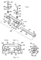
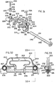
Figure 1 is an exploded front perspective view of a connector constructed in accordance with the principles of the present invention; -
Figure 2 is a front view of the connector shown inFigure 1 ; -
Figure 3A is a cross-section view of the connector taken along the lines 3-3 inFigure 2 in an engaging position; -
Figure 3B is a cross-section view of the connector shown inFigure 3A in a releasing position; -
Figure 4 is a front perspective view of a base of the connector; -
Figure 5 is a front view of the base shown inFigure 4 ; -
Figure 6 is a cross-section view of the base taken along the lines 6-6 inFigure 5 ; -
Figure 7 is a bottom view of the base shown inFigure 4 ; -
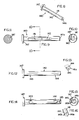
Figure 8 is a front perspective view of a gate of the connector; -
Figure 9 is a bottom view of the gate shown inFigure 8 ; -
Figure 10 is a cross-section view of the gate taken along the lines 10-10 inFigure 9 ; -
Figure 11 is a side view of the gate shown inFigure 8 ; -
Figure 12 is a rear view of the gate shown inFigure 8 ; -
Figure 13 is an auxiliary view of the gate shown inFigure 8 from proximate a middle portion to a distal end of the gate; -
Figure 14 is a top view of the gate shown inFigure 8 ; -
Figure 15 is a side view of the gate shown inFigure 8 ; -
Figure 16 is an auxiliary view of a portion of the gate shown inFigure 8 ; -
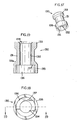
Figure 17 is a front perspective view of an engaging member of the connector; -
Figure 18 is a bottom view of the engaging member shown inFigure 17 ; -
Figure 19 is a cross-section view of the engaging member taken along the lines 19-19 inFigure 18 ; -
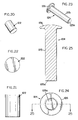
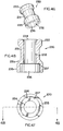
Figure 20 is a front perspective view of a retaining pin of the connector; -
Figure 21 is a front view of the retaining pin shown inFigure 20 ; -
Figure 22 is a bottom view of the retaining pin shown inFigure 20 ; -
Figure 23 is a front perspective view of a rivet of the connector; -
Figure 24 is a bottom view of the rivet shown inFigure 23 ; -
Figure 25 is a cross-section view of the rivet taken along the lines 25-25 inFigure 24 ; -
Figure 26 is a front perspective view of a biasing member of the connector; -
Figure 27 is a bottom view of the biasing member shown inFigure 26 ; -
Figure 28 is a front view of the biasing member shown inFigure 26 ; -
Figure 29 is a front view of the connector shown inFigure 1 operatively connected to a safety harness; -
Figure 30 is a front view of the connector shown inFigure 1 operatively connected to a safety harness and to a self-retracting lifeline; -
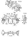
Figure 31 is an exploded front perspective view of another embodiment connector constructed in accordance with the principles of the present invention; -
Figure 32 is a front view of the connector shown inFigure 31 ; -
Figure 33 is a cross-section view of the connector taken along the lines 33-33 inFigure 32 ; -
Figure 34 is a front perspective view of a base of the connector; -
Figure 35 is a front view of the base shown inFigure 34 ; -
Figure 36 is a cross-section view of the base taken along the lines 36-36 inFigure 35 ; -
Figure 37 is a bottom view of the base shown inFigure 34 ; -
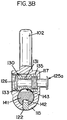
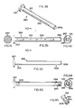
Figure 38 is a front perspective view of a gate of the connector; -
Figure 39 is a bottom view of the gate shown inFigure 38 ; -
Figure 40 is a cross-section view of the gate taken along the lines 40-40 inFigure 39 ; -
Figure 41 is a side view of the gate shown inFigure 38 ; -
Figure 42 is a rear view of the gate shown inFigure 38 ; -
Figure 43 is a top view of the gate shown inFigure 38 ; -
Figure 44 is a side view of the gate shown inFigure 38 ; -
Figure 45 is an auxiliary view of a portion of the gate shown inFigure 38 ; -
Figure 46 is a front perspective view of an engaging member of the connector; -
Figure 47 is a bottom view of the engaging member shown inFigure 46 ; -
Figure 48 is a cross-section view of the engaging member taken along the lines 48-48 inFigure 47 ; -
Figure 49 is a front perspective view of a retaining pin of the connector; -
Figure 50 is a front view of the retaining pin shown inFigure 49 ; -
Figure 51 is a bottom view of the retaining pin shown inFigure 49 ; -
Figure 52 is a bottom perspective view of a rivet of the connector; -
Figure 53 is a bottom view of the rivet shown inFigure 52 ; -
Figure 54 is a rear view of the rivet shown inFigure 52 ; -
Figure 55 is a bottom perspective view of a biasing member of the connector; -
Figure 56 is a bottom view of the biasing member shown inFigure 55 ; and -
Figure 57 is a rear view of the biasing member shown inFigure 55 . - In accordance with common practice, the various described features are not drawn to scale but are drawn to emphasize specific features relevant to the present invention. Reference characters denote like elements throughout the Figures and the text.
- In the following detailed description, reference is made to the accompanying drawings, which form a part hereof, and in which is shown by way of illustration embodiments in which the inventions may be practiced. The following detailed description is, therefore, not to be taken in a limiting sense, and the scope of the present invention is defined only by the claims.
- Embodiments of the present invention provide a connector that is user friendly and secure. For example, the connector could be used to interconnect a safety harness and a self-retracting lifeline.
- For ease of reference, the embodiments are being described in the orientations in which they are shown. Other orientations are possible, and this description should not limit the orientations in which the connectors are used.
- One
embodiment connector 100 is shown inFigures 1-3 and29-30 . Theconnector 100 includes abase 101, receivingportions portions gate 140. Thebase 101 is generally C-shaped and includes an elongate orbar portion 102 with afirst end 103, to which afirst receiving portion 105 and afirst locking portion 107 are operatively connected, and asecond end 104, to which asecond receiving portion 115 and asecond locking portion 117 are operatively connected. The first and second ends 103 and 104 include corners and extension portions that extend downward approximately ninety degrees from thebar portion 102. - The
first receiving portion 105 is generally cylindrical with abore 106 extending parallel to thebar portion 102. One end of the first receivingmember 105 is operatively connected to thefirst end 103 and the remaining portion of the first receivingmember 105 extends inward. Thefirst locking portion 107 is positioned proximate the corner where thefirst end 103 and the first receivingportion 105 are operatively connected. Thefirst locking portion 107 is also generally cylindrical with abore 108, which is perpendicular to thebore 106, and thebores first locking portion 107 includes alarger opening 109 proximate the front and a bottom 110 with a smaller opening 111 proximate the rear as shown inFigures 5 and 6 . - The
second receiving portion 115 is generally cylindrical with abore 116 extending parallel to thebar portion 102. One end of the second receivingmember 115 is operatively connected to thesecond end 104 and the remaining portion of the second receivingmember 115 extends inward. Thesecond locking portion 117 is positioned proximate the corner where thesecond end 104 and thesecond receiving portion 115 are operatively connected. Thesecond locking portion 117 is also generally cylindrical with abore 118, which is perpendicular to thebore 116, and thebores second locking portion 117 includes alarger opening 119 proximate the front and a bottom 120 with asmaller opening 121 proximate the rear as shown inFigures 5 and 6 . Thesecond receiving portion 115 also includes alateral bore 116a on its bottom, which is opposite thesecond locking portion 117. Thelateral bore 116a aligns with the juncture of thebores pin 122. The receivingportions opening 148 therebetween. - Each of the
first locking portion 107 and thesecond locking portion 117 is configured and arranged to receive a biasingmember 138, an engagingmember 130, and arivet 124. These components form a locking mechanism. Therivet 124 includes ahead 126 operatively connected to one end of ashaft 125, which has adistal end 125a opposite thehead 126. The engagingmember 130 includes acylindrical base portion 131 to which a firstflanged portion 133 is operatively connected proximate one end and a secondflanged portion 135 is operatively connected proximate the other end. Abore 132 extends through the engagingmember 130, and anopening 134 in the firstflanged portion 133 and anopening 136 in the secondflanged portion 135 provide access to thebore 132. Theopening 136 in the secondflanged portion 135 is larger than thebore 132 to form aledge portion 137 inside the engagingmember 130 proximate the juncture of thebase portion 131 and the secondflanged portion 135. This is shown inFigures 18 and 19 . The biasingmember 138 is configured and arranged to fit within theopening 136 of the secondflanged portion 135 and one end of the biasingmember 138 contacts theledge portion 137. Along with the engagingmember 130, the biasingmember 138 is also configured and arranged to fit within thebore portion member 138 contacts the bottom 110 or 120. - The
rivet 124 extends through thebore 132 of the engagingmember 130, the bore of the biasingmember 138, and thebore portion distal end 125a is deformed, as shown inFigure 3 , by means well known in the art to secure therivet 124 to the lockingportion rivet 124 captures the engagingmember 130 and the biasingmember 138 within withbore head 126 and the deformeddistal end 125a. The ends of the biasingmember 138 contact theledge portion 137 and the bottom 110 or 120 and place a biasing force on the engagingmember 130 to bias the engagingmember 130 to an engaging position, which is shown inFigure 3A . An opposing force can be placed on thehead 126 of therivet 124 to compress the biasingmember 138 and move the engagingmember 130 from the engaging position to a releasing position, which is shown inFigure 3B . - The
gate 140 includes ahead 147 operatively connected to one end of ashaft 141, which has adistal end 141a opposite thehead 147. The bottom side of theshaft 141 includes aslot 142 that extends along an intermediate portion of theshaft 141. The top side of theshaft 141 includes afirst notch 143 proximate thehead 147 and asecond notch 144 proximate thedistal end 141a. Aramp portion 145 extends from thesecond notch 144 to thedistal end 141a, and thedistal end 141a includes a notchedportion 141b to provide access to theramp portion 145. - Before the retaining
pin 122 is positioned within thelateral bore 116a, at least the locking mechanism proximate thesecond receiving portion 115 is moved into its releasing position and thedistal end 141a of thegate 140 is inserted into thebore 116 until at least theslot 142 of thegate 140 is aligned with thebore 116a. Then the retainingpin 122 is friction fit within thelateral bore 116a and extends into thebore 116 to fit within theslot 142 as show inFigure 3 . The retainingpin 122 acts as a stop member to prevent thegate 140 from sliding all the way out of thesecond receiving portion 115. Because the retainingpin 122 fits within theslot 142, when the retainingpin 122 contacts thegate 140 proximate the end of theslot 142 proximate thedistal end 141a, thegate 140 cannot be slid further out of thesecond receiving portion 115. - When assembled, as shown in
Figures 2 and3 , thegate 140 is positioned within thebores portions pin 122 is positioned within theslot 142, and the secondflanged portions 135 of the engagingmembers 130 are positioned within thenotches gate 140. Thegate 140 includes aslot 142 in which theretaining pin 122 is positioned to not only act as a stop member, as discussed above, but to keep thegate 140 in the desired orientation so that thenotches notches portion member 138, the engagingmember 130, and therivet 124. - In operation, to release the
gate 140, theheads 126 of bothrivets 124 are pressed downward into therespective locking portions members 138 are compressed and the engagingmembers 130 move downward. Each locking mechanism operates independently of the other. Therefore, both locking mechanisms need to be in the releasing position to allow the gate to be opened. As the engagingmembers 130 move downward, the secondflanged portions 135 move out of thenotches cylindrical base portions 131 are positioned proximate thenotches Figure 3B . When thecylindrical base portions 131 are positioned proximate thenotches gate 140 is no longer engaged by the locking mechanisms and there is enough clearance to slide thegate 140 completely out of the first receivingportion 105. Because of the retainingpin 122, thegate 140 cannot be completely slid out of thesecond receiving portion 115. - When the
gate 140 is slid out of the first receivingportion 105, the locking mechanism returns to the engaging position due to the biasing force exerted on the engagingmember 130 by the biasingmember 138. Because thegate 140 remains in thesecond receiving portion 115 and thenotch 144 is not proximate the locking mechanism, the locking mechanism remains in the releasing position. - When the
gate 140 is moved from a closed position to an open position, theopening 148 between the receivingportions Figures 29 and 30 , theconnector 100 may be connected to straps of a safety harness. After the straps have been positioned within theopening 148, thegate 140 is moved from the open position to the closed position to capture the straps between thebar portion 102 and thegate 140. A safety device, such as a self-retracting lifeline, maybe connected to thegate 140 before thegate 140 is slid into the first receivingportion 105 by positioning an aperture of the self-retracting lifeline's connector portion between the receivingportions gate 140 through the connector portion's aperture. To move thegate 140 from the open position into the closed position, thegate 140 is simply slid back into the receivingportions distal end 141a of thegate 140 is slid into the first receivingportion 105, the notchedportion 141b and theramp portion 145 allow the end of thegate 140 proximate thedistal end 141a to be slid past the engagingmember 130. Theramp portion 145 of thegate 140 contacts theangled surface 131a, which interconnects thebase portion 131 and the secondflanged portion 135 of the engagingmember 130, and pushes the engagingmember 130 so that the biasingmember 138 compresses and thebase portion 131 is proximate thenotch 143. When thenotches members 130 by the biasingmembers 138 and thegate 140 cannot be slid outward until both of the locking mechanisms are in the releasing positions. - Another
embodiment connector 200 is shown inFigures 31-33 . Theconnector 200 includes abase 201, receivingportions extension portions portions gate 240. Thebase 201 is generally C-shaped and includes an elongate orbar portion 202 with afirst end 203 and asecond end 204. The first and second ends 203 and 204 include corners and extension portions that extend downward approximately ninety degrees from thebar portion 202. Afirst receiving portion 205, afirst extension portion 250, and afirst locking portion 207 are operatively connected to thefirst end 203, and asecond receiving portion 215, asecond extension portion 255, and asecond locking portion 217 are operatively connected to thesecond end 204. - Two prongs, an outer prong and an inner prong, extend outward from the
first end 203. Operatively connected to the outer prong is the first receivingportion 205, which is generally cylindrical with abore 206 extending parallel to thebar portion 202. Operatively connected to the inner prong is thefirst extension portion 250, which includes aring portion 251 with anaperture 252 in alignment with thebore 206 of the first receivingportion 205. Thefirst locking portion 207 is positioned proximate the juncture of the outer prong and the first receivingportion 205. Thefirst locking portion 207 is also generally cylindrical with abore 208, which is perpendicular to thebore 206, and thebores first locking portion 207 includes alarger opening 209 proximate the front and a bottom 210 with asmaller opening 211 proximate the rear as shown inFigures 35 and 36 . - Two prongs, an outer prong and an inner prong, extend outward from the
second end 204. Operatively connected to the outer prong is thesecond receiving portion 215, which is generally cylindrical with abore 216 extending parallel to thebar portion 202. Operatively connected to the inner prong is thesecond extension portion 255, which includes aring portion 256 with anaperture 257 in alignment with thebore 216 of thesecond receiving portion 215. Thesecond locking portion 217 is positioned proximate the juncture of the outer prong and thesecond receiving portion 215. Thesecond locking portion 217 is also generally cylindrical with abore 218, which is perpendicular to thebore 216, and thebores second locking portion 217 includes alarger opening 219 proximate the front and a bottom 220 with asmaller opening 221 proximate the rear as shown inFigures 35 and 36 . Thesecond receiving portion 215 also includes alateral bore 216a on its bottom, which is opposite thesecond locking portion 217. Thelateral bore 216a aligns with the juncture of thebores pin 222. Theextension portions opening 248a therebetween, the first receivingportion 205 and thefirst extension portion 250 form anopening 248b therebetween, and thesecond receiving portion 215 and thesecond extension portion 255 form anopening 248c therebetween. - Each of the
first locking portion 207 and thesecond locking portion 217 is configured and arranged to receive a biasingmember 238, an engagingmember 230, and arivet 224. These components form a locking mechanism. Therivet 224 includes ahead 226 operatively connected to one end of ashaft 225, which has adistal end 225a opposite thehead 226. The engagingmember 230 includes acylindrical base portion 231 to which a firstflanged portion 233 is operatively connected proximate one end and a secondflanged portion 235 is operatively connected proximate the other end. Abore 232 extends through the engagingmember 230, and anopening 234 in the firstflanged portion 233 and anopening 236 in the secondflanged portion 235 provide access to thebore 232. Theopening 236 in the secondflanged portion 235 is larger than thebore 232 to form aledge portion 237 inside the engagingmember 230 proximate the juncture of thebase portion 231 and the secondflanged portion 235. This is shown inFigures 47 and 48 . The biasingmember 238 is configured and arranged to fit within theopening 236 of the secondflanged portion 235 and one end of the biasingmember 238 contacts theledge portion 237. Along with the engagingmember 230, the biasingmember 238 is also configured and arranged to fit within thebore portion member 238 contacts the bottom 210 or 220. - The
rivet 224 extends through thebore 232 of the engagingmember 230, the bore of the biasingmember 238, and thebore portion distal end 225a is deformed, as shown inFigure 33 , by means well known in the art to secure therivet 224 to the lockingportion rivet 224 captures the engagingmember 230 and the biasingmember 238 within withbore head 226 and the deformeddistal end 225a. The ends of the biasingmember 238 contact theledge portion 237 and the bottom 210 or 220 and place a biasing force on the engagingmember 230 to bias the engagingmember 230 to an engaging position. An opposing force can be placed on thehead 226 of therivet 224 to compress the biasingmember 238 and move the engagingmember 230 from the engaging position to a releasing position. - The
gate 240 includes ahead 247 operatively connected to one end of ashaft 241, which has adistal end 241a opposite thehead 247. The bottom side of theshaft 241 includes aslot 242 that extends along an intermediate portion of theshaft 241. The top side of theshaft 241 includes afirst notch 243 proximate thehead 247 and asecond notch 244 proximate thedistal end 241a. Aramp portion 245 extends from thesecond notch 244 to thedistal end 241a, and thedistal end 241a includes a notched portion 241b to provide access to theramp portion 245. - Before the retaining
pin 222 is positioned within thelateral bore 216a, at least the locking mechanism proximate thesecond receiving portion 215 is moved into its releasing position and thedistal end 241a of thegate 240 is inserted into thebore 216 until at least theslot 242 of thegate 240 is aligned with thebore 216a. Then the retainingpin 222 is friction fit within thelateral bore 216a and extends into thebore 216 to fit within theslot 242 as show inFigure 33 . The retainingpin 222 acts as a stop member to prevent thegate 240 from sliding all the way out of thesecond receiving portion 215. Because the retainingpin 222 fits within theslot 242, when the retainingpin 222 contacts thegate 240 proximate the end of theslot 242 proximate thedistal end 241a, thegate 240 cannot be slid further out of thesecond receiving portion 215. - When assembled, as shown in
Figures 32 and 33 , thegate 240 is positioned within thebores portions apertures second extension portions pin 222 is positioned within theslot 242, and the secondflanged portions 235 of the engagingmembers 230 are positioned within thenotches gate 240. Thegate 240 includes aslot 242 in which theretaining pin 222 is positioned to not only act as a stop member, as discussed above, but to keep thegate 240 in the desired orientation so that thenotches notches portion member 238, the engagingmember 230, and therivet 224. - In operation, to release the
gate 240, theheads 226 of bothrivets 224 are pressed downward into therespective locking portions members 238 are compressed and the engagingmembers 230 move downward. Each locking mechanism operates independently of the other. Therefore, both locking mechanisms need to be in the releasing position to allow the gate to be opened. As the engagingmembers 230 move downward, the secondflanged portions 235 move out of thenotches cylindrical base portions 231 are positioned proximate thenotches cylindrical base portions 231 are positioned proximate thenotches gate 240 is no longer engaged by the locking mechanisms and there is enough clearance to slide thegate 240 completely out of the first receivingportion 205. Because of the retainingpin 222, thegate 240 cannot be completely slid out of thesecond receiving portion 215. - When the
gate 240 is slid out of the first receivingportion 205, the locking mechanism returns to the engaging position due to the biasing force exerted on the engagingmember 230 by the biasingmember 238. Because thegate 240 remains in thesecond receiving portion 215 and thenotch 244 is not proximate the locking mechanism, the locking mechanism remains in the releasing position. - When the
gate 240 is moved from a closed position to an open position, theopenings connector 200 may be connected to straps of a safety harness and a safety device such as a self-retracting lifeline. After the straps have been positioned within theopening 248a, thegate 240 is moved from the open position to the closed position to capture the straps between thebar portion 202 and thegate 240. The safety device, such as a self-retracting lifeline, is connected to thegate 240 before thegate 240 is slid into at least thefirst extension portion 250 and the first receivingportion 205 by positioning an aperture of the self-retracting lifeline's connector portion between theextension portions gate 240 through the connector portion's aperture. If it is desired to connect two safety devices to theconnector 200, a first device is similarly connected between the first receivingportion 205 and thefirst extension portion 250 and a second device is similarly connected between thesecond extension portion 255 and thesecond receiving portion 215. If it is desired to connect three safety devices to theconnector 200, a device is similarly connected to thegate 240 proximate each of theopenings gate 240 from the open position into the closed position, thegate 240 is simply slid through the receivingportion 215, theapertures portion 205. When thedistal end 241a of thegate 240 is slid into the first receivingportion 205, the notched portion 241b and theramp portion 245 allow the end of thegate 240 proximate thedistal end 241a to be slid past the engagingmember 230. Theramp portion 245 of thegate 240 contacts the angled surface 231a, which interconnects thebase portion 231 and the secondflanged portion 235 of the engagingmember 230, and pushes the engagingmember 230 so that the biasingmember 238 compresses and thebase portion 231 is proximate thenotch 243. When thenotches members 230 by the biasingmembers 238 and thegate 240 cannot be slid outward until both of the locking mechanisms are in the releasing positions.
Claims (14)
- A connector, comprising:a base (101) including a first end (103) and a second end (104) forming an opening (148);the first end (103) including a first receiving portion (105), a first locking portion (107), and a first locking mechanism, the first receiving portion (105) including a first receiving portion bore (106), the first locking portion (107) being operatively connected to the first receiving portion and including a first locking portion bore (108) in fluid communication with the first receiving portion bore (106), the first locking mechanism being positioned within the first locking portion bore (108) and having an engaging position and a releasing position, the first locking mechanism having a biasing member (138), an engaging member (130), and a fastener (124), the engaging member (130) including a first flanged portion (133) extending at least partially into the first receiving portion bore (106) in the engaging position, the first flanged portion (133) configured and arranged to move within the first locking portion bore (108) when the first locking mechanism moves between the engaging position and the releasing position; anda gate (140) slidably operatively connected to the second end (104), the gate having a closed position and an open position, the gate (140) spanning the opening and a portion of the gate extending through the first receiving portion bore (106) in the closed position, the gate including a first engaging portion (144) proximate the first receiving portion bore in the closed position, the first flanged portion (133) extending at least partially into the first engaging portion (144) when the gate is in the closed position and the first locking mechanism is in the engaging position to secure the gate (140) to the base (101), the first flanged portion (133) positioned out of the first engaging portion and positioned in the first locking position bore when the first locking mechanism is in the releasing position to allow the gate (140) to be moved relative to the base (101).
- The connector of claim 1, further comprising a slot (142) extending longitudinally along a portion of the gate (140) and a pin (122) operatively connected to the second end (104) of the base (101) extending into the slot (142).
- The connector of claim 1, wherein the first locking mechanism comprises a biasing member (138), an engaging member (130), and a fastener (124), the fastener operatively connecting the biasing member and the engaging member to the first locking portion (107), the biasing member (138) biasing the engaging member (130) in the engaging position, the engaging member (130) including the first flanged portion.
- The connector of claim 1, further comprising a notch (141b) proximate a distal end (141a) of the gate (140) and a ramp portion (145) interconnecting the notch (141b) and the first engaging portion (144), the notch (141b) and the ramp portion (145) assisting in sliding the distal end (141a) of the shaft (141) past the first locking mechanism when the gate (140) is moved from the open position to the closed position.
- The connector of claim 1, further comprising the second end (104) including a second receiving portion (115), a second locking portion (117), and a second locking mechanism, the second receiving portion including a second receiving portion bore (116), the second locking portion (117) being operatively connected to the second receiving portion and including a second locking portion bore (118) in fluid communication with the second receiving portion bore (116), the second locking mechanism being positioned within the second locking portion bore (118) and having an engaging position and a releasing position, the second locking mechanism extending at least partially into the second receiving portion bore in the engaging position, the gate (140) including a second notch (143) proximate the second receiving portion bore (1 16) in the closed position, the second locking mechanism extending at least partially into the second notch (143) when the gate is in the closed position and the second locking mechanism is in the engaging position to secure the gate (140) to the base (101), the second locking mechanism positioned out of the notch (143) when the second locking mechanism is in the releasing position, both of the first and second locking mechanisms are positioned in the releasing positions to allow the gate (140) to be moved relative to the base (101).
- The connector of claim 5, further comprising a first extension portion (250) including a first ring portion (251) with a first aperture (252) and a second extension portion (255) including a second ring portion (256) with a second aperture (257), the first and second apertures (252,257) being aligned with the first and second receiving portion bores (206,216).
- The connector of claim 6, wherein a first opening (248a) is formed by the first extension portion (250) and the second extension portion (255), a second opening (248b) is formed by the first receiving portion (205) and the first extension portion (250), and a third opening (248c) is formed by the second extension portion (255) and the second receiving portion (215).
- The connector of claim 7, wherein a safety harness is operatively connected to the bar portion (202) and a safety device is operatively connected to the gate (240) proximate the first opening (248a).
- The connector of claim 7, wherein a safety harness is operatively connected to the bar portion (202), a first safety device is operatively connected to the gate (240) proximate the second opening (248b), and a second safety device is operatively connected to the gate (240) proximate the third opening (248c).
- The connector of claim 5, wherein the first locking portion bore (108) is perpendicular to the first receiving portion bore (106) and the second locking portion bore (118) is perpendicular to the second receiving portion bore (116).
- The connector of claim 5, wherein the first and second locking mechanisms each comprise a biasing member (138), an engaging member (130), and a fastener (124), the fastener (124) operatively connecting the biasing member (138) and the engaging member (130) to the respective locking portion (107, 117), the biasing member (138) biasing the engaging member (130) in the engaging position.
- The connector of claim 1, wherein the first receiving portion (105) is operatively connected to the base (101).
- The connector of claim 12, wherein the first receiving portion (105) and the base (101) are integral.
- The connector of claim 1, comprising:the base (101) including a bar portion (102), the first receiving portion (105), the first locking portion (107), a the first locking mechanism, a second receiving portion (115), a second locking portion (117), and a second locking mechanism, the first receiving portion (105) being operatively connected to the first end (103) of the bar portion and including a the first receiving portion bore (106), the first locking portion (107) being operatively connected to the first receiving portion (105) and including the first locking portion bore (108) in fluid communication with the first receiving portion bore (106), the first locking mechanism being positioned within the first locking portion bore (108) and extending at least partially into the first receiving portion bore (106), the second receiving portion (115) being operatively connected to a second end (104) of the bar portion and including a second receiving portion bore (116), the second locking portion (117) being operatively connected to the second receiving portion (115) and including a second locking portion bore (118) in fluid communication with the second receiving portion bore (116), the second locking mechanism being positioned within the second locking portion bore (118) and extending at least partially into the second receiving portion bore (116), a first opening (148) being formed by the first receiving portion (105) and the second receiving portion (115), the first receiving portion bore (106) being aligned with the second receiving portion bore (116), the first and second locking mechanisms each having an engaging position and a releasing position;the gate (140) including a head (147) and a shaft (141), the head being operatively connected to one end of the shaft, the shaft including a distal end (141 a) opposite the head, the shaft (141) including the first engaging portion (144) proximate the distal end and a second engaging portion (143) proximate the head (147); andwherein the first and second receiving portion bores (106, 116) are configured and arranged to receive the shaft (141), the first locking mechanism being configured and arranged to engage the first engaging portion (144) in the engaging position and the second locking mechanism being configured and arranged to engage the second engaging portion (143) in the engaging position, and wherein both the first and second locking mechanisms are positioned in the releasing positions to move the gate (140) relative to the base.
Applications Claiming Priority (3)
| Application Number | Priority Date | Filing Date | Title |
|---|---|---|---|
| US201161552551P | 2011-10-28 | 2011-10-28 | |
| US13/660,532 US8938864B2 (en) | 2011-10-28 | 2012-10-25 | Connector |
| PCT/US2012/062107 WO2013063384A2 (en) | 2011-10-28 | 2012-10-26 | Connector |
Publications (2)
| Publication Number | Publication Date |
|---|---|
| EP2771075A2 EP2771075A2 (en) | 2014-09-03 |
| EP2771075B1 true EP2771075B1 (en) | 2020-11-25 |
Family
ID=47178342
Family Applications (1)
| Application Number | Title | Priority Date | Filing Date |
|---|---|---|---|
| EP12784835.6A Active EP2771075B1 (en) | 2011-10-28 | 2012-10-26 | Connector |
Country Status (10)
| Country | Link |
|---|---|
| US (2) | US8938864B2 (en) |
| EP (1) | EP2771075B1 (en) |
| JP (1) | JP5921007B2 (en) |
| CN (1) | CN103874529B (en) |
| AU (1) | AU2012328663B2 (en) |
| BR (1) | BR112014008949B1 (en) |
| CA (1) | CA2846390C (en) |
| MX (1) | MX350949B (en) |
| SG (1) | SG11201401841VA (en) |
| WO (1) | WO2013063384A2 (en) |
Families Citing this family (26)
| Publication number | Priority date | Publication date | Assignee | Title |
|---|---|---|---|---|
| US9273717B2 (en) | 2011-10-27 | 2016-03-01 | D B Industries, Llc | Connector for lifelines |
| US8938864B2 (en) | 2011-10-28 | 2015-01-27 | D B Industries, Llc | Connector |
| US9174073B2 (en) * | 2013-02-08 | 2015-11-03 | D B Industries, Llc | Energy absorber assembly and components thereof |
| CN104030203A (en) * | 2013-03-08 | 2014-09-10 | 煤矿安全设备公司 | Bracket and ascending/descending equipment assembly |
| US9427608B2 (en) * | 2013-05-10 | 2016-08-30 | Honeywell International Inc. | Self-retracting lifeline connecting system |
| FR3013788B1 (en) * | 2013-11-27 | 2016-05-13 | Zedel | IMPROVING WORK SWIVEL ATTACHING DEVICE |
| US9435484B1 (en) * | 2015-05-15 | 2016-09-06 | Aerohook Technology Co., Ltd. | Safety catch connector |
| US10232199B2 (en) * | 2015-06-10 | 2019-03-19 | D B Industries, Llc | Integral safety harness connector assembly |
| FR3049869B1 (en) * | 2016-04-08 | 2018-06-22 | Zedel | HARNESS |
| FR3049870A1 (en) * | 2016-04-08 | 2017-10-13 | Zedel | HARNESS |
| TWM525971U (en) * | 2016-05-06 | 2016-07-21 | Aerohook Technology Co Ltd | Locking type connection device for preventing from falling |
| GB2557308B (en) * | 2016-12-06 | 2020-06-24 | Treemagineers Ltd | Harnesses |
| FR3063652A1 (en) * | 2017-03-13 | 2018-09-14 | Zedel | HARNESS. |
| US10300315B2 (en) * | 2017-06-02 | 2019-05-28 | Akila Tech Co., Ltd. | Partitioned anti-falling connecting device |
| TWI627918B (en) * | 2017-06-16 | 2018-07-01 | 振鋒企業股份有限公司 | Seat belt buckle connecting device |
| US11813487B2 (en) | 2017-07-13 | 2023-11-14 | 3M Innovative Properties Company | Fall arresting device connector |
| US10625105B2 (en) | 2017-09-07 | 2020-04-21 | Msa Technology, Llc | Harness connector |
| US10343001B2 (en) * | 2017-09-07 | 2019-07-09 | Honeywell International Inc. | Fall protection lanyard capable of direct connection to harness webbing |
| BR112020005471A2 (en) * | 2017-09-22 | 2020-09-29 | 3M Innovative Properties Company | parachute device connector |
| FR3072034B1 (en) * | 2017-10-06 | 2019-11-08 | Zedel | HARNESS |
| TWM574499U (en) * | 2018-11-21 | 2019-02-21 | 張恬馨 | Guiding type fall protection back-carrying kit |
| GB2580674B (en) | 2019-01-22 | 2022-12-07 | Checkmate Lifting & Safety Ltd | Coupler for a fall protection device |
| TWI725845B (en) * | 2020-05-14 | 2021-04-21 | 振鋒企業股份有限公司 | Connecting device for seat belt buckle |
| US11524189B2 (en) | 2020-06-08 | 2022-12-13 | Reliance Industries, Llc | Connector |
| CN115869559A (en) * | 2021-09-27 | 2023-03-31 | 霍尼韦尔国际公司 | Safety device connector apparatus for use with a wearable safety harness |
| CA3216232A1 (en) * | 2022-10-07 | 2024-04-07 | Karjen, Incorporated | Retracting pins for securement devices |
Citations (2)
| Publication number | Priority date | Publication date | Assignee | Title |
|---|---|---|---|---|
| US20090269133A1 (en) * | 2008-04-29 | 2009-10-29 | Caterpillar Work Tools B.V. | Locking device for grappling links |
| US8104988B2 (en) * | 2006-05-29 | 2012-01-31 | Bradken Resources Pty Limited | Locking connector system |
Family Cites Families (20)
| Publication number | Priority date | Publication date | Assignee | Title |
|---|---|---|---|---|
| US128087A (en) * | 1872-06-18 | Improvement in plow-clevises | ||
| US923767A (en) * | 1908-08-11 | 1909-06-01 | Nat Malleable Castings Co | Pin and clevis. |
| US3240519A (en) * | 1962-09-26 | 1966-03-15 | Anthony V Weasler | Quickly detachable connection for coupled shaft sections |
| JPS5650179Y2 (en) * | 1977-06-24 | 1981-11-24 | ||
| JPS5723779U (en) * | 1980-07-14 | 1982-02-06 | ||
| JPS606672Y2 (en) * | 1982-06-24 | 1985-03-04 | 近藤鉄工株式会社 | Connecting metal fittings |
| US4645368A (en) * | 1986-01-24 | 1987-02-24 | Dana Corporation | Quick disconnect mechanism for selectively securing a shaft to a power take-off end yoke |
| US5193419A (en) | 1992-06-15 | 1993-03-16 | Lee Chang Chuan | Wrench with telescopic handle |
| US6073724A (en) | 1998-10-23 | 2000-06-13 | D B Industries, Inc. | Connector for a personal safety device |
| JP3394767B1 (en) * | 2001-12-28 | 2003-04-07 | 象印チエンブロック株式会社 | Shackle |
| US7946387B2 (en) | 2006-01-03 | 2011-05-24 | D B Industries, Inc. | Self-retracting lifeline |
| WO2008138058A1 (en) | 2007-05-15 | 2008-11-20 | Worissfield Pty Ltd | A locking device |
| FR2920498B1 (en) * | 2007-08-31 | 2009-11-27 | Zedel | PIVOTING FINGER HAT EQUIPPED WITH A LOCKING RING |
| AU2009219447B2 (en) | 2008-02-25 | 2013-09-12 | Honeywell Safety Products Usa, Inc. | Systems for use with multiple safety devices and connectors for use therewith |
| CN101417164B (en) * | 2008-10-21 | 2011-06-01 | 安徽省电力公司安庆供电公司 | Electric power pole tower cable type anti-drop system |
| US8529778B2 (en) | 2008-11-13 | 2013-09-10 | Molecular Imprints, Inc. | Large area patterning of nano-sized shapes |
| JP5410139B2 (en) | 2009-03-31 | 2014-02-05 | キョーラク株式会社 | Method for manufacturing a luggage box for vehicles |
| FR2944842A1 (en) * | 2009-04-22 | 2010-10-29 | Zedel | CONNECTING LINK WITH LOCKABLE ROTATING RING |
| US9273717B2 (en) | 2011-10-27 | 2016-03-01 | D B Industries, Llc | Connector for lifelines |
| US8938864B2 (en) | 2011-10-28 | 2015-01-27 | D B Industries, Llc | Connector |
-
2012
- 2012-10-25 US US13/660,532 patent/US8938864B2/en active Active
- 2012-10-26 CN CN201280049963.XA patent/CN103874529B/en not_active Expired - Fee Related
- 2012-10-26 AU AU2012328663A patent/AU2012328663B2/en not_active Ceased
- 2012-10-26 SG SG11201401841VA patent/SG11201401841VA/en unknown
- 2012-10-26 MX MX2014005137A patent/MX350949B/en active IP Right Grant
- 2012-10-26 WO PCT/US2012/062107 patent/WO2013063384A2/en active Application Filing
- 2012-10-26 BR BR112014008949-3A patent/BR112014008949B1/en not_active IP Right Cessation
- 2012-10-26 EP EP12784835.6A patent/EP2771075B1/en active Active
- 2012-10-26 CA CA2846390A patent/CA2846390C/en active Active
- 2012-10-26 JP JP2014539039A patent/JP5921007B2/en active Active
-
2014
- 2014-12-30 US US14/585,593 patent/US9585439B2/en active Active
Patent Citations (2)
| Publication number | Priority date | Publication date | Assignee | Title |
|---|---|---|---|---|
| US8104988B2 (en) * | 2006-05-29 | 2012-01-31 | Bradken Resources Pty Limited | Locking connector system |
| US20090269133A1 (en) * | 2008-04-29 | 2009-10-29 | Caterpillar Work Tools B.V. | Locking device for grappling links |
Also Published As
| Publication number | Publication date |
|---|---|
| US9585439B2 (en) | 2017-03-07 |
| MX2014005137A (en) | 2014-08-27 |
| CN103874529A (en) | 2014-06-18 |
| JP2014535027A (en) | 2014-12-25 |
| BR112014008949B1 (en) | 2021-04-20 |
| CA2846390A1 (en) | 2013-05-02 |
| CA2846390C (en) | 2020-03-24 |
| SG11201401841VA (en) | 2014-05-29 |
| WO2013063384A2 (en) | 2013-05-02 |
| US8938864B2 (en) | 2015-01-27 |
| US20130104351A1 (en) | 2013-05-02 |
| AU2012328663A1 (en) | 2014-03-13 |
| EP2771075A2 (en) | 2014-09-03 |
| WO2013063384A3 (en) | 2013-09-19 |
| BR112014008949A2 (en) | 2017-05-02 |
| MX350949B (en) | 2017-09-26 |
| JP5921007B2 (en) | 2016-05-24 |
| AU2012328663B2 (en) | 2016-09-29 |
| US20150107059A1 (en) | 2015-04-23 |
| CN103874529B (en) | 2016-08-24 |
Similar Documents
| Publication | Publication Date | Title |
|---|---|---|
| EP2771075B1 (en) | Connector | |
| CN107110194B (en) | Clasp | |
| EP1660192B1 (en) | Dorsal pad assembly for use with a safety harness | |
| US10258814B2 (en) | Breakaway keeper | |
| AU2010232957B2 (en) | Buckle | |
| US9174073B2 (en) | Energy absorber assembly and components thereof | |
| US7114225B2 (en) | Connector | |
| EP3074093A1 (en) | Rope grab | |
| US20230000214A1 (en) | Automatic snap buckle | |
| CN212325644U (en) | Fastener device | |
| CA2480613C (en) | Connector | |
| KR20070021104A (en) | Dorsal pad assembly for use with a safety harness |
Legal Events
| Date | Code | Title | Description |
|---|---|---|---|
| PUAI | Public reference made under article 153(3) epc to a published international application that has entered the european phase |
Free format text: ORIGINAL CODE: 0009012 |
|
| 17P | Request for examination filed |
Effective date: 20140515 |
|
| AK | Designated contracting states |
Kind code of ref document: A2 Designated state(s): AL AT BE BG CH CY CZ DE DK EE ES FI FR GB GR HR HU IE IS IT LI LT LU LV MC MK MT NL NO PL PT RO RS SE SI SK SM TR |
|
| DAX | Request for extension of the european patent (deleted) | ||
| STAA | Information on the status of an ep patent application or granted ep patent |
Free format text: STATUS: EXAMINATION IS IN PROGRESS |
|
| 17Q | First examination report despatched |
Effective date: 20190503 |
|
| GRAP | Despatch of communication of intention to grant a patent |
Free format text: ORIGINAL CODE: EPIDOSNIGR1 |
|
| STAA | Information on the status of an ep patent application or granted ep patent |
Free format text: STATUS: GRANT OF PATENT IS INTENDED |
|
| INTG | Intention to grant announced |
Effective date: 20200603 |
|
| GRAS | Grant fee paid |
Free format text: ORIGINAL CODE: EPIDOSNIGR3 |
|
| GRAA | (expected) grant |
Free format text: ORIGINAL CODE: 0009210 |
|
| STAA | Information on the status of an ep patent application or granted ep patent |
Free format text: STATUS: THE PATENT HAS BEEN GRANTED |
|
| AK | Designated contracting states |
Kind code of ref document: B1 Designated state(s): AL AT BE BG CH CY CZ DE DK EE ES FI FR GB GR HR HU IE IS IT LI LT LU LV MC MK MT NL NO PL PT RO RS SE SI SK SM TR |
|
| REG | Reference to a national code |
Ref country code: GB Ref legal event code: FG4D |
|
| REG | Reference to a national code |
Ref country code: CH Ref legal event code: EP |
|
| REG | Reference to a national code |
Ref country code: DE Ref legal event code: R096 Ref document number: 602012073408 Country of ref document: DE |
|
| REG | Reference to a national code |
Ref country code: AT Ref legal event code: REF Ref document number: 1337625 Country of ref document: AT Kind code of ref document: T Effective date: 20201215 |
|
| REG | Reference to a national code |
Ref country code: IE Ref legal event code: FG4D |
|
| REG | Reference to a national code |
Ref country code: AT Ref legal event code: MK05 Ref document number: 1337625 Country of ref document: AT Kind code of ref document: T Effective date: 20201125 |
|
| REG | Reference to a national code |
Ref country code: NL Ref legal event code: MP Effective date: 20201125 |
|
| PG25 | Lapsed in a contracting state [announced via postgrant information from national office to epo] |
Ref country code: GR Free format text: LAPSE BECAUSE OF FAILURE TO SUBMIT A TRANSLATION OF THE DESCRIPTION OR TO PAY THE FEE WITHIN THE PRESCRIBED TIME-LIMIT Effective date: 20210226 Ref country code: RS Free format text: LAPSE BECAUSE OF FAILURE TO SUBMIT A TRANSLATION OF THE DESCRIPTION OR TO PAY THE FEE WITHIN THE PRESCRIBED TIME-LIMIT Effective date: 20201125 Ref country code: FI Free format text: LAPSE BECAUSE OF FAILURE TO SUBMIT A TRANSLATION OF THE DESCRIPTION OR TO PAY THE FEE WITHIN THE PRESCRIBED TIME-LIMIT Effective date: 20201125 Ref country code: PT Free format text: LAPSE BECAUSE OF FAILURE TO SUBMIT A TRANSLATION OF THE DESCRIPTION OR TO PAY THE FEE WITHIN THE PRESCRIBED TIME-LIMIT Effective date: 20210325 Ref country code: NO Free format text: LAPSE BECAUSE OF FAILURE TO SUBMIT A TRANSLATION OF THE DESCRIPTION OR TO PAY THE FEE WITHIN THE PRESCRIBED TIME-LIMIT Effective date: 20210225 |
|
| PG25 | Lapsed in a contracting state [announced via postgrant information from national office to epo] |
Ref country code: SE Free format text: LAPSE BECAUSE OF FAILURE TO SUBMIT A TRANSLATION OF THE DESCRIPTION OR TO PAY THE FEE WITHIN THE PRESCRIBED TIME-LIMIT Effective date: 20201125 Ref country code: IS Free format text: LAPSE BECAUSE OF FAILURE TO SUBMIT A TRANSLATION OF THE DESCRIPTION OR TO PAY THE FEE WITHIN THE PRESCRIBED TIME-LIMIT Effective date: 20210325 Ref country code: PL Free format text: LAPSE BECAUSE OF FAILURE TO SUBMIT A TRANSLATION OF THE DESCRIPTION OR TO PAY THE FEE WITHIN THE PRESCRIBED TIME-LIMIT Effective date: 20201125 Ref country code: LV Free format text: LAPSE BECAUSE OF FAILURE TO SUBMIT A TRANSLATION OF THE DESCRIPTION OR TO PAY THE FEE WITHIN THE PRESCRIBED TIME-LIMIT Effective date: 20201125 Ref country code: BG Free format text: LAPSE BECAUSE OF FAILURE TO SUBMIT A TRANSLATION OF THE DESCRIPTION OR TO PAY THE FEE WITHIN THE PRESCRIBED TIME-LIMIT Effective date: 20210225 Ref country code: AT Free format text: LAPSE BECAUSE OF FAILURE TO SUBMIT A TRANSLATION OF THE DESCRIPTION OR TO PAY THE FEE WITHIN THE PRESCRIBED TIME-LIMIT Effective date: 20201125 |
|
| REG | Reference to a national code |
Ref country code: LT Ref legal event code: MG9D |
|
| PG25 | Lapsed in a contracting state [announced via postgrant information from national office to epo] |
Ref country code: HR Free format text: LAPSE BECAUSE OF FAILURE TO SUBMIT A TRANSLATION OF THE DESCRIPTION OR TO PAY THE FEE WITHIN THE PRESCRIBED TIME-LIMIT Effective date: 20201125 |
|
| PG25 | Lapsed in a contracting state [announced via postgrant information from national office to epo] |
Ref country code: SM Free format text: LAPSE BECAUSE OF FAILURE TO SUBMIT A TRANSLATION OF THE DESCRIPTION OR TO PAY THE FEE WITHIN THE PRESCRIBED TIME-LIMIT Effective date: 20201125 Ref country code: EE Free format text: LAPSE BECAUSE OF FAILURE TO SUBMIT A TRANSLATION OF THE DESCRIPTION OR TO PAY THE FEE WITHIN THE PRESCRIBED TIME-LIMIT Effective date: 20201125 Ref country code: CZ Free format text: LAPSE BECAUSE OF FAILURE TO SUBMIT A TRANSLATION OF THE DESCRIPTION OR TO PAY THE FEE WITHIN THE PRESCRIBED TIME-LIMIT Effective date: 20201125 Ref country code: RO Free format text: LAPSE BECAUSE OF FAILURE TO SUBMIT A TRANSLATION OF THE DESCRIPTION OR TO PAY THE FEE WITHIN THE PRESCRIBED TIME-LIMIT Effective date: 20201125 Ref country code: SK Free format text: LAPSE BECAUSE OF FAILURE TO SUBMIT A TRANSLATION OF THE DESCRIPTION OR TO PAY THE FEE WITHIN THE PRESCRIBED TIME-LIMIT Effective date: 20201125 Ref country code: LT Free format text: LAPSE BECAUSE OF FAILURE TO SUBMIT A TRANSLATION OF THE DESCRIPTION OR TO PAY THE FEE WITHIN THE PRESCRIBED TIME-LIMIT Effective date: 20201125 |
|
| REG | Reference to a national code |
Ref country code: DE Ref legal event code: R097 Ref document number: 602012073408 Country of ref document: DE |
|
| PG25 | Lapsed in a contracting state [announced via postgrant information from national office to epo] |
Ref country code: DK Free format text: LAPSE BECAUSE OF FAILURE TO SUBMIT A TRANSLATION OF THE DESCRIPTION OR TO PAY THE FEE WITHIN THE PRESCRIBED TIME-LIMIT Effective date: 20201125 |
|
| PLBE | No opposition filed within time limit |
Free format text: ORIGINAL CODE: 0009261 |
|
| STAA | Information on the status of an ep patent application or granted ep patent |
Free format text: STATUS: NO OPPOSITION FILED WITHIN TIME LIMIT |
|
| PG25 | Lapsed in a contracting state [announced via postgrant information from national office to epo] |
Ref country code: IT Free format text: LAPSE BECAUSE OF FAILURE TO SUBMIT A TRANSLATION OF THE DESCRIPTION OR TO PAY THE FEE WITHIN THE PRESCRIBED TIME-LIMIT Effective date: 20201125 Ref country code: AL Free format text: LAPSE BECAUSE OF FAILURE TO SUBMIT A TRANSLATION OF THE DESCRIPTION OR TO PAY THE FEE WITHIN THE PRESCRIBED TIME-LIMIT Effective date: 20201125 Ref country code: NL Free format text: LAPSE BECAUSE OF FAILURE TO SUBMIT A TRANSLATION OF THE DESCRIPTION OR TO PAY THE FEE WITHIN THE PRESCRIBED TIME-LIMIT Effective date: 20201125 |
|
| 26N | No opposition filed |
Effective date: 20210826 |
|
| PG25 | Lapsed in a contracting state [announced via postgrant information from national office to epo] |
Ref country code: ES Free format text: LAPSE BECAUSE OF FAILURE TO SUBMIT A TRANSLATION OF THE DESCRIPTION OR TO PAY THE FEE WITHIN THE PRESCRIBED TIME-LIMIT Effective date: 20201125 Ref country code: SI Free format text: LAPSE BECAUSE OF FAILURE TO SUBMIT A TRANSLATION OF THE DESCRIPTION OR TO PAY THE FEE WITHIN THE PRESCRIBED TIME-LIMIT Effective date: 20201125 |
|
| REG | Reference to a national code |
Ref country code: CH Ref legal event code: PL |
|
| PG25 | Lapsed in a contracting state [announced via postgrant information from national office to epo] |
Ref country code: IS Free format text: LAPSE BECAUSE OF FAILURE TO SUBMIT A TRANSLATION OF THE DESCRIPTION OR TO PAY THE FEE WITHIN THE PRESCRIBED TIME-LIMIT Effective date: 20210325 |
|
| REG | Reference to a national code |
Ref country code: BE Ref legal event code: MM Effective date: 20211031 |
|
| GBPC | Gb: european patent ceased through non-payment of renewal fee |
Effective date: 20211026 |
|
| PG25 | Lapsed in a contracting state [announced via postgrant information from national office to epo] |
Ref country code: MC Free format text: LAPSE BECAUSE OF FAILURE TO SUBMIT A TRANSLATION OF THE DESCRIPTION OR TO PAY THE FEE WITHIN THE PRESCRIBED TIME-LIMIT Effective date: 20201125 |
|
| PG25 | Lapsed in a contracting state [announced via postgrant information from national office to epo] |
Ref country code: LU Free format text: LAPSE BECAUSE OF NON-PAYMENT OF DUE FEES Effective date: 20211026 Ref country code: GB Free format text: LAPSE BECAUSE OF NON-PAYMENT OF DUE FEES Effective date: 20211026 Ref country code: BE Free format text: LAPSE BECAUSE OF NON-PAYMENT OF DUE FEES Effective date: 20211031 |
|
| PG25 | Lapsed in a contracting state [announced via postgrant information from national office to epo] |
Ref country code: LI Free format text: LAPSE BECAUSE OF NON-PAYMENT OF DUE FEES Effective date: 20211031 Ref country code: CH Free format text: LAPSE BECAUSE OF NON-PAYMENT OF DUE FEES Effective date: 20211031 |
|
| PG25 | Lapsed in a contracting state [announced via postgrant information from national office to epo] |
Ref country code: FR Free format text: LAPSE BECAUSE OF NON-PAYMENT OF DUE FEES Effective date: 20211031 |
|
| PG25 | Lapsed in a contracting state [announced via postgrant information from national office to epo] |
Ref country code: IE Free format text: LAPSE BECAUSE OF NON-PAYMENT OF DUE FEES Effective date: 20211026 |
|
| PG25 | Lapsed in a contracting state [announced via postgrant information from national office to epo] |
Ref country code: HU Free format text: LAPSE BECAUSE OF FAILURE TO SUBMIT A TRANSLATION OF THE DESCRIPTION OR TO PAY THE FEE WITHIN THE PRESCRIBED TIME-LIMIT; INVALID AB INITIO Effective date: 20121026 Ref country code: CY Free format text: LAPSE BECAUSE OF FAILURE TO SUBMIT A TRANSLATION OF THE DESCRIPTION OR TO PAY THE FEE WITHIN THE PRESCRIBED TIME-LIMIT Effective date: 20201125 |
|
| P01 | Opt-out of the competence of the unified patent court (upc) registered |
Effective date: 20230530 |
|
| PGFP | Annual fee paid to national office [announced via postgrant information from national office to epo] |
Ref country code: DE Payment date: 20230920 Year of fee payment: 12 |