EP3204094B1 - Ensemble conduit de fluide ayant un filtre de capture de gaz dans le trajet d'écoulement de fluide - Google Patents
Ensemble conduit de fluide ayant un filtre de capture de gaz dans le trajet d'écoulement de fluide Download PDFInfo
- Publication number
- EP3204094B1 EP3204094B1 EP15734028.2A EP15734028A EP3204094B1 EP 3204094 B1 EP3204094 B1 EP 3204094B1 EP 15734028 A EP15734028 A EP 15734028A EP 3204094 B1 EP3204094 B1 EP 3204094B1
- Authority
- EP
- European Patent Office
- Prior art keywords
- fluid
- gas trapping
- cap
- trapping filter
- reservoir
- Prior art date
- Legal status (The legal status is an assumption and is not a legal conclusion. Google has not performed a legal analysis and makes no representation as to the accuracy of the status listed.)
- Active
Links
Images


Classifications
-
- A—HUMAN NECESSITIES
- A61—MEDICAL OR VETERINARY SCIENCE; HYGIENE
- A61M—DEVICES FOR INTRODUCING MEDIA INTO, OR ONTO, THE BODY; DEVICES FOR TRANSDUCING BODY MEDIA OR FOR TAKING MEDIA FROM THE BODY; DEVICES FOR PRODUCING OR ENDING SLEEP OR STUPOR
- A61M5/00—Devices for bringing media into the body in a subcutaneous, intra-vascular or intramuscular way; Accessories therefor, e.g. filling or cleaning devices, arm-rests
- A61M5/36—Devices for bringing media into the body in a subcutaneous, intra-vascular or intramuscular way; Accessories therefor, e.g. filling or cleaning devices, arm-rests with means for eliminating or preventing injection or infusion of air into body
- A61M5/38—Devices for bringing media into the body in a subcutaneous, intra-vascular or intramuscular way; Accessories therefor, e.g. filling or cleaning devices, arm-rests with means for eliminating or preventing injection or infusion of air into body using hydrophilic or hydrophobic filters
-
- A—HUMAN NECESSITIES
- A61—MEDICAL OR VETERINARY SCIENCE; HYGIENE
- A61M—DEVICES FOR INTRODUCING MEDIA INTO, OR ONTO, THE BODY; DEVICES FOR TRANSDUCING BODY MEDIA OR FOR TAKING MEDIA FROM THE BODY; DEVICES FOR PRODUCING OR ENDING SLEEP OR STUPOR
- A61M39/00—Tubes, tube connectors, tube couplings, valves, access sites or the like, specially adapted for medical use
- A61M39/10—Tube connectors; Tube couplings
-
- A—HUMAN NECESSITIES
- A61—MEDICAL OR VETERINARY SCIENCE; HYGIENE
- A61M—DEVICES FOR INTRODUCING MEDIA INTO, OR ONTO, THE BODY; DEVICES FOR TRANSDUCING BODY MEDIA OR FOR TAKING MEDIA FROM THE BODY; DEVICES FOR PRODUCING OR ENDING SLEEP OR STUPOR
- A61M5/00—Devices for bringing media into the body in a subcutaneous, intra-vascular or intramuscular way; Accessories therefor, e.g. filling or cleaning devices, arm-rests
- A61M5/14—Infusion devices, e.g. infusing by gravity; Blood infusion; Accessories therefor
- A61M5/142—Pressure infusion, e.g. using pumps
- A61M5/14244—Pressure infusion, e.g. using pumps adapted to be carried by the patient, e.g. portable on the body
-
- A—HUMAN NECESSITIES
- A61—MEDICAL OR VETERINARY SCIENCE; HYGIENE
- A61M—DEVICES FOR INTRODUCING MEDIA INTO, OR ONTO, THE BODY; DEVICES FOR TRANSDUCING BODY MEDIA OR FOR TAKING MEDIA FROM THE BODY; DEVICES FOR PRODUCING OR ENDING SLEEP OR STUPOR
- A61M5/00—Devices for bringing media into the body in a subcutaneous, intra-vascular or intramuscular way; Accessories therefor, e.g. filling or cleaning devices, arm-rests
- A61M5/14—Infusion devices, e.g. infusing by gravity; Blood infusion; Accessories therefor
- A61M5/162—Needle sets, i.e. connections by puncture between reservoir and tube ; Connections between reservoir and tube
-
- A—HUMAN NECESSITIES
- A61—MEDICAL OR VETERINARY SCIENCE; HYGIENE
- A61M—DEVICES FOR INTRODUCING MEDIA INTO, OR ONTO, THE BODY; DEVICES FOR TRANSDUCING BODY MEDIA OR FOR TAKING MEDIA FROM THE BODY; DEVICES FOR PRODUCING OR ENDING SLEEP OR STUPOR
- A61M2205/00—General characteristics of the apparatus
- A61M2205/75—General characteristics of the apparatus with filters
- A61M2205/7527—General characteristics of the apparatus with filters liquophilic, hydrophilic
-
- A—HUMAN NECESSITIES
- A61—MEDICAL OR VETERINARY SCIENCE; HYGIENE
- A61M—DEVICES FOR INTRODUCING MEDIA INTO, OR ONTO, THE BODY; DEVICES FOR TRANSDUCING BODY MEDIA OR FOR TAKING MEDIA FROM THE BODY; DEVICES FOR PRODUCING OR ENDING SLEEP OR STUPOR
- A61M5/00—Devices for bringing media into the body in a subcutaneous, intra-vascular or intramuscular way; Accessories therefor, e.g. filling or cleaning devices, arm-rests
- A61M5/14—Infusion devices, e.g. infusing by gravity; Blood infusion; Accessories therefor
- A61M5/165—Filtering accessories, e.g. blood filters, filters for infusion liquids
Definitions
- Embodiments of the subject matter described herein relate generally to fluid infusion devices for delivering a medication fluid to the body of a user. More particularly, embodiments of the subject matter relate to the use of a gas trapping filter in the medication fluid flow path.
- Certain diseases or conditions may be treated, according to modern medical techniques, by delivering a medication fluid or other substance to the body of a patient, either in a continuous manner or at particular times or time intervals within an overall time period.
- diabetes is commonly treated by delivering defined amounts of insulin to the patient at appropriate times.
- Some common modes of providing insulin therapy to a patient include delivery of insulin through manually operated syringes and insulin pens.
- Other modern systems employ programmable fluid infusion devices (e.g., continuous insulin infusion devices such as insulin pumps) to deliver controlled amounts of insulin or other drugs to a patient.
- a fluid infusion device suitable for use as an insulin pump may be realized as an external device or an implantable device, which is surgically implanted into the body of the patient.
- External fluid infusion devices include devices designed for use in a generally stationary location (for example, in a hospital or clinic), and devices configured for ambulatory or portable use (to be carried by a patient).
- External fluid infusion devices may establish a fluid flow path from a fluid reservoir to the patient via, for example, a suitable hollow tubing.
- the hollow tubing may be connected to a hollow fluid delivery needle that is designed to pierce the patient's skin to deliver an infusion fluid to the body.
- the hollow tubing may be connected directly to the patient's body through a cannula or set of micro-needles.
- EP 2 229 970 shows a bubble trap consisting of an upstream antechamber (containment chamber) and multiple fluid outlets, referred to as a "grate" leading to a downstream chamber.
- a bubble in the fluid line is unable to pass through the narrow passages and, therefore, remains in the antechamber.
- US 3,631,654 shows an arrangement for venting gas from a liquid feed line and consisting of a filter consisting of two parts.
- a first part is in the liquid flow path and comprises a hydrophilic material (wetted by and passes the liquid, column 1, line 5).
- the second part of the filter is between the liquid flow path and the outside air and comprises a liquid repellent filter. This is capable of passing gas to the outside air, but not passing liquid.
- US 2005/0161042 shows an arrangement for removing liquid from a gas stream being fed to a gas analyzer. It also captures particulates in the gas stream.
- the device has gas stream path with a liner consisting of a filter material, which is able to absorb liquid and thereby extract it from the gas stream.
- This document also discloses structures for holding in-stream filters for the purpose of extracting moisture from the gas. The function of hydrophilic and hydrophobic filters is mentioned in this context.
- US 2002/077598 shows a pump with a replaceable insulin reservoir comprising a syringe body and piston.
- the reservoir has a cap which attaches to infusion tubing and can be removed and replaced manually by twisting and turning an upstanding blade-like grip on the upper surface of the cap.
- a screw connection between the syringe piston and the pump mechanism is kept sterile by a sterilizing agent admitted via a porous member.
- CN 103100131 shows a bubble trap for a fluid line consisting of a chamber having two halves separated by a liquid permeable, gas impermeable membrane.
- the upstream half also comprises gas vents covered with a gas permeable, liquid impermeable membrane. Bubble contained within the fluid flow are unable to pass the gas impermeable membrane and are vented from the gas permeable membrane.
- US 3978857 presents a device for filtering particulates of 5 micron size and larger from a parenteral solution prior to infusion into a patient.
- An exemplary embodiment of the fluid conduit assembly includes a structure defining a flow path for the medication fluid and a gas trapping filter coupled to the structure.
- the gas trapping filter is positioned in the flow path to filter particulates from the medication fluid and retain gas bubbles from the medication fluid.
- a fluid delivery system is also disclosed herein.
- An exemplary embodiment of the system includes: a fluid infusion pump to provide a medication fluid; a fluid conduit assembly coupled to the fluid infusion pump; and a gas trapping filter.
- the fluid conduit delivers the medication fluid to a user, and the fluid conduit assembly defines a flow path for the medication fluid.
- the gas trapping filter is positioned in the flow path to filter particulates from the medication fluid and retain gas bubbles from the medication fluid.
- An exemplary embodiment of the fluid conduit assembly includes a body section to receive a fluid reservoir, and a flow path defined in the body section.
- the flow path carries fluid from the fluid reservoir when the body section is coupled to the fluid reservoir.
- the fluid conduit assembly also has a length of tubing extending from the body section and in fluid communication with the flow path. The length of tubing carries fluid from the body section during a fluid delivery operation.
- the fluid conduit assembly also has a partially or predominantly hydrophilic gas trapping filter positioned in the flow path to filter particulates from the medication fluid and retain gas bubbles from the medication fluid.
- One embodiment of the present invention comprises a cap for a reservoir of a medicinal fluid which provides a fluid flow path for the medicinal fluid to tubing used to deliver said fluid to a user; said cap comprising: a lower body section configured to be able to engage with the reservoir and having an axial bore to conduct the medicinal fluid from the reservoir; an upper body section having an axial bore for connection at one end to the tubing, the axial bore of the upper body section being in fluid communication with the axial bore of the lower body section to receive the medication fluid via an internal chamber; wherein a gas trapping filter is housed within the internal chamber and configured to retain gas bubbles thereby preventing said gas from leaving the internal chamber.
- the gas trapping filter may be adapted to have one or more of the following additional functions: a. filter out particulates; b. adsorb or absorb silicone oil; c. form a depot of a drug such that the drug is released into the medicinal fluid as it passes through.
- the gas trapping filter is adapted to filter out particulates, it can have a pore size within the range of 0.45 to 5.00 microns.
- the gas trapping filter may comprise a hydrophilic sponge, felt or fiber composite material. If the gas trapping filter is of felt it preferably has a pore size in the range 1-100 micrometres, more preferably 20 to 40 micrometres. If the gas trapping filter is of sponge it preferably has a pore size in the range 20 micrometres to 1 millimetre.
- the lower body section and the upper body section may be integral with one another. Whether or not the body sections are integral the lower body section may include an upstream hollow needle disposed axially within the axial bore and in fluid communication with the internal chamber upstream of the gas trapping filter for piecing a septum in the reservoir and conducting the medicinal fluid therefrom to the internal chamber.
- the gas trapping filter may comprise a discrete or an integrally formed cylindrical component axially disposed in the internal chamber and having a ratio of diameter to height of greater than unity, preferably 5:1 or greater.
- the gas trapping filter may be is held in the internal chamber by a first annular flange forming part of the lower body section, and second annular flange forming part of the upper body section, at least one of said annular flanges also sealing against margins of respective major surfaces of the gas trapping filter ensuring that the flow of medication fluid is through a central region of the filter.
- the gas trapping filter may comprise a discrete cylindrical component axially disposed in the internal chamber and having a ratio of diameter to height of less than or equal to unity.
- a hydrophilic membrane separating the internal chamber from the bore of the upper body section.
- the upper body section may be a manual grip radially outwardly from the gas trapping filter enabling the cap to readily be turned by hand about its longitudinal axis.
- Such a cap can form part of a disposible fluid delivery assembly comprising a reservoir of the medicinal fluid, wherein the cap is further being provided with thread or bayonet fitting for detachably mounting the reservoir in an infusion pump, whereby the assembly can be detached for disposal by turning the cap via said manual grip.
- the invention provides a fluid delivery system for delivering a medicinal fluid to a user comprising: an infusion pump including a reservoir of the medicinal fluid, said reservoir having a cap as described above; a length of tubing connected at a proximal end to the axial bore of the upper body section of the cap, and at a distal end to an infusion unit having a canula to enable fluid from the reservoir to be infused into the body of the user during operation of the pump.
- the present invention according to a further embodiment provides a fluid connector assembly for a medication fluid comprising: a first connector having a bore for connection at one end to an upstream tubing; a second connector having a bore for connection at one end to a downstream tubing; the first and second connectors being detachably couplable, such that when coupled the respective bores are in fluid communication allowing flow of the medication fluid from the upstream tubing to the downstream tubing via the said coupled bores; wherein one of the first and second connectors contains a hollow needle and the other contains a septum, and when the first and second connectors are coupled the needle pierces the septum thereby providing the said fluid communication between the bores of the said respective connectors; a gas trapping filter disposed in the bore of the second connector to retain gas bubbles and hinder such bubbles from traveling with the medication fluid into the downstream tubing.
- the gas trapping filter is adapted to have one or more of the following additional functions: a. filter out particulates; b. adsorb or absorb silicone oil; c. form a depot of a drug such that the drug is released into the medicinal fluid as it passes through.
- the gas trapping filter may is mold inside the bore of the second connector forming an integral component therewith.
- the fluid connector assembly may further include a second gas trapping filter disposed in the bore of the first connector to detain gas bubbles in the medication fluid entering the fluid connector assembly from the upstream tubing.
- the second gas trapping filter may be adapted to have one or more of the following additional functions: a. filter out particulates; b. adsorb or absorb silicone oil; c. form a depot of a drug such that the drug is released into the medicinal fluid as it passes through.
- the gas trapping filter may be of a predominantly hydrophilic material optionally exhibiting up to 50% hydrophobicity.
- the subject matter described here relates to certain assemblies, components, and features of a fluid infusion system of the type used to treat a medical condition of a patient.
- the fluid infusion system is used for infusing a medication fluid into the body of a user.
- the non-limiting examples described below relate to a medical device used to treat diabetes (more specifically, an insulin pump), although embodiments of the disclosed subject matter are not so limited.
- the medication fluid is insulin in certain embodiments.
- many other fluids may be administered through infusion such as, but not limited to, disease treatments, drugs to treat pulmonary hypertension, iron chelation drugs, pain medications, anti-cancer treatments, medications, vitamins, hormones, or the like.
- the gas trapping filter described below could be utilized in the context of other fluid delivery systems if so desired.
- infusion pumps and/or related pump drive systems used to administer insulin and other medications may be of the type described in, but not limited to, United States patent numbers: 4,562,751 ; 4,678,408 ; 4,685,903 ; 5,080,653 ; 5,505,709 ; 5,097,122 ; 6,485,465 ; 6,554,798 ; 6,558,351 ; 6,659,980 ; 6,752,787 ; 6,817,990 ; 6,932,584 ; and 7,621,893
- FIG. 1 is a simplified block diagram representation of an embodiment of a fluid delivery system 100, which can be utilized to administer a medication fluid such as insulin to a patient.
- the fluid delivery system 100 includes a fluid infusion device 102 (e.g., an infusion pump) and a fluid conduit assembly 104 that is coupled to, integrated with, or otherwise associated with the fluid infusion device 102.
- the fluid infusion device 102 includes a fluid reservoir 106 or an equivalent supply of the medication fluid to be administered.
- the fluid infusion device 102 is operated in a controlled manner to deliver the medication fluid to the user via the fluid conduit assembly 104.
- the fluid delivery system 100 also includes a gas trapping filter that is positioned in the fluid flow path. In certain embodiments, the gas trapping filter is located within the fluid flow path defined by the fluid conduit assembly 104.
- the fluid infusion device 102 may be provided in any desired configuration or platform.
- the fluid infusion device is realized as a portable unit that can be carried or worn by the patient.
- FIG. 2 is a plan view of an exemplary embodiment of a fluid delivery system 200 that includes a portable fluid infusion device 202 and a fluid conduit assembly that takes the form of an infusion set component 204.
- the infusion set component 204 can be coupled to the fluid infusion device 202 as depicted in FIG. 2 .
- the fluid infusion device 202 accommodates a fluid reservoir (hidden from view in FIG. 2 ) for the medication fluid to be delivered to the user.
- the illustrated embodiment of the infusion set component 204 includes, without limitation: a tube 210; an infusion unit 212 coupled to the distal end of the tube 210; and a connector assembly 214 coupled to the proximal end of the tube 210.
- the fluid infusion device 202 is designed to be carried or worn by the patient, and the infusion set component 204 terminates at the infusion unit 212 such that the fluid infusion device 202 can deliver fluid to the body of the patient via the tube 210.
- the fluid infusion device 202 may leverage a number of conventional features, components, elements, and characteristics of existing fluid infusion devices.
- the fluid infusion device 202 may incorporate some of the features, components, elements, and/or characteristics described in United States Patent numbers 6,485,465 and 7,621,893 .
- the infusion set component 204 defines a fluid flow path that fluidly couples the fluid reservoir to the infusion unit 212.
- the connector assembly 214 mates with and couples to the neck region of the fluid reservoir, establishing the fluid path from the fluid reservoir to the tube 210.
- the connector assembly 214 (with the fluid reservoir coupled thereto) is coupled to the housing of the fluid infusion device 202 to seal and secure the fluid reservoir inside the housing. Thereafter, actuation of the fluid infusion device 202 causes the medication fluid to be expelled from the fluid reservoir, through the infusion set component 204, and into the body of the patient via the infusion unit 212 at the distal end of the tube 210. Accordingly, when the connector assembly 214 is installed as depicted in FIG.
- the tube 210 extends from the fluid infusion device 202 to the infusion unit 212, which in turn provides a fluid pathway to the body of the patient.
- the connector assembly 214 is realized as a removable reservoir cap (or fitting) that is suitably sized and configured to accommodate replacement of fluid reservoirs (which are typically disposable) as needed.
- the fluid delivery system 200 includes a gas trapping filter in the connector assembly 214 preferably immediately downstream of the reservoir. This traps any bubbles which may inadvertently enter the fluid pathway when the fluid reservoir is replaced.
- the filter itself can, but need not be, itself independently replaceable such that when the reservoir is replaced the filter can be removed from the cap / connector assembly 214 and replaced separately.
- Another gas trapping filter may be included in the infusion unit 212 just downstream of the point when the tubing 210 enters the infusion unit, i.e. beyond the distal end of the tubing. With this second filter any gas that manages to pass the first filter is prevented from entering the patient. It is also envisaged that one of the filters be omitted. Either or both filters may be constructed to act as a particulate filter. Accumulated particles in the filter are disposed of by filter replacement.
- FIG. 3 is a perspective view of another exemplary embodiment of a fluid delivery system 300 that includes a fluid infusion device 302 designed to be affixed to the skin of the user.
- the fluid infusion device 302 includes two primary components that are removably coupled to each other: a durable housing 304; and a base plate 306.
- the fluid infusion device 302 also includes or cooperates with a removable/replaceable fluid reservoir (which is hidden from view in FIG. 3 ).
- the fluid reservoir mates with, and is received by, the durable housing 304.
- the fluid reservoir mates with, and is received by, the base plate 306.
- the base plate 306 is designed to be temporarily adhered to the skin of the patient using, for example, an adhesive layer of material. After the base plate is affixed to the skin of the patient, a suitably configured insertion device or apparatus may be used to insert a fluid delivery needle or cannula 308 into the body of the patient.
- the cannula 308 functions as one part of the fluid delivery flow path associated with the fluid infusion device 302. In this regard, the cannula 308 may be considered to be one implementation of the fluid conduit assembly 104 shown in FIG. 1 (or a portion thereof).
- FIG. 3 depicts the durable housing 304 and the base plate 306 coupled together.
- the durable housing 304 contains, among other components, a drive motor, a battery, a threaded drive shaft for the fluid reservoir, one or more integrated circuit chips and/or other electronic devices (not shown).
- the durable housing 304 and the base plate 306 are cooperatively configured to accommodate removable coupling of the durable housing 304 to the base plate 306.
- the removable nature of the durable housing 304 enables the patient to replace the fluid reservoir as needed.
- the fluid delivery systems 300 shown in FIG. 3 has a gas trapping filter in the fluid path leading from its internal reservoir (not shown) to the cannula 308.
- the gas trapping filter will be immediately upstream of the point where the cannula 308 exits through the base plate 306.
- the filter is replaceable at least when the reservoir is replaced.
- the gas trapping filter in the FIG. 3 arrangement may also be configured to be able to detain particulates.
- FIG. 4 is a schematic representation of a portion of a fluid conduit assembly 400 having a gas trapping filter 402 positioned therein.
- the fluid conduit assembly 400 has been simplified for ease of illustration.
- the fluid conduit assembly 400 may be realized in any of the fluid delivery systems described here, and/or in other fluid delivery systems not specifically described in detail here.
- the fluid conduit assembly 400 may be implemented as, or form a part of, a fluid infusion set, a connector assembly, a fluid reservoir, a fluid reservoir cap, a chamber or internal feature of an infusion pump, or the like.
- the fluid conduit assembly 400 is suitably configured to accommodate the delivery of a medication fluid such as insulin.
- the fluid conduit assembly 400 includes a structure 404 (or structures) defining a flow path 406 for the medication fluid.
- the structure 404 is depicted in cross section, and it resembles a tube.
- the structure 404 can be a section of a fluid connector (such as a two-part detachable connector), an internal feature of an infusion device, a portion of a fluid reservoir coupler, or the like.
- the structure 404 includes, forms a part of, or is realized as a reservoir cap for a fluid infusion device (see FIG. 6 ).
- the structure 404 includes, forms a part of, or is integrated with an infusion set for a fluid infusion device.
- the gas trapping filter 402 can be integrated with the delivery cannula hub or housing that is located at or near the downstream end of the infusion set.
- the structure 404 includes, forms a part of, or is realized as a fluid connector, such as a LUER LOK fitting or connector.
- the structure 404 is implemented as a feature of the fluid infusion device.
- the flow path 406 is defined by the interior space of the structure 404.
- the gas trapping filter 402 may be coupled to the structure 404 and positioned in the flow path 406 such that the medication fluid passes through the gas trapping filter 402 during fluid delivery operations.
- FIG. 4 depicts a straightforward scenario where the gas trapping filter 402 physically obstructs the flow path 406, such that the medication fluid is not diverted around the gas trapping filter 402. In other embodiments, there can be additional fluid flow paths that allow some of the medication fluid to bypass the gas trapping filter 402.
- the gas trapping filter 402 is formed from a suitable material, composition, or element such that the medication fluid can easily pass through the gas trapping filter 402 during fluid delivery operations.
- the gas trapping filter 402 can be formed from a hydrophilic, semi-hydrophilic, partially hydrophilic, or predominantly hydrophilic material. Although a truly hydrophilic material may be ideal, the material used for the gas trapping filter 402 can be partially or predominantly hydrophilic while exhibiting some amount of hydrophobicity. In practice, the gas trapping filter 402 can exhibit up to fifty percent hydrophobicity without adversely impacting the desired performance.
- the gas trapping filter 402 may include or be fabricated from a hydrophilic membrane, a hydrophilic sponge material, or a hydrophilic foam material.
- the gas trapping filter 402 preferably also serves to filter particulates from the medication fluid during fluid delivery operations. Accordingly, the gas trapping filter 402 preferably has a pore size that is small enough to inhibit the flow of particulates. In certain embodiments, the pore size is within the range of about 0.45 to 5.00 microns, which is suitable for most medical applications.
- suitable materials for the gas trapping filter 402 include: polyacrylate; polyurethane; nylon; cellulose acetate; polyvinyl alcohol; polyethelene foam; polyvinyl acetate; polyester fiber felt; polyester (PET); polysulfone; polyethyl sulfone; collagen; polycaprolactone; or the like. It should be appreciated that the material or materials used to fabricate the gas trapping filter 402 can be treated to enhance the hydrophilic characteristics if so desired.
- the gas trapping filter 402 One function of the gas trapping filter 402 is to inhibit the downstream flow of air bubbles. Depending on the particular composition and configuration of the gas trapping filter 402, air bubbles 410 (depicted as small circles in the flow path 406 upstream of the gas trapping filter 402) can be blocked by the gas trapping filter 402 and/or retained within the gas trapping filter 402 as the liquid medication flows downstream.
- the gas trapping filter 402 may be realized as a gas impermeable membrane or material that also exhibits good hydrophilic properties.
- the gas trapping filter 402 can be fabricated from material having micro-cavities formed therein for trapping and retaining gas bubbles from the medication fluid.
- FIG. 4 illustrates a scenario where the air bubbles 410 are removed from the medication fluid. Accordingly, no air bubbles 410 are present in the medication fluid that resides downstream from the gas trapping filter 402.
- gas trapping filter 402 Another benefit of the gas trapping filter 402 relates to the volume accuracy of the fluid delivery system.
- syringe pumps are calibrated to deliver a specified volume in response to a controlled mechanical actuation (e.g., movement of the syringe plunger in response to controlled rotation of an electric motor). Reducing or eliminating air from the fluid delivery path increases the accuracy of the volume calibrations.
- the gas trapping filter 402 also serves to filter particulates from the medication fluid such that the particulate count of the downstream medication fluid is reduced.
- the material used to fabricate the gas trapping filter 402 can be selected with a desired pore size to accommodate filtering of particulates having an expected size.
- the gas trapping filter 402 also serves to absorb and/or adsorb certain substances, chemicals, or suspended elements from the medication fluid.
- the gas trapping filter 402 may include material that is configured or treated to absorb/adsorb lubricating or manufacturing oil that is associated with the manufacturing, assembly, or maintenance of one or more components of the fluid delivery system.
- a fluid reservoir for insulin can be fabricated with a trace amount of silicone oil that serves as a lubricant for the plunger of the reservoir.
- the gas trapping filter 402 can include a material, layer, or treatment that reduces, traps, or otherwise removes some or all of the silicone oil from the medication fluid as it passes through the gas trapping filter 402.
- the gas trapping filter 402 also serves as a drug depot during operation of the fluid delivery system.
- the gas trapping filter 402 can include a drug, medicine, chemical, or composition impregnated therein (or coated thereon, or otherwise carried by the gas trapping filter 402).
- a quantity of the drug is released into the medication fluid as the fluid flows through the gas trapping filter 402 during a fluid delivery operation.
- the wavy lines 414 in FIG. 4 schematically depict the drug after it has been released into the downstream medication fluid.
- the drug carried by the gas trapping filter 402 will eventually be depleted unless the gas trapping filter 402 or the fluid conduit assembly 400 is replaced before depletion.
- the drug carried by the gas trapping filter 402 can be selected to address the needs of the particular patient, fluid delivery system, medication fluid, etc.
- the gas trapping filter 402 is impregnated with a drug that treats the patient site to extend the useful life of the fluid infusion set.
- the gas trapping filter 402 can be treated with an anticoagulant such as Heparin or Dextran.
- the gas trapping filter 402 can be impregnated or infused with an anti-proliferative drug such as Rapamycin. It should be appreciated that these examples are neither exhaustive nor restrictive, and that the gas trapping filter 402 can be impregnated, treated, or infused with any drug that may be appropriate and suitable for the particular medical condition, fluid delivery system, or application.
- any of the gas trapping filters to be described in detail below with reference to figures 5-7 can also include a drug as described above.
- FIG. 4 shows a single component that serves as the gas trapping filter 402
- an embodiment of the fluid conduit assembly 400 can utilize a plurality of physically distinct elements that collectively function as the gas trapping filter 402.
- the gas trapping filter 402 can be fabricated from different materials that are selected for their properties and characteristics (gas trapping, oil absorption, oil adsorption, particulate filtering).
- certain embodiments of the fluid delivery system can be outfitted with multiple gas trapping filters located in different sections of the fluid flow path. For example, one filter component can be positioned at or near the fluid reservoir, and another filter component can be positioned at or near the distal end of the fluid infusion set.
- FIG. 5 is an exploded and partially phantom view of a fluid connector assembly 500 suitable for use with a fluid conduit assembly.
- the illustrated embodiment of the fluid connector assembly 500 functions to physically and fluidly couple an upstream section of tubing 502 to a downstream section of tubing 504.
- the fluid connector assembly 500 includes a first connector 506 (which is physically and fluidly coupled to the upstream section of tubing 502) that mates with a second connector 508 (which is physically and fluidly coupled to the downstream section of tubing 504).
- the first connector 506 includes a hollow needle 510 that provides a fluid flow path from the upstream section of tubing 502.
- the second connector 508 includes a septum 512 that receives the hollow needle 510 when the first connector 506 engages the second connector 508.
- the medication fluid can flow from the upstream section of tubing 502, through the hollow needle 510, and into the downstream section of tubing 504.
- One or both of the connectors 506, 508 can be provided with a gas trapping filter having the characteristics and functionality described previously.
- a unitary gas trapping filter 516 is integrated in the second connector 508.
- the gas trapping filter 516 is located within the body of the second connector 508, and it resides downstream from the septum 512.
- the medication fluid exits the hollow needle 510, enters the second connector 508 (e.g., into a space that is upstream from the gas trapping filter 516), and is forced through the gas trapping filter 516 before it passes into the downstream section of tubing 504.
- a fluid conduit assembly configured as described herein may include or be realized as an infusion set for a fluid infusion pump, where the gas trapping filter is integrated in the infusion set.
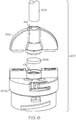
- FIG. 6 is an exploded perspective view of a fluid conduit assembly that is realized as a cap or a connector assembly 600 for a fluid reservoir.
- the connector assembly 600 is generally configured as described above for the connector assembly 214 shown in FIG. 2 . Accordingly, the connector assembly 600 may be provided as component of a disposable infusion set.
- the illustrated embodiment of the connector assembly 600 generally includes, without limitation: a body section 602; a flow path defined in the body section 602; a length of tubing 604 extending from the body section 602; and a gas trapping filter 606.
- FIG. 6 depicts the body section 602 separated into two constituent parts: a lower body section 602a; and an upper body section 602b.
- the lower body section 602a can be affixed to the upper body section 602b (for example, by sonic welding or using an adhesive) after installing the gas trapping filter 606 into a retaining cavity 610 formed within the lower body section 602a.
- the body section 602 can be fabricated as a one-piece component by molding a suitable material while encapsulating the gas trapping filter 606 inside the body section 602.
- the lower body section 602a is suitably configured to receive a fluid reservoir, e.g., by a threaded engagement, a snap fit, tabs, or the like.
- the tubing 604 is physically and fluidly coupled to the upper body section 602b such that the tubing 604 is in fluid communication with the flow path. This allows the tubing 604 to carry fluid from the body section 602 during a fluid delivery operation.
- the flow path much of which is hidden from view in FIG.
- a hollow needle that penetrates a septum of the fluid reservoir; an internal space, chamber, or conduit of the lower body section 602a, which is upstream of the gas trapping filter 606; and an internal space, chamber, or conduit 614 of the upper body section 602b, which is downstream of the gas trapping filter 606.
- the flow path continues into the tubing 604, which is connected to the upper body section 602b.
- the gas trapping filter 606 is secured within the body section 602 such that it is positioned in the flow path of the medication fluid. During a fluid delivery operation, the medication fluid is forced out of the fluid reservoir and into the hollow needle (not shown in FIG. 6 ). The distal end of the hollow needle terminates at a location that is upstream of the gas trapping filter 606. This positioning ensures that the medication fluid can be filtered and otherwise treated by the gas trapping filter 606 before it exits the connector assembly 600. As explained above, the gas trapping filter 606 is suitably configured to reduce the amount of air bubbles in the downstream medication fluid, and optionally can reduce the amount of particulates in the downstream medication fluid.
- FIG. 6 arrangement in which the gas trapping filter is configured as a round "pill" shape. In other words a cylinder axially aligned with the retaining cavity and with a diameter to height ration greater than unity.
- the Fig 6 arrangement has a diameter to height ration of 5:1.
- the gas trapping filter of the Figure 6 arrangement can be composed of any of the materials listed above for the gas trapping filter of the Figure 4 arrangement, or any combination thereof.
- the gas trapping filter presents a large surface area in both the upstream and the downstream directions than the cross-sectional area of the tubing 604.
- the filter has a large working area, and also a large capacity to hold gas and, if required, particulates.
- the filter is part of a disposable part of the apparatus as a whole, i.e. the cap or connector assembly for the fluid reservoir which is, in turn, connected via a tubing to the infusion unit, the device need only have a fairly short life, thus no provision need be made for the removal of the gas collected or of any particulate material that may have accumulated.
- the filter is situated at a position in the flow path where a high wall rigidity is provided as the cap needs to be manually gripped and turned to undo the reservoir from the infusion pump.
- a greater diameter can be provided, and the gas trapping filter can be housed within this manual grip section, thus protecting it from damage.
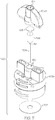
- FIG. 7 is an exploded perspective view of another embodiment of a fluid conduit assembly 700 that is realized as a cap for a fluid reservoir.
- the assembly 700 shares some elements and features with the assembly 600 and, therefore, common elements and features will not be redundantly described here in the context of the assembly 700.
- the connector assembly 700 may be provided as component of a disposable infusion set.
- the illustrated embodiment of the connector assembly 700 generally includes, without limitation: a body section 602 (having a lower body section 602a and an upper body section 602b); a venting membrane 702; a hollow needle 704; a gas trapping filter 706; and a reservoir membrane 708. These components can be assembled together in the manner generally described above for the assembly 600.
- the venting membrane 702 can be affixed to the upper interior surface of the lower body section 602a such that the venting membrane 702 covers one or more vent holes 710 formed in the top portion of the lower body section 602a.
- the vent holes 710 facilitate venting of the reservoir chamber that resides in the housing of the fluid infusion device (see, for example, FIG. 2 ).
- the hollow needle 704 can be affixed to the lower body section 602a such that the downstream end 712 of the hollow needle 704 resides below or within the gas trapping filter 706 after the fluid conduit assembly 700 is fabricated. The positioning of the downstream end 712 is important to ensure that the medication fluid is forced through the gas trapping filter 706 during fluid delivery operations.
- the reservoir membrane 708 can be affixed within a cavity formed in the upper body section 602b (the cavity is hidden from view in FIG. 7 ).
- the reservoir membrane 708 is at least partially hydrophilic to allow the medication fluid to pass during fluid delivery operations.
- the gas trapping filter 706 is secured within the body section 602 such that it is positioned in the flow path of the medication fluid.
- the gas trapping filter 706 may be positioned between the reservoir membrane 708 and the downstream end 712 of the hollow needle 704.
- the gas trapping filter for example the filter 706 in the Figure 7 arrangement or the filter 606 in the Figure 6 arrangement may be is realized as a foam, sponge, or felt fiber composite material.
- the material used for the gas trapping filters 606 and 706 may include, without limitation: polyvinyl acetate (PVA); polyvinyl alcohol; polyester (PET); polycarbonate; polyurethane; polyethyl sulfone; collagen; polycaprolactone; or any combination thereof.
- a felt-based gas trapping filters 606 and 706 have a pore size within the range of about one to 100 microns, and preferably within the range of about 20 to 40 microns.
- a sponge-based gas trapping filter 606 or 706 may have a pore size within the range of about 20 to 1000 microns. Regardless of their composition and configuration, the gas trapping filters 606 and 706 are suitably configured to reduce the amount of air bubbles in the downstream medication fluid, and preferably also to reduce the amount of particulates in the downstream medication fluid.
- the FIG. 7 arrangement takes advantage of the relatively tall body of the wing-like extension of the reservoir cap, which is provided for the user to grip and turn the cap.
- the gas trapping filter is configured as a cylinder co-axial with the flow path.
- This arrangement addresses the problem of how to accommodate a relatively large and, hence, low resistance gas trapping filter with a high gas retaining capacity.
- the solution here is to configure the gas trapping filter 706 as a tall cylinder, in other words the diameter to height ratio should be less than or equal to unity. For example the diameter to height ration in the Fig 7 arrangement is 83%.
- the filter may be fed from a central cavity and exhausted partially via its outer curved surface.
- the additional membrane 708 ensures that only medicinal fluid passes into the upper body section, the gas trapping filter 706 retaining any bubbles.
Landscapes
- Health & Medical Sciences (AREA)
- Heart & Thoracic Surgery (AREA)
- Hematology (AREA)
- Anesthesiology (AREA)
- Biomedical Technology (AREA)
- Engineering & Computer Science (AREA)
- Life Sciences & Earth Sciences (AREA)
- Animal Behavior & Ethology (AREA)
- General Health & Medical Sciences (AREA)
- Public Health (AREA)
- Veterinary Medicine (AREA)
- Vascular Medicine (AREA)
- Emergency Medicine (AREA)
- Pulmonology (AREA)
- Infusion, Injection, And Reservoir Apparatuses (AREA)
Claims (13)
- Capuchon (600, 700) destiné à un réservoir d'un fluide médicinal qui fournit un trajet d'écoulement de fluide pour le fluide médicinal vers le tube (604) utilisé pour administrer ledit fluide à un utilisateur ; ledit capuchon (600, 700) comprenant :une section de corps inférieure (602a) conçue pour pouvoir entrer en prise avec le réservoir et ayant un alésage axial pour conduire le fluide médicinal hors du réservoir ;une section de corps supérieure (602b) ayant un alésage axial (614) pour la liaison au niveau d'une extrémité au tube (604), l'alésage axial (614) de la section de corps supérieure (602b) étant en communication fluidique avec l'alésage axial de la section de corps inférieure (602a) pour recevoir le fluide de médicament par l'intermédiaire d'une chambre interne (610) ; dans lequelun filtre de piégeage de gaz (606, 706) est logé à l'intérieur de la chambre interne (610) et est caractérisé en ce qu'il est conçu pour retenir des bulles de gaz, empêchant ainsi ledit gaz de quitter la chambre interne (610) ;le filtre de piégeage de gaz (606, 706) étant réalisé sous la forme d'un matériau composite en mousse, en éponge ou en fibres de feutre.
- Capuchon selon la revendication 1, dans lequel la section de corps inférieure (602a) comporte une aiguille creuse en amont disposée axialement à l'intérieur de l'alésage axial et en communication fluidique avec la chambre interne (610) en amont du filtre de piégeage de gaz pour reconstituer un septum dans le réservoir et conduire le fluide médicinal de celui-ci vers la chambre interne (610).
- Capuchon selon la revendication 1 ou 2, dans lequel le filtre de piégeage de gaz (606, 706) est adapté pour avoir une ou plusieurs des fonctions supplémentaires suivantes :a. le filtrage des particules ;b. l'adsorption ou l'absorption d'huile de silicone ;c. la formation d'un dépôt d'un médicament de telle sorte que le médicament est libéré dans le fluide médicinal lors de son passage.
- Capuchon selon la revendication 1 ou 2, dans lequel le filtre de piégeage de gaz (606, 706) est adapté pour filtrer les particules, et a une taille de pore dans la plage allant de 0,45 à 5,00 microns.
- Capuchon selon l'une quelconque des revendications 1 à 4, dans lequel le filtre de piégeage de gaz (606, 706) est en feutre et a une taille de pore dans la plage allant de 1 à 100 micromètres, et de préférence allant de 20 à 40 micromètres, ou est en éponge avec une taille de pore dans la plage allant de 20 micromètres à 1 millimètre.
- Capuchon selon l'une quelconque des revendications 1 à 5, dans lequel la section de corps inférieure (602a) et la section de corps supérieure (602b) sont solidaires l'une de l'autre.
- Capuchon selon l'une quelconque des revendications 1 à 6, dans lequel le filtre de piégeage de gaz (606, 706) comprend un composant cylindrique discret disposé axialement dans la chambre interne et ayant un rapport diamètre-hauteur supérieur à l'unité, de préférence 5 : 1 ou supérieur.
- Capuchon selon la revendication 7, dans lequel le filtre de piégeage de gaz (606) est maintenu dans la chambre interne (610) par une première bride annulaire faisant partie de la section de corps inférieure (602a), et une seconde bride annulaire faisant partie de la section de corps supérieure (602b), au moins l'une desdites brides annulaires assurant également l'étanchéité contre les marges des surfaces principales respectives du filtre de piégeage de gaz (606), garantissant que l'écoulement de fluide de médicament se fait à travers une région centrale du filtre.
- Capuchon selon l'une quelconque des revendications 1 à 6, dans lequel le filtre de piégeage de gaz (706) comprend un composant cylindrique discret disposé axialement dans la chambre interne (610) et ayant un rapport diamètre-hauteur inférieur ou égal à l'unité.
- Capuchon selon la revendication 9, dans lequel une membrane hydrophile (708) est prévue séparant la chambre interne (610) de l'alésage de la section de corps supérieure (602b).
- Capuchon selon l'une quelconque des revendications 1 à 10, dans lequel la section de corps supérieure (602b) présente une préhension manuelle radialement vers l'extérieur à partir du filtre de piégeage de gaz, permettant au capuchon (600) d'être facilement tourné à la main autour de son axe longitudinal.
- Système de distribution de fluide pour administrer un fluide médicinal à un utilisateur comprenant : une pompe à perfusion (202) comportant un réservoir du fluide médicinal, ledit réservoir ayant un capuchon (214) selon l'une quelconque des revendications 1 à 11 ;
une longueur de tube (210, 604) reliée au niveau d'une extrémité proximale à l'alésage axial (614) de la section de corps supérieure (602b) du capuchon (600, 700), et au niveau d'une extrémité distale à une unité de perfusion (212) ayant une canule pour permettre au fluide du réservoir d'être perfusé dans le corps de l'utilisateur pendant le fonctionnement de la pompe (202). - Ensemble de distribution de fluide jetable comprenant un réservoir de fluide médicinal, ledit réservoir ayant un capuchon (214, 600, 700) selon la revendication 11 ou la revendication 12 lorsqu'elle dépend de la revendication 11, le capuchon (214, 600, 700) en outre étant pourvu d'un raccord de filetage ou à baïonette pour monter de manière amovible le réservoir dans une pompe à perfusion, l'ensemble pouvant être détaché pour être éliminé en tournant le capuchon (214, 600, 700) par l'intermédiaire de ladite préhension manuelle.
Priority Applications (3)
| Application Number | Priority Date | Filing Date | Title |
|---|---|---|---|
| EP24217771.5A EP4512442A3 (fr) | 2014-10-07 | 2015-06-25 | Ensemble conduit de fluide ayant un filtre de capture de gaz dans le trajet d'écoulement de fluide |
| EP21198501.5A EP3954413B1 (fr) | 2014-10-07 | 2015-06-25 | Ensemble conduit de fluide ayant un filtre de capture de gaz dans le trajet d'écoulement de fluide |
| DK21198501.5T DK3954413T3 (da) | 2014-10-07 | 2015-06-25 | Fluidledningssamling med gasopfangningsfilter i fluidstrømningsbanen |
Applications Claiming Priority (2)
| Application Number | Priority Date | Filing Date | Title |
|---|---|---|---|
| US14/508,934 US10279126B2 (en) | 2014-10-07 | 2014-10-07 | Fluid conduit assembly with gas trapping filter in the fluid flow path |
| PCT/US2015/037796 WO2016057093A1 (fr) | 2014-10-07 | 2015-06-25 | Ensemble conduit de fluide ayant un filtre de capture de gaz dans le trajet d'écoulement de fluide |
Related Child Applications (3)
| Application Number | Title | Priority Date | Filing Date |
|---|---|---|---|
| EP24217771.5A Division EP4512442A3 (fr) | 2014-10-07 | 2015-06-25 | Ensemble conduit de fluide ayant un filtre de capture de gaz dans le trajet d'écoulement de fluide |
| EP21198501.5A Division EP3954413B1 (fr) | 2014-10-07 | 2015-06-25 | Ensemble conduit de fluide ayant un filtre de capture de gaz dans le trajet d'écoulement de fluide |
| EP21198501.5A Division-Into EP3954413B1 (fr) | 2014-10-07 | 2015-06-25 | Ensemble conduit de fluide ayant un filtre de capture de gaz dans le trajet d'écoulement de fluide |
Publications (2)
| Publication Number | Publication Date |
|---|---|
| EP3204094A1 EP3204094A1 (fr) | 2017-08-16 |
| EP3204094B1 true EP3204094B1 (fr) | 2021-12-08 |
Family
ID=53511045
Family Applications (3)
| Application Number | Title | Priority Date | Filing Date |
|---|---|---|---|
| EP24217771.5A Pending EP4512442A3 (fr) | 2014-10-07 | 2015-06-25 | Ensemble conduit de fluide ayant un filtre de capture de gaz dans le trajet d'écoulement de fluide |
| EP15734028.2A Active EP3204094B1 (fr) | 2014-10-07 | 2015-06-25 | Ensemble conduit de fluide ayant un filtre de capture de gaz dans le trajet d'écoulement de fluide |
| EP21198501.5A Active EP3954413B1 (fr) | 2014-10-07 | 2015-06-25 | Ensemble conduit de fluide ayant un filtre de capture de gaz dans le trajet d'écoulement de fluide |
Family Applications Before (1)
| Application Number | Title | Priority Date | Filing Date |
|---|---|---|---|
| EP24217771.5A Pending EP4512442A3 (fr) | 2014-10-07 | 2015-06-25 | Ensemble conduit de fluide ayant un filtre de capture de gaz dans le trajet d'écoulement de fluide |
Family Applications After (1)
| Application Number | Title | Priority Date | Filing Date |
|---|---|---|---|
| EP21198501.5A Active EP3954413B1 (fr) | 2014-10-07 | 2015-06-25 | Ensemble conduit de fluide ayant un filtre de capture de gaz dans le trajet d'écoulement de fluide |
Country Status (6)
| Country | Link |
|---|---|
| US (4) | US10279126B2 (fr) |
| EP (3) | EP4512442A3 (fr) |
| CN (1) | CN107073229B (fr) |
| CA (1) | CA2963512C (fr) |
| DK (2) | DK3954413T3 (fr) |
| WO (1) | WO2016057093A1 (fr) |
Cited By (1)
| Publication number | Priority date | Publication date | Assignee | Title |
|---|---|---|---|---|
| WO2026010614A1 (fr) * | 2024-07-01 | 2026-01-08 | Koru Medical Systems, Inc. | Système et procédé pour pavillon d'aiguille ventilé pour perfusion |
Families Citing this family (20)
| Publication number | Priority date | Publication date | Assignee | Title |
|---|---|---|---|---|
| WO2012131044A1 (fr) | 2011-03-30 | 2012-10-04 | Unomedical A/S | Dispositif d'introduction par voie sous-cutanée d'un dispositif médical |
| US10517892B2 (en) | 2013-10-22 | 2019-12-31 | Medtronic Minimed, Inc. | Methods and systems for inhibiting foreign-body responses in diabetic patients |
| US10279126B2 (en) | 2014-10-07 | 2019-05-07 | Medtronic Minimed, Inc. | Fluid conduit assembly with gas trapping filter in the fluid flow path |
| US10589038B2 (en) | 2016-04-27 | 2020-03-17 | Medtronic Minimed, Inc. | Set connector systems for venting a fluid reservoir |
| US10086134B2 (en) | 2016-05-26 | 2018-10-02 | Medtronic Minimed, Inc. | Systems for set connector assembly with lock |
| US10086133B2 (en) | 2016-05-26 | 2018-10-02 | Medtronic Minimed, Inc. | Systems for set connector assembly with lock |
| US9968737B2 (en) | 2016-05-26 | 2018-05-15 | Medtronic Minimed, Inc. | Systems for set connector assembly with lock |
| US11197949B2 (en) | 2017-01-19 | 2021-12-14 | Medtronic Minimed, Inc. | Medication infusion components and systems |
| EP3576824B1 (fr) * | 2017-01-31 | 2022-04-20 | Medtronic MiniMed, Inc. | Dispositifs de perfusion ambulatoires et ensembles filtres à utiliser avec ceux-ci |
| CN111665678A (zh) * | 2017-09-19 | 2020-09-15 | 海信视像科技股份有限公司 | 一种水冷散热系统以及投影机 |
| WO2020156666A1 (fr) * | 2019-01-30 | 2020-08-06 | Gasgon Medical | Dispositif à piéger des bulles |
| US11957542B2 (en) | 2020-04-30 | 2024-04-16 | Automed Patent Holdco, Llc | Sensing complete injection for animal injection device |
| CN111939350A (zh) * | 2020-07-14 | 2020-11-17 | 山东中保康医疗器具有限公司 | 离心袋式血液成分分离器及其在返血流程中的气体截留方法 |
| WO2022047199A1 (fr) * | 2020-08-28 | 2022-03-03 | Capillary Biomedical, Inc. | Ensemble de perfusion d'insuline |
| AU2021411950A1 (en) | 2020-12-30 | 2023-07-06 | Convatec Technologies Inc. | Surface treatment system and method for subcutaneous device |
| US20230149637A1 (en) * | 2021-11-12 | 2023-05-18 | Medtronic Minimed, Inc. | Fluid reservoir cap with gas trapping filter and associated retaining feature |
| WO2025073980A1 (fr) * | 2023-10-06 | 2025-04-10 | Unomedical A/S | Raccord de tube |
| WO2025073976A1 (fr) * | 2023-10-06 | 2025-04-10 | Unomedical A/S | Élément de raccordement de tube avec filtre pour un raccord de perfusion |
| WO2025073978A1 (fr) * | 2023-10-06 | 2025-04-10 | Unomedical A/S | Raccord de tube |
| US20250242106A1 (en) | 2024-01-26 | 2025-07-31 | Medtronic Minimed, Inc. | Fluid reservoirs and associated devices and methods |
Citations (7)
| Publication number | Priority date | Publication date | Assignee | Title |
|---|---|---|---|---|
| US3631654A (en) * | 1968-10-03 | 1972-01-04 | Pall Corp | Gas purge device |
| US3978857A (en) * | 1972-08-14 | 1976-09-07 | American Hospital Supply Corporation | System with filter for administrating parenteral liquids |
| US20020077598A1 (en) * | 1998-10-29 | 2002-06-20 | Yap Darren Y. K. | Improved fluid reservoir piston |
| US20020173748A1 (en) * | 1998-10-29 | 2002-11-21 | Mcconnell Susan | Reservoir connector |
| US20050161042A1 (en) * | 2004-01-23 | 2005-07-28 | Ric Investments, Llc. | Liquid absorbing filter assembly and system using same |
| EP2229970A1 (fr) * | 2009-03-16 | 2010-09-22 | F. Hoffmann-La Roche AG | Système de débulleur pour un dispositif de pompe à perfusion |
| CN103100131A (zh) * | 2013-03-06 | 2013-05-15 | 陆永会 | 自动排气止液滴斗 |
Family Cites Families (314)
| Publication number | Priority date | Publication date | Assignee | Title |
|---|---|---|---|---|
| US5338157B1 (en) | 1992-09-09 | 1999-11-02 | Sims Deltec Inc | Systems and methods for communicating with ambulat |
| US5935099A (en) | 1992-09-09 | 1999-08-10 | Sims Deltec, Inc. | Drug pump systems and methods |
| US3003500A (en) * | 1955-12-14 | 1961-10-10 | Baxter Laboratories Inc | Intravenous administration equipment |
| US3631847A (en) | 1966-03-04 | 1972-01-04 | James C Hobbs | Method and apparatus for injecting fluid into the vascular system |
| US3650093A (en) * | 1970-01-08 | 1972-03-21 | Pall Corp | Sterile disposable medicament administration system |
| US3827562A (en) * | 1972-03-03 | 1974-08-06 | W Esmond | Filtering device |
| US3882026A (en) * | 1972-08-14 | 1975-05-06 | American Hospital Supply Corp | Hydrophobic filter device for medical liquids |
| US4004587A (en) * | 1975-06-13 | 1977-01-25 | Baxter Travenol Laboratories, Inc. | Parenteral liquid administration set with non-air blocking filter |
| US4013072A (en) * | 1975-11-03 | 1977-03-22 | Baxter Travenol Laboratories, Inc. | Drip chamber for intravenous administration |
| FR2385406A1 (fr) | 1977-03-28 | 1978-10-27 | Akzo Nv | Rein artificiel |
| US4116646A (en) * | 1977-05-20 | 1978-09-26 | Millipore Corporation | Filter unit |
| US4190426A (en) * | 1977-11-30 | 1980-02-26 | Baxter Travenol Laboratories, Inc. | Gas separating and venting filter |
| DE2758368C2 (de) | 1977-12-28 | 1985-10-17 | Siemens AG, 1000 Berlin und 8000 München | Vorrichtung zur vorprogrammierbaren Infusion von Flüssigkeiten |
| US4559037A (en) | 1977-12-28 | 1985-12-17 | Siemens Aktiengesellschaft | Device for the pre-programmable infusion of liquids |
| DE2758467C2 (de) | 1977-12-28 | 1985-04-04 | Siemens AG, 1000 Berlin und 8000 München | Vorrichtung zur vorprogrammierbaren Infusion von Flüssigkeiten |
| FR2444064A1 (fr) | 1978-12-15 | 1980-07-11 | Sodip Sa | Melange de polymere du chlorure de vinyle et de polyetherurethane a groupe amine tertiaire et/ou ammonium, notamment pour objet conforme a usage medical |
| US4731051A (en) | 1979-04-27 | 1988-03-15 | The Johns Hopkins University | Programmable control means for providing safe and controlled medication infusion |
| US4373527B1 (en) | 1979-04-27 | 1995-06-27 | Univ Johns Hopkins | Implantable programmable medication infusion system |
| DE3035670A1 (de) | 1980-09-22 | 1982-04-29 | Siemens AG, 1000 Berlin und 8000 München | Vorrichtung zur infusion von fluessigkeiten in den menschlichen oder tierischen koerper |
| US4459139A (en) * | 1981-09-14 | 1984-07-10 | Gelman Sciences Inc. | Disposable filter device and liquid aspirating system incorporating same |
| US4494950A (en) | 1982-01-19 | 1985-01-22 | The Johns Hopkins University | Plural module medication delivery system |
| US4443218A (en) | 1982-09-09 | 1984-04-17 | Infusaid Corporation | Programmable implantable infusate pump |
| US4826810A (en) | 1983-12-16 | 1989-05-02 | Aoki Thomas T | System and method for treating animal body tissues to improve the dietary fuel processing capabilities thereof |
| US4678408A (en) | 1984-01-06 | 1987-07-07 | Pacesetter Infusion, Ltd. | Solenoid drive apparatus for an external infusion pump |
| US4685903A (en) | 1984-01-06 | 1987-08-11 | Pacesetter Infusion, Ltd. | External infusion pump apparatus |
| US4562751A (en) | 1984-01-06 | 1986-01-07 | Nason Clyde K | Solenoid drive apparatus for an external infusion pump |
| US5100380A (en) | 1984-02-08 | 1992-03-31 | Abbott Laboratories | Remotely programmable infusion system |
| US4550731A (en) | 1984-03-07 | 1985-11-05 | Cordis Corporation | Acquisition circuit for cardiac pacer |
| US4542532A (en) | 1984-03-09 | 1985-09-17 | Medtronic, Inc. | Dual-antenna transceiver |
| US4571244A (en) * | 1984-05-07 | 1986-02-18 | Biogenesis, Inc. | System for removing gas bubbles from liquids |
| CA1254091A (fr) | 1984-09-28 | 1989-05-16 | Vladimir Feingold | Systeme implantable pour la perfusion de medicaments |
| US4781798A (en) | 1985-04-19 | 1988-11-01 | The Regents Of The University Of California | Transparent multi-oxygen sensor array and method of using same |
| US4671288A (en) | 1985-06-13 | 1987-06-09 | The Regents Of The University Of California | Electrochemical cell sensor for continuous short-term use in tissues and blood |
| US5003298A (en) | 1986-01-15 | 1991-03-26 | Karel Havel | Variable color digital display for emphasizing position of decimal point |
| US4755173A (en) | 1986-02-25 | 1988-07-05 | Pacesetter Infusion, Ltd. | Soft cannula subcutaneous injection set |
| US4778451A (en) * | 1986-03-04 | 1988-10-18 | Kamen Dean L | Flow control system using boyle's law |
| US5195986A (en) * | 1986-03-04 | 1993-03-23 | Deka Products Limited Partnership | Integral intravenous fluid delivery device |
| US4731726A (en) | 1986-05-19 | 1988-03-15 | Healthware Corporation | Patient-operated glucose monitor and diabetes management system |
| US4803625A (en) | 1986-06-30 | 1989-02-07 | Buddy Systems, Inc. | Personal health monitor |
| EP0290683A3 (fr) | 1987-05-01 | 1988-12-14 | Diva Medical Systems B.V. | Système et appareil de contrôle médical du diabète |
| US5011468A (en) | 1987-05-29 | 1991-04-30 | Retroperfusion Systems, Inc. | Retroperfusion and retroinfusion control apparatus, system and method |
| US4809697A (en) | 1987-10-14 | 1989-03-07 | Siemens-Pacesetter, Inc. | Interactive programming and diagnostic system for use with implantable pacemaker |
| US5041086A (en) | 1987-12-04 | 1991-08-20 | Pacesetter Infusion, Ltd. | Clinical configuration of multimode medication infusion system |
| US5025374A (en) | 1987-12-09 | 1991-06-18 | Arch Development Corp. | Portable system for choosing pre-operative patient test |
| US4898578A (en) | 1988-01-26 | 1990-02-06 | Baxter International Inc. | Drug infusion system with calculator |
| CA1322284C (fr) | 1988-03-14 | 1993-09-21 | Robert K. Mitchell | Arbre a cames moule |
| GB2218831A (en) | 1988-05-17 | 1989-11-22 | Mark John Newland | Personal medical apparatus |
| US5153827A (en) | 1989-01-30 | 1992-10-06 | Omni-Flow, Inc. | An infusion management and pumping system having an alarm handling system |
| US5264105A (en) | 1989-08-02 | 1993-11-23 | Gregg Brian A | Enzyme electrodes |
| US5264104A (en) | 1989-08-02 | 1993-11-23 | Gregg Brian A | Enzyme electrodes |
| US5262035A (en) | 1989-08-02 | 1993-11-16 | E. Heller And Company | Enzyme electrodes |
| US5101814A (en) | 1989-08-11 | 1992-04-07 | Palti Yoram Prof | System for monitoring and controlling blood glucose |
| US5050612A (en) | 1989-09-12 | 1991-09-24 | Matsumura Kenneth N | Device for computer-assisted monitoring of the body |
| EP0433485B1 (fr) * | 1989-12-21 | 1993-05-19 | Siemens Aktiengesellschaft | Dispositif pour remplir ou recharger de médicaments liquides un dispositif de dosage de médicaments implantable |
| US5108819A (en) | 1990-02-14 | 1992-04-28 | Eli Lilly And Company | Thin film electrical component |
| US5097122A (en) | 1990-04-16 | 1992-03-17 | Pacesetter Infusion, Ltd. | Medication infusion system having optical motion sensor to detect drive mechanism malfunction |
| US5080653A (en) | 1990-04-16 | 1992-01-14 | Pacesetter Infusion, Ltd. | Infusion pump with dual position syringe locator |
| US5165407A (en) | 1990-04-19 | 1992-11-24 | The University Of Kansas | Implantable glucose sensor |
| US5078683A (en) | 1990-05-04 | 1992-01-07 | Block Medical, Inc. | Programmable infusion system |
| US5593852A (en) | 1993-12-02 | 1997-01-14 | Heller; Adam | Subcutaneous glucose electrode |
| JPH04278450A (ja) | 1991-03-04 | 1992-10-05 | Adam Heller | バイオセンサー及び分析物を分析する方法 |
| US5262305A (en) | 1991-03-04 | 1993-11-16 | E. Heller & Company | Interferant eliminating biosensors |
| US5247434A (en) | 1991-04-19 | 1993-09-21 | Althin Medical, Inc. | Method and apparatus for kidney dialysis |
| US5322063A (en) | 1991-10-04 | 1994-06-21 | Eli Lilly And Company | Hydrophilic polyurethane membranes for electrochemical glucose sensors |
| US5308333A (en) * | 1991-12-06 | 1994-05-03 | Baxter International Inc. | Air eliminating intravenous infusion pump set |
| US5284140A (en) | 1992-02-11 | 1994-02-08 | Eli Lilly And Company | Acrylic copolymer membranes for biosensors |
| JPH08275927A (ja) | 1992-02-13 | 1996-10-22 | Seta:Kk | 在宅医療システム及びこのシステムに用いる医療装置 |
| US5788669A (en) | 1995-11-22 | 1998-08-04 | Sims Deltec, Inc. | Pump tracking system |
| US5376070A (en) | 1992-09-29 | 1994-12-27 | Minimed Inc. | Data transfer system for an infusion pump |
| US5940801A (en) | 1994-04-26 | 1999-08-17 | Health Hero Network, Inc. | Modular microprocessor-based diagnostic measurement apparatus and method for psychological conditions |
| US5997476A (en) | 1997-03-28 | 1999-12-07 | Health Hero Network, Inc. | Networked system for interactive communication and remote monitoring of individuals |
| US5918603A (en) | 1994-05-23 | 1999-07-06 | Health Hero Network, Inc. | Method for treating medical conditions using a microprocessor-based video game |
| US6101478A (en) | 1997-04-30 | 2000-08-08 | Health Hero Network | Multi-user remote health monitoring system |
| US5897493A (en) | 1997-03-28 | 1999-04-27 | Health Hero Network, Inc. | Monitoring system for remotely querying individuals |
| US5832448A (en) | 1996-10-16 | 1998-11-03 | Health Hero Network | Multiple patient monitoring system for proactive health management |
| US5913310A (en) | 1994-05-23 | 1999-06-22 | Health Hero Network, Inc. | Method for diagnosis and treatment of psychological and emotional disorders using a microprocessor-based video game |
| US5933136A (en) | 1996-12-23 | 1999-08-03 | Health Hero Network, Inc. | Network media access control system for encouraging patient compliance with a treatment plan |
| US5956501A (en) | 1997-01-10 | 1999-09-21 | Health Hero Network, Inc. | Disease simulation system and method |
| US5307263A (en) | 1992-11-17 | 1994-04-26 | Raya Systems, Inc. | Modular microprocessor-based health monitoring system |
| US5960403A (en) | 1992-11-17 | 1999-09-28 | Health Hero Network | Health management process control system |
| US5899855A (en) | 1992-11-17 | 1999-05-04 | Health Hero Network, Inc. | Modular microprocessor-based health monitoring system |
| US5879163A (en) | 1996-06-24 | 1999-03-09 | Health Hero Network, Inc. | On-line health education and feedback system using motivational driver profile coding and automated content fulfillment |
| US5371687A (en) | 1992-11-20 | 1994-12-06 | Boehringer Mannheim Corporation | Glucose test data acquisition and management system |
| ZA938555B (en) | 1992-11-23 | 1994-08-02 | Lilly Co Eli | Technique to improve the performance of electrochemical sensors |
| US5545143A (en) | 1993-01-21 | 1996-08-13 | T. S. I. Medical | Device for subcutaneous medication delivery |
| US5299571A (en) | 1993-01-22 | 1994-04-05 | Eli Lilly And Company | Apparatus and method for implantation of sensors |
| DK25793A (da) | 1993-03-09 | 1994-09-10 | Pharma Plast Int As | Infusionssæt til intermitterende eller kontinuerlig indgivelse af et terapeutisk middel |
| US5357427A (en) | 1993-03-15 | 1994-10-18 | Digital Equipment Corporation | Remote monitoring of high-risk patients using artificial intelligence |
| US5350411A (en) | 1993-06-28 | 1994-09-27 | Medtronic, Inc. | Pacemaker telemetry system |
| US5368562A (en) | 1993-07-30 | 1994-11-29 | Pharmacia Deltec, Inc. | Systems and methods for operating ambulatory medical devices such as drug delivery devices |
| DE4329229A1 (de) | 1993-08-25 | 1995-03-09 | Meditech Medizintechnik Gmbh | Adaptive kontrollierte Pumpensteuerung, insbesondere zur Adaptiven Patientenkontrollierten Analgesie (APCA) |
| US5791344A (en) | 1993-11-19 | 1998-08-11 | Alfred E. Mann Foundation For Scientific Research | Patient monitoring system |
| US5497772A (en) | 1993-11-19 | 1996-03-12 | Alfred E. Mann Foundation For Scientific Research | Glucose monitoring system |
| US5594638A (en) | 1993-12-29 | 1997-01-14 | First Opinion Corporation | Computerized medical diagnostic system including re-enter function and sensitivity factors |
| US5660176A (en) | 1993-12-29 | 1997-08-26 | First Opinion Corporation | Computerized medical diagnostic and treatment advice system |
| FR2716286A1 (fr) | 1994-02-16 | 1995-08-18 | Debiotech Sa | Installation de surveillance à distance d'équipements commandables. |
| US5543326A (en) | 1994-03-04 | 1996-08-06 | Heller; Adam | Biosensor including chemically modified enzymes |
| US5630710A (en) | 1994-03-09 | 1997-05-20 | Baxter International Inc. | Ambulatory infusion pump |
| US5536249A (en) | 1994-03-09 | 1996-07-16 | Visionary Medical Products, Inc. | Pen-type injector with a microprocessor and blood characteristic monitor |
| US5391250A (en) | 1994-03-15 | 1995-02-21 | Minimed Inc. | Method of fabricating thin film sensors |
| US5390671A (en) | 1994-03-15 | 1995-02-21 | Minimed Inc. | Transcutaneous sensor insertion set |
| US5569186A (en) | 1994-04-25 | 1996-10-29 | Minimed Inc. | Closed loop infusion pump system with removable glucose sensor |
| US5370622A (en) | 1994-04-28 | 1994-12-06 | Minimed Inc. | Proctective case for a medication infusion pump |
| US5482473A (en) | 1994-05-09 | 1996-01-09 | Minimed Inc. | Flex circuit connector |
| US5704366A (en) | 1994-05-23 | 1998-01-06 | Enact Health Management Systems | System for monitoring and reporting medical measurements |
| US5582593A (en) | 1994-07-21 | 1996-12-10 | Hultman; Barry W. | Ambulatory medication delivery system |
| US5569187A (en) | 1994-08-16 | 1996-10-29 | Texas Instruments Incorporated | Method and apparatus for wireless chemical supplying |
| US5505709A (en) | 1994-09-15 | 1996-04-09 | Minimed, Inc., A Delaware Corporation | Mated infusion pump and syringe |
| US5687734A (en) | 1994-10-20 | 1997-11-18 | Hewlett-Packard Company | Flexible patient monitoring system featuring a multiport transmitter |
| IE72524B1 (en) | 1994-11-04 | 1997-04-23 | Elan Med Tech | Analyte-controlled liquid delivery device and analyte monitor |
| US5522769A (en) | 1994-11-17 | 1996-06-04 | W. L. Gore & Associates, Inc. | Gas-permeable, liquid-impermeable vent cover |
| US5573506A (en) | 1994-11-25 | 1996-11-12 | Block Medical, Inc. | Remotely programmable infusion system |
| US6749586B2 (en) | 1994-11-25 | 2004-06-15 | I-Flow Corporation | Remotely programmable infusion system |
| US5685844A (en) | 1995-01-06 | 1997-11-11 | Abbott Laboratories | Medicinal fluid pump having multiple stored protocols |
| US5586553A (en) | 1995-02-16 | 1996-12-24 | Minimed Inc. | Transcutaneous sensor insertion set |
| US5814015A (en) | 1995-02-24 | 1998-09-29 | Harvard Clinical Technology, Inc. | Infusion pump for at least one syringe |
| EP0900095A1 (fr) * | 1995-03-22 | 1999-03-10 | Travenol Laboratories (Israel) Ltd. | Chambre de goutte-a-goutte pour perfusion intraveineuse |
| US5609060A (en) | 1995-04-28 | 1997-03-11 | Dentsleeve Pty Limited | Multiple channel perfused manometry apparatus and a method of operation of such a device |
| US5772635A (en) | 1995-05-15 | 1998-06-30 | Alaris Medical Systems, Inc. | Automated infusion system with dose rate calculator |
| US5665065A (en) | 1995-05-26 | 1997-09-09 | Minimed Inc. | Medication infusion device with blood glucose data input |
| US6018289A (en) | 1995-06-15 | 2000-01-25 | Sekura; Ronald D. | Prescription compliance device and method of using device |
| US5750926A (en) | 1995-08-16 | 1998-05-12 | Alfred E. Mann Foundation For Scientific Research | Hermetically sealed electrical feedthrough for use with implantable electronic devices |
| US5754111A (en) | 1995-09-20 | 1998-05-19 | Garcia; Alfredo | Medical alerting system |
| US6689265B2 (en) | 1995-10-11 | 2004-02-10 | Therasense, Inc. | Electrochemical analyte sensors using thermostable soybean peroxidase |
| US5972199A (en) | 1995-10-11 | 1999-10-26 | E. Heller & Company | Electrochemical analyte sensors using thermostable peroxidase |
| US5665222A (en) | 1995-10-11 | 1997-09-09 | E. Heller & Company | Soybean peroxidase electrochemical sensor |
| DE69633573T2 (de) | 1995-11-22 | 2005-10-06 | Medtronic MiniMed, Inc., Northridge | Detektion von biologischen molekülen unter verwendung von chemischer amplifikation und optischem sensor |
| US6766183B2 (en) | 1995-11-22 | 2004-07-20 | Medtronic Minimed, Inc. | Long wave fluorophore sensor compounds and other fluorescent sensor compounds in polymers |
| AUPN707195A0 (en) | 1995-12-12 | 1996-01-11 | University Of Melbourne, The | Field programmable intravenous infusion system |
| FI118509B (fi) | 1996-02-12 | 2007-12-14 | Nokia Oyj | Menetelmä ja laitteisto potilaan veren glukoosipitoisuuden ennustamiseksi |
| FR2748588B1 (fr) | 1996-05-07 | 1998-08-07 | Soc Et Tech Set | Dispositif comportant au moins un reseau de neurones pour determiner la quantite d'une substance a administrer a un patient, notamment de l'insuline |
| US5861018A (en) | 1996-05-28 | 1999-01-19 | Telecom Medical Inc. | Ultrasound transdermal communication system and method |
| US5807336A (en) | 1996-08-02 | 1998-09-15 | Sabratek Corporation | Apparatus for monitoring and/or controlling a medical device |
| US5885245A (en) | 1996-08-02 | 1999-03-23 | Sabratek Corporation | Medical apparatus with remote virtual input device |
| US5800490A (en) | 1996-11-07 | 1998-09-01 | Patz; Herbert Samuel | Lightweight portable cooling or heating device with multiple applications |
| CA2271710A1 (fr) | 1996-11-08 | 1998-05-14 | Linda L. Roman | Systeme pour assistance et soins de sante complets |
| WO1998024358A2 (fr) | 1996-12-04 | 1998-06-11 | Enact Health Management Systems | Systeme pour telecharger et transmettre des renseignements medicaux |
| US6043437A (en) | 1996-12-20 | 2000-03-28 | Alfred E. Mann Foundation | Alumina insulation for coating implantable components and other microminiature devices |
| US6032119A (en) | 1997-01-16 | 2000-02-29 | Health Hero Network, Inc. | Personalized display of health information |
| CZ349198A3 (cs) | 1997-01-31 | 1999-04-14 | Silverline Power Conversion, Llc | Nepřerušitelný napájecí zdroj |
| US6607509B2 (en) | 1997-12-31 | 2003-08-19 | Medtronic Minimed, Inc. | Insertion device for an insertion set and method of using the same |
| WO1998035225A1 (fr) | 1997-02-06 | 1998-08-13 | E. Heller & Company | DETECTEUR D'UN FAIBLE VOLUME D'ANALYTE $i(IN VITRO) |
| US6009339A (en) | 1997-02-27 | 1999-12-28 | Terumo Cardiovascular Systems Corporation | Blood parameter measurement device |
| AU8938598A (en) | 1997-03-27 | 1999-04-23 | Medtronic, Inc. | Implantable Medical Device Remote Expert Communications System For Coordina ted Implant And Follow-Up |
| US5960085A (en) | 1997-04-14 | 1999-09-28 | De La Huerga; Carlos | Security badge for automated access control and secure data gathering |
| DE19717107B4 (de) | 1997-04-23 | 2005-06-23 | Disetronic Licensing Ag | System aus Behältnis und Antriebsvorrichtung für einen Kolben, der in dem ein Medikamentfluid enthaltenden Behältnis gehalten ist |
| US6186982B1 (en) | 1998-05-05 | 2001-02-13 | Elan Corporation, Plc | Subcutaneous drug delivery device with improved filling system |
| US5779665A (en) | 1997-05-08 | 1998-07-14 | Minimed Inc. | Transdermal introducer assembly |
| TW357517B (en) | 1997-05-29 | 1999-05-01 | Koji Akai | Monitoring system |
| US5954643A (en) | 1997-06-09 | 1999-09-21 | Minimid Inc. | Insertion set for a transcutaneous sensor |
| US6558351B1 (en) | 1999-06-03 | 2003-05-06 | Medtronic Minimed, Inc. | Closed loop system for controlling insulin infusion |
| WO1998059487A1 (fr) | 1997-06-23 | 1998-12-30 | Enact Health Management Systems | Systeme ameliore permettant de telecharger et de communiquer des informations medicales |
| US6130620A (en) | 1997-08-11 | 2000-10-10 | Electronic Monitoring Systems, Inc. | Remote monitoring system |
| AU8826498A (en) | 1997-08-22 | 1999-03-16 | Apex Inc. | Remote computer control system |
| US6259937B1 (en) | 1997-09-12 | 2001-07-10 | Alfred E. Mann Foundation | Implantable substrate sensor |
| US5999848A (en) | 1997-09-12 | 1999-12-07 | Alfred E. Mann Foundation | Daisy chainable sensors and stimulators for implantation in living tissue |
| US6071391A (en) | 1997-09-12 | 2000-06-06 | Nok Corporation | Enzyme electrode structure |
| US5999849A (en) | 1997-09-12 | 1999-12-07 | Alfred E. Mann Foundation | Low power rectifier circuit for implantable medical device |
| US5917346A (en) | 1997-09-12 | 1999-06-29 | Alfred E. Mann Foundation | Low power current to frequency converter circuit for use in implantable sensors |
| WO1999017819A1 (fr) | 1997-10-02 | 1999-04-15 | Micromed Technology, Inc. | Systeme de pompage implantable |
| US6088608A (en) | 1997-10-20 | 2000-07-11 | Alfred E. Mann Foundation | Electrochemical sensor and integrity tests therefor |
| US6081736A (en) | 1997-10-20 | 2000-06-27 | Alfred E. Mann Foundation | Implantable enzyme-based monitoring systems adapted for long term use |
| US6119028A (en) | 1997-10-20 | 2000-09-12 | Alfred E. Mann Foundation | Implantable enzyme-based monitoring systems having improved longevity due to improved exterior surfaces |
| FI107080B (fi) | 1997-10-27 | 2001-05-31 | Nokia Mobile Phones Ltd | Mittauslaite |
| US6579690B1 (en) | 1997-12-05 | 2003-06-17 | Therasense, Inc. | Blood analyte monitoring through subcutaneous measurement |
| US6134461A (en) | 1998-03-04 | 2000-10-17 | E. Heller & Company | Electrochemical analyte |
| US6103033A (en) | 1998-03-04 | 2000-08-15 | Therasense, Inc. | Process for producing an electrochemical biosensor |
| EP1061972A1 (fr) | 1998-03-16 | 2000-12-27 | Medtronic, Inc. | Systeme et constituants hemostatiques pour circuit extracorporel |
| US5904708A (en) | 1998-03-19 | 1999-05-18 | Medtronic, Inc. | System and method for deriving relative physiologic signals |
| US7647237B2 (en) | 1998-04-29 | 2010-01-12 | Minimed, Inc. | Communication station and software for interfacing with an infusion pump, analyte monitor, analyte meter, or the like |
| US6175752B1 (en) | 1998-04-30 | 2001-01-16 | Therasense, Inc. | Analyte monitoring device and methods of use |
| US6294281B1 (en) | 1998-06-17 | 2001-09-25 | Therasense, Inc. | Biological fuel cell and method |
| US6736797B1 (en) | 1998-06-19 | 2004-05-18 | Unomedical A/S | Subcutaneous infusion set |
| US6355021B1 (en) | 1998-07-14 | 2002-03-12 | Maersk Medical A/S | Medical puncturing device |
| US6248067B1 (en) | 1999-02-05 | 2001-06-19 | Minimed Inc. | Analyte sensor and holter-type monitor system and method of using the same |
| US6558320B1 (en) | 2000-01-20 | 2003-05-06 | Medtronic Minimed, Inc. | Handheld personal data assistant (PDA) with a medical device and method of using the same |
| US6554798B1 (en) | 1998-08-18 | 2003-04-29 | Medtronic Minimed, Inc. | External infusion device with remote programming, bolus estimator and/or vibration alarm capabilities |
| US6338790B1 (en) | 1998-10-08 | 2002-01-15 | Therasense, Inc. | Small volume in vitro analyte sensor with diffusible or non-leachable redox mediator |
| JP4469504B2 (ja) | 1998-10-08 | 2010-05-26 | メドトロニック ミニメド インコーポレイテッド | 遠隔形質モニタシステム |
| US6591125B1 (en) | 2000-06-27 | 2003-07-08 | Therasense, Inc. | Small volume in vitro analyte sensor with diffusible or non-leachable redox mediator |
| US6248093B1 (en) | 1998-10-29 | 2001-06-19 | Minimed Inc. | Compact pump drive system |
| US7193521B2 (en) | 1998-10-29 | 2007-03-20 | Medtronic Minimed, Inc. | Method and apparatus for detecting errors, fluid pressure, and occlusions in an ambulatory infusion pump |
| US7621893B2 (en) | 1998-10-29 | 2009-11-24 | Medtronic Minimed, Inc. | Methods and apparatuses for detecting occlusions in an ambulatory infusion pump |
| EP1124600B1 (fr) | 1998-10-29 | 2005-02-23 | Medtronic MiniMed, Inc. | Systeme d'entrainement compact pour pompe |
| US20040158193A1 (en) | 1999-02-10 | 2004-08-12 | Baxter International Inc. | Medical apparatus using selective graphical interface |
| WO2000047109A1 (fr) | 1999-02-12 | 2000-08-17 | Cygnus, Inc. | Dispositifs et procedes permettant d'effectuer des mesures frequentes d'un analyte present dans un systeme biologique |
| US6560741B1 (en) | 1999-02-24 | 2003-05-06 | Datastrip (Iom) Limited | Two-dimensional printed code for storing biometric information and integrated off-line apparatus for reading same |
| US6360888B1 (en) | 1999-02-25 | 2002-03-26 | Minimed Inc. | Glucose sensor package system |
| US6424847B1 (en) | 1999-02-25 | 2002-07-23 | Medtronic Minimed, Inc. | Glucose monitor calibration methods |
| JP4801839B2 (ja) | 1999-02-25 | 2011-10-26 | メドトロニック ミニメド インコーポレイテッド | グルコースモニタ用試験プラグとケーブル |
| US7806886B2 (en) | 1999-06-03 | 2010-10-05 | Medtronic Minimed, Inc. | Apparatus and method for controlling insulin infusion with state variable feedback |
| US6752787B1 (en) | 1999-06-08 | 2004-06-22 | Medtronic Minimed, Inc., | Cost-sensitive application infusion device |
| AU5747100A (en) | 1999-06-18 | 2001-01-09 | Therasense, Inc. | Mass transport limited in vivo analyte sensor |
| US7247138B2 (en) | 1999-07-01 | 2007-07-24 | Medtronic Minimed, Inc. | Reusable analyte sensor site and method of using the same |
| US6804558B2 (en) | 1999-07-07 | 2004-10-12 | Medtronic, Inc. | System and method of communicating between an implantable medical device and a remote computer system or health care provider |
| AU4204800A (en) * | 1999-07-12 | 2001-01-30 | Xoma Technology Ltd. | Method to identify inhibitors f1/f0 atpase |
| US6553263B1 (en) | 1999-07-30 | 2003-04-22 | Advanced Bionics Corporation | Implantable pulse generators using rechargeable zero-volt technology lithium-ion batteries |
| US6471689B1 (en) | 1999-08-16 | 2002-10-29 | Thomas Jefferson University | Implantable drug delivery catheter system with capillary interface |
| US6616819B1 (en) | 1999-11-04 | 2003-09-09 | Therasense, Inc. | Small volume in vitro analyte sensor and methods |
| US6453956B2 (en) | 1999-11-05 | 2002-09-24 | Medtronic Minimed, Inc. | Needle safe transfer guard |
| DE60035123T2 (de) | 1999-11-15 | 2008-01-31 | Therasense, Inc., Alameda | Übergangsmetallkomplexe, die über ein bewegliches zwischenglied an ein polymer gebunden sind |
| US6484045B1 (en) | 2000-02-10 | 2002-11-19 | Medtronic Minimed, Inc. | Analyte sensor and method of making the same |
| US7003336B2 (en) | 2000-02-10 | 2006-02-21 | Medtronic Minimed, Inc. | Analyte sensor method of making the same |
| US20030060765A1 (en) | 2000-02-16 | 2003-03-27 | Arthur Campbell | Infusion device menu structure and method of using the same |
| US7890295B2 (en) | 2000-02-23 | 2011-02-15 | Medtronic Minimed, Inc. | Real time self-adjusting calibration algorithm |
| US6895263B2 (en) | 2000-02-23 | 2005-05-17 | Medtronic Minimed, Inc. | Real time self-adjusting calibration algorithm |
| US20010041869A1 (en) | 2000-03-23 | 2001-11-15 | Causey James D. | Control tabs for infusion devices and methods of using the same |
| US6485465B2 (en) | 2000-03-29 | 2002-11-26 | Medtronic Minimed, Inc. | Methods, apparatuses, and uses for infusion pump fluid pressure and force detection |
| US6623501B2 (en) | 2000-04-05 | 2003-09-23 | Therasense, Inc. | Reusable ceramic skin-piercing device |
| AU2001263022A1 (en) | 2000-05-12 | 2001-11-26 | Therasense, Inc. | Electrodes with multilayer membranes and methods of using and making the electrodes |
| AU6172301A (en) | 2000-05-18 | 2001-11-26 | Alaris Meidical Systems Inc | Distributed remote asset and medication management drug delivery system |
| AU2001264654B2 (en) | 2000-05-19 | 2005-06-16 | Welch Allyn Protocol Inc. | Patient monitoring system |
| US6659947B1 (en) | 2000-07-13 | 2003-12-09 | Ge Medical Systems Information Technologies, Inc. | Wireless LAN architecture for integrated time-critical and non-time-critical services within medical facilities |
| US7270693B2 (en) * | 2000-09-05 | 2007-09-18 | Donaldson Company, Inc. | Polymer, polymer microfiber, polymer nanofiber and applications including filter structures |
| DK1335764T3 (da) | 2000-09-08 | 2007-10-01 | Insulet Corp | Apparat og system til patientinfusion |
| US20020055857A1 (en) | 2000-10-31 | 2002-05-09 | Mault James R. | Method of assisting individuals in lifestyle control programs conducive to good health |
| US6560471B1 (en) | 2001-01-02 | 2003-05-06 | Therasense, Inc. | Analyte monitoring device and methods of use |
| US6749587B2 (en) | 2001-02-22 | 2004-06-15 | Insulet Corporation | Modular infusion device and method |
| AU2002309528A1 (en) | 2001-04-02 | 2002-10-15 | Therasense, Inc. | Blood glucose tracking apparatus and methods |
| DK3210637T3 (da) | 2001-04-06 | 2021-04-06 | Hoffmann La Roche | Infusionssæt |
| US20020071225A1 (en) | 2001-04-19 | 2002-06-13 | Minimed Inc. | Direct current motor safety circuits for fluid delivery systems |
| US6748250B1 (en) | 2001-04-27 | 2004-06-08 | Medoptix, Inc. | Method and system of monitoring a patient |
| US6676816B2 (en) | 2001-05-11 | 2004-01-13 | Therasense, Inc. | Transition metal complexes with (pyridyl)imidazole ligands and sensors using said complexes |
| US6932894B2 (en) | 2001-05-15 | 2005-08-23 | Therasense, Inc. | Biosensor membranes composed of polymers containing heterocyclic nitrogens |
| EP1402439A4 (fr) | 2001-06-20 | 2007-08-08 | Power Med Interventions Inc | Procede et systeme de suivi medical integre |
| US20030208113A1 (en) | 2001-07-18 | 2003-11-06 | Mault James R | Closed loop glycemic index system |
| US6747556B2 (en) | 2001-07-31 | 2004-06-08 | Medtronic Physio-Control Corp. | Method and system for locating a portable medical device |
| US6544212B2 (en) | 2001-07-31 | 2003-04-08 | Roche Diagnostics Corporation | Diabetes management system |
| US7090858B2 (en) * | 2001-08-09 | 2006-08-15 | Swaminathan Jayaraman | Coated filter bag material for oral administration of medicament in liquid and methods of making same |
| US6671554B2 (en) | 2001-09-07 | 2003-12-30 | Medtronic Minimed, Inc. | Electronic lead for a medical implant device, method of making same, and method and apparatus for inserting same |
| US7025760B2 (en) | 2001-09-07 | 2006-04-11 | Medtronic Minimed, Inc. | Method and system for non-vascular sensor implantation |
| US6728576B2 (en) | 2001-10-31 | 2004-04-27 | Medtronic, Inc. | Non-contact EKG |
| US7399277B2 (en) | 2001-12-27 | 2008-07-15 | Medtronic Minimed, Inc. | System for monitoring physiological characteristics |
| US20050027182A1 (en) | 2001-12-27 | 2005-02-03 | Uzair Siddiqui | System for monitoring physiological characteristics |
| US8010174B2 (en) | 2003-08-22 | 2011-08-30 | Dexcom, Inc. | Systems and methods for replacing signal artifacts in a glucose sensor data stream |
| US20030212379A1 (en) | 2002-02-26 | 2003-11-13 | Bylund Adam David | Systems and methods for remotely controlling medication infusion and analyte monitoring |
| US7041082B2 (en) | 2002-02-28 | 2006-05-09 | Smiths Medical Md, Inc. | Syringe pump control systems and methods |
| US7448996B2 (en) | 2002-04-16 | 2008-11-11 | Carematix, Inc. | Method and apparatus for remotely monitoring the condition of a patient |
| US6960192B1 (en) | 2002-04-23 | 2005-11-01 | Insulet Corporation | Transcutaneous fluid delivery system |
| CA2484977C (fr) | 2002-04-30 | 2013-03-12 | Baxter International Inc. | Systeme et procede d'identification de trains de donnees associes a des installations medicales |
| US20040167465A1 (en) | 2002-04-30 | 2004-08-26 | Mihai Dan M. | System and method for medical device authentication |
| US20040068230A1 (en) | 2002-07-24 | 2004-04-08 | Medtronic Minimed, Inc. | System for providing blood glucose measurements to an infusion device |
| US7278983B2 (en) | 2002-07-24 | 2007-10-09 | Medtronic Minimed, Inc. | Physiological monitoring device for controlling a medication infusion device |
| US7162289B2 (en) | 2002-09-27 | 2007-01-09 | Medtronic Minimed, Inc. | Method and apparatus for enhancing the integrity of an implantable sensor device |
| US7736309B2 (en) | 2002-09-27 | 2010-06-15 | Medtronic Minimed, Inc. | Implantable sensor method and system |
| US7138330B2 (en) | 2002-09-27 | 2006-11-21 | Medtronic Minimed, Inc. | High reliability multilayer circuit substrates and methods for their formation |
| US20040061232A1 (en) | 2002-09-27 | 2004-04-01 | Medtronic Minimed, Inc. | Multilayer substrate |
| US6916159B2 (en) | 2002-10-09 | 2005-07-12 | Therasense, Inc. | Device and method employing shape memory alloy |
| US20040074785A1 (en) | 2002-10-18 | 2004-04-22 | Holker James D. | Analyte sensors and methods for making them |
| US6931328B2 (en) | 2002-11-08 | 2005-08-16 | Optiscan Biomedical Corp. | Analyte detection system with software download capabilities |
| US20040122353A1 (en) | 2002-12-19 | 2004-06-24 | Medtronic Minimed, Inc. | Relay device for transferring information between a sensor system and a fluid delivery system |
| US20050038680A1 (en) | 2002-12-19 | 2005-02-17 | Mcmahon Kevin Lee | System and method for glucose monitoring |
| US6932584B2 (en) | 2002-12-26 | 2005-08-23 | Medtronic Minimed, Inc. | Infusion device and driving mechanism and process for same with actuator for multiple infusion uses |
| US7396330B2 (en) | 2003-01-07 | 2008-07-08 | Triage Data Networks | Wireless, internet-based medical-diagnostic system |
| AU2004224345B2 (en) | 2003-03-21 | 2010-02-18 | Welch Allyn, Inc. | Personal status physiologic monitor system and architecture and related monitoring methods |
| US7761261B2 (en) | 2003-04-08 | 2010-07-20 | Medic4All A.G. | Portable wireless gateway for remote medical examination |
| DE602004004937T2 (de) * | 2003-04-11 | 2007-11-15 | Jsr Corp. | Medizinischer Artikel auf Basis von syndiotaktischem 1,2-Polybutadien |
| US7488601B2 (en) | 2003-06-20 | 2009-02-10 | Roche Diagnostic Operations, Inc. | System and method for determining an abused sensor during analyte measurement |
| US7591801B2 (en) | 2004-02-26 | 2009-09-22 | Dexcom, Inc. | Integrated delivery device for continuous glucose sensor |
| US8275437B2 (en) | 2003-08-01 | 2012-09-25 | Dexcom, Inc. | Transcutaneous analyte sensor |
| US20050038331A1 (en) | 2003-08-14 | 2005-02-17 | Grayson Silaski | Insertable sensor assembly having a coupled inductor communicative system |
| US7699807B2 (en) | 2003-11-10 | 2010-04-20 | Smiths Medical Asd, Inc. | Device and method for insertion of a cannula of an infusion device |
| WO2005051170A2 (fr) | 2003-11-19 | 2005-06-09 | Dexcom, Inc. | Recepteur integre pour capteur d'analyte en continu |
| EP3263032B1 (fr) | 2003-12-09 | 2024-01-24 | Dexcom, Inc. | Traitement de signal pour capteur d'analyte continu |
| GB0329161D0 (en) | 2003-12-16 | 2004-01-21 | Precisense As | Reagant for detecting an analyte |
| GB0329849D0 (en) | 2003-12-23 | 2004-01-28 | Precisense As | Fluorometers |
| EP1719293A1 (fr) | 2004-02-19 | 2006-11-08 | Koninklijke Philips Electronics N.V. | Procede et systeme associe pour surveillance medicale sans fil et dispositif de surveillance de patient |
| US7344500B2 (en) | 2004-07-27 | 2008-03-18 | Medtronic Minimed, Inc. | Sensing system with auxiliary display |
| US8313433B2 (en) | 2004-08-06 | 2012-11-20 | Medtronic Minimed, Inc. | Medical data management system and process |
| JP2006065690A (ja) | 2004-08-27 | 2006-03-09 | Ntt Docomo Inc | デバイス認証装置、サービス制御装置、サービス要求装置、デバイス認証方法、サービス制御方法及びサービス要求方法 |
| US7468033B2 (en) | 2004-09-08 | 2008-12-23 | Medtronic Minimed, Inc. | Blood contacting sensor |
| US7777622B2 (en) | 2004-11-12 | 2010-08-17 | Koninklijke Philips Electronics N.V. | Message integrity for secure communication of wireless medical devices |
| JP2008522459A (ja) | 2004-11-16 | 2008-06-26 | コーニンクレッカ フィリップス エレクトロニクス エヌ ヴィ | 医療装置及びセンサの無線アドホックネットワークにおける時間同期 |
| CN100372576C (zh) | 2004-12-29 | 2008-03-05 | 东华大学 | 可促进神经再生的复合胶原神经导管及其中空湿法纺丝成形方法 |
| CA2601441A1 (fr) | 2005-03-21 | 2006-09-28 | Abbott Diabetes Care Inc. | Procede et systeme permettant d'obtenir un systeme de controle de substance a analyser et de perfusion de medicament integre |
| JP2006288680A (ja) * | 2005-04-11 | 2006-10-26 | Enomoto Co Ltd | 採血キット |
| EP1877116A1 (fr) | 2005-04-13 | 2008-01-16 | Novo Nordisk A/S | Systeme ou dispositif medical montable sur la peau |
| US20060246272A1 (en) | 2005-04-29 | 2006-11-02 | Zhang Xiaomin X | Thermoplastic foam composite |
| US20080097291A1 (en) | 2006-08-23 | 2008-04-24 | Hanson Ian B | Infusion pumps and methods and delivery devices and methods with same |
| US8137314B2 (en) | 2006-08-23 | 2012-03-20 | Medtronic Minimed, Inc. | Infusion medium delivery device and method with compressible or curved reservoir or conduit |
| US7686787B2 (en) | 2005-05-06 | 2010-03-30 | Medtronic Minimed, Inc. | Infusion device and method with disposable portion |
| US8277415B2 (en) | 2006-08-23 | 2012-10-02 | Medtronic Minimed, Inc. | Infusion medium delivery device and method with drive device for driving plunger in reservoir |
| US20060293571A1 (en) | 2005-06-23 | 2006-12-28 | Skanda Systems | Distributed architecture for remote patient monitoring and caring |
| US7713240B2 (en) | 2005-09-13 | 2010-05-11 | Medtronic Minimed, Inc. | Modular external infusion device |
| US8475408B2 (en) | 2005-11-08 | 2013-07-02 | Asante Solutions, Inc. | Infusion pump system |
| US8006692B2 (en) * | 2005-12-02 | 2011-08-30 | Carefusion 2200, Inc. | Gas blender with auxiliary mixed gas outlet |
| EP1968691A4 (fr) | 2005-12-14 | 2012-01-25 | Welch Allyn Inc | Adaptateur sans fil pour dispositif medical |
| US8114269B2 (en) | 2005-12-30 | 2012-02-14 | Medtronic Minimed, Inc. | System and method for determining the point of hydration and proper time to apply potential to a glucose sensor |
| US8114268B2 (en) | 2005-12-30 | 2012-02-14 | Medtronic Minimed, Inc. | Method and system for remedying sensor malfunctions detected by electrochemical impedance spectroscopy |
| US7985330B2 (en) | 2005-12-30 | 2011-07-26 | Medtronic Minimed, Inc. | Method and system for detecting age, hydration, and functional states of sensors using electrochemical impedance spectroscopy |
| US20070255125A1 (en) | 2006-04-28 | 2007-11-01 | Moberg Sheldon B | Monitor devices for networked fluid infusion systems |
| US7828764B2 (en) | 2006-08-23 | 2010-11-09 | Medtronic Minimed, Inc. | Systems and methods allowing for reservoir filling and infusion medium delivery |
| US7682338B2 (en) | 2006-08-23 | 2010-03-23 | Medtronic Minimed, Inc. | Infusion medium delivery system, device and method with needle inserter and needle inserter device and method |
| US20080097407A1 (en) | 2006-10-18 | 2008-04-24 | Michael Plishka | Luer activated device with compressible valve element |
| US20080105618A1 (en) * | 2006-10-27 | 2008-05-08 | Mesosystems Technology, Inc. | Method and apparatus for the removal of harmful contaminants from portable drinking water devices |
| US8066669B2 (en) * | 2006-11-06 | 2011-11-29 | Becton, Dickinson And Company | Vascular access device housing venting |
| US20080125700A1 (en) | 2006-11-29 | 2008-05-29 | Moberg Sheldon B | Methods and apparatuses for detecting medical device acceleration, temperature, and humidity conditions |
| US7946985B2 (en) | 2006-12-29 | 2011-05-24 | Medtronic Minimed, Inc. | Method and system for providing sensor redundancy |
| US20080269714A1 (en) | 2007-04-25 | 2008-10-30 | Medtronic Minimed, Inc. | Closed loop/semi-closed loop therapy modification system |
| US8323250B2 (en) | 2007-04-30 | 2012-12-04 | Medtronic Minimed, Inc. | Adhesive patch systems and methods |
| US7963954B2 (en) * | 2007-04-30 | 2011-06-21 | Medtronic Minimed, Inc. | Automated filling systems and methods |
| AU2008278640A1 (en) | 2007-07-20 | 2009-01-29 | F.Hoffmann-La Roche Ag | Manually operable portable infusion device |
| TW200940119A (en) * | 2008-01-25 | 2009-10-01 | Smiths Medical Asd Inc | Gas vent valve assembly |
| US8207860B2 (en) | 2008-04-28 | 2012-06-26 | Medtronic Minimed, Inc. | Automobile physiological monitoring system and method for using the same |
| US8181849B2 (en) | 2008-12-30 | 2012-05-22 | Medtronic Minimed, Inc. | Color detection system for detecting reservoir presence and content in device |
| US20110184382A1 (en) | 2009-08-20 | 2011-07-28 | Cady Timothy B | Multi-purpose articles for sanitizing and capping luer access valves |
| US8308679B2 (en) | 2009-12-30 | 2012-11-13 | Medtronic Minimed, Inc. | Alignment systems and methods |
| EP2613821B1 (fr) | 2010-09-07 | 2023-02-15 | Paul A. Spence | Systèmes de canule et procédés associés |
| CN103237572A (zh) * | 2010-11-11 | 2013-08-07 | 奇姆德恩医疗有限公司 | 用于阻止空气进入静脉注射回路的阀 |
| CN201969126U (zh) * | 2011-03-04 | 2011-09-14 | 郭静 | 一种注射泵用输液器 |
| US8974414B2 (en) * | 2013-02-13 | 2015-03-10 | Becton, Dickinson And Company | IV drip chamber with filter and bottom reservoir |
| US10517892B2 (en) | 2013-10-22 | 2019-12-31 | Medtronic Minimed, Inc. | Methods and systems for inhibiting foreign-body responses in diabetic patients |
| US10279126B2 (en) * | 2014-10-07 | 2019-05-07 | Medtronic Minimed, Inc. | Fluid conduit assembly with gas trapping filter in the fluid flow path |
| US11197949B2 (en) | 2017-01-19 | 2021-12-14 | Medtronic Minimed, Inc. | Medication infusion components and systems |
-
2014
- 2014-10-07 US US14/508,934 patent/US10279126B2/en active Active
-
2015
- 2015-06-25 EP EP24217771.5A patent/EP4512442A3/fr active Pending
- 2015-06-25 EP EP15734028.2A patent/EP3204094B1/fr active Active
- 2015-06-25 DK DK21198501.5T patent/DK3954413T3/da active
- 2015-06-25 CA CA2963512A patent/CA2963512C/fr active Active
- 2015-06-25 EP EP21198501.5A patent/EP3954413B1/fr active Active
- 2015-06-25 DK DK15734028.2T patent/DK3204094T3/da active
- 2015-06-25 WO PCT/US2015/037796 patent/WO2016057093A1/fr not_active Ceased
- 2015-06-25 CN CN201580058304.6A patent/CN107073229B/zh active Active
-
2019
- 2019-03-28 US US16/368,630 patent/US11090446B2/en active Active
-
2021
- 2021-07-13 US US17/374,226 patent/US11786673B2/en active Active
-
2023
- 2023-09-19 US US18/469,739 patent/US20240001046A1/en active Pending
Patent Citations (7)
| Publication number | Priority date | Publication date | Assignee | Title |
|---|---|---|---|---|
| US3631654A (en) * | 1968-10-03 | 1972-01-04 | Pall Corp | Gas purge device |
| US3978857A (en) * | 1972-08-14 | 1976-09-07 | American Hospital Supply Corporation | System with filter for administrating parenteral liquids |
| US20020077598A1 (en) * | 1998-10-29 | 2002-06-20 | Yap Darren Y. K. | Improved fluid reservoir piston |
| US20020173748A1 (en) * | 1998-10-29 | 2002-11-21 | Mcconnell Susan | Reservoir connector |
| US20050161042A1 (en) * | 2004-01-23 | 2005-07-28 | Ric Investments, Llc. | Liquid absorbing filter assembly and system using same |
| EP2229970A1 (fr) * | 2009-03-16 | 2010-09-22 | F. Hoffmann-La Roche AG | Système de débulleur pour un dispositif de pompe à perfusion |
| CN103100131A (zh) * | 2013-03-06 | 2013-05-15 | 陆永会 | 自动排气止液滴斗 |
Cited By (1)
| Publication number | Priority date | Publication date | Assignee | Title |
|---|---|---|---|---|
| WO2026010614A1 (fr) * | 2024-07-01 | 2026-01-08 | Koru Medical Systems, Inc. | Système et procédé pour pavillon d'aiguille ventilé pour perfusion |
Also Published As
| Publication number | Publication date |
|---|---|
| DK3954413T3 (da) | 2025-01-27 |
| EP3204094A1 (fr) | 2017-08-16 |
| EP3954413B1 (fr) | 2025-01-15 |
| US20210338943A1 (en) | 2021-11-04 |
| CA2963512C (fr) | 2023-07-18 |
| US20190217023A1 (en) | 2019-07-18 |
| EP4512442A3 (fr) | 2025-04-30 |
| CN107073229A (zh) | 2017-08-18 |
| US11786673B2 (en) | 2023-10-17 |
| WO2016057093A1 (fr) | 2016-04-14 |
| EP4512442A2 (fr) | 2025-02-26 |
| CA2963512A1 (fr) | 2016-04-14 |
| US11090446B2 (en) | 2021-08-17 |
| EP3954413A1 (fr) | 2022-02-16 |
| US10279126B2 (en) | 2019-05-07 |
| DK3204094T3 (da) | 2022-01-03 |
| CN107073229B (zh) | 2020-10-23 |
| US20240001046A1 (en) | 2024-01-04 |
| US20160095987A1 (en) | 2016-04-07 |
Similar Documents
| Publication | Publication Date | Title |
|---|---|---|
| EP3204094B1 (fr) | Ensemble conduit de fluide ayant un filtre de capture de gaz dans le trajet d'écoulement de fluide | |
| US11547811B2 (en) | Set connector systems for venting a fluid reservoir | |
| JP6462759B2 (ja) | 閉鎖式および通気用の危険有害性薬物のivセットを提供するためのシステムおよび方法 | |
| JP6211925B2 (ja) | 閉鎖式および通気用の危険有害性薬物のivセットを提供するためのシステムおよび方法 | |
| JP5833638B2 (ja) | 閉鎖式および通気用の危険有害性薬物のivセットを提供するためのシステムおよび方法 | |
| CA2844950C (fr) | Insert pour raccord luer | |
| US20230149637A1 (en) | Fluid reservoir cap with gas trapping filter and associated retaining feature | |
| CA2963912C (fr) | Ensemble conduite de fluide comportant des caracteristiques d'evacuation d'air |
Legal Events
| Date | Code | Title | Description |
|---|---|---|---|
| STAA | Information on the status of an ep patent application or granted ep patent |
Free format text: STATUS: THE INTERNATIONAL PUBLICATION HAS BEEN MADE |
|
| PUAI | Public reference made under article 153(3) epc to a published international application that has entered the european phase |
Free format text: ORIGINAL CODE: 0009012 |
|
| STAA | Information on the status of an ep patent application or granted ep patent |
Free format text: STATUS: REQUEST FOR EXAMINATION WAS MADE |
|
| 17P | Request for examination filed |
Effective date: 20170425 |
|
| AK | Designated contracting states |
Kind code of ref document: A1 Designated state(s): AL AT BE BG CH CY CZ DE DK EE ES FI FR GB GR HR HU IE IS IT LI LT LU LV MC MK MT NL NO PL PT RO RS SE SI SK SM TR |
|
| AX | Request for extension of the european patent |
Extension state: BA ME |
|
| DAV | Request for validation of the european patent (deleted) | ||
| DAX | Request for extension of the european patent (deleted) | ||
| STAA | Information on the status of an ep patent application or granted ep patent |
Free format text: STATUS: EXAMINATION IS IN PROGRESS |
|
| 17Q | First examination report despatched |
Effective date: 20190805 |
|
| GRAP | Despatch of communication of intention to grant a patent |
Free format text: ORIGINAL CODE: EPIDOSNIGR1 |
|
| STAA | Information on the status of an ep patent application or granted ep patent |
Free format text: STATUS: GRANT OF PATENT IS INTENDED |
|
| INTG | Intention to grant announced |
Effective date: 20210312 |
|
| GRAJ | Information related to disapproval of communication of intention to grant by the applicant or resumption of examination proceedings by the epo deleted |
Free format text: ORIGINAL CODE: EPIDOSDIGR1 |
|
| STAA | Information on the status of an ep patent application or granted ep patent |
Free format text: STATUS: EXAMINATION IS IN PROGRESS |
|
| INTC | Intention to grant announced (deleted) | ||
| GRAP | Despatch of communication of intention to grant a patent |
Free format text: ORIGINAL CODE: EPIDOSNIGR1 |
|
| STAA | Information on the status of an ep patent application or granted ep patent |
Free format text: STATUS: GRANT OF PATENT IS INTENDED |
|
| INTG | Intention to grant announced |
Effective date: 20210929 |
|
| GRAS | Grant fee paid |
Free format text: ORIGINAL CODE: EPIDOSNIGR3 |
|
| GRAA | (expected) grant |
Free format text: ORIGINAL CODE: 0009210 |
|
| STAA | Information on the status of an ep patent application or granted ep patent |
Free format text: STATUS: THE PATENT HAS BEEN GRANTED |
|
| AK | Designated contracting states |
Kind code of ref document: B1 Designated state(s): AL AT BE BG CH CY CZ DE DK EE ES FI FR GB GR HR HU IE IS IT LI LT LU LV MC MK MT NL NO PL PT RO RS SE SI SK SM TR |
|
| REG | Reference to a national code |
Ref country code: GB Ref legal event code: FG4D |
|
| REG | Reference to a national code |
Ref country code: AT Ref legal event code: REF Ref document number: 1453285 Country of ref document: AT Kind code of ref document: T Effective date: 20211215 Ref country code: CH Ref legal event code: EP |
|
| REG | Reference to a national code |
Ref country code: DE Ref legal event code: R096 Ref document number: 602015075604 Country of ref document: DE |
|
| REG | Reference to a national code |
Ref country code: DK Ref legal event code: T3 Effective date: 20211220 |
|
| REG | Reference to a national code |
Ref country code: IE Ref legal event code: FG4D |
|
| REG | Reference to a national code |
Ref country code: LT Ref legal event code: MG9D |
|
| REG | Reference to a national code |
Ref country code: NL Ref legal event code: MP Effective date: 20211208 |
|
| PG25 | Lapsed in a contracting state [announced via postgrant information from national office to epo] |
Ref country code: RS Free format text: LAPSE BECAUSE OF FAILURE TO SUBMIT A TRANSLATION OF THE DESCRIPTION OR TO PAY THE FEE WITHIN THE PRESCRIBED TIME-LIMIT Effective date: 20211208 Ref country code: LT Free format text: LAPSE BECAUSE OF FAILURE TO SUBMIT A TRANSLATION OF THE DESCRIPTION OR TO PAY THE FEE WITHIN THE PRESCRIBED TIME-LIMIT Effective date: 20211208 Ref country code: FI Free format text: LAPSE BECAUSE OF FAILURE TO SUBMIT A TRANSLATION OF THE DESCRIPTION OR TO PAY THE FEE WITHIN THE PRESCRIBED TIME-LIMIT Effective date: 20211208 Ref country code: BG Free format text: LAPSE BECAUSE OF FAILURE TO SUBMIT A TRANSLATION OF THE DESCRIPTION OR TO PAY THE FEE WITHIN THE PRESCRIBED TIME-LIMIT Effective date: 20220308 |
|
| REG | Reference to a national code |
Ref country code: AT Ref legal event code: MK05 Ref document number: 1453285 Country of ref document: AT Kind code of ref document: T Effective date: 20211208 |
|
| PG25 | Lapsed in a contracting state [announced via postgrant information from national office to epo] |
Ref country code: SE Free format text: LAPSE BECAUSE OF FAILURE TO SUBMIT A TRANSLATION OF THE DESCRIPTION OR TO PAY THE FEE WITHIN THE PRESCRIBED TIME-LIMIT Effective date: 20211208 Ref country code: NO Free format text: LAPSE BECAUSE OF FAILURE TO SUBMIT A TRANSLATION OF THE DESCRIPTION OR TO PAY THE FEE WITHIN THE PRESCRIBED TIME-LIMIT Effective date: 20220308 Ref country code: LV Free format text: LAPSE BECAUSE OF FAILURE TO SUBMIT A TRANSLATION OF THE DESCRIPTION OR TO PAY THE FEE WITHIN THE PRESCRIBED TIME-LIMIT Effective date: 20211208 Ref country code: HR Free format text: LAPSE BECAUSE OF FAILURE TO SUBMIT A TRANSLATION OF THE DESCRIPTION OR TO PAY THE FEE WITHIN THE PRESCRIBED TIME-LIMIT Effective date: 20211208 Ref country code: GR Free format text: LAPSE BECAUSE OF FAILURE TO SUBMIT A TRANSLATION OF THE DESCRIPTION OR TO PAY THE FEE WITHIN THE PRESCRIBED TIME-LIMIT Effective date: 20220309 Ref country code: ES Free format text: LAPSE BECAUSE OF FAILURE TO SUBMIT A TRANSLATION OF THE DESCRIPTION OR TO PAY THE FEE WITHIN THE PRESCRIBED TIME-LIMIT Effective date: 20211208 |
|
| PG25 | Lapsed in a contracting state [announced via postgrant information from national office to epo] |
Ref country code: NL Free format text: LAPSE BECAUSE OF FAILURE TO SUBMIT A TRANSLATION OF THE DESCRIPTION OR TO PAY THE FEE WITHIN THE PRESCRIBED TIME-LIMIT Effective date: 20211208 |
|
| PG25 | Lapsed in a contracting state [announced via postgrant information from national office to epo] |
Ref country code: SM Free format text: LAPSE BECAUSE OF FAILURE TO SUBMIT A TRANSLATION OF THE DESCRIPTION OR TO PAY THE FEE WITHIN THE PRESCRIBED TIME-LIMIT Effective date: 20211208 Ref country code: SK Free format text: LAPSE BECAUSE OF FAILURE TO SUBMIT A TRANSLATION OF THE DESCRIPTION OR TO PAY THE FEE WITHIN THE PRESCRIBED TIME-LIMIT Effective date: 20211208 Ref country code: RO Free format text: LAPSE BECAUSE OF FAILURE TO SUBMIT A TRANSLATION OF THE DESCRIPTION OR TO PAY THE FEE WITHIN THE PRESCRIBED TIME-LIMIT Effective date: 20211208 Ref country code: PT Free format text: LAPSE BECAUSE OF FAILURE TO SUBMIT A TRANSLATION OF THE DESCRIPTION OR TO PAY THE FEE WITHIN THE PRESCRIBED TIME-LIMIT Effective date: 20220408 Ref country code: EE Free format text: LAPSE BECAUSE OF FAILURE TO SUBMIT A TRANSLATION OF THE DESCRIPTION OR TO PAY THE FEE WITHIN THE PRESCRIBED TIME-LIMIT Effective date: 20211208 Ref country code: CZ Free format text: LAPSE BECAUSE OF FAILURE TO SUBMIT A TRANSLATION OF THE DESCRIPTION OR TO PAY THE FEE WITHIN THE PRESCRIBED TIME-LIMIT Effective date: 20211208 |
|
| PG25 | Lapsed in a contracting state [announced via postgrant information from national office to epo] |
Ref country code: PL Free format text: LAPSE BECAUSE OF FAILURE TO SUBMIT A TRANSLATION OF THE DESCRIPTION OR TO PAY THE FEE WITHIN THE PRESCRIBED TIME-LIMIT Effective date: 20211208 Ref country code: AT Free format text: LAPSE BECAUSE OF FAILURE TO SUBMIT A TRANSLATION OF THE DESCRIPTION OR TO PAY THE FEE WITHIN THE PRESCRIBED TIME-LIMIT Effective date: 20211208 |
|
| REG | Reference to a national code |
Ref country code: DE Ref legal event code: R097 Ref document number: 602015075604 Country of ref document: DE |
|
| PG25 | Lapsed in a contracting state [announced via postgrant information from national office to epo] |
Ref country code: IS Free format text: LAPSE BECAUSE OF FAILURE TO SUBMIT A TRANSLATION OF THE DESCRIPTION OR TO PAY THE FEE WITHIN THE PRESCRIBED TIME-LIMIT Effective date: 20220408 |
|
| PLBE | No opposition filed within time limit |
Free format text: ORIGINAL CODE: 0009261 |
|
| STAA | Information on the status of an ep patent application or granted ep patent |
Free format text: STATUS: NO OPPOSITION FILED WITHIN TIME LIMIT |
|
| PG25 | Lapsed in a contracting state [announced via postgrant information from national office to epo] |
Ref country code: AL Free format text: LAPSE BECAUSE OF FAILURE TO SUBMIT A TRANSLATION OF THE DESCRIPTION OR TO PAY THE FEE WITHIN THE PRESCRIBED TIME-LIMIT Effective date: 20211208 |
|
| 26N | No opposition filed |
Effective date: 20220909 |
|
| PG25 | Lapsed in a contracting state [announced via postgrant information from national office to epo] |
Ref country code: SI Free format text: LAPSE BECAUSE OF FAILURE TO SUBMIT A TRANSLATION OF THE DESCRIPTION OR TO PAY THE FEE WITHIN THE PRESCRIBED TIME-LIMIT Effective date: 20211208 |
|
| PG25 | Lapsed in a contracting state [announced via postgrant information from national office to epo] |
Ref country code: MC Free format text: LAPSE BECAUSE OF FAILURE TO SUBMIT A TRANSLATION OF THE DESCRIPTION OR TO PAY THE FEE WITHIN THE PRESCRIBED TIME-LIMIT Effective date: 20211208 |
|
| REG | Reference to a national code |
Ref country code: CH Ref legal event code: PL |
|
| REG | Reference to a national code |
Ref country code: BE Ref legal event code: MM Effective date: 20220630 |
|
| PG25 | Lapsed in a contracting state [announced via postgrant information from national office to epo] |
Ref country code: LU Free format text: LAPSE BECAUSE OF NON-PAYMENT OF DUE FEES Effective date: 20220625 Ref country code: LI Free format text: LAPSE BECAUSE OF NON-PAYMENT OF DUE FEES Effective date: 20220630 Ref country code: IE Free format text: LAPSE BECAUSE OF NON-PAYMENT OF DUE FEES Effective date: 20220625 Ref country code: CH Free format text: LAPSE BECAUSE OF NON-PAYMENT OF DUE FEES Effective date: 20220630 |
|
| PG25 | Lapsed in a contracting state [announced via postgrant information from national office to epo] |
Ref country code: IT Free format text: LAPSE BECAUSE OF FAILURE TO SUBMIT A TRANSLATION OF THE DESCRIPTION OR TO PAY THE FEE WITHIN THE PRESCRIBED TIME-LIMIT Effective date: 20211208 Ref country code: BE Free format text: LAPSE BECAUSE OF NON-PAYMENT OF DUE FEES Effective date: 20220630 |
|
| PG25 | Lapsed in a contracting state [announced via postgrant information from national office to epo] |
Ref country code: HU Free format text: LAPSE BECAUSE OF FAILURE TO SUBMIT A TRANSLATION OF THE DESCRIPTION OR TO PAY THE FEE WITHIN THE PRESCRIBED TIME-LIMIT; INVALID AB INITIO Effective date: 20150625 |
|
| PG25 | Lapsed in a contracting state [announced via postgrant information from national office to epo] |
Ref country code: MK Free format text: LAPSE BECAUSE OF FAILURE TO SUBMIT A TRANSLATION OF THE DESCRIPTION OR TO PAY THE FEE WITHIN THE PRESCRIBED TIME-LIMIT Effective date: 20211208 Ref country code: CY Free format text: LAPSE BECAUSE OF FAILURE TO SUBMIT A TRANSLATION OF THE DESCRIPTION OR TO PAY THE FEE WITHIN THE PRESCRIBED TIME-LIMIT Effective date: 20211208 |
|
| PG25 | Lapsed in a contracting state [announced via postgrant information from national office to epo] |
Ref country code: TR Free format text: LAPSE BECAUSE OF FAILURE TO SUBMIT A TRANSLATION OF THE DESCRIPTION OR TO PAY THE FEE WITHIN THE PRESCRIBED TIME-LIMIT Effective date: 20211208 |
|
| PG25 | Lapsed in a contracting state [announced via postgrant information from national office to epo] |
Ref country code: MT Free format text: LAPSE BECAUSE OF FAILURE TO SUBMIT A TRANSLATION OF THE DESCRIPTION OR TO PAY THE FEE WITHIN THE PRESCRIBED TIME-LIMIT Effective date: 20211208 |
|
| PGFP | Annual fee paid to national office [announced via postgrant information from national office to epo] |
Ref country code: DE Payment date: 20250520 Year of fee payment: 11 |
|
| PGFP | Annual fee paid to national office [announced via postgrant information from national office to epo] |
Ref country code: GB Payment date: 20250520 Year of fee payment: 11 Ref country code: DK Payment date: 20250520 Year of fee payment: 11 |
|
| PGFP | Annual fee paid to national office [announced via postgrant information from national office to epo] |
Ref country code: FR Payment date: 20250520 Year of fee payment: 11 |