EP3203151B1 - Brennstoff-luft-mischeinrichtung für ein heizgerät - Google Patents
Brennstoff-luft-mischeinrichtung für ein heizgerät Download PDFInfo
- Publication number
- EP3203151B1 EP3203151B1 EP16201672.9A EP16201672A EP3203151B1 EP 3203151 B1 EP3203151 B1 EP 3203151B1 EP 16201672 A EP16201672 A EP 16201672A EP 3203151 B1 EP3203151 B1 EP 3203151B1
- Authority
- EP
- European Patent Office
- Prior art keywords
- fuel
- needle
- opening
- air
- heating unit
- Prior art date
- Legal status (The legal status is an assumption and is not a legal conclusion. Google has not performed a legal analysis and makes no representation as to the accuracy of the status listed.)
- Active
Links
Images



Classifications
-
- F—MECHANICAL ENGINEERING; LIGHTING; HEATING; WEAPONS; BLASTING
- F23—COMBUSTION APPARATUS; COMBUSTION PROCESSES
- F23N—REGULATING OR CONTROLLING COMBUSTION
- F23N1/00—Regulating fuel supply
- F23N1/007—Regulating fuel supply using mechanical means
-
- F—MECHANICAL ENGINEERING; LIGHTING; HEATING; WEAPONS; BLASTING
- F23—COMBUSTION APPARATUS; COMBUSTION PROCESSES
- F23C—METHODS OR APPARATUS FOR COMBUSTION USING FLUID FUEL OR SOLID FUEL SUSPENDED IN A CARRIER GAS OR AIR
- F23C7/00—Combustion apparatus characterised by arrangements for air supply
- F23C7/008—Flow control devices
-
- F—MECHANICAL ENGINEERING; LIGHTING; HEATING; WEAPONS; BLASTING
- F23—COMBUSTION APPARATUS; COMBUSTION PROCESSES
- F23D—BURNERS
- F23D14/00—Burners for combustion of a gas, e.g. of a gas stored under pressure as a liquid
- F23D14/46—Details
- F23D14/60—Devices for simultaneous control of gas and combustion air
-
- F—MECHANICAL ENGINEERING; LIGHTING; HEATING; WEAPONS; BLASTING
- F23—COMBUSTION APPARATUS; COMBUSTION PROCESSES
- F23D—BURNERS
- F23D14/00—Burners for combustion of a gas, e.g. of a gas stored under pressure as a liquid
- F23D14/46—Details
- F23D14/62—Mixing devices; Mixing tubes
- F23D14/64—Mixing devices; Mixing tubes with injectors
-
- F—MECHANICAL ENGINEERING; LIGHTING; HEATING; WEAPONS; BLASTING
- F23—COMBUSTION APPARATUS; COMBUSTION PROCESSES
- F23D—BURNERS
- F23D2900/00—Special features of, or arrangements for burners using fluid fuels or solid fuels suspended in a carrier gas
- F23D2900/14—Special features of gas burners
- F23D2900/14481—Burner nozzles incorporating flow adjusting means
Definitions
- the invention relates to a heater according to claim 1.
- the invention also relates to a method for controlling a heater with such a fuel-air mixing device.
- the EP2863125A1 shows and describes a fuel-air mixing device in the form of a Venturi bushing for a fan-assisted burner.
- the air is drawn in by the blower and the gaseous fuel is automatically drawn in due to the negative pressure in the area of the Venturi constriction.
- the fuel-air ratio is adjusted via the position of the opening for the fuel supply. Heaters with such an arrangement are too limited in their ability to change the fuel-air ratio over a wide modulation range for today's needs.
- DE102013220954 discloses a heater according to the preamble of claim 1.
- the fuel-air mixing device with the features of the main claim has the advantage that the fact that the needle is adjustable in the fuel opening means that the amount of fuel supplied to the flowing air can be regulated by adjusting the needle. As a result, the position of the fuel opening in the constriction no longer has to be changed in order to adjust the fuel quantity and can be fixed. This makes it possible to place the fuel outlet in the area with the lowest suction pressure and to always feed the fuel at high speed.
- the fuel-air ratio can be set very precisely by the needle without restricting the large modulation range of the air flow. This enables quick and precise adaptation to external conditions, in particular to fluctuations in gas density and gas quality. Different types of fuel can be supplied and the respective mixing ratio can be optimized by adjusting the fuel opening with the needle.
- the position of the fuel opening in the constriction is adjustable. In this way, age-related changes to the geometric or fluidic conditions can be easily corrected. Manufacturing tolerances can also be compensated for in this way.
- the air flow can be regulated in this way, which enables the burner output to be set, in particular when the fuel-air mixing device is used in a heater with a fan at a constant speed.
- the fuel opening that has been set can be locked. For example, this can be done directly after installation and Calibration of the fuel-air mixing device can be carried out in a heater in the factory or on site when the heater is installed.
- the flow conditions improve.
- the turbulence in the fuel flow is reduced.
- the flow conditions continue to improve if the fuel opening is designed such that the fuel is introduced centrally into the air flow.
- the flow profile has a particularly stable symmetry, which allows the fuel to flow cleanly along the flowing air. In this way, turbulence and turbulence caused by tearing flow lines are avoided and a particularly low pressure loss flow is made possible.
- a further improvement occurs when the needle can be adjusted automatically.
- a particularly advantageous actuator is an electric motor, which enables quick and precise control and allows a compact, space-saving design.
- the burner output can be adjusted by the blower output without changing the fuel-air ratio. This enables optimal and clean combustion over a very large modulation range. This is an advantage, for example, in well-insulated houses, because in them a low output value for heating, but a high output value for domestic water is required.
- the optimal mixing ratio can be guaranteed by adjusting the fuel opening with the needle. It is not that necessary to adjust the amount of fuel introduced via the fuel pressure, for example by throttling the fuel supply before the fuel opening, which would limit the modulation range.
- a particularly large modulation range is achieved when the fuel is introduced into the air flow at maximum inflow speed. This is made possible by a fuel available under a predetermined, in particular constant pressure, which is provided by a fuel control valve.
- the heater has a sensor for determining a fuel-air ratio
- knowledge of the fuel-air ratio allows conclusions to be drawn about the quality of the combustion. This information helps optimize combustion.
- a further improvement occurs when the heater has a control system that automatically adjusts the needle.
- the heater can thus be operated with an optimal fuel-air ratio ensured by an automatic control. In this way, the ease of use is increased and the occurrence of setting errors largely avoided.
- a method for regulating the heater in which a sensor determines at least one measured value and the control system adjusts the needle as a function of the measured value, makes it possible to always ensure optimal combustion in the case of rapidly changing internal and external conditions.
- FIG 1 a section through a fuel-air mixing device 10 according to the invention is shown
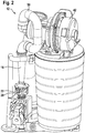
- Figure 2 shows a view of the fuel-air mixing device 10 in a heating device 12 according to the invention.
- a constriction 14 of a Venturi tube 16 there is a fuel opening 18 of a fuel nozzle 20 which is fastened by means of a connection holder 22.
- the connection holder 22 consists of an annular element which comprises the fuel nozzle 20 and of which four are arranged equidistantly Extend fingers that are connected to the Venturi tube 16.
- an air opening 24 is formed between the Venturi tube 16 and the fuel nozzle 20, through which air 26 present in the surroundings flows (represented by an arrow).
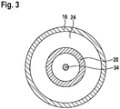
- Figure 3 shows that the air opening 24 is essentially annular.
- connection holder 22 can be changed, a smaller number of materials being saved and a better air supply being ensured. A larger number of fingers improves the mechanical stability of the connection holder 22. In particularly advantageous embodiments, the number of fingers is between three and twelve.
- the connection holder 22 is cylindrical and / or funnel-shaped, wherein the venturi 16 and the fuel nozzle 20 are each enclosed in the opposite ends of the connection holder 22 and the air supply is ensured through openings in the cylinder and / or funnel jacket.
- a fuel 28 (represented by arrows) is fed through a fuel feed line 30 into a fuel chamber 32.
- the fuel nozzle 20 and the fuel chamber 32 are made from one workpiece; in further variants, they are made from separate and firmly or detachably connected parts. In this way, the fuel nozzle 20 can be adapted to different Venturi tubes 16 with different geometries, the same workpiece being usable for the fuel chamber 32.
- the fuel 28 is introduced into the fuel chamber 32 via the fuel feed line 30.
- the fuel-air mixing device 10 in particular in a heater 12 according to the invention, which is explained in more detail below, there is a negative pressure on the side of the venturi tube 16 facing away from the fuel nozzle 20, so that the air 26 passes through the air opening 24 is sucked in and accelerated to the bottleneck 14.
- the fuel 28 is introduced into the constriction 14 via the fuel nozzle 20 and sucked in in the direction of flow.
- the fuel opening 18 precisely positioned by the connection holder 22 is in the position with the lowest negative pressure, so that the fuel 28 is sucked in at a high flow rate. This enables a high modulation of the burner output with a constant fuel-air ratio.
- the fuel nozzle 20 has a needle 34.
- the needle is located on the longitudinal axis of the fuel nozzle 20. It can be moved along this longitudinal axis.
- the needle 34 tapers towards the fuel opening 18.
- the opening cross section of the fuel opening 18 can be adjusted by moving the needle 34.
- the needle diameter decreases linearly with the length, the needle 34 always being arranged symmetrically about the longitudinal axis of the fuel nozzle 20. Therefore, in the exemplary embodiment, the opening cross section of the fuel opening 18 depends in a square manner on the immersion depth of the needle 34.
- the needle diameter changes non-linearly along the length of the needle 34.
- the amount of fuel 28 supplied can be set precisely depending on the immersion depth of the needle 26. This enables a very precise implementation of one adapted to the technical requirements Fuel dosing and in particular allows an increase in dosing accuracy without changing the shifting mechanism. This is particularly advantageous for the inexpensive manufacture and adaptation of different versions of the fuel-air mixing device 10 for use under different technical requirements, since only the profile of the needle 34 has to be changed here.
- the geometry of the needle 34, in particular the needle tip, is optimized with regard to its flow properties.
- the needle tip of the needle 34 has a peg-shaped adjusting body 38. In this way, a particularly laminar fuel influence in the air flow at the constriction 14 is ensured.
- Figure 4B illustrates an alternative geometry of an adjusting body 38.
- the radius of the adjusting body 38 initially widens linearly starting from the needle 34, from a turning point the radius of the adjusting body 38 decreases linearly.
- the needle 34 is guided from the direction opposite the fuel nozzle 20 to the fuel opening 18. This construction offers the advantage that an adjustment mechanism for the needle 34 can be arranged behind and / or in the Venturi tube 16 in the flow direction. This enables a more compact design of the fuel-air mixing device 10.
- the needle 34 is arranged at an angle to the axis of symmetry of the fuel nozzle 20 and / or decentrally. In this way, the fuel 28 becomes asymmetrical in the air flow let in, which increases the formation of turbulence and thus accelerates the mixing of air 26 and fuel 28.
- a similar effect is achieved in variants with a fuel nozzle 20 arranged decentrally relative to the axis of symmetry of the venturi 16.
- the position of the fuel nozzle 20 which is arranged centrally relative to the Venturi tube 16 is fixed by the connection holder 22.
- the position of the fuel nozzle 20 and thus the fuel opening 18 is designed to be adjustable.
- the degree of turbulence of the outflowing fuel 28 can be regulated with the immersion depth.
- the normal to the fuel opening 18 is arranged parallel to the axis of symmetry of the Venturi tube 16, so that the fuel is sucked in in the direction of the air flow.
- the normal to the fuel opening 18 has an angle between 0 ° and 45 ° relative to the axis of symmetry of the Venturi tube 16. In this way, the degree of turbulence and thus the mixing of the fuel-air mixture can be adjusted.
- FIGS Figures 5A and B Variants are shown in which the immersion depth of the fuel nozzle 20 can be adjusted via a thread 36. It is in the in Figure 5A The variant shown connects the Venturi tube 16 to the connection holder 22 via a thread 36. In the in Figure 5B illustrated variant, the connection holder 22 and the fuel nozzle 20 are connected via a thread 36. In an embodiment, not shown, with two threads 36, the variants from FIGS Figures 5A and B combined, the two threads are 36 each provided for the rough adjustment and the fine adjustment of the position of the fuel nozzle 20.
- the fuel nozzle 20 and / or the Venturi tube 16 are mounted displaceably relative to the connection holder and are or are fixed with a locking mechanism, such as a snap lock, a locking screw, a folding element or a magnetic lock.
- the axial positioning of the fuel nozzle 20 can be adjusted hydraulically or pneumatically with actuators such as electric motors, linear motors. These actuators are connected directly or indirectly, for example by means of a thread, to the fuel nozzle 20 and can also be used to actuate a locking mechanism. All actuators and manually operated adjustment mechanisms can be used in combination.
- the size and / or shape of the air opening 24 can be varied by changing the immersion depth of the fuel nozzle 20.
- the amount of air drawn in and / or the fuel-air ratio and / or the degree of turbulence of the air 26 and the fuel 28 can thus be influenced.
- the fuel nozzle 20, which can be variably positioned can be locked. In this way the setting of the fuel nozzle is protected against changes and manipulation.
- the locking device can be implemented, for example, in the form of a locking screw and / or a locking element and / or a folding element. In further embodiments, the locking device is designed to be closable, in particular sealable.
- the opening cross section of the fuel opening 18 is set by moving the needle 34 by means of an electric motor 40 (shown schematically in FIG Figure 1 ).
- the rotary movement of the electric motor 40 is converted into a longitudinal movement via a gear.
- the position of the needle is controlled directly with a linear motor and / or pneumatically and / or hydraulically.
- the needle can be adjusted manually, for example via a thread or by means of a freely movable bearing with a locking mechanism. This is advantageous in areas of application in which an adjustment of the fuel opening is rarely necessary. Variants in which the manually adjustable needle can be locked and the lock can be locked, in particular sealed, are particularly advantageous.
- the opening cross section of the fuel opening 18 is regulated via a needle 34 whose length can be changed. This enables a particularly compact design of the fuel-air mixing device 10.
- FIG. 6 schematically shows a heater 12 having a blower 42, a burner 44 and a fuel-air mixing device 10.
- the fuel 28 is fed to the fuel-air mixing device 10 via the fuel feed line 30.
- the fuel control valve 48 is constructed in such a way that it provides the fuel 28 to a predetermined, constant pressure regardless of its input pressure. It is particularly advantageous if the fuel 28 is regulated to a pressure that is equal to or substantially the same as the ambient pressure. In other variants, the fuel is set to a value proportional to the ambient pressure. In others The fuel pressure is varied according to the heating power currently required. This is particularly advantageous in the case of variants in which the blower 42 is operated at constant power, since the fuel flow and thus the burner power can be regulated with the aid of the fuel control valve 48.
- the fuel 28 is mixed with the inflowing air 26, sucked in by the blower 42 and fed to the burner 44 via a feed hood 50.
- the burner 44 is designed as a downdraft burner, below which a heat exchanger 52 is arranged, to which a flow line 54 and a return line 56 for heating water are connected.
- the exhaust gases are conducted to the outside through an exhaust gas line 58 from the heat exchanger 52 via an exhaust gas outlet 60.
- control system 62 which is connected via bus lines 64 to the fuel control valve 48, to the burner 44 and to the fuel-air mixing device 10 and has an external connection 66.
- the external connection 66 can be connected to an operating element which enables the setting and control of heater parameters and functions.
- further components of the heater 12 are connected to the control system 62, for example the blower 42 for regulating the speed and / or a radio module for communicating with external operating and control elements.
- control system 62 communicates wirelessly with the heater components, preferably over a radio link.
- FIG. 7 schematically represents the mode of operation of the heater 10 according to the invention.
- the blower 42 sucks over the heater according to the invention
- Fuel-air mixing device 10 applies a fuel-air mixture and conveys it via feed hood 50 to burner 44.
- fuel control valve 48 is attached directly to fuel chamber 32 of fuel-air mixing device 10, which acts as an angle piece is executed. This allows a particularly space-saving arrangement in the heater 12. In this way, a particularly compact design of the heater 12 is made possible.
- the fuel control valve 48 and the fuel line 46 are arranged parallel or substantially parallel to the fuel nozzle 20. This is advantageous for use in elongated heating devices 12 with a predetermined maximum diameter.
- the adjustment mechanism for the needle is located partially or completely within the fuel chamber 32 and / or the fuel feed line 30 and / or the fuel control valve 48 and / or the fuel line 46.
- the fuel-air mixture burns with a flame 68, which is monitored with an ionization electrode 70.
- the hot exhaust gases flow around the heat exchanger and are cooled by it.
- the ionization electrode 70 measures the ionization current and sends this value to the control system 62.
- the fuel-air ratio can be determined from the ionization current.
- the control system 62 regulates the fuel-air ratio via the immersion depth of the needle 34 in order to optimize the combustion, for example with regard to emissions and efficiency.
- sensors suitable for determining the fuel-air ratio are used instead of the ionization electrode, for example by measuring the residual oxygen (lambda probe), of the carbon dioxide or carbon monoxide content in the exhaust gases and of ultraviolet or infrared radiation in the flame 68. Any combination of all of the measurement methods listed for determining the fuel-air ratio is also used.
- the sensor or sensors is / are attached in / on the burner 44 and / or in / on the exhaust line 58 and / or in / on the exhaust outlet 60.
- the actuator that sets the immersion depth of the fuel nozzle 20 is connected to the control system via a bus line 64. In this way, the position of the fuel opening 18 in the constriction 14 can be adjusted automatically.
- the ionization current is measured in the first step by means of the ionization electrode 70 and transmitted to the control system 62. If the ionization current deviates from a predetermined, power-dependent value, the control system 62 changes the immersion depth of the needle 34 in a second step such that the ionization current largely assumes the predetermined value. In this way, the operation of the heater 12 can be ensured with an optimal fuel-air ratio.
- a sensor for determining the fuel-air ratio that does not measure an ionization current for example a sensor for determining the residual oxygen (lambda probe), the carbon dioxide or the carbon monoxide content in the exhaust gases, see above, is described in in the first step, the corresponding sensor measured value is determined by means of this sensor.
- This sensor measured value is used in the second step to set the immersion depth of the needle 34. If the sensor measured value deviates from a predetermined, performance-dependent value, the control system 62 changes the immersion depth of the needle 34 in a second step such that the sensor measured value largely assumes the predetermined value.
- the fuel system is determined in an intermediate step by the control system 62 with the aid of stored characteristic maps from the ionization current or the sensor measured value and the burner output. If the fuel-air ratio deviates from a predetermined value by at least a defined deviation, the immersion depth of the needle 34 is set in a second step such that the fuel-air ratio largely assumes the predetermined value.
- the ionization electrode 70 or the sensor in the first step transmits a plurality of ionization current measurements or sensor measurement values to the control system 62, which uses this to determine the rate of change of the ionization current or the sensor measurement variable or the fuel-air ratio.
- further measurement data are transmitted from further sensors to the control system 62 in the first step and taken into account for the adjustment of the adjustable needle 34.
- the burner output is set to a defined value before the first step. This is advantageous in systems and / or parameter areas where the burner output cannot be assigned to an optimal ionization current or sensor measurement value or where burner output and ionization current or sensor measured value cannot be clearly assigned to a fuel-air ratio.
- control system 62 adjusts the position of the fuel nozzle 20 in an intermediate step, which can be carried out before or after the third step.
Landscapes
- Engineering & Computer Science (AREA)
- Chemical & Material Sciences (AREA)
- Combustion & Propulsion (AREA)
- Mechanical Engineering (AREA)
- General Engineering & Computer Science (AREA)
- Regulation And Control Of Combustion (AREA)
Description
- Die Erfindung betrifft ein Heizgerät gemäß Anspruch 1. Die Erfindung betrifft auch ein Verfahren zur Regelung eines Heizgeräts mit einer solchen Brennstoff-Luft-Mischeinrichtung.
- Die
EP2863125A1 zeigt und beschreibt eine Brennstoff-Luft-Mischeinrichtung in der Form einer Venturi-Durchführung für einen Gebläse-unterstützten Brenner. - Die Luftansaugung erfolgt durch das Gebläse und aufgrund der Unterdruckverhältnisse im Bereich der Venturi-Engstelle wird der gasförmige Brennstoff automatisch eingesaugt. Das Brennstoff-Luft-Verhältnis wird über die Position der Öffnung für die Brennstoffzufuhr eingestellt. Heizgeräte mit einer solchen Anordnung sind in ihrer Möglichkeit, das Brennstoff-Luft-Verhältnis über einen weiten Modulationsbereich zu verändern, für heutige Wünsche zu stark begrenzt.
-
DE102013220954 offenbart ein Heizgerät gemäß dem Oberbegriff des Anspruchs 1. - Die erfindungsgemäße Brennstoff-Luft-Mischeinrichtung mit den Merkmalen des Hauptanspruchs hat den Vorteil, dass dadurch, dass die Nadel in der Brennstofföffnung verstellbar ist, die Regelung der der strömenden Luft zugeführten Brennstoffmenge durch das Verstellen der Nadel stattfinden kann. Dadurch muss die Position der Brennstofföffnung in der Engstelle nicht mehr verändert werden, um die Brennstoffmenge einzustellen und kann fixiert werden. Das ermöglicht es, den Brennstoffaustritt in dem Bereich mit dem tiefsten Saugdruck zu platzieren und den Brennstoff stets mit hoher Geschwindigkeit einzuleiten.
- Auf diese Weise kann das Brennstoff-Luft-Verhältnis durch die Nadel sehr präzise eingestellt werden ohne den großen Modulationsbereich des Luft-Flusses einzuschränken. Das ermöglicht eine schnelle und genaue Anpassung an äußere Randbedingungen, insbesondere an Schwankungen der Gasdichte und Gasqualität. So können unterschiedliche Brennstoffarten zugeführt werden und über die Einstellung der Brennstofföffnung mit der Nadel das jeweilige Mischungsverhältnis optimiert werden.
- Durch die in den Unteransprüchen aufgeführten Merkmale sind vorteilhafte Weiterbildungen des Heizgerätes nach dem Hauptanspruch möglich. So ist es von Vorteil, wenn die Position der Brennstofföffnung in der Engstelle einstellbar ist. So können altersbedingte Änderungen an den geometrischen oder strömungstechnischen Verhältnissen einfach korrigiert werden. Auch können auf diese Weise Fertigungstoleranzen ausgeglichen werden. Zusätzlich kann so der Luftdurchfluss reguliert werden, was insbesondere bei einem Einsatz der Brennstoff-Luft-Mischeinrichtung in einem Heizgerät mit einem Gebläse mit konstanter Drehzahl die Einstellung der Brennerleistung ermöglicht.
- Weiterhin ist es von Vorteil, wenn die einmal eingestellte Brennstofföffnung arretiert werden kann. Dies kann zum Beispiel direkt nach dem Einbau und der Kalibrierung der Brennstoff-Luft-Mischeinrichtung in einem Heizgerät im Werk erfolgen oder aber vor Ort, wenn das Heizgerät aufgestellt wird.
- Wird der Brennstoffaustritt mit der Nadel direkt über die Veränderung des Öffnungsquerschnitts der Brennstofföffnung eingestellt, so verbessern sich die Strömungsverhältnisse. Die Turbulenzen im Brennstoff-Fluss werden reduziert.
- Die Strömungsverhältnisse verbessern sich weiter, wenn die Brennstofföffnung so ausgeführt ist, dass der Brennstoff zentrisch in die Luftströmung eingeleitet wird. Auf diese Weise hat das Strömungsprofil eine besonders stabile Symmetrie, was den Brennstoff sauber entlang der strömenden Luft fließen lässt. So werden Turbulenzen und Verwirbelungen durch abreißende Strömungslinien vermieden und eine besonders druckverlustarme Strömung ermöglicht.
- Eine weitere Verbesserung tritt ein, wenn die Verstellung der Nadel automatisiert erfolgen kann. Dazu ist es vorteilhaft, die Nadel über einen Aktuator verstellen zu können. Ein besonders vorteilhafter Aktuator ist ein Elektromotor, dieser ermöglicht eine schnelle und präzise Ansteuerung und erlaubt eine kompakte, platzsparende Bauweise.
- Für ein Heizgerät mit solch einer Brennstoff-Luft-Mischeinrichtung ergeben sich darüber hinaus weitere Vorteile. Die Brennerleistung kann durch die Gebläseleistung eingestellt werden, ohne das Brennstoff-Luft-Verhältnis zu ändern. Das ermöglicht eine optimale und saubere Verbrennung über einen sehr großen Modulationsbereich. Das ist beispielsweise in gut gedämmten Häusern von Vorteil, da in solchen ein geringer Leistungswert für die Heizung, jedoch ein hoher Leistungswert für das Brauchwasser benötigt wird. Die Gewährleistung des optimalen Vermischungsverhältnisses ist dabei durch das Einstellen der Brennstofföffnung mit der Nadel möglich. Damit ist es nicht notwendig, die eingeführte Brennstoffmenge über den Brennstoffdruck einzustellen, etwa durch eine Drosselung der Brennstoffzufuhr vor der Brennstofföffnung, was den Modulationsbereich einschränken würde.
- Ein besonders großer Modulationsbereich wird erreicht, wenn der Brennstoff mit maximaler Einströmgeschwindigkeit in die Luftströmung eingeleitet wird. Das wird durch einen unter einem vorbestimmten, insbesondere konstanten Druck bereitstehenden Brennstoff ermöglicht, welcher durch ein Brennstoffregelventil bereitgestellt wird.
- Weist das Heizgerät einen Sensor zur Bestimmung eines Brennstoff-Luft-Verhältnisses auf, erlaubt die Kenntnis des Brennstoff-Luft-Verhältnisses Rückschlüsse auf die Qualität der Verbrennung. Diese Information hilft bei der Optimierung der Verbrennung.
- Eine weitere Verbesserung tritt ein, wenn das Heizgerät ein Steuersystem aufweist, welches die Nadel automatisch verstellt. So kann das Heizgerät mit einem durch eine automatische Steuerung sichergestellten optimalen Brennstoff-Luft-Verhältnis betrieben werden. Auf diese Weise wird der Bedienkomfort erhöht und das Auftreten von Einstellungsfehlern weitestgehend vermieden.
- Ein Verfahren zur Regelung des Heizgeräts, wobei ein Sensor mindestens einen Messwert bestimmt und das Steuersystem in Abhängigkeit vom Messwert die Nadel verstellt, erlaubt es, bei schnell veränderlichen inneren und äußeren Bedingungen eine stets optimale Verbrennung zu gewährleisten.
- In den Zeichnungen sind Ausführungsbeispiele der erfindungsgemäßen Brennstoff-Luft-Mischeinrichtung sowie des erfindungsgemäßen Brenners dargestellt und in der nachfolgenden Beschreibung näher erläutert. Es zeigen
-
Figur 1 einen Schnitt durch eine erfindungsgemäße Brennstoff-Luft-Mischeinrichtung, -
Figur 2 eine Darstellung der erfindungsgemäßen Brennstoff-Luft-Mischeinrichtung in einem erfindungsgemäßen Heizgerät, -
Figur 3 einen Schnitt nach Linie III-III inFigur 1 , -
Figuren 4A und B Varianten der Brennstoff-Luft-Mischeinrichtung, -
Figuren 5A und B Varianten nach der Einzelheit V inFigur 1 , -
Figur 6 eine schematische Darstellung des erfindungsgemäßen Heizgeräts und -
Figur 7 eine schematische Darstellung der Funktionsweise des erfindungsgemäßen Heizgeräts. - In
Figur 1 ist ein Schnitt durch eine erfindungsgemäße Brennstoff-Luft-Mischeinrichtung 10 dargestellt,Figur 2 zeigt eine Ansicht der Brennstoff-Luft-Mischeinrichtung 10 in einem erfindungsgemäßen Heizgerät 12. Im Bereich einer Engstelle 14 eines Venturirohrs 16 befindet sich eine Brennstofföffnung 18 einer Brennstoffdüse 20, welche mittels eines Verbindungshalters 22 befestigt ist. Im Ausführungsbeispiel besteht der Verbindungshalter 22 aus einem ringförmigen Element, welches die Brennstoffdüse 20 umfasst und von welchem vier äquidistant angeordnete Finger ausgehen, welche mit dem Venturirohr 16 verbunden sind. Auf diese Weise wird zwischen dem Venturirohr 16 und der Brennstoffdüse 20 eine Luftöffnung 24 ausgebildet, durch welche in der Umgebung vorhandene Luft 26 (dargestellt durch einen Pfeil) einströmt. -
Figur 3 zeigt, dass die Luftöffnung 24 im Wesentlichen ringförmig ausgebildet ist. - In anderen Varianten kann die Zahl der Finger des Verbindungshalters 22 verändert werden, wobei eine kleinere Zahl Material einspart sowie eine bessere Luftversorgung gewährleistet. Eine größere Zahl an Fingern verbessert die mechanische Stabilität des Verbindungshalters 22. In besonders vorteilhaften Ausführungen liegt die Zahl der Finger zwischen drei und zwölf. In weiteren Ausführungen ist der Verbindungshalter 22 zylinder- und/oder trichterförmig ausgeführt, wobei das Venturirohr 16 und die Brennstoffdüse 20 jeweils in den gegenüberliegenden Enden des Verbindungshalters 22 eingefasst sind und die Luftzufuhr durch Öffnungen im Zylinder- und/oder Trichtermantel gewährleistet wird.
- Ein Brennstoff 28 (dargestellt durch Pfeile) wird durch eine Brennstoffzuleitung 30 in eine Brennstoffkammer 32 geleitet. Im Ausführungsbeispiel sind die Brennstoffdüse 20 und die Brennstoffkammer 32 aus einem Werkstück gefertigt, in weiteren Varianten sind diese aus separaten und fest oder lösbar verbundenen Teilstücken gefertigt. Auf diese Weise ist die Brennstoffdüse 20 an verschiedene Venturirohre 16 mit unterschiedlichen Geometrien anpassbar wobei das gleiche Werkstück für die Brennstoffkammer 32 verwendbar ist.
- Der Brennstoff 28 wird über die Brennstoffzuleitung 30 in die Brennstoffkammer 32 eingeleitet. Im für die erfindungsgemäße Brennstoff-Luft-Mischeinrichtung 10 vorgesehenen Einsatzumfeld, insbesondere in einem erfindungsgemäßen Heizgerät 12, welches unten näher erläutert wird, befindet sich an der von der Brennstoffdüse 20 abgewandten Seite des Venturirohrs 16 ein Unterdruck, so dass die Luft 26 durch die Luftöffnung 24 eingesaugt und bis zur Engstelle 14 beschleunigt wird. Der Brennstoff 28 wird über die Brennstoffdüse 20 in die Engstelle 14 eingeführt und in Strömungsrichtung angesaugt. Die durch den Verbindungshalter 22 exakt positionierte Brennstofföffnung 18 befindet sich an der Position mit dem tiefsten Unterdruck, so dass der Brennstoff 28 mit hoher Strömungsgeschwindigkeit angesaugt wird. Das ermöglicht eine hohe Modulation der Brennerleistung bei konstantem Brennstoff-Luft-Verhältnis.
- Im Ausführungsbeispiel weist die Brennstoffdüse 20 eine Nadel 34 auf. Die Nadel befindet sich auf der Längsachse der Brennstoffdüse 20. Sie ist entlang dieser Längsachse verschiebbar. Die Nadel 34 verjüngt sich hin zur Brennstofföffnung 18. Dadurch ist durch das Verschieben der Nadel 34 der Öffnungsquerschnitt der Brennstofföffnung 18 einstellbar. Hier nimmt der Nadeldurchmesser linear mit der Länge ab, wobei die Nadel 34 stets symmetrisch um die Längsachse der Brennstoffdüse 20 angeordnet ist. Daher hängt im Ausführungsbeispiel der Öffnungsquerschnitt der Brennstofföffnung 18 quadratisch von der Eintauchtiefe der Nadel 34 ab.
- In alternativen Ausführungsformen ändert sich der Nadeldurchmesser nichtlinear entlang der Länge der Nadel 34. Auf diese Weise kann die zugeführte Menge an Brennstoff 28 in Abhängigkeit von der Eintauchtiefe der Nadel 26 exakt eingestellt werden. Das ermöglicht eine sehr präzise Umsetzung einer an die technischen Anforderungen angepassten Brennstoffdosierung und erlaubt insbesondere eine Erhöhung der Dosierungsgenauigkeit ohne den Verschiebungsmechanismus zu ändern. Das ist besonders für die günstige Fertigung und Anpassung von verschieden Ausführungen der Brennstoff-Luft-Mischeinrichtung 10 für den Einsatz unter jeweils unterschiedlichen technischen Anforderungen von Vorteil, da hier lediglich das Profil der Nadel 34 geändert werden muss.
- In weiteren Ausführungsformen ist die Geometrie der Nadel 34, insbesondere der Nadelspitze, hinsichtlich ihrer Strömungseigenschaften optimiert. In
Figur 4A weist die Nadelspitze der Nadel 34 einen zapfenförmigen Einstellkörper 38 auf. Auf diese Weise wird ein besonders laminarer Brennstoffeinfluss in die Luftströmung an der Engstelle 14 gewährleistet. -
Figur 4B illustriert eine alternative Geometrie eines Einstellkörpers 38. Hier weitet sich der Radius des Einstellkörpers 38 von der Nadel 34 ausgehend zunächst linear auf, ab einem Wendepunkt nimmt der Radius des Einstellkörpers 38 linear ab. Weiterhin wird in dieser Ausführungsform die Nadel 34 aus der der Brennstoffdüse 20 entgegengesetzten Richtung an die Brennstofföffnung 18 geführt. Diese Konstruktion bietet den Vorteil, dass ein Verstellmechanismus für die Nadel 34 in Strömungsrichtung hinter dem und/oder im Venturirohr 16 angeordnet werden kann. Dies ermöglicht eine kompaktere Bauform der Brennstoff-Luft-Mischeinrichtung 10. - In anderen Varianten ist die Nadel 34 in einem Winkel zur Symmetrieachse der Brennstoffdüse 20 und/oder dezentral angeordnet. Auf diese Weise wird der Brennstoff 28 asymmetrisch in die Luftströmung eingelassen, was die Bildung von Turbulenzen verstärkt und somit die Vermischung von Luft 26 und Brennstoff 28 beschleunigt.
- Ein ähnlicher Effekt wird in Varianten mit relativ zur Symmetrieachse des Venturirohrs 16 dezentral angeordneter Brennstoffdüse 20 erzielt. Im Ausführungsbeispiel ist die Position der relativ zum Venturirohr 16 zentral angeordneten Brennstoffdüse 20 durch den Verbindungshalter 22 fixiert. In anderen Varianten ist die Position der Brennstoffdüse 20 und damit der Brennstofföffnung 18 einstellbar ausgebildet. So kann in Varianten mit relativ zur Symmetrieachse des Venturirohrs 16 verschiebbarer und dezentral angeordneter Brennstoffdüse 20 mit der Eintauchtiefe der Turbulenzgrad des ausströmenden Brennstoffes 28 reguliert werden.
- Im Ausführungsbeispiel ist die Normale der Brennstofföffnung 18 parallel zur Symmetrieachse des Venturirohrs 16 angeordnet, so dass der Brennstoff in Richtung der Luftströmung eingesaugt wird. In anderen Varianten weist die Normale der Brennstofföffnung 18 einen Winkel zwischen 0° und 45° relativ zur Symmetrieachse des Venturirohrs 16 auf. Auf diese Weise kann der Turbulenzgrad und damit die Vermischung der Brennstoff-Luft-Mischung eingestellt werden.
- In den
Figuren 5A und B sind Varianten dargestellt, in welchen die Eintauchtiefe der Brennstoffdüse 20 über ein Gewinde 36 einstellbar ist. Dabei ist in der inFigur 5A gezeigten Variante das Venturirohr 16 über ein Gewinde 36 mit dem Verbindungshalter 22 verbunden. In der inFigur 5B dargestellten Variante werden der Verbindungshalter 22 und die Brennstoffdüse 20 über ein Gewinde 36 verbunden. In einer nicht gezeigten Ausführungsform mit zwei Gewinden 36 sind die Varianten aus denFiguren 5A und B kombiniert, dabei sind die beiden Gewinde 36 jeweils für die grobe Einstellung und die Feinjustierung der Position der Brennstoffdüse 20 vorgesehen. - In anderen, nicht dargestellten Varianten sind die Brennstoffdüse 20 und/oder das Venturirohr 16 relativ zum Verbindungshalter verschiebbar gelagert und werden oder wird mit einem Feststellmechanismus, etwa einem Rastverschluss, einer Feststellschraube, ein Klappelement oder einem Magnetverschluss, fixiert. Dabei kann die axiale Positionierung der Brennstoffdüse 20 mit Aktuatoren wie Elektromotoren, Linearmotoren, hydraulisch oder pneumatisch eingestellt werden. Diese Aktuatoren sind direkt oder indirekt, etwa durch ein Gewinde, mit der Brennstoffdüse 20 verbunden und können auch für die Betätigung eines Feststellmechanismus eingesetzt werden. Alle Aktuatoren und manuell betriebenen Verstellmechanismen sind in Kombination einsetzbar.
- Durch die Veränderung der Eintauchtiefe der Brennstoffdüse 20 kann die Größe und/oder Form der Luftöffnung 24 variiert werden. So kann die eingesaugte Menge der Luft und/oder das Brennstoff-Luft-Verhältnis und/oder der Turbulenzgrad der Luft 26 und des Brennstoffs 28 beeinflusst werden.
- In weiteren, nicht gezeigten Ausführungsformen ist die variabel positionierbar ausgestaltete Brennstoffdüse 20 arretierbar. Auf diese Weise wird die Einstellung der Brennstoffdüse vor Veränderungen und Manipulationen geschützt. Die Arretiereinrichtung kann beispielsweise in der Form einer Feststellschraube und/oder eines Rastelements und/oder eines Klappelements realisiert sein. In weiteren Ausführungen ist die Arretiereinrichtung verschließbar, insbesondere plombierbar, ausgeführt.
- Die Einstellung des Öffnungsquerschnitts der Brennstofföffnung 18 erfolgt im Ausführungsbeispiel durch das Verschieben der Nadel 34 mittels eines Elektromotors 40 (schematisch dargestellt in
Figur 1 ). Dabei wird die Drehbewegung des Elektromotors 40 über ein Getriebe in eine Längsbewegung überführt. In anderen Varianten wird die Position der Nadel direkt mit einem Linearmotor und/oder pneumatisch und/oder hydraulisch geregelt. In anderen Ausführungen ist die Nadel manuell einstellbar, etwa über ein Gewinde oder durch eine frei verschiebbare Lagerung mit einem Feststellmechanismus. Das ist in Einsatzbereichen von Vorteil, in welchen eine Anpassung der Brennstofföffnung nur selten nötig ist. Besonders vorteilhaft sind dann solche Varianten, in denen die manuell einstellbare Nadel arretierbar ist und die Arretierung verschließbar, insbesondere plombierbar ausgestaltet ist. - In anderen Varianten erfolgt die Regelung des Öffnungsquerschnitts der Brennstofföffnung 18 über eine in ihrer Länge veränderbaren Nadel 34. Dies ermöglicht eine besonders kompakte Bauform der Brennstoff-Luft-Mischeinrichtung 10.
-
Figur 6 zeigt schematisch ein Heizgerät 12, das ein Gebläse 42, einen Brenner 44 und eine Brennstoff-Luft-Mischeinrichtung 10 aufweist. Über eine Brennstoffleitung 46 und ein Brennstoffregelventil 48 wird der Brennstoff 28 über die Brennstoffzuleitung 30 der Brennstoff-Luft-Mischeinrichtung 10 zugeführt. Das Brennstoffregelventil 48 ist im Ausführungsbeispiel so aufgebaut, dass es den Brennstoff 28 unabhängig von seinem Eingangsdruck auf einen vorbestimmten, konstanten Druck bereitstellt. Besonders vorteilhaft ist es, wenn der Brennstoff 28 auf einem dem Umgebungsdruck gleichenden oder im Wesentlichen gleichenden Druck geregelt wird. In anderen Varianten wird der Brennstoff auf einen zum Umgebungsdruck proportionalen Wert eingestellt. In weiteren Varianten wird der Brennstoffdruck variiert, passend zur aktuell benötigten Heizleistung. Das ist besonders bei Varianten, in denen das Gebläse 42 mit konstanter Leistung betrieben wird, von Vorteil, da so mit Hilfe des Brennstoffregelventils 48 der Brennstoff-Fluss und somit die Brennerleistung geregelt werden kann. - In der Brennstoff-Luft-Mischeinrichtung 10 wird der Brennstoff 28 mit der einströmenden Luft 26 vermischt, von Gebläse 42 angesaugt und über eine Zuführhaube 50 dem Brenner 44 zugeführt. Im Ausführungsbeispiel ist der Brenner 44 als Fallstrom-Brenner ausgeführt, unterhalb dessen ein Wärmetauscher 52 angeordnet ist, an dem eine Vorlaufleitung 54 und eine Rücklaufleitung 56 für Heizwasser angeschlossen ist. Die Abgase werden durch eine Abgasleitung 58 von dem Wärmetauscher 52 über einen Abgasauslass 60 nach außen geleitet.
- Weiterhin ist im Heizgerät 12 ein Steuersystem 62 welches über Busleitungen 64 mit dem Brennstoffregelventil 48, mit dem Brenner 44 und mit der Brennstoff-Luft-Mischeinrichtung 10 verbunden ist sowie eine Außenverbindung 66 aufweist. Die Außenverbindung 66 ist an ein Bedienelement anschließbar, welches eine Einstellung und Steuerung von Heizgeräteparametern und -funktionen ermöglicht. In anderen Varianten sind weitere Komponenten des Heizgeräts 12 an das Steuersystem 62 angeschlossen, etwa das Gebläse 42 zur Regelung der Drehzahl und/oder ein Funkmodul zur Kommunikation mit externen Bedien- und Steuerelementen. In anderen Ausführungsformen kommuniziert das Steuersystem 62 drahtlos mit den Heizgerätkomponenten, bevorzugt über eine Funkverbindung.
-
Figur 7 stellt schematisch die Funktionsweise des erfindungsgemäßen Heizgeräts 10 dar. Das Gebläse 42 saugt über die erfindungsgemäße Brennstoff-Luft-Mischeinrichtung 10 ein Brennstoff-Luft-Gemisch an und fördert es über die Zuführhaube 50 zum Brenner 44. In der hier gezeigten Ausführung ist das Brennstoffregelventil 48 direkt an der Brennstoffkammer 32 der Brennstoff-Luft-Mischeinrichtung 10 angebracht, welche als Winkelstück ausgeführt ist. Dies erlaubt eine besonders platzsparende Anordnung im Heizgerät 12. Auf diese Weise wird eine besonders kompakte Bauform des Heizgeräts 12 ermöglicht. - In anderen Varianten ist das Brennstoffregelventil 48 und die Brennstoffleitung 46 parallel oder im Wesentlichen parallel zur Brennstoffdüse 20 angeordnet. Das ist für den Einsatz in langgestreckten Heizgeräten 12 mit einem vorgegebenen maximalen Durchmesser von Vorteil. In diesen Varianten befindet sich der Verstellmechanismus für die Nadel teilweise oder vollständig innerhalb der Brennstoffkammer 32 und/oder der Brennstoffzuleitung 30 und/oder von dem Brennstoffregelventil 48 und/oder der Brennstoffleitung 46.
- An der Unterseite des Brenners 44 verbrennt das Brennstoff-Luft-Gemisch mit einer Flamme 68, welche mit einer lonisationselektrode 70 überwacht wird. Die heißen Abgase umströmen den Wärmetauscher und werden von diesem abgekühlt. Die lonisationselektrode 70 misst den lonisationsstrom und sendet diesen Wert an das Steuersystem 62. Aus dem lonisationsstrom ist das Brennstoff-Luft-Verhältnis bestimmbar. Abhängig von lonisationsstrom regelt das Steuersystem 62 über die Eintauchtiefe der Nadel 34 das Brennstoff-Luft-Verhältnis um die Verbrennung zu optimieren, etwa bezüglich Emissionen und Wirkungsgrad.
- In anderen Varianten werden an Stelle der lonisationselektrode andere für die Ermittlung des Brennstoff-Luft-Verhältnisses geeignete Sensoren eingesetzt, zum Beispiel durch die Messung des Restsauerstoff-(Lambdasonde), des Kohlendioxid- oder des Kohlenmonoxidgehalts in den Abgasen sowie von Ultraviolett- oder Infrarotstrahlung in der Flamme 68. Auch die beliebige Kombination aller aufgeführten Messverfahren zur Bestimmung des Brennstoff-Luft-Verhältnisses wird verwendet. Dazu ist bzw. sind der Sensor bzw. die Sensoren im/am Brenner 44 und/oder in/an der Abgasleitung 58 und/oder in/an dem Abgasauslass 60 angebracht.
- Andere Ausführungsformen weisen weitere Sensoren auf, etwa Temperaturfühler und/oder Vibrationssensoren und/oder Spektrometer, welche weitere Verbrennungsparameter an das Steuersystem 62 melden und eine weitergehende Überwachung des Verbrennungsprozesses erlauben. In weiteren Varianten ist der die Eintauchtiefe der Brennstoffdüse 20 einstellende Aktuator über eine Busleitung 64 mit dem Steuersystem verbunden. Auf diese Weise kann die Position der Brennstofföffnung 18 in der Engstelle 14 automatisiert justiert werden.
- In einem Verfahren zur Regelung eines erfindungsgemäßen Heizgeräts 12 wird im Ausführungsbeispiel im ersten Schritt mittels der lonisationselektrode 70 der lonisationsstrom gemessen und an das Steuersystem 62 übermittelt. Weicht der lonisationsstrom von einem vorbestimmten, leistungsabhängigen Wert ab, ändert das Steuersystem 62 in einem zweiten Schritt die Eintauchtiefe der Nadel 34 so, dass der lonisationsstrom weitgehend den vorbestimmten Wert annimmt. Auf diese Weise kann der Betrieb des Heizgeräts 12 mit einem optimalen Brennstoff-Luft-Verhältnis sichergestellt werden.
- In Varianten mit einem Sensor zur Ermittlung des Brennstoff-Luft-Verhältnisses, der keinen lonisationsstrom misst, beispielweise ein Sensor zur Bestimmung des Restsauerstoff- (Lambdasonde), des Kohlendioxid- oder des Kohlenmonoxidgehalts in den Abgasen, siehe oben, wird im ersten Schritt mittels dieses Sensors der entsprechende Sensormesswert ermittelt. Dieser Sensormesswert wird im zweiten Schritt zur Einstellung der Eintauchtiefe der Nadel 34 verwendet. Weicht der Sensormesswert von einem vorbestimmten, leistungsabhängigen Wert ab, ändert das Steuersystem 62 im zweiten Schritt die Eintauchtiefe der Nadel 34 so, dass der Sensormesswert weitgehend den vorbestimmten Wert annimmt.
- In einem alternativen Verfahren wird in einem Zwischenschritt durch das Steuersystem 62 mit Hilfe von abgespeicherten Kennfeldern aus dem lonisationsstrom bzw. dem Sensormesswert und der Brennerleistung das Brennstoff-Luft-Verhältnis bestimmt. Weicht das Brennstoff-Luft-Verhältnis von einem vorbestimmten Wert mindestens mit einer definierten Abweichung ab, wird in zweiten Schritt die Eintauchtiefe der Nadel 34 so eingestellt, dass das Brennstoff-Luft-Verhältnis weitgehend den vorbestimmten Wert annimmt.
- In alternativen Varianten übermittelt die lonisationselektrode 70 bzw. der Sensor im ersten Schritt mehrere lonisationsstrommessungen bzw. Sensormesswerte an das Steuersystem 62 welches daraus die Änderungsgeschwindigkeit des lonisationsstromes bzw. der Sensormessgröße bzw. des Brennstoff-Luft-Verhältnisses ermittelt. In anderen Ausführungsvarianten werden im ersten Schritt weitere Messdaten von weiteren Sensoren an das Steuersystem 62 übermittelt und für das Justieren der verstellbaren Nadel 34 berücksichtigt.
- In alternativen Verfahren wird vor dem ersten Schritt die Brennerleistung auf einen definierten Wert eingestellt. Das ist in Systemen und/oder Parameterbereichen von Vorteil, wo sich die Brennerleistung nicht einem optimalen lonisationsstrom bzw. Sensormesswert zuordnen lässt bzw. wo sich Brennerleistung und lonisationsstrom bzw. Sensormesswert nicht eindeutig einem Brennstoff-Luft-Verhältnis zuordnen lassen.
- In weiteren Varianten stellt das Steuersystem 62 in einem Zwischenschritt, der vor oder nach dem dritten Schritt ausgeführt werden kann, die Position der Brennstoffdüse 20 ein.
Claims (10)
- Heizgerät (12) mit einem von einem Gebläse (42) unterstützten Brenner (44), einer Brennstoff-Luft-Mischeinrichtung (10), die über eine Brennstoffzuleitung (30) strömender Luft (26) insbesondere gasförmigen Brennstoff (28) zuführt und wobei die Brennstoff-Luft-Mischeinrichtung (10) eine Luftöffnung (24), eine Engstelle (14) sowie mindestens eine Brennstofföffnung (18) im Bereich der Engstelle (14) zum Zuführen von insbesondere gasförmigen Brennstoff (28) aufweist, dadurch gekennzeichnet, dass die Brennstofföffnung (18) eine verstellbare Nadel (34) aufweist und dass durch die Nadel (34) der Öffnungsquerschnitt der Brennstofföffnung (18) einstellbar ist.
- Heizgerät (12) nach Anspruch 1, dadurch gekennzeichnet, dass die Position der Brennstofföffnung (18) in der Engstelle (14) einstellbar ist.
- Heizgerät (12) nach Anspruch 2, dadurch gekennzeichnet, dass die Position der Brennstofföffnung (18) in der Engstelle (14) arretierbar ist.
- Heizgerät (12) nach einem der vorhergehenden Ansprüche, dadurch gekennzeichnet, dass die Brennstofföffnung (18) so ausgestaltet ist, dass der Brennstoff (28) zentrisch in die Luftströmung eingeleitet wird.
- Heizgerät (12) nach einem der vorhergehenden Ansprüche, dadurch gekennzeichnet, dass die Nadel (34) über einen Aktuator verstellbar ist.
- Heizgerät (12) nach einem der vorhergehenden Ansprüche, dadurch gekennzeichnet, dass die Nadel (34) über einen Elektromotor (40) verstellbar ist.
- Heizgerät (12) nach einem der vorhergehenden Ansprüche, dadurch gekennzeichnet, dass ein Brennstoffregelventil (48) den Brennstoff (28) auf einem vorbestimmbaren, insbesondere konstanten, Druck bereitstellt.
- Heizgerät (12) nach einem der vorhergehenden Ansprüche, dadurch gekennzeichnet, dass das Heizgerät (12) mindestens einen Sensor zur Bestimmung eines Brennstoff-Luft-Verhältnisses aufweist.
- Heizgerät (12) nach einem der vorhergehenden Ansprüche, dadurch gekennzeichnet, dass ein Steuersystem (62) die Nadel (34) automatisch verstellt.
- Verfahren zur Regelung eines Heizgeräts (12) nach Anspruch 9 in Verbindung mit Anspruch 8, dadurch gekennzeichnet, dass mindestens ein Sensor mindestens einen Messwert bestimmt und das Steuersystem (62) in Abhängigkeit vom Messwert die Nadel (34) verstellt.
Applications Claiming Priority (1)
| Application Number | Priority Date | Filing Date | Title |
|---|---|---|---|
| DE102016201624.5A DE102016201624A1 (de) | 2016-02-03 | 2016-02-03 | Brennstoff-Luft-Mischeinrichtung für ein Heizgerät |
Publications (2)
| Publication Number | Publication Date |
|---|---|
| EP3203151A1 EP3203151A1 (de) | 2017-08-09 |
| EP3203151B1 true EP3203151B1 (de) | 2020-02-12 |
Family
ID=57460409
Family Applications (1)
| Application Number | Title | Priority Date | Filing Date |
|---|---|---|---|
| EP16201672.9A Active EP3203151B1 (de) | 2016-02-03 | 2016-12-01 | Brennstoff-luft-mischeinrichtung für ein heizgerät |
Country Status (2)
| Country | Link |
|---|---|
| EP (1) | EP3203151B1 (de) |
| DE (1) | DE102016201624A1 (de) |
Families Citing this family (3)
| Publication number | Priority date | Publication date | Assignee | Title |
|---|---|---|---|---|
| DE102017217248A1 (de) | 2017-09-27 | 2019-03-28 | Robert Bosch Gmbh | Brennstoff-Luft-Mischeinrichtung und ein Heizgerät |
| DE102019217419A1 (de) * | 2019-11-12 | 2021-05-12 | Robert Bosch Gmbh | Mischeinrichtung für ein gebläsebetriebenes Heizgerät |
| DE102021123513A1 (de) * | 2021-09-10 | 2023-03-16 | Man Energy Solutions Se | Brenner und Verfahren zu dessen Herstellung |
Family Cites Families (7)
| Publication number | Priority date | Publication date | Assignee | Title |
|---|---|---|---|---|
| DE596838C (de) * | 1931-10-08 | 1934-05-11 | Karl Molnar Dipl Ing | Zerstaeuber fuer fluessige Brennstoffe, insbesondere fuer OElfeuerungen |
| AT259811B (de) * | 1966-07-08 | 1968-02-12 | Pierre Nibelle | Gasbrenner |
| DE3316190A1 (de) * | 1983-05-04 | 1984-11-15 | Hans Georg Dipl.-Ing. Zimmermann (FH), 7100 Heilbronn | Oel-blaubrenner |
| EP0754914B1 (de) * | 1995-07-19 | 2001-04-18 | Centre D'etude Et De Realisations D'equipement Et De Materiel (C.E.R.E.M.) S.A.R.L. | Einspritzvorrichtung für atmosphärische Gasbrenner von Heizgeräten, insbesondere des Infrarottyps |
| DE10324706B3 (de) * | 2003-05-30 | 2004-12-02 | Hovalwerk Ag | Vorrichtung zum Regeln des Gas/Luft-Verhältnisses für eine vormischende Verbrennungseinrichtung |
| DE102013220950A1 (de) | 2013-10-16 | 2015-04-16 | Robert Bosch Gmbh | Heizgerät mit einem von einem Gebläse unterstützten Brenner |
| DE102013220954A1 (de) * | 2013-10-16 | 2015-04-16 | Robert Bosch Gmbh | Heizgerät mit einem von einem Gebläse unterstützten Brenner |
-
2016
- 2016-02-03 DE DE102016201624.5A patent/DE102016201624A1/de active Pending
- 2016-12-01 EP EP16201672.9A patent/EP3203151B1/de active Active
Non-Patent Citations (1)
| Title |
|---|
| None * |
Also Published As
| Publication number | Publication date |
|---|---|
| EP3203151A1 (de) | 2017-08-09 |
| DE102016201624A1 (de) | 2017-08-03 |
Similar Documents
| Publication | Publication Date | Title |
|---|---|---|
| EP2594848B1 (de) | Verfahren zur Steuerung einer Feuerungseinrichtung und Feuerungseinrichtung | |
| DE2832708C2 (de) | ||
| WO2002077528A1 (de) | Verfahren und vorrichtung zur einstellung der luftzahl | |
| EP3683500B1 (de) | Verfahren zur regelung eines gasgemisches unter nutzung eines gassensors und eines gasgemischsensors | |
| DE19724861C1 (de) | Gasbrenner für einen Heizkessel | |
| EP3203151A1 (de) | Brennstoff-luft-mischeinrichtung für ein heizgerät | |
| DE202013105011U1 (de) | Shutter mit Anschlag | |
| DE3850935T2 (de) | Gas/luft-verhältnis-kontrollventil für gasbrenner. | |
| EP3499124A1 (de) | Heizgerätkomponente und verfahren zur einstellung eines brennstoffvolumenstroms | |
| DE112016000601T5 (de) | Vergaser-Brennstoffsteuerung | |
| DE3611909C3 (de) | Vorrichtung zur Steuerung der Menge und/oder des Mischungsverhältnisses eines Brenngas-Luft-Gemisches | |
| EP2928968B1 (de) | Russgenerator | |
| EP3870899B1 (de) | Verfahren zur überprüfung eines gasgemischsensors und ionisationssensors bei einem brenngasbetriebenen heizgerät | |
| EP2821700B1 (de) | Lanze für Verbrennung oder Abfackelung von brennbaren Abgasen | |
| DE102013220954A1 (de) | Heizgerät mit einem von einem Gebläse unterstützten Brenner | |
| EP2623863B1 (de) | Brenngas-Luft-Mischvorrichtung | |
| EP2863120B1 (de) | Brennstoff-Luft-Mischeinrichtung | |
| DE10348324B3 (de) | Verfahren zur Modulation der Heizleistung eines Brenners und Mischeinrichtung für einen Brenner | |
| EP3734159A1 (de) | Verfahren zur überprüfung eines gasgemischsensors bei einem brenngasbetriebenen heizgerät | |
| EP3460330A1 (de) | Mischeinrichtung für heizgeräte sowie heizgeräte mit einer solchen mischeinrichtung | |
| DE102011002324A1 (de) | Regeleinrichtung für einen Brenner und Verfahren zum Betrieb eines Brenners | |
| EP2925995B1 (de) | Brenngaszumischvorrichtung für eine gasbetriebene brennkraftmaschine | |
| DE10114901A1 (de) | Verfahren und Vorrichtung zur Einstellung der Luftzahl | |
| DE102004063992B4 (de) | Verfahren zur Steuerung einer Feuerungseinrichtung und Feuerungseinrichtung | |
| DE102011103612B4 (de) | Brenngaszumischvorrichtung für eine gasbetriebene Brennkraftmaschine |
Legal Events
| Date | Code | Title | Description |
|---|---|---|---|
| PUAI | Public reference made under article 153(3) epc to a published international application that has entered the european phase |
Free format text: ORIGINAL CODE: 0009012 |
|
| STAA | Information on the status of an ep patent application or granted ep patent |
Free format text: STATUS: THE APPLICATION HAS BEEN PUBLISHED |
|
| AK | Designated contracting states |
Kind code of ref document: A1 Designated state(s): AL AT BE BG CH CY CZ DE DK EE ES FI FR GB GR HR HU IE IS IT LI LT LU LV MC MK MT NL NO PL PT RO RS SE SI SK SM TR |
|
| AX | Request for extension of the european patent |
Extension state: BA ME |
|
| STAA | Information on the status of an ep patent application or granted ep patent |
Free format text: STATUS: REQUEST FOR EXAMINATION WAS MADE |
|
| 17P | Request for examination filed |
Effective date: 20180209 |
|
| RBV | Designated contracting states (corrected) |
Designated state(s): AL AT BE BG CH CY CZ DE DK EE ES FI FR GB GR HR HU IE IS IT LI LT LU LV MC MK MT NL NO PL PT RO RS SE SI SK SM TR |
|
| STAA | Information on the status of an ep patent application or granted ep patent |
Free format text: STATUS: EXAMINATION IS IN PROGRESS |
|
| 17Q | First examination report despatched |
Effective date: 20180925 |
|
| GRAP | Despatch of communication of intention to grant a patent |
Free format text: ORIGINAL CODE: EPIDOSNIGR1 |
|
| STAA | Information on the status of an ep patent application or granted ep patent |
Free format text: STATUS: GRANT OF PATENT IS INTENDED |
|
| INTG | Intention to grant announced |
Effective date: 20191001 |
|
| GRAS | Grant fee paid |
Free format text: ORIGINAL CODE: EPIDOSNIGR3 |
|
| GRAA | (expected) grant |
Free format text: ORIGINAL CODE: 0009210 |
|
| STAA | Information on the status of an ep patent application or granted ep patent |
Free format text: STATUS: THE PATENT HAS BEEN GRANTED |
|
| AK | Designated contracting states |
Kind code of ref document: B1 Designated state(s): AL AT BE BG CH CY CZ DE DK EE ES FI FR GB GR HR HU IE IS IT LI LT LU LV MC MK MT NL NO PL PT RO RS SE SI SK SM TR |
|
| REG | Reference to a national code |
Ref country code: GB Ref legal event code: FG4D Free format text: NOT ENGLISH |
|
| REG | Reference to a national code |
Ref country code: CH Ref legal event code: EP |
|
| REG | Reference to a national code |
Ref country code: AT Ref legal event code: REF Ref document number: 1232596 Country of ref document: AT Kind code of ref document: T Effective date: 20200215 |
|
| REG | Reference to a national code |
Ref country code: IE Ref legal event code: FG4D Free format text: LANGUAGE OF EP DOCUMENT: GERMAN |
|
| REG | Reference to a national code |
Ref country code: DE Ref legal event code: R096 Ref document number: 502016008690 Country of ref document: DE |
|
| REG | Reference to a national code |
Ref country code: NL Ref legal event code: FP |
|
| RAP2 | Party data changed (patent owner data changed or rights of a patent transferred) |
Owner name: ROBERT BOSCH GMBH |
|
| PG25 | Lapsed in a contracting state [announced via postgrant information from national office to epo] |
Ref country code: FI Free format text: LAPSE BECAUSE OF FAILURE TO SUBMIT A TRANSLATION OF THE DESCRIPTION OR TO PAY THE FEE WITHIN THE PRESCRIBED TIME-LIMIT Effective date: 20200212 Ref country code: NO Free format text: LAPSE BECAUSE OF FAILURE TO SUBMIT A TRANSLATION OF THE DESCRIPTION OR TO PAY THE FEE WITHIN THE PRESCRIBED TIME-LIMIT Effective date: 20200512 Ref country code: RS Free format text: LAPSE BECAUSE OF FAILURE TO SUBMIT A TRANSLATION OF THE DESCRIPTION OR TO PAY THE FEE WITHIN THE PRESCRIBED TIME-LIMIT Effective date: 20200212 |
|
| REG | Reference to a national code |
Ref country code: LT Ref legal event code: MG4D |
|
| PG25 | Lapsed in a contracting state [announced via postgrant information from national office to epo] |
Ref country code: BG Free format text: LAPSE BECAUSE OF FAILURE TO SUBMIT A TRANSLATION OF THE DESCRIPTION OR TO PAY THE FEE WITHIN THE PRESCRIBED TIME-LIMIT Effective date: 20200512 Ref country code: GR Free format text: LAPSE BECAUSE OF FAILURE TO SUBMIT A TRANSLATION OF THE DESCRIPTION OR TO PAY THE FEE WITHIN THE PRESCRIBED TIME-LIMIT Effective date: 20200513 Ref country code: SE Free format text: LAPSE BECAUSE OF FAILURE TO SUBMIT A TRANSLATION OF THE DESCRIPTION OR TO PAY THE FEE WITHIN THE PRESCRIBED TIME-LIMIT Effective date: 20200212 Ref country code: LV Free format text: LAPSE BECAUSE OF FAILURE TO SUBMIT A TRANSLATION OF THE DESCRIPTION OR TO PAY THE FEE WITHIN THE PRESCRIBED TIME-LIMIT Effective date: 20200212 Ref country code: IS Free format text: LAPSE BECAUSE OF FAILURE TO SUBMIT A TRANSLATION OF THE DESCRIPTION OR TO PAY THE FEE WITHIN THE PRESCRIBED TIME-LIMIT Effective date: 20200612 Ref country code: HR Free format text: LAPSE BECAUSE OF FAILURE TO SUBMIT A TRANSLATION OF THE DESCRIPTION OR TO PAY THE FEE WITHIN THE PRESCRIBED TIME-LIMIT Effective date: 20200212 |
|
| PG25 | Lapsed in a contracting state [announced via postgrant information from national office to epo] |
Ref country code: DK Free format text: LAPSE BECAUSE OF FAILURE TO SUBMIT A TRANSLATION OF THE DESCRIPTION OR TO PAY THE FEE WITHIN THE PRESCRIBED TIME-LIMIT Effective date: 20200212 Ref country code: PT Free format text: LAPSE BECAUSE OF FAILURE TO SUBMIT A TRANSLATION OF THE DESCRIPTION OR TO PAY THE FEE WITHIN THE PRESCRIBED TIME-LIMIT Effective date: 20200705 Ref country code: ES Free format text: LAPSE BECAUSE OF FAILURE TO SUBMIT A TRANSLATION OF THE DESCRIPTION OR TO PAY THE FEE WITHIN THE PRESCRIBED TIME-LIMIT Effective date: 20200212 Ref country code: LT Free format text: LAPSE BECAUSE OF FAILURE TO SUBMIT A TRANSLATION OF THE DESCRIPTION OR TO PAY THE FEE WITHIN THE PRESCRIBED TIME-LIMIT Effective date: 20200212 Ref country code: CZ Free format text: LAPSE BECAUSE OF FAILURE TO SUBMIT A TRANSLATION OF THE DESCRIPTION OR TO PAY THE FEE WITHIN THE PRESCRIBED TIME-LIMIT Effective date: 20200212 Ref country code: RO Free format text: LAPSE BECAUSE OF FAILURE TO SUBMIT A TRANSLATION OF THE DESCRIPTION OR TO PAY THE FEE WITHIN THE PRESCRIBED TIME-LIMIT Effective date: 20200212 Ref country code: SK Free format text: LAPSE BECAUSE OF FAILURE TO SUBMIT A TRANSLATION OF THE DESCRIPTION OR TO PAY THE FEE WITHIN THE PRESCRIBED TIME-LIMIT Effective date: 20200212 Ref country code: EE Free format text: LAPSE BECAUSE OF FAILURE TO SUBMIT A TRANSLATION OF THE DESCRIPTION OR TO PAY THE FEE WITHIN THE PRESCRIBED TIME-LIMIT Effective date: 20200212 Ref country code: SM Free format text: LAPSE BECAUSE OF FAILURE TO SUBMIT A TRANSLATION OF THE DESCRIPTION OR TO PAY THE FEE WITHIN THE PRESCRIBED TIME-LIMIT Effective date: 20200212 |
|
| REG | Reference to a national code |
Ref country code: DE Ref legal event code: R097 Ref document number: 502016008690 Country of ref document: DE |
|
| PLBE | No opposition filed within time limit |
Free format text: ORIGINAL CODE: 0009261 |
|
| STAA | Information on the status of an ep patent application or granted ep patent |
Free format text: STATUS: NO OPPOSITION FILED WITHIN TIME LIMIT |
|
| 26N | No opposition filed |
Effective date: 20201113 |
|
| PG25 | Lapsed in a contracting state [announced via postgrant information from national office to epo] |
Ref country code: PL Free format text: LAPSE BECAUSE OF FAILURE TO SUBMIT A TRANSLATION OF THE DESCRIPTION OR TO PAY THE FEE WITHIN THE PRESCRIBED TIME-LIMIT Effective date: 20200212 Ref country code: SI Free format text: LAPSE BECAUSE OF FAILURE TO SUBMIT A TRANSLATION OF THE DESCRIPTION OR TO PAY THE FEE WITHIN THE PRESCRIBED TIME-LIMIT Effective date: 20200212 |
|
| REG | Reference to a national code |
Ref country code: CH Ref legal event code: PL |
|
| PG25 | Lapsed in a contracting state [announced via postgrant information from national office to epo] |
Ref country code: MC Free format text: LAPSE BECAUSE OF FAILURE TO SUBMIT A TRANSLATION OF THE DESCRIPTION OR TO PAY THE FEE WITHIN THE PRESCRIBED TIME-LIMIT Effective date: 20200212 |
|
| REG | Reference to a national code |
Ref country code: BE Ref legal event code: MM Effective date: 20201231 |
|
| PG25 | Lapsed in a contracting state [announced via postgrant information from national office to epo] |
Ref country code: IE Free format text: LAPSE BECAUSE OF NON-PAYMENT OF DUE FEES Effective date: 20201201 Ref country code: LU Free format text: LAPSE BECAUSE OF NON-PAYMENT OF DUE FEES Effective date: 20201201 |
|
| PG25 | Lapsed in a contracting state [announced via postgrant information from national office to epo] |
Ref country code: LI Free format text: LAPSE BECAUSE OF NON-PAYMENT OF DUE FEES Effective date: 20201231 Ref country code: CH Free format text: LAPSE BECAUSE OF NON-PAYMENT OF DUE FEES Effective date: 20201231 |
|
| PG25 | Lapsed in a contracting state [announced via postgrant information from national office to epo] |
Ref country code: TR Free format text: LAPSE BECAUSE OF FAILURE TO SUBMIT A TRANSLATION OF THE DESCRIPTION OR TO PAY THE FEE WITHIN THE PRESCRIBED TIME-LIMIT Effective date: 20200212 Ref country code: MT Free format text: LAPSE BECAUSE OF FAILURE TO SUBMIT A TRANSLATION OF THE DESCRIPTION OR TO PAY THE FEE WITHIN THE PRESCRIBED TIME-LIMIT Effective date: 20200212 Ref country code: CY Free format text: LAPSE BECAUSE OF FAILURE TO SUBMIT A TRANSLATION OF THE DESCRIPTION OR TO PAY THE FEE WITHIN THE PRESCRIBED TIME-LIMIT Effective date: 20200212 |
|
| PG25 | Lapsed in a contracting state [announced via postgrant information from national office to epo] |
Ref country code: MK Free format text: LAPSE BECAUSE OF FAILURE TO SUBMIT A TRANSLATION OF THE DESCRIPTION OR TO PAY THE FEE WITHIN THE PRESCRIBED TIME-LIMIT Effective date: 20200212 Ref country code: AL Free format text: LAPSE BECAUSE OF FAILURE TO SUBMIT A TRANSLATION OF THE DESCRIPTION OR TO PAY THE FEE WITHIN THE PRESCRIBED TIME-LIMIT Effective date: 20200212 |
|
| PG25 | Lapsed in a contracting state [announced via postgrant information from national office to epo] |
Ref country code: BE Free format text: LAPSE BECAUSE OF NON-PAYMENT OF DUE FEES Effective date: 20201231 |
|
| REG | Reference to a national code |
Ref country code: AT Ref legal event code: MM01 Ref document number: 1232596 Country of ref document: AT Kind code of ref document: T Effective date: 20211201 |
|
| PG25 | Lapsed in a contracting state [announced via postgrant information from national office to epo] |
Ref country code: AT Free format text: LAPSE BECAUSE OF NON-PAYMENT OF DUE FEES Effective date: 20211201 |
|
| PGFP | Annual fee paid to national office [announced via postgrant information from national office to epo] |
Ref country code: GB Payment date: 20251218 Year of fee payment: 10 |
|
| PGFP | Annual fee paid to national office [announced via postgrant information from national office to epo] |
Ref country code: FR Payment date: 20251218 Year of fee payment: 10 Ref country code: NL Payment date: 20251217 Year of fee payment: 10 |
|
| PGFP | Annual fee paid to national office [announced via postgrant information from national office to epo] |
Ref country code: DE Payment date: 20260223 Year of fee payment: 10 |
|
| PGFP | Annual fee paid to national office [announced via postgrant information from national office to epo] |
Ref country code: IT Payment date: 20251231 Year of fee payment: 10 |