EP3203121A1 - Clutch connection/disconnection device for dual clutch transmission - Google Patents
Clutch connection/disconnection device for dual clutch transmission Download PDFInfo
- Publication number
- EP3203121A1 EP3203121A1 EP15847474.2A EP15847474A EP3203121A1 EP 3203121 A1 EP3203121 A1 EP 3203121A1 EP 15847474 A EP15847474 A EP 15847474A EP 3203121 A1 EP3203121 A1 EP 3203121A1
- Authority
- EP
- European Patent Office
- Prior art keywords
- clutch
- pedal
- hydraulic circuit
- side hydraulic
- shift lever
- Prior art date
- Legal status (The legal status is an assumption and is not a legal conclusion. Google has not performed a legal analysis and makes no representation as to the accuracy of the status listed.)
- Granted
Links
- 230000005540 biological transmission Effects 0.000 title claims abstract description 84
- 230000009977 dual effect Effects 0.000 title claims description 25
- 230000009471 action Effects 0.000 claims abstract description 55
- 230000000994 depressogenic effect Effects 0.000 claims abstract description 48
- 230000004044 response Effects 0.000 claims abstract description 31
- 230000007246 mechanism Effects 0.000 claims description 70
- 238000010586 diagram Methods 0.000 description 19
- 230000007935 neutral effect Effects 0.000 description 12
- 230000000881 depressing effect Effects 0.000 description 8
- 238000004891 communication Methods 0.000 description 4
- 230000008859 change Effects 0.000 description 2
- 230000008878 coupling Effects 0.000 description 2
- 238000010168 coupling process Methods 0.000 description 2
- 238000005859 coupling reaction Methods 0.000 description 2
- 238000000034 method Methods 0.000 description 2
- 230000015556 catabolic process Effects 0.000 description 1
- 238000006731 degradation reaction Methods 0.000 description 1
- 230000000694 effects Effects 0.000 description 1
- 238000011017 operating method Methods 0.000 description 1
- 230000009467 reduction Effects 0.000 description 1
Images


Classifications
-
- F—MECHANICAL ENGINEERING; LIGHTING; HEATING; WEAPONS; BLASTING
- F16—ENGINEERING ELEMENTS AND UNITS; GENERAL MEASURES FOR PRODUCING AND MAINTAINING EFFECTIVE FUNCTIONING OF MACHINES OR INSTALLATIONS; THERMAL INSULATION IN GENERAL
- F16D—COUPLINGS FOR TRANSMITTING ROTATION; CLUTCHES; BRAKES
- F16D48/00—External control of clutches
- F16D48/02—Control by fluid pressure
- F16D48/0206—Control by fluid pressure in a system with a plurality of fluid-actuated clutches
-
- B—PERFORMING OPERATIONS; TRANSPORTING
- B60—VEHICLES IN GENERAL
- B60K—ARRANGEMENT OR MOUNTING OF PROPULSION UNITS OR OF TRANSMISSIONS IN VEHICLES; ARRANGEMENT OR MOUNTING OF PLURAL DIVERSE PRIME-MOVERS IN VEHICLES; AUXILIARY DRIVES FOR VEHICLES; INSTRUMENTATION OR DASHBOARDS FOR VEHICLES; ARRANGEMENTS IN CONNECTION WITH COOLING, AIR INTAKE, GAS EXHAUST OR FUEL SUPPLY OF PROPULSION UNITS IN VEHICLES
- B60K23/00—Arrangement or mounting of control devices for vehicle transmissions, or parts thereof, not otherwise provided for
- B60K23/02—Arrangement or mounting of control devices for vehicle transmissions, or parts thereof, not otherwise provided for for main transmission clutches
-
- F—MECHANICAL ENGINEERING; LIGHTING; HEATING; WEAPONS; BLASTING
- F16—ENGINEERING ELEMENTS AND UNITS; GENERAL MEASURES FOR PRODUCING AND MAINTAINING EFFECTIVE FUNCTIONING OF MACHINES OR INSTALLATIONS; THERMAL INSULATION IN GENERAL
- F16H—GEARING
- F16H59/00—Control inputs to control units of change-speed-, or reversing-gearings for conveying rotary motion
- F16H59/02—Selector apparatus
- F16H59/04—Ratio selector apparatus
-
- F—MECHANICAL ENGINEERING; LIGHTING; HEATING; WEAPONS; BLASTING
- F16—ENGINEERING ELEMENTS AND UNITS; GENERAL MEASURES FOR PRODUCING AND MAINTAINING EFFECTIVE FUNCTIONING OF MACHINES OR INSTALLATIONS; THERMAL INSULATION IN GENERAL
- F16H—GEARING
- F16H61/00—Control functions within control units of change-speed- or reversing-gearings for conveying rotary motion ; Control of exclusively fluid gearing, friction gearing, gearings with endless flexible members or other particular types of gearing
- F16H61/02—Control functions within control units of change-speed- or reversing-gearings for conveying rotary motion ; Control of exclusively fluid gearing, friction gearing, gearings with endless flexible members or other particular types of gearing characterised by the signals used
- F16H61/0202—Control functions within control units of change-speed- or reversing-gearings for conveying rotary motion ; Control of exclusively fluid gearing, friction gearing, gearings with endless flexible members or other particular types of gearing characterised by the signals used the signals being electric
- F16H61/0204—Control functions within control units of change-speed- or reversing-gearings for conveying rotary motion ; Control of exclusively fluid gearing, friction gearing, gearings with endless flexible members or other particular types of gearing characterised by the signals used the signals being electric for gearshift control, e.g. control functions for performing shifting or generation of shift signal
- F16H61/0206—Layout of electro-hydraulic control circuits, e.g. arrangement of valves
-
- F—MECHANICAL ENGINEERING; LIGHTING; HEATING; WEAPONS; BLASTING
- F16—ENGINEERING ELEMENTS AND UNITS; GENERAL MEASURES FOR PRODUCING AND MAINTAINING EFFECTIVE FUNCTIONING OF MACHINES OR INSTALLATIONS; THERMAL INSULATION IN GENERAL
- F16H—GEARING
- F16H61/00—Control functions within control units of change-speed- or reversing-gearings for conveying rotary motion ; Control of exclusively fluid gearing, friction gearing, gearings with endless flexible members or other particular types of gearing
- F16H61/68—Control functions within control units of change-speed- or reversing-gearings for conveying rotary motion ; Control of exclusively fluid gearing, friction gearing, gearings with endless flexible members or other particular types of gearing specially adapted for stepped gearings
- F16H61/684—Control functions within control units of change-speed- or reversing-gearings for conveying rotary motion ; Control of exclusively fluid gearing, friction gearing, gearings with endless flexible members or other particular types of gearing specially adapted for stepped gearings without interruption of drive
- F16H61/688—Control functions within control units of change-speed- or reversing-gearings for conveying rotary motion ; Control of exclusively fluid gearing, friction gearing, gearings with endless flexible members or other particular types of gearing specially adapted for stepped gearings without interruption of drive with two inputs, e.g. selection of one of two torque-flow paths by clutches
-
- F—MECHANICAL ENGINEERING; LIGHTING; HEATING; WEAPONS; BLASTING
- F16—ENGINEERING ELEMENTS AND UNITS; GENERAL MEASURES FOR PRODUCING AND MAINTAINING EFFECTIVE FUNCTIONING OF MACHINES OR INSTALLATIONS; THERMAL INSULATION IN GENERAL
- F16D—COUPLINGS FOR TRANSMITTING ROTATION; CLUTCHES; BRAKES
- F16D48/00—External control of clutches
- F16D48/02—Control by fluid pressure
- F16D2048/0227—Source of pressure producing the clutch engagement or disengagement action within a circuit; Means for initiating command action in power assisted devices
- F16D2048/023—Source of pressure producing the clutch engagement or disengagement action within a circuit; Means for initiating command action in power assisted devices by pedal actuation
-
- F—MECHANICAL ENGINEERING; LIGHTING; HEATING; WEAPONS; BLASTING
- F16—ENGINEERING ELEMENTS AND UNITS; GENERAL MEASURES FOR PRODUCING AND MAINTAINING EFFECTIVE FUNCTIONING OF MACHINES OR INSTALLATIONS; THERMAL INSULATION IN GENERAL
- F16D—COUPLINGS FOR TRANSMITTING ROTATION; CLUTCHES; BRAKES
- F16D2500/00—External control of clutches by electric or electronic means
- F16D2500/10—System to be controlled
- F16D2500/104—Clutch
- F16D2500/10406—Clutch position
- F16D2500/10412—Transmission line of a vehicle
-
- F—MECHANICAL ENGINEERING; LIGHTING; HEATING; WEAPONS; BLASTING
- F16—ENGINEERING ELEMENTS AND UNITS; GENERAL MEASURES FOR PRODUCING AND MAINTAINING EFFECTIVE FUNCTIONING OF MACHINES OR INSTALLATIONS; THERMAL INSULATION IN GENERAL
- F16D—COUPLINGS FOR TRANSMITTING ROTATION; CLUTCHES; BRAKES
- F16D2500/00—External control of clutches by electric or electronic means
- F16D2500/10—System to be controlled
- F16D2500/108—Gear
- F16D2500/1081—Actuation type
- F16D2500/1082—Manual transmission
-
- F—MECHANICAL ENGINEERING; LIGHTING; HEATING; WEAPONS; BLASTING
- F16—ENGINEERING ELEMENTS AND UNITS; GENERAL MEASURES FOR PRODUCING AND MAINTAINING EFFECTIVE FUNCTIONING OF MACHINES OR INSTALLATIONS; THERMAL INSULATION IN GENERAL
- F16D—COUPLINGS FOR TRANSMITTING ROTATION; CLUTCHES; BRAKES
- F16D2500/00—External control of clutches by electric or electronic means
- F16D2500/30—Signal inputs
- F16D2500/314—Signal inputs from the user
- F16D2500/31406—Signal inputs from the user input from pedals
- F16D2500/31413—Clutch pedal position
-
- F—MECHANICAL ENGINEERING; LIGHTING; HEATING; WEAPONS; BLASTING
- F16—ENGINEERING ELEMENTS AND UNITS; GENERAL MEASURES FOR PRODUCING AND MAINTAINING EFFECTIVE FUNCTIONING OF MACHINES OR INSTALLATIONS; THERMAL INSULATION IN GENERAL
- F16D—COUPLINGS FOR TRANSMITTING ROTATION; CLUTCHES; BRAKES
- F16D2500/00—External control of clutches by electric or electronic means
- F16D2500/30—Signal inputs
- F16D2500/314—Signal inputs from the user
- F16D2500/3146—Signal inputs from the user input from levers
- F16D2500/31466—Gear lever
-
- F—MECHANICAL ENGINEERING; LIGHTING; HEATING; WEAPONS; BLASTING
- F16—ENGINEERING ELEMENTS AND UNITS; GENERAL MEASURES FOR PRODUCING AND MAINTAINING EFFECTIVE FUNCTIONING OF MACHINES OR INSTALLATIONS; THERMAL INSULATION IN GENERAL
- F16D—COUPLINGS FOR TRANSMITTING ROTATION; CLUTCHES; BRAKES
- F16D2500/00—External control of clutches by electric or electronic means
- F16D2500/50—Problem to be solved by the control system
- F16D2500/51—Relating safety
- F16D2500/5118—Maintenance
-
- F—MECHANICAL ENGINEERING; LIGHTING; HEATING; WEAPONS; BLASTING
- F16—ENGINEERING ELEMENTS AND UNITS; GENERAL MEASURES FOR PRODUCING AND MAINTAINING EFFECTIVE FUNCTIONING OF MACHINES OR INSTALLATIONS; THERMAL INSULATION IN GENERAL
- F16H—GEARING
- F16H2200/00—Transmissions for multiple ratios
- F16H2200/003—Transmissions for multiple ratios characterised by the number of forward speeds
- F16H2200/0052—Transmissions for multiple ratios characterised by the number of forward speeds the gear ratios comprising six forward speeds
-
- F—MECHANICAL ENGINEERING; LIGHTING; HEATING; WEAPONS; BLASTING
- F16—ENGINEERING ELEMENTS AND UNITS; GENERAL MEASURES FOR PRODUCING AND MAINTAINING EFFECTIVE FUNCTIONING OF MACHINES OR INSTALLATIONS; THERMAL INSULATION IN GENERAL
- F16H—GEARING
- F16H2200/00—Transmissions for multiple ratios
- F16H2200/0082—Transmissions for multiple ratios characterised by the number of reverse speeds
- F16H2200/0086—Transmissions for multiple ratios characterised by the number of reverse speeds the gear ratios comprising two reverse speeds
Definitions
- the present invention relates to a clutch connection/disconnection device for a dual clutch transmission mounted on a vehicle.
- Patent Literature 1 describes a transmission with an auxiliary transmission mechanism which includes a splitter-type auxiliary transmission mechanism disposed on an input side and a main transmission mechanism disposed on an output side.
- gears are changed by using of a synchronizer, and a power transmission path of the main transmission mechanism is switched selectively between a high-gear side path and a low-gear side path in response to the gear change.
- Patent Literature 1 JP-A-2013-137077
- Gears are changed frequently in response to slight changes in gradient of a road surface, because a gear ratio of the input-side auxiliary transmission mechanism is small. Due to this, in the case of the splitter-type auxiliary transmission mechanism using the synchronizer, wear and degradation of the synchronizer tends to progress earlier and lead a possibility of a reduction in service life.
- the present invention has been made in view of the situations described above, and an object is to provide a clutch connection/disconnection device for a dual clutch transmission which can switch clutches to be engaged or disengaged without leading complex driving operations.
- a clutch connection/disconnection device for a dual clutch transmission which includes a clutch pedal, a biasing device, a pedal-side transmission circuit, a first clutch-side transmission circuit, a second clutch-side transmission circuit, and a switching device.
- the dual clutch transmission includes a dual clutch having a first clutch and a second clutch, the dual clutch is provided on an input side of a main transmission mechanism.
- a power transmission path of the main transmission mechanism is switched to a high-gear side path in response to the first clutch being engaged and to a low-gear side path in response to the second clutch being engaged.
- a shift lever can be moved to an arbitrary shift position among high-gear side shift positions on one side and low-gear side shift positions on the other side.
- the dual clutch transmission executes a gear change in response to the movement of the shift lever.
- the clutch pedal is depressed to move from a predetermined initial position.
- the biasing device biases the clutch pedal to the initial position and returns the clutch pedal to the initial position in response to releasing from the depressed state.
- the clutch-side transmission circuit transmits a restoring action, in which the clutch pedal being depressed is returned to the initial position by the biasing device, from the clutch pedal.
- the first clutch-side transmission circuit is a circuit for transmitting the restoring action of the clutch pedal to the first clutch.
- the second clutch-side transmission circuit is a circuit for transmitting the restoring action of the clutch pedal to the second clutch.
- the switching device connects the first clutch-side transmission circuit to the pedal-side transmission circuit when the shift lever is moved to the one side and connects the second clutch-side transmission circuit to the pedal-side transmission circuit when the shift lever is moved to the other side.
- the first clutch is engaged in response to the restoring action of the clutch pedal being transmitted from the first clutch-side transmission circuit.
- the second clutch is engaged in response to the restoring action of the clutch pedal being transmitted from the second clutch-side transmission circuit.
- the switching device connects the first clutch-side transmission circuit to the pedal-side transmission circuit.
- the first clutch-side transmission circuit is connected to the pedal-side transmission circuit, the restoring action of the depressed clutch pedal is transmitted to the first clutch by way of the pedal-side transmission circuit and the first clutch-side transmission circuit.
- the first clutch is engaged.
- the switching device connects the second clutch-side transmission circuit to the pedal-side transmission circuit.
- the second clutch-side transmission circuit is connected to the pedal-side transmission circuit, the restoring action of the depressed clutch pedal is transmitted to the second clutch by way of the pedal-side transmission circuit and the second clutch-side transmission circuit.
- the second clutch is engaged.
- the clutch connection/disconnection device for a dual clutch transmission of the present invention it is possible to switch the clutches to be engaged or disengaged without leading complex driving operations.
- a dual clutch manual transmission (a dual clutch transmission) TM includes a main transmission mechanism 20, a splitter mechanism 41 which is provided on an input side of the main transmission mechanism 20, and a dual clutch 2 which is provided on an input side of the splitter mechanism 41 and changes gears in response to an operation of a shift lever SL (refer to Fig. 2 ) of a shift operating device 50.
- the dual clutch 2 has a first clutch 5 and a second clutch 6, and the main transmission mechanism 20 has a high-gear side path 45 and a low-gear side path 46 as power transmission paths.
- the shift operating device 50 includes a plurality of H-shaped gates 51 and the shift lever SL which can be moved in the H-shaped gates 51.
- a selecting path 53 is provided in a selecting direction (a side-to-side direction of a vehicle) of the H-shaped gates 51, and a neutral position N is set in a center of the selecting path 53, the neutral position N corresponding to a neutral mode.
- Four shifting paths 54 to 57 are provided in a shifting direction (a fore-and-aft direction) of the H-shaped gates 51 so as to intersect the selecting path 53 at right angles.
- Shift positions are provided at end portions of the four shifting paths 54 to 57, and the shifting positions correspond to six forward gears (a first gear L to a third gear H) and two reverse gears (a reverse gear L, a reverse gear H).
- Each of the front side (one side) end portions of each of the shifting paths 54 to 57 corresponds to the high-gear side shift positions (the reverse gear H, the first gear H, the second gear H, the third gear H), and each of the rear side (the other side) end portions corresponds to the low-gear side shift positions (the reverse gear L, the first gear L, the second gear L, the third gear L).
- the shift lever SL can be moved to an arbitrary shift position among the high-gear shift positions and the low-gear shift positions, and the dual clutch transmission TM changes gears in response to a movement of the shift lever SL.
- the shift lever SL when the shift lever SL is moved to the high-gear shift position, power is transmitted to the high-gear side path 45 of the main transmission mechanism 20 (refer to Fig. 1 ), and a gear combination corresponding to the shift position is selected in the high-gear side path 45.
- the shift lever SL is moved to the low-gear shift position, power is transmitted to the low-gear side path 46, and a gear combination corresponding to the shift position is selected in the low-gear side path 46.
- a detailed description of the gear combinations at each of the shift positions will be omitted.
- a clutch connection/disconnection device 1 includes a clutch pedal mechanism 3 and a hydraulic circuit 4.
- the first clutch 5 of the dual clutch 2 includes a first pressure plate 5a and a first clutch disc 5b.
- the first pressure plate 5a is fixed to a crankshaft (whose illustration is omitted) of the engine and rotates together with the crankshaft.
- the first clutch disc 5b is fixed to an input end side of a first input shaft (whose illustration is omitted) and rotates together with the first input shaft.
- the first clutch 5 is coupled to the hydraulic circuit 4, and the first pressure plate 5a is pushed to move towards the first clutch disc 5b and is pressed to contact with the first clutch disc 5b. This allows the power of the engine to be transmitted to the first input shaft.
- the first clutch 5 is coupled to the hydraulic circuit 4, and the first pressure plate 5a is pulled to move away from the first clutch disc 5b and is disengaged from the first clutch disc 5b.
- the second clutch 6 includes a second pressure plate 6a and a second clutch disc 6b.
- the second pressure plate 6a is fixed to the crankshaft (whose illustration is omitted) of the engine and rotates together with the crankshaft.
- the second clutch disc 6b is fixed to an input end side of a second input shaft (whose illustration is omitted) and rotates together with the second input shaft.
- the second clutch 6 is coupled to the hydraulic circuit 4, and the second pressure plate 6a is pushed to move towards the second clutch disc 6b and is pressed to contact with the second clutch disc 6b. This allows the power of the engine to be transmitted to the second input shaft.
- the second clutch 6 is coupled to the hydraulic circuit 4, and the second pressure plate 6a is pulled to move away from the second clutch disc 6b and is disengaged from the second clutch disc 6b.
- the clutch pedal mechanism 3 is a mechanism for engaging and disengaging the first clutch 5 and the second clutch 6 and is connected to the hydraulic circuit 4.
- the clutch pedal mechanism 3 includes a clutch pedal 3a, an arm 3b, an arm support portion 3c and a spring (a biasing device) 3d.
- the clutch pedal 3a is fixed to one end of the arm 3b. This clutch pedal 3a is depressed from a predetermined initial position to disengage the first clutch 5 and the second clutch 6.
- the arm 3b is supported to be rotatable by the arm support portion 3c.
- the arm 3b is inclined in one direction (in a clockwise direction in Figure) while stretching the spring 3d in response to the clutch pedal 3a being depressed.
- the arm 3b is inclined in the other direction (in a counterclockwise direction in Figure), by biasing force produced when the stretched spring 3d restores (shrinks) in response to the depression of the clutch pedal 3a being released, to bring the clutch pedal 3a back to its original position.
- the spring 3d biases the clutch pedal 3a to its initial position and returns the clutch pedal 3a to its initial position when the depression is released.
- the hydraulic circuit 4 transmits, to the first clutch 5 and the second clutch 6, a depressed action of the clutch pedal 3a and a restoring action in which the depressed clutch pedal 3a is returned by the spring 3d.
- the hydraulic circuit 4 includes a pedal-side hydraulic circuit (a pedal-side transmission circuit) 7, a first clutch-side hydraulic circuit (a first clutch-side transmission circuit) 8, a second clutch-side hydraulic circuit (a second clutch-side transmission circuit) 9, a switching valve (a switching device) 10 and check valves 11, 12.
- the pedal-side hydraulic circuit 7 is connected to the clutch pedal mechanism 3 and makes up a circuit on the side of the clutch pedal mechanism 3.
- a path of the pedal-side hydraulic circuit 7 is divided into three paths and the three paths are connected to the switching valve 10 and the check valves 11, 12 respectively.
- the pedal-side hydraulic circuit 7 includes a hydraulic cylinder 7a which is provided on the path before it is divided into the three paths and transmits the depressed action of the clutch pedal 3a and the restoring action of the depressed clutch pedal 3a from the clutch pedal mechanism 3 by the action of the hydraulic cylinder 7a.
- the hydraulic cylinder 7a is pulled by the depressed action of the clutch pedal 3a and forms flows from the changing valve 10 and the check valves 11, 12 towards the clutch pedal mechanism 3.
- the hydraulic cylinder 7a is pushed by the restoring action of the depressed clutch pedal 3a to form a flow from the clutch pedal mechanism 3 towards the switching valve 10.
- the first clutch-side hydraulic circuit 8 is connected to the first clutch 5 and makes up a circuit on the side of the first clutch 5.
- a path of the first clutch-side hydraulic circuit 8 is divided into two paths and the two paths are connected to the switching valve 10 and the check valve 11 respectively.
- the first clutch-side hydraulic circuit 8 includes a hydraulic cylinder 8a which is provided on the path before it is divided into the two paths and transmits the depressed action of the clutch pedal 3a and the restoring action of the depressed clutch pedal 3a to the first clutch 5 by the action of the hydraulic cylinder 8a.
- the second clutch-side hydraulic circuit 9 is connected to the second clutch 6 and makes up a circuit on the side of the second clutch 6.
- a path of the second clutch-side hydraulic circuit 9 is divided into two paths and the two paths are connected to the switching valve 10 and the check valve 12 respectively.
- the second clutch-side hydraulic circuit 9 includes a hydraulic cylinder 9a which is provided on the path before it is divided into the two paths and transmits the depressed action of the clutch pedal 3a and the restoring action of the depressed clutch pedal 3a to the second clutch 6 by the action of the hydraulic cylinder 9a.
- the switching valve 10 has three ports which are situated in three different positions.
- the switching valve 10 adopts a spool of a closed center type and a spring-centered restoring method.
- the operating method of the switching valve 10 is manual.
- Each of the ports of the switching valve 10 is connected to the pedal-side hydraulic circuit 7, the first clutch-side hydraulic circuit 8 or the second clutch-side hydraulic circuit 9.
- the switching valve 10 disconnects the pedal-side hydraulic circuit 7 from the first clutch-side hydraulic circuit 8 and the second clutch-side hydraulic circuit 9 when the shift lever SL is in the neutral state where the shift lever SL is not tilted forwards or backwards (is moved neither to the front nor to the rear) (refer to Fig. 3 ).
- the switching valve 10 connects the first clutch-side hydraulic circuit 8 to the pedal-side hydraulic circuit 7 when the shift lever SL is tilted forwards (is moved to the front) to move the switching valve itself forwards (move leftwards in Figure) (refer to Fig. 4 ).
- the switching valve 10 connects the second clutch-side hydraulic circuit 9 to the pedal-side hydraulic circuit 7 when the shift lever SL is tilted rearwards (is moved to the rear) to move the switching valve itself rearwards (move rightwards in Figure) (refer to Fig. 8 ).
- the switching valve 10 is coupled to the shift lever SL by way of a coupling mechanism 40 which is made up of a link or a wire, the ports of the switching valve 10 are switched over in association with the shift lever SL being tilted in the fore-and-aft direction.
- the switching valve 10 may be made up of a solenoid valve, and a signal line may be provided in place of the coupling mechanism 40, so that the solenoid valve is switched by a control signal which corresponds to the fore-and-aft tilting of the shift lever SL.
- the check valve 11 is connected to both the pedal-side hydraulic circuit 7 and the first clutch-side hydraulic circuit 8 respectively. This check valve 11 permits a flow from the pedal-side hydraulic circuit 7 to the first clutch-side hydraulic circuit 8 but prohibits a flow from the first clutch-side hydraulic circuit 8 to the pedal-side hydraulic circuit 7.
- the check valve 12 is connected to both the pedal-side hydraulic circuit 7 and the second clutch-side hydraulic circuit 9 respectively. This check valve 12 permits a flow from the pedal-side hydraulic circuit 7 to the second clutch-side hydraulic circuit 9 but prohibits a flow from the second clutch-side hydraulic circuit 9 to the pedal-side hydraulic circuit 7.
- the switching valve 10 cuts off the communication between the pedal-side hydraulic circuit 7 and the first clutch-side hydraulic circuit 8 while keeping the pedal-side hydraulic circuit 7 and the second clutch-side hydraulic circuit 9 disconnected. Thereafter, when the clutch pedal 3a is depressed in a state that the first clutch 5 is kept engaged, the depressing action of the clutch pedal 3a actuates the hydraulic cylinder 7a to depressurize the pedal-side hydraulic circuit 7. This forms a flow from the check valve 11 to the clutch pedal mechanism 3. Then, a movement of the hydraulic cylinder 7a actuates the hydraulic cylinder 8a to depressurize the first clutch-side hydraulic circuit 8.
- the switching valve 10 cuts off the communication between the pedal-side hydraulic circuit 7 and the second clutch-side hydraulic circuit 9 while keeping the pedal-side hydraulic circuit 7 and the first clutch-side hydraulic circuit 8 disconnected. Thereafter, when the clutch pedal 3a is depressed in a state that the second clutch 6 is kept engaged, the depressing action of the clutch pedal 3a actuates the hydraulic cylinder 7a to depressurize the pedal-side hydraulic circuit 7. This forms a flow from the check valve 12 to the clutch pedal mechanism 3. Then, a movement of the hydraulic cylinder 7a actuates the hydraulic cylinder 9a to depressurize the second clutch-side hydraulic circuit 9.
- the switching valve 10 connects the first clutch-side hydraulic circuit 8 to the pedal-side hydraulic circuit 7.
- the restoring action of the depressed clutch pedal 3a is transmitted to the first clutch 5 by way of the pedal-side hydraulic circuit 7 and the first clutch-side hydraulic circuit 8.
- the first clutch 5 is engaged.
- the switching valve 10 connects the second clutch-side hydraulic circuit 9 to the pedal-side hydraulic circuit 7.
- the restoring action of the depressed clutch pedal 3a is transmitted to the second clutch 6 by way of the pedal-side hydraulic circuit 7 and the second clutch-side hydraulic circuit 9.
- the second clutch 6 is engaged.
- the clutches are selected in response to whether forwards or rearwards the shift lever SL being tilted. Consequently, similarly in case of the single clutch, the clutches to be engaged or disengaged can be switched by operating the clutch pedal 3a and the shift lever SL without requiring a special operation to switch the clutches to be engaged or disengaged.
- the splitter mechanism 41 (refer to Fig. 1 ) is a mechanism provided to switch high/low between a changing step of gears of the main transmission mechanism 20, and the clutches to be selected can be determined whether forwards or rearwards the shift lever SL being tilted as described above. Thus, the splitter mechanism functions properly in response to the switching of the clutches described above.
- a clutch connection/disconnection device 21 according to the second embodiment is such that the clutch connection/disconnection device 1 according to the first embodiment is modified and link mechanisms 33, 34 are added. Then, the description of like configurations of the first embodiment will be omitted.
- the clutch connection/disconnection device 21 shown in Fig. 12 includes a dual clutch 22, a clutch pedal mechanism 23, a hydraulic circuit 24 and the link mechanisms 33, 34.
- the dual clutch 22 includes a first clutch 25 and a second clutch 26.
- the first clutch 25 includes a first pressure plate 25a and a first clutch disc 25b.
- the first clutch 25 is coupled to the hydraulic circuit 24 by way of the link mechanism 33, and the first pressure plate 25a is pushed to move towards the first clutch disc 25b and is pressed to contact with the first clutch disc 25b. This allows power of an engine to be transmitted to a first input shaft (whose illustration is omitted).
- the first clutch 25 is coupled to the hydraulic circuit 24 by way of the link mechanism 33, and the first pressure plate 25a is pulled to move away from the first clutch disc 25b and is disengaged from the first clutch disc 25b.
- the second clutch 26 includes a second pressure plate 26a and a second clutch disc 26b.
- the second clutch 26 is coupled to the hydraulic circuit 24 by way of the link mechanism 34, and the second pressure plate 26a is pushed to move towards the second clutch disc 26b and is pressed to contact with the second clutch disc 26b. This allows the power of the engine to be transmitted to a second input shaft (whose illustration is omitted).
- the second clutch 26 is coupled to the hydraulic circuit 24 by way of the link mechanism 34, and the second pressure plate 26a is pulled to move away from the second clutch disc 26b and is disengaged from the second clutch disc 26b.
- the clutch pedal mechanism 23 includes a clutch pedal 23a, an arm 23b, an arm support portion 23c and a spring (a biasing device) 23d.
- the arm 23b is inclined in one direction (in a clockwise direction in Fig. 13 ) while shrinking the spring 23d in response to the clutch pedal 23a being depressed from a predetermined initial position.
- the arm 23b is inclined in the other direction (in a counterclockwise direction in Figure), by biasing force produced when the shrunk spring 23d restores (stretches) in response to the depression of the clutch pedal 3a being released, to bring the clutch pedal 23a back to its original position.
- the spring 23d biases the clutch pedal 23a to its initial position and returns the clutch pedal 23a to its initial position when the depression is released.
- the hydraulic circuit 24 includes a pedal-side hydraulic circuit (a pedal-side transmission circuit) 27, a first clutch-side hydraulic circuit (a first clutch-side transmission circuit) 28, a second clutch-side hydraulic circuit (a second clutch-side transmission circuit) 29, a switching valve (a switching device) 30 and check valves 31, 32.
- a path of the pedal-side hydraulic circuit 27 is divided into three paths and the three paths are connected to a switching valve 30 and the check valves 31, 32 respectively.
- This pedal-side hydraulic circuit 27 includes a hydraulic cylinder 27a which is provided on the path before it is divided into the three paths.
- the hydraulic cylinder 27a is pushed by the depressed action of the clutch pedal 23a and forms flows from the clutch pedal 23 towards the switching valve 30 and the check valves 31, 32.
- the hydraulic cylinder 27a is pulled by the restoring action (returning action) of the depressed clutch pedal 23 to form a flow from the switching valve 30 towards the clutch pedal mechanism 23.
- the switching valve 30 connects the first clutch-side hydraulic circuit 28 to the pedal-side hydraulic circuit 27 when the shift lever SL is tilted forwards to move the switching valve itself forwards (move leftwards in Figure) (refer to Fig. 13 ).
- the switching valve 30 connects the second clutch-side hydraulic circuit 29 to the pedal-side hydraulic circuit 27 when the shift lever SL is tilted rearwards to move the switching valve itself rearwards (move rightwards in Figure) (refer to Fig. 17 ).
- the check valve 31 is connected to both the pedal-side hydraulic circuit 27 and the first clutch-side hydraulic circuit 28 respectively. This check valve 31 permits a flow from the first clutch-side hydraulic circuit 28 to the pedal-side hydraulic circuit 27 but prohibits a flow from the pedal-side hydraulic circuit 27 to the first clutch-side hydraulic circuit 28.
- the check valve 32 is connected to both the pedal-side hydraulic circuit 27 and the second clutch-side hydraulic circuit 29 respectively. This check valve 32 permits a flow from the second clutch-side hydraulic circuit 29 to the pedal-side hydraulic circuit 27 but prohibits a flow from the pedal-side hydraulic circuit 27 to the second clutch-side hydraulic circuit 29.
- the link mechanism 33 is provided between the first clutch-side hydraulic circuit 28 and the first clutch 25. This link mechanism 33 converts pushing force to pulling force of the first clutch-side hydraulic circuit 28 to transmit the pulling force to the first clutch 25. In addition, the link mechanism 33 converts pulling force to pushing force of the first clutch-side hydraulic circuit 28 to transmit the pushing force to the first clutch 25.
- the link mechanism 34 is provided between the second clutch-side hydraulic circuit 29 and the second clutch 26. This link mechanism 34 converts pushing force to pulling force of the second clutch-side hydraulic circuit 29 to transmit the pulling force to the second clutch 26. In addition, the link mechanism 34 converts pulling force to pushing force of the second clutch-side hydraulic circuit 29 to transmit the pushing force to the second clutch 26.
- the switching valve 30 cuts off the communication between the pedal-side hydraulic circuit 27 and the first clutch-side hydraulic circuit 28 while keeping the pedal-side hydraulic circuit 27 and the second clutch-side hydraulic circuit 29 disconnected. Thereafter, when the clutch pedal 23a is depressed in a state that the first clutch 25 is kept engaged, the depressing action of the clutch pedal 23a actuates the hydraulic cylinder 27a to pressurize the pedal-side hydraulic circuit 27. This forms a flow from the clutch pedal mechanism 23 to the check valve 31. Then, a movement of the hydraulic cylinder 27a actuates a hydraulic cylinder 28a to pressurize the first clutch-side hydraulic circuit 28.
- the switching valve 30 cuts off the communication between the pedal-side hydraulic circuit 27 and the second clutch-side hydraulic circuit 29 while keeping the pedal-side hydraulic circuit 27 and the first clutch-side hydraulic circuit 28 disconnected. Thereafter, when the clutch pedal 23a is depressed in a state that the second clutch 26 is kept engaged, the depressing action of the clutch pedal 23a actuates the hydraulic cylinder 27a to pressurize the pedal-side hydraulic circuit 27. This forms a flow from the clutch pedal mechanism 23 to the check valve 32. Then, a movement of the hydraulic cylinder 27a actuates the hydraulic cylinder 29a to pressurize the second clutch-side hydraulic circuit 29.
- the clutches are selected in response to whether forwards or rearwards the shift lever SL being tilted.
Landscapes
- Engineering & Computer Science (AREA)
- General Engineering & Computer Science (AREA)
- Mechanical Engineering (AREA)
- Physics & Mathematics (AREA)
- Fluid Mechanics (AREA)
- Chemical & Material Sciences (AREA)
- Combustion & Propulsion (AREA)
- Transportation (AREA)
- Arrangement And Mounting Of Devices That Control Transmission Of Motive Force (AREA)
- Hydraulic Clutches, Magnetic Clutches, Fluid Clutches, And Fluid Joints (AREA)
- Control Of Transmission Device (AREA)
Abstract
Description
- The present invention relates to a clutch connection/disconnection device for a dual clutch transmission mounted on a vehicle.
- Patent Literature 1 describes a transmission with an auxiliary transmission mechanism which includes a splitter-type auxiliary transmission mechanism disposed on an input side and a main transmission mechanism disposed on an output side. In the splitter-type auxiliary transmission mechanism, gears are changed by using of a synchronizer, and a power transmission path of the main transmission mechanism is switched selectively between a high-gear side path and a low-gear side path in response to the gear change.
- Patent Literature 1:
JP-A-2013-137077 - Gears are changed frequently in response to slight changes in gradient of a road surface, because a gear ratio of the input-side auxiliary transmission mechanism is small. Due to this, in the case of the splitter-type auxiliary transmission mechanism using the synchronizer, wear and degradation of the synchronizer tends to progress earlier and lead a possibility of a reduction in service life.
- In order to eliminate the drawback like this, it is considered that a dual clutch is used in place of the synchronizer.
- When a dual clutch is engaged and disengaged in response to the operation of a driver, an operation of switching clutches to be engaged or disengaged that does not exist in a single-clutch transmission becomes necessary. Then, in case the operation of switching the clutches to be engaged or disengaged is set separately, a special operation by the driver is added and leads complex driving operations.
- The present invention has been made in view of the situations described above, and an object is to provide a clutch connection/disconnection device for a dual clutch transmission which can switch clutches to be engaged or disengaged without leading complex driving operations.
- To achieve the object above, according to the present invention, there is provided a clutch connection/disconnection device for a dual clutch transmission which includes a clutch pedal, a biasing device, a pedal-side transmission circuit, a first clutch-side transmission circuit, a second clutch-side transmission circuit, and a switching device.
- The dual clutch transmission includes a dual clutch having a first clutch and a second clutch, the dual clutch is provided on an input side of a main transmission mechanism. A power transmission path of the main transmission mechanism is switched to a high-gear side path in response to the first clutch being engaged and to a low-gear side path in response to the second clutch being engaged. A shift lever can be moved to an arbitrary shift position among high-gear side shift positions on one side and low-gear side shift positions on the other side. The dual clutch transmission executes a gear change in response to the movement of the shift lever.
- The clutch pedal is depressed to move from a predetermined initial position. The biasing device biases the clutch pedal to the initial position and returns the clutch pedal to the initial position in response to releasing from the depressed state.
- The clutch-side transmission circuit transmits a restoring action, in which the clutch pedal being depressed is returned to the initial position by the biasing device, from the clutch pedal. The first clutch-side transmission circuit is a circuit for transmitting the restoring action of the clutch pedal to the first clutch. The second clutch-side transmission circuit is a circuit for transmitting the restoring action of the clutch pedal to the second clutch.
- The switching device connects the first clutch-side transmission circuit to the pedal-side transmission circuit when the shift lever is moved to the one side and connects the second clutch-side transmission circuit to the pedal-side transmission circuit when the shift lever is moved to the other side. The first clutch is engaged in response to the restoring action of the clutch pedal being transmitted from the first clutch-side transmission circuit. The second clutch is engaged in response to the restoring action of the clutch pedal being transmitted from the second clutch-side transmission circuit.
- According to the configuration described above, when the shift lever is operated to be moved to the one side (for example, to the front), the switching device connects the first clutch-side transmission circuit to the pedal-side transmission circuit. When the first clutch-side transmission circuit is connected to the pedal-side transmission circuit, the restoring action of the depressed clutch pedal is transmitted to the first clutch by way of the pedal-side transmission circuit and the first clutch-side transmission circuit. Thus, the first clutch is engaged.
- In addition, when the shift lever is operated to be moved to the other side (for example, to the rear), the switching device connects the second clutch-side transmission circuit to the pedal-side transmission circuit. When the second clutch-side transmission circuit is connected to the pedal-side transmission circuit, the restoring action of the depressed clutch pedal is transmitted to the second clutch by way of the pedal-side transmission circuit and the second clutch-side transmission circuit. Thus, the second clutch is engaged.
- In this way, since the clutches are selected in response to whether toward one side or the other side the shift lever being moved, no special operation is necessary to switch the clutches to be engaged or disengaged, and similarly in case of the single clutch transmission, it is possible to switch the clutches to be engaged or disengaged by operating the clutch pedal and the shift lever.
- According to the clutch connection/disconnection device for a dual clutch transmission of the present invention, it is possible to switch the clutches to be engaged or disengaged without leading complex driving operations.
-
- [
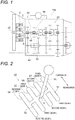
Fig. 1] Fig. 1 is a schematic diagram showing an example of a dual clutch transmission to which a clutch connection/disconnection device of the present invention is applied. - [
Fig. 2] Fig. 2 is a perspective view showing schematically an example of a shift operating device. - [
Fig. 3] Fig. 3 is a schematic diagram showing a clutch connection/disconnection device according to a first embodiment of the present invention. - [
Fig. 4] Fig. 4 is a schematic diagram of the first embodiment showing an operation when a shift lever is tilted forwards in a state that a clutch pedal is kept depressed. - [
Fig. 5] Fig. 5 is a schematic diagram of the first embodiment showing an operation when the first clutch is engaged in response to the clutch pedal being returned in a state that the shift lever is kept tilted forwards. - [
Fig. 6] Fig. 6 is a schematic diagram of the first embodiment showing an operation when the clutch pedal is depressed in a state that the first clutch is kept engaged. - [
Fig. 7] Fig. 7 is a schematic diagram of the first embodiment showing an operation when the clutch pedal is depressed in a state that the shift lever is in a neutral position and the first clutch is kept engaged. - [
Fig. 8] Fig. 8 is a schematic diagram of the first embodiment showing an operation when the shift lever is tilted rearwards in a state that the clutch pedal is kept depressed. - [
Fig. 9] Fig. 9 is a schematic diagram of the first embodiment showing an operation when the second clutch is engaged in response to the clutch pedal being returned in a state that the shift lever is kept tilted rearwards. - [
Fig. 10] Fig. 10 is a schematic diagram of the first embodiment showing an operation when the clutch pedal is depressed in a state that the second clutch is kept engaged. - [
Fig. 11] Fig. 11 is a schematic diagram of the first embodiment showing an operation when the clutch pedal is depressed in a state that the shift lever is in the neutral position and the second clutch is kept engaged. - [
Fig. 12] Fig. 12 is a schematic diagram showing a clutch connection/disconnection device according to a second embodiment of the present invention. - [
Fig. 13] Fig. 13 is a schematic diagram of the second embodiment showing an operation when a shift lever is tilted forwards in a state that a clutch pedal is kept depressed. - [
Fig. 14] Fig. 14 is a schematic diagram of the second embodiment showing an operation when a first clutch is engaged in response to the clutch pedal being returned in a state that the shift lever is kept tilted forwards. - [
Fig. 15] Fig. 15 is a schematic diagram of the second embodiment showing an operation when the clutch pedal is depressed in a state that the first clutch is kept engaged. - [
Fig. 16] Fig. 16 is a schematic diagram of the second embodiment showing an operation when the clutch pedal is depressed in a state that the shift lever is in a neutral position and the first clutch is kept engaged. - [
Fig. 17] Fig. 17 is a schematic diagram of the second embodiment showing an operation when the shift lever is tilted rearwards in a state that the clutch pedal is kept depressed. - [
Fig. 18] Fig. 18 is a schematic diagram of the second embodiment showing an operation when a second clutch is engaged in response to the clutch pedal being returned in a state that the shift lever is kept tilted rearwards. - [
Fig. 19] Fig. 19 is a schematic diagram of the second embodiment showing an operation when the clutch pedal is depressed in a state that the second clutch is kept engaged. - [
Fig. 20] Fig. 20 is a schematic diagram of the second embodiment showing an operation when the clutch pedal is depressed in a state that the shift lever is in the neutral position and the second clutch is kept engaged. - Hereinafter, a first embodiment of the present invention will be described in detail by reference to the drawings.
- As shown in
Fig. 1 , a dual clutch manual transmission (a dual clutch transmission) TM includes amain transmission mechanism 20, asplitter mechanism 41 which is provided on an input side of themain transmission mechanism 20, and adual clutch 2 which is provided on an input side of thesplitter mechanism 41 and changes gears in response to an operation of a shift lever SL (refer toFig. 2 ) of ashift operating device 50. Thedual clutch 2 has afirst clutch 5 and asecond clutch 6, and themain transmission mechanism 20 has a high-gear side path 45 and a low-gear side path 46 as power transmission paths. When thefirst clutch 5 is engaged, power of aninput shaft 42 which is connected to an engine (whose illustration is omitted) is inputted from thefirst clutch 5 into afirst shaft 43 of thesplitter mechanism 41 and is then transmitted to the high-gear side path 45. When thesecond clutch 6 is engaged, the power of theinput shaft 42 is inputted from thesecond clutch 6 into asecond shaft 44 of thesplitter mechanism 41 and is then transmitted to the high-gear side path 45. Namely, the power transmission path of themain transmission mechanism 20 is switched to the high-gear side path 45 in response to thefirst clutch 5 being engaged and to the low-gear side path 46 in response to thesecond clutch 6 being engaged. - As shown in
Fig. 2 , theshift operating device 50 includes a plurality of H-shapedgates 51 and the shift lever SL which can be moved in the H-shapedgates 51. A selectingpath 53 is provided in a selecting direction (a side-to-side direction of a vehicle) of the H-shapedgates 51, and a neutral position N is set in a center of the selectingpath 53, the neutral position N corresponding to a neutral mode. Four shifting paths 54 to 57 are provided in a shifting direction (a fore-and-aft direction) of the H-shapedgates 51 so as to intersect the selectingpath 53 at right angles. Shift positions are provided at end portions of the four shifting paths 54 to 57, and the shifting positions correspond to six forward gears (a first gear L to a third gear H) and two reverse gears (a reverse gear L, a reverse gear H). Each of the front side (one side) end portions of each of the shifting paths 54 to 57 corresponds to the high-gear side shift positions (the reverse gear H, the first gear H, the second gear H, the third gear H), and each of the rear side (the other side) end portions corresponds to the low-gear side shift positions (the reverse gear L, the first gear L, the second gear L, the third gear L). The shift lever SL can be moved to an arbitrary shift position among the high-gear shift positions and the low-gear shift positions, and the dual clutch transmission TM changes gears in response to a movement of the shift lever SL. For example, when the shift lever SL is moved to the high-gear shift position, power is transmitted to the high-gear side path 45 of the main transmission mechanism 20 (refer toFig. 1 ), and a gear combination corresponding to the shift position is selected in the high-gear side path 45. In addition, when the shift lever SL is moved to the low-gear shift position, power is transmitted to the low-gear side path 46, and a gear combination corresponding to the shift position is selected in the low-gear side path 46. A detailed description of the gear combinations at each of the shift positions will be omitted. - As shown in
Fig. 3 , a clutch connection/disconnection device 1 includes aclutch pedal mechanism 3 and ahydraulic circuit 4. - The
first clutch 5 of thedual clutch 2 includes afirst pressure plate 5a and a firstclutch disc 5b. Thefirst pressure plate 5a is fixed to a crankshaft (whose illustration is omitted) of the engine and rotates together with the crankshaft. The firstclutch disc 5b is fixed to an input end side of a first input shaft (whose illustration is omitted) and rotates together with the first input shaft. Thefirst clutch 5 is coupled to thehydraulic circuit 4, and thefirst pressure plate 5a is pushed to move towards the firstclutch disc 5b and is pressed to contact with the firstclutch disc 5b. This allows the power of the engine to be transmitted to the first input shaft. On the other hand, thefirst clutch 5 is coupled to thehydraulic circuit 4, and thefirst pressure plate 5a is pulled to move away from the firstclutch disc 5b and is disengaged from the firstclutch disc 5b. - The
second clutch 6 includes asecond pressure plate 6a and a secondclutch disc 6b. Thesecond pressure plate 6a is fixed to the crankshaft (whose illustration is omitted) of the engine and rotates together with the crankshaft. The secondclutch disc 6b is fixed to an input end side of a second input shaft (whose illustration is omitted) and rotates together with the second input shaft. Thesecond clutch 6 is coupled to thehydraulic circuit 4, and thesecond pressure plate 6a is pushed to move towards the secondclutch disc 6b and is pressed to contact with the secondclutch disc 6b. This allows the power of the engine to be transmitted to the second input shaft. On the other hand, thesecond clutch 6 is coupled to thehydraulic circuit 4, and thesecond pressure plate 6a is pulled to move away from the secondclutch disc 6b and is disengaged from the secondclutch disc 6b. - The
clutch pedal mechanism 3 is a mechanism for engaging and disengaging thefirst clutch 5 and thesecond clutch 6 and is connected to thehydraulic circuit 4. Theclutch pedal mechanism 3 includes aclutch pedal 3a, anarm 3b, anarm support portion 3c and a spring (a biasing device) 3d. - The
clutch pedal 3a is fixed to one end of thearm 3b. Thisclutch pedal 3a is depressed from a predetermined initial position to disengage thefirst clutch 5 and thesecond clutch 6. Thearm 3b is supported to be rotatable by thearm support portion 3c. Thearm 3b is inclined in one direction (in a clockwise direction in Figure) while stretching thespring 3d in response to theclutch pedal 3a being depressed. In addition, thearm 3b is inclined in the other direction (in a counterclockwise direction in Figure), by biasing force produced when the stretchedspring 3d restores (shrinks) in response to the depression of theclutch pedal 3a being released, to bring theclutch pedal 3a back to its original position. Namely, thespring 3d biases theclutch pedal 3a to its initial position and returns theclutch pedal 3a to its initial position when the depression is released. - The
hydraulic circuit 4 transmits, to thefirst clutch 5 and thesecond clutch 6, a depressed action of theclutch pedal 3a and a restoring action in which the depressedclutch pedal 3a is returned by thespring 3d. Thehydraulic circuit 4 includes a pedal-side hydraulic circuit (a pedal-side transmission circuit) 7, a first clutch-side hydraulic circuit (a first clutch-side transmission circuit) 8, a second clutch-side hydraulic circuit (a second clutch-side transmission circuit) 9, a switching valve (a switching device) 10 andcheck valves - The pedal-side
hydraulic circuit 7 is connected to theclutch pedal mechanism 3 and makes up a circuit on the side of theclutch pedal mechanism 3. A path of the pedal-sidehydraulic circuit 7 is divided into three paths and the three paths are connected to the switchingvalve 10 and thecheck valves hydraulic circuit 7 includes ahydraulic cylinder 7a which is provided on the path before it is divided into the three paths and transmits the depressed action of theclutch pedal 3a and the restoring action of the depressedclutch pedal 3a from theclutch pedal mechanism 3 by the action of thehydraulic cylinder 7a. Thehydraulic cylinder 7a is pulled by the depressed action of theclutch pedal 3a and forms flows from the changingvalve 10 and thecheck valves clutch pedal mechanism 3. On the other hand, thehydraulic cylinder 7a is pushed by the restoring action of the depressedclutch pedal 3a to form a flow from theclutch pedal mechanism 3 towards the switchingvalve 10. - The first clutch-side
hydraulic circuit 8 is connected to thefirst clutch 5 and makes up a circuit on the side of thefirst clutch 5. A path of the first clutch-sidehydraulic circuit 8 is divided into two paths and the two paths are connected to the switchingvalve 10 and thecheck valve 11 respectively. The first clutch-sidehydraulic circuit 8 includes ahydraulic cylinder 8a which is provided on the path before it is divided into the two paths and transmits the depressed action of theclutch pedal 3a and the restoring action of the depressedclutch pedal 3a to thefirst clutch 5 by the action of thehydraulic cylinder 8a. - The second clutch-side
hydraulic circuit 9 is connected to thesecond clutch 6 and makes up a circuit on the side of thesecond clutch 6. A path of the second clutch-sidehydraulic circuit 9 is divided into two paths and the two paths are connected to the switchingvalve 10 and thecheck valve 12 respectively. The second clutch-sidehydraulic circuit 9 includes ahydraulic cylinder 9a which is provided on the path before it is divided into the two paths and transmits the depressed action of theclutch pedal 3a and the restoring action of the depressedclutch pedal 3a to thesecond clutch 6 by the action of thehydraulic cylinder 9a. - The switching
valve 10 has three ports which are situated in three different positions. The switchingvalve 10 adopts a spool of a closed center type and a spring-centered restoring method. The operating method of the switchingvalve 10 is manual. Each of the ports of the switchingvalve 10 is connected to the pedal-sidehydraulic circuit 7, the first clutch-sidehydraulic circuit 8 or the second clutch-sidehydraulic circuit 9. The switchingvalve 10 disconnects the pedal-sidehydraulic circuit 7 from the first clutch-sidehydraulic circuit 8 and the second clutch-sidehydraulic circuit 9 when the shift lever SL is in the neutral state where the shift lever SL is not tilted forwards or backwards (is moved neither to the front nor to the rear) (refer toFig. 3 ). Then, the switchingvalve 10 connects the first clutch-sidehydraulic circuit 8 to the pedal-sidehydraulic circuit 7 when the shift lever SL is tilted forwards (is moved to the front) to move the switching valve itself forwards (move leftwards in Figure) (refer toFig. 4 ). In addition, the switchingvalve 10 connects the second clutch-sidehydraulic circuit 9 to the pedal-sidehydraulic circuit 7 when the shift lever SL is tilted rearwards (is moved to the rear) to move the switching valve itself rearwards (move rightwards in Figure) (refer toFig. 8 ). - The switching
valve 10 is coupled to the shift lever SL by way of acoupling mechanism 40 which is made up of a link or a wire, the ports of the switchingvalve 10 are switched over in association with the shift lever SL being tilted in the fore-and-aft direction. The switchingvalve 10 may be made up of a solenoid valve, and a signal line may be provided in place of thecoupling mechanism 40, so that the solenoid valve is switched by a control signal which corresponds to the fore-and-aft tilting of the shift lever SL. - The
check valve 11 is connected to both the pedal-sidehydraulic circuit 7 and the first clutch-sidehydraulic circuit 8 respectively. Thischeck valve 11 permits a flow from the pedal-sidehydraulic circuit 7 to the first clutch-sidehydraulic circuit 8 but prohibits a flow from the first clutch-sidehydraulic circuit 8 to the pedal-sidehydraulic circuit 7. - The
check valve 12 is connected to both the pedal-sidehydraulic circuit 7 and the second clutch-sidehydraulic circuit 9 respectively. Thischeck valve 12 permits a flow from the pedal-sidehydraulic circuit 7 to the second clutch-sidehydraulic circuit 9 but prohibits a flow from the second clutch-sidehydraulic circuit 9 to the pedal-sidehydraulic circuit 7. - Next, the operation of the clutch connection/disconnection device 1 will be described.
- As shown in
Fig. 4 , when the shift lever SL is tilted forwards in a state that theclutch pedal 3a is kept depressed, the switchingvalve 10 moves forwards (moves leftwards in Figure) to connect the first clutch-sidehydraulic circuit 8 to the pedal-sidehydraulic circuit 7. - As shown in
Fig. 5 , when theclutch pedal 3a is returned in a state that the shift lever SL is kept tilted forwards, the restoring action of theclutch pedal 3a actuates thehydraulic cylinder 7a to pressurize the pedal-sidehydraulic circuit 7. This forms a flow from theclutch pedal mechanism 3 to the switchingvalve 10. Then, a movement of thehydraulic cylinder 7a actuates thehydraulic cylinder 8a to pressurize the first clutch-side hydraulic circuit 8.This forms a flow from the switchingvalve 10 to thefirst clutch 5. In addition, the pushing action of thehydraulic cylinder 8a engages thefirst clutch 5. In this case, the second clutch-sidehydraulic circuit 9 is not pressurized and thesecond clutch 6 is kept disengaged due to functioning the switchingvalve 10 and thecheck valve 12. - As shown in
Fig. 6 , when theclutch pedal 3a is depressed in a state that thefirst clutch 5 is kept engaged, the depressing action of theclutch pedal 3a actuates thehydraulic cylinder 7a to depressurize the pedal-sidehydraulic circuit 7. This forms flows from the switchingvalve 10 and thecheck valve 11 to theclutch pedal mechanism 3. Then, a movement of thehydraulic cylinder 7a actuates thehydraulic cylinder 8a to depressurize the first clutch-side hydraulic circuit 8.This forms flows from thefirst clutch 5 to the switchingvalve 10 and thecheck valve 11. In addition, the pulling action of thehydraulic cylinder 8a disengages thefirst clutch 5. In this case, the second clutch-sidehydraulic circuit 9 is not pressurized and thesecond clutch 6 is kept disengaged due to the pedal-sidehydraulic circuit 7 being depressurized. - Alternatively, as shown in
Fig. 7 , when the shift lever SL is returned to the neutral state, the switchingvalve 10 cuts off the communication between the pedal-sidehydraulic circuit 7 and the first clutch-sidehydraulic circuit 8 while keeping the pedal-sidehydraulic circuit 7 and the second clutch-sidehydraulic circuit 9 disconnected. Thereafter, when theclutch pedal 3a is depressed in a state that thefirst clutch 5 is kept engaged, the depressing action of theclutch pedal 3a actuates thehydraulic cylinder 7a to depressurize the pedal-sidehydraulic circuit 7. This forms a flow from thecheck valve 11 to theclutch pedal mechanism 3. Then, a movement of thehydraulic cylinder 7a actuates thehydraulic cylinder 8a to depressurize the first clutch-sidehydraulic circuit 8. This forms a flow from thefirst clutch 5 to thecheck valve 11. In addition, the pulling action of thehydraulic cylinder 8a disengages thefirst clutch 5. In this case, the second clutch-sidehydraulic circuit 9 is not pressurized and thesecond clutch 6 is kept disengaged due to the pedal-sidehydraulic circuit 7 being depressurized. - As shown in
Fig. 8 , when the shift lever SL is tilted rearwards in a state that theclutch pedal 3a is kept depressed, the switchingvalve 10 moves rearwards (moves rightwards in Figure) to connect the second clutch-sidehydraulic circuit 9 to the pedal-sidehydraulic circuit 7. - As shown in
Fig. 9 , when theclutch pedal 3a is returned in a state that the shift lever SL is kept tilted rearwards, the restoring action of theclutch pedal 3a actuates thehydraulic cylinder 7a to pressurize the pedal-sidehydraulic circuit 7. This forms a flow from theclutch pedal mechanism 3 to the switchingvalve 10. Then, a movement of thehydraulic cylinder 7a actuates thehydraulic cylinder 9a to pressurize the second clutch-side hydraulic circuit 9.This forms a flow from the switchingvalve 10 to thesecond clutch 6. In addition, the pushing action of thehydraulic cylinder 9a engages thesecond clutch 6. In this case, the first clutch-sidehydraulic circuit 8 is not pressurized and thefirst clutch 5 is kept disengaged due to functioning the switchingvalve 10 and thecheck valve 11. - As shown in
Fig. 10 , when theclutch pedal 3a is depressed in a state that thesecond clutch 6 is kept engaged, the depressing action of theclutch pedal 3a actuates thehydraulic cylinder 7a to depressurize the pedal-sidehydraulic circuit 7. This forms flows from the switchingvalve 10 and thecheck valve 12 to theclutch pedal mechanism 3. Then, a movement of thehydraulic cylinder 7a actuates thehydraulic cylinder 9a to depressurize the second clutch-side hydraulic circuit 9.This forms flows from thesecond clutch 6 to the switchingvalve 10 and thecheck valve 12. In addition, the pulling action of thehydraulic cylinder 9a disengages thesecond clutch 6. In this case, the first clutch-sidehydraulic circuit 8 is not pressurized and thefirst clutch 5 is kept disengaged due to the pedal-sidehydraulic circuit 7 being depressurized. - Alternatively, as shown in
Fig. 11 , when the shift lever SL is returned to the neutral state, the switchingvalve 10 cuts off the communication between the pedal-sidehydraulic circuit 7 and the second clutch-sidehydraulic circuit 9 while keeping the pedal-sidehydraulic circuit 7 and the first clutch-sidehydraulic circuit 8 disconnected. Thereafter, when theclutch pedal 3a is depressed in a state that thesecond clutch 6 is kept engaged, the depressing action of theclutch pedal 3a actuates thehydraulic cylinder 7a to depressurize the pedal-sidehydraulic circuit 7. This forms a flow from thecheck valve 12 to theclutch pedal mechanism 3. Then, a movement of thehydraulic cylinder 7a actuates thehydraulic cylinder 9a to depressurize the second clutch-sidehydraulic circuit 9. This forms a flow from thesecond clutch 6 to thecheck valve 12. In addition, the pulling action of thehydraulic cylinder 9a disengages thesecond clutch 6. In this case, the first clutch-sidehydraulic circuit 8 is not pressurized and thefirst clutch 5 is kept disengaged due to the pedal-sidehydraulic circuit 7 being depressurized. - According to this embodiment, when the shift lever SL is tilted forwards, the switching
valve 10 connects the first clutch-sidehydraulic circuit 8 to the pedal-sidehydraulic circuit 7. In this case, the restoring action of the depressedclutch pedal 3a is transmitted to thefirst clutch 5 by way of the pedal-sidehydraulic circuit 7 and the first clutch-sidehydraulic circuit 8. Thus, thefirst clutch 5 is engaged. - On the other hand, when the shift lever SL is tilted rearwards, the switching
valve 10 connects the second clutch-sidehydraulic circuit 9 to the pedal-sidehydraulic circuit 7. In this case, the restoring action of the depressedclutch pedal 3a is transmitted to thesecond clutch 6 by way of the pedal-sidehydraulic circuit 7 and the second clutch-sidehydraulic circuit 9. Thus, thesecond clutch 6 is engaged. - In this way, the clutches are selected in response to whether forwards or rearwards the shift lever SL being tilted. Consequently, similarly in case of the single clutch, the clutches to be engaged or disengaged can be switched by operating the
clutch pedal 3a and the shift lever SL without requiring a special operation to switch the clutches to be engaged or disengaged. - The splitter mechanism 41 (refer to
Fig. 1 ) is a mechanism provided to switch high/low between a changing step of gears of themain transmission mechanism 20, and the clutches to be selected can be determined whether forwards or rearwards the shift lever SL being tilted as described above. Thus, the splitter mechanism functions properly in response to the switching of the clutches described above. - Next, a second embodiment of the present invention will be described in detail by reference to the drawings. A clutch connection/
disconnection device 21 according to the second embodiment is such that the clutch connection/disconnection device 1 according to the first embodiment is modified andlink mechanisms - The clutch connection/
disconnection device 21 shown inFig. 12 includes adual clutch 22, aclutch pedal mechanism 23, ahydraulic circuit 24 and thelink mechanisms - The
dual clutch 22 includes a first clutch 25 and asecond clutch 26. - The first clutch 25 includes a
first pressure plate 25a and a firstclutch disc 25b. The first clutch 25 is coupled to thehydraulic circuit 24 by way of thelink mechanism 33, and thefirst pressure plate 25a is pushed to move towards the firstclutch disc 25b and is pressed to contact with the firstclutch disc 25b. This allows power of an engine to be transmitted to a first input shaft (whose illustration is omitted). In addition, the first clutch 25 is coupled to thehydraulic circuit 24 by way of thelink mechanism 33, and thefirst pressure plate 25a is pulled to move away from the firstclutch disc 25b and is disengaged from the firstclutch disc 25b. - The second clutch 26 includes a
second pressure plate 26a and a secondclutch disc 26b. The second clutch 26 is coupled to thehydraulic circuit 24 by way of thelink mechanism 34, and thesecond pressure plate 26a is pushed to move towards the secondclutch disc 26b and is pressed to contact with the secondclutch disc 26b. This allows the power of the engine to be transmitted to a second input shaft (whose illustration is omitted). In addition, the second clutch 26 is coupled to thehydraulic circuit 24 by way of thelink mechanism 34, and thesecond pressure plate 26a is pulled to move away from the secondclutch disc 26b and is disengaged from the secondclutch disc 26b. - The
clutch pedal mechanism 23 includes aclutch pedal 23a, anarm 23b, anarm support portion 23c and a spring (a biasing device) 23d. - The
arm 23b is inclined in one direction (in a clockwise direction inFig. 13 ) while shrinking thespring 23d in response to theclutch pedal 23a being depressed from a predetermined initial position. In addition, thearm 23b is inclined in the other direction (in a counterclockwise direction in Figure), by biasing force produced when the shrunkspring 23d restores (stretches) in response to the depression of theclutch pedal 3a being released, to bring theclutch pedal 23a back to its original position. Namely, thespring 23d biases theclutch pedal 23a to its initial position and returns theclutch pedal 23a to its initial position when the depression is released. - The
hydraulic circuit 24 includes a pedal-side hydraulic circuit (a pedal-side transmission circuit) 27, a first clutch-side hydraulic circuit (a first clutch-side transmission circuit) 28, a second clutch-side hydraulic circuit (a second clutch-side transmission circuit) 29, a switching valve (a switching device) 30 andcheck valves - A path of the pedal-side
hydraulic circuit 27 is divided into three paths and the three paths are connected to a switchingvalve 30 and thecheck valves hydraulic circuit 27 includes ahydraulic cylinder 27a which is provided on the path before it is divided into the three paths. Thehydraulic cylinder 27a is pushed by the depressed action of theclutch pedal 23a and forms flows from theclutch pedal 23 towards the switchingvalve 30 and thecheck valves hydraulic cylinder 27a is pulled by the restoring action (returning action) of the depressedclutch pedal 23 to form a flow from the switchingvalve 30 towards theclutch pedal mechanism 23. - The switching
valve 30 connects the first clutch-sidehydraulic circuit 28 to the pedal-sidehydraulic circuit 27 when the shift lever SL is tilted forwards to move the switching valve itself forwards (move leftwards in Figure) (refer toFig. 13 ). In addition, the switchingvalve 30 connects the second clutch-sidehydraulic circuit 29 to the pedal-sidehydraulic circuit 27 when the shift lever SL is tilted rearwards to move the switching valve itself rearwards (move rightwards in Figure) (refer toFig. 17 ). - The
check valve 31 is connected to both the pedal-sidehydraulic circuit 27 and the first clutch-sidehydraulic circuit 28 respectively. Thischeck valve 31 permits a flow from the first clutch-sidehydraulic circuit 28 to the pedal-sidehydraulic circuit 27 but prohibits a flow from the pedal-sidehydraulic circuit 27 to the first clutch-sidehydraulic circuit 28. - The
check valve 32 is connected to both the pedal-sidehydraulic circuit 27 and the second clutch-sidehydraulic circuit 29 respectively. Thischeck valve 32 permits a flow from the second clutch-sidehydraulic circuit 29 to the pedal-sidehydraulic circuit 27 but prohibits a flow from the pedal-sidehydraulic circuit 27 to the second clutch-sidehydraulic circuit 29. - The
link mechanism 33 is provided between the first clutch-sidehydraulic circuit 28 and thefirst clutch 25. Thislink mechanism 33 converts pushing force to pulling force of the first clutch-sidehydraulic circuit 28 to transmit the pulling force to thefirst clutch 25. In addition, thelink mechanism 33 converts pulling force to pushing force of the first clutch-sidehydraulic circuit 28 to transmit the pushing force to thefirst clutch 25. - The
link mechanism 34 is provided between the second clutch-sidehydraulic circuit 29 and thesecond clutch 26. Thislink mechanism 34 converts pushing force to pulling force of the second clutch-sidehydraulic circuit 29 to transmit the pulling force to thesecond clutch 26. In addition, thelink mechanism 34 converts pulling force to pushing force of the second clutch-sidehydraulic circuit 29 to transmit the pushing force to thesecond clutch 26. - Next, the operation of the clutch connection/
disconnection device 21 will be described. - As shown in
Fig. 13 , when the shift lever SL is tilted forwards in a state that theclutch pedal 23a is kept depressed, the switchingvalve 30 moves forwards (moves leftwards in Figure) to connect the first clutch-sidehydraulic circuit 28 to the pedal-sidehydraulic circuit 27. - As shown in
Fig. 14 , when theclutch pedal 23 is returned in a state that the shift lever SL is kept tilted forwards, the restoring action of theclutch pedal 23a actuates thehydraulic cylinder 27a to depressurize the pedal-sidehydraulic circuit 27. This forms a flow from the switchingvalve 30 to theclutch pedal mechanism 23. Then, a movement of thehydraulic cylinder 27a actuates ahydraulic cylinder 28a to pressurize the first clutch-sidehydraulic circuit 28. This forms a flow from the first clutch 25 to the switchingvalve 30. In addition, a pulling action of thehydraulic cylinder 28a is converted to a pushing action by thelink mechanism 33 to engage thefirst clutch 25. In this case, the second clutch-sidehydraulic circuit 29 is not pressurized and the second clutch 26 is kept disengaged due to functioning the switchingvalve 30 and thecheck valve 32. - As shown in
Fig. 15 , when theclutch pedal 23 is depressed in a state that the first clutch 25 is kept engaged, the depressing action of theclutch pedal 23a actuates thehydraulic cylinder 27a to pressurize the pedal-sidehydraulic circuit 27. This forms flows from theclutch pedal mechanism 23 to the switchingvalve 30 and thecheck valve 31. Then, a movement of thehydraulic cylinder 27a actuates thehydraulic cylinder 28a to depressurize the first clutch-sidehydraulic circuit 28. This forms flows from the switchingvalve 30 and thecheck valve 31 to thefirst clutch 25. In addition, a pushing action of thehydraulic cylinder 28a is converted to a pulling action by thelink mechanism 33 to disengage thefirst clutch 25. In this case, the second clutch-sidehydraulic circuit 29 is not depressurized and the second clutch 26 is kept disengaged due to the pedal-sidehydraulic circuit 27 being pressurized. - Alternatively, as shown in
Fig. 16 , when the shift lever SL is returned to a neutral state, the switchingvalve 30 cuts off the communication between the pedal-sidehydraulic circuit 27 and the first clutch-sidehydraulic circuit 28 while keeping the pedal-sidehydraulic circuit 27 and the second clutch-sidehydraulic circuit 29 disconnected. Thereafter, when theclutch pedal 23a is depressed in a state that the first clutch 25 is kept engaged, the depressing action of theclutch pedal 23a actuates thehydraulic cylinder 27a to pressurize the pedal-sidehydraulic circuit 27. This forms a flow from theclutch pedal mechanism 23 to thecheck valve 31. Then, a movement of thehydraulic cylinder 27a actuates ahydraulic cylinder 28a to pressurize the first clutch-sidehydraulic circuit 28. This forms a flow from thecheck valve 31 to thefirst clutch 25. In addition, a pushing action of thehydraulic cylinder 28a is converted to a pulling action by thelink mechanism 33 to disengage thefirst clutch 25. In this case, the second clutch-sidehydraulic circuit 29 is not depressurized and thesecond clutch 6 is kept disengaged due to the pedal-sidehydraulic circuit 27 being pressurized. - As shown in
Fig. 17 , when the shift lever SL is tilted rearwards in a state that theclutch pedal 23a is kept depressed, the switchingvalve 30 moves rearwards (moves rightwards in Figure) to connect the second clutch-sidehydraulic circuit 29 to the pedal-sidehydraulic circuit 27. - As shown in
Fig. 18 , when theclutch pedal 23a is returned in a state that the shift lever SL is kept tilted rearwards, the restoring action of theclutch pedal 23a actuates thehydraulic cylinder 27a to depressurize the pedal-sidehydraulic circuit 27. This forms a flow from the switchingvalve 30 to theclutch pedal mechanism 23. Then, a movement of thehydraulic cylinder 27a actuates thehydraulic cylinder 29a to depressurize the second clutch-sidehydraulic circuit 29. This forms a flow from the second clutch 26 to the switchingvalve 30. In addition, a pulling action of ahydraulic cylinder 29a is converted to a pushing action by thelink mechanism 34 to engage thesecond clutch 26. In this case, the first clutch-sidehydraulic circuit 28 is not depressurized and the first clutch 25 is kept disengaged due to functioning the switchingvalve 30 and thecheck valve 31. - As shown in
Fig. 19 , when theclutch pedal 23a is depressed in a state that the second clutch 26 is kept engaged, the depressing action of theclutch pedal 23a actuates thehydraulic cylinder 27a to pressurize the pedal-sidehydraulic circuit 27. This forms flows from theclutch pedal mechanism 23 to the switchingvalve 30 and thecheck valve 32. Then, a movement of thehydraulic cylinder 27a actuates thehydraulic cylinder 29a to pressurize the second clutch-sidehydraulic circuit 29. This forms flows from the switchingvalve 30 and thecheck valve 32 to thesecond clutch 26. In addition, a pushing action of thehydraulic cylinder 29a is converted to a pulling action by thelink mechanism 34 to disengage thesecond clutch 26. In this case, the first clutch-sidehydraulic circuit 28 is not depressurized and thefirst clutch 5 is kept disengaged due to the pedal-sidehydraulic circuit 27 being pressurized. - Alternatively, as shown in
Fig. 20 , when the shift lever SL is returned to the neutral state, the switchingvalve 30 cuts off the communication between the pedal-sidehydraulic circuit 27 and the second clutch-sidehydraulic circuit 29 while keeping the pedal-sidehydraulic circuit 27 and the first clutch-sidehydraulic circuit 28 disconnected. Thereafter, when theclutch pedal 23a is depressed in a state that the second clutch 26 is kept engaged, the depressing action of theclutch pedal 23a actuates thehydraulic cylinder 27a to pressurize the pedal-sidehydraulic circuit 27. This forms a flow from theclutch pedal mechanism 23 to thecheck valve 32. Then, a movement of thehydraulic cylinder 27a actuates thehydraulic cylinder 29a to pressurize the second clutch-sidehydraulic circuit 29. This forms a flow from thecheck valve 32 to thesecond clutch 26. In addition, a pushing action of thehydraulic cylinder 29a is converted to a pulling action by thelink mechanism 34 to disengage thesecond clutch 26. In this case, the first clutch-sidehydraulic circuit 28 is not pressurized and the first clutch 25 is kept disengaged due to the pedal-sidehydraulic circuit 27 being pressurized. - According to this embodiment, similarly to the first embodiment, the clutches are selected in response to whether forwards or rearwards the shift lever SL being tilted.
- Thus, while the embodiments to which the invention made by the inventor is applied have been described heretofore, the invention is not limited at all by the description and the drawings which make up part of the disclosure of the invention based on the embodiments. Namely, other embodiments, examples and operating techniques which are made based on the embodiments described herein by those skilled in the art to which the invention pertains should all, of course, be included in the scope of the invention.
-
- 1, 21 clutch connection/disconnection device
- 2, 22 dual clutch
- 3a, 23a clutch pedal
- 3d, 23d spring (biasing device)
- 5, 25 first clutch
- 6, 26 second clutch
- 7, 27 pedal-side hydraulic circuit (pedal-side transmission circuit)
- 8,28 first clutch-side hydraulic circuit (first clutch-side transmission circuit)
- 9, 29 second clutch-side hydraulic circuit (second clutch-side transmission circuit)
- 10, 30 switching valve (switching device)
- 20 main transmission mechanism
- 45 high-gear side path
- 46 low-gear side path
- SL shift lever
- TM dual clutch transmission
Claims (1)
- A clutch connection/disconnection device for a dual clutch transmission, a dual clutch having a first clutch and a second clutch, the dual clutch being provided on an input side of a main transmission mechanism, the power transmission mechanism being switched to a high-gear side path by causing the first clutch to be engaged, the power transmission mechanism being switched to a low-gear side path by causing the second clutch to be engaged, and the clutch connection/disconnection device changing gears in response to a movement of a shift lever which can be moved to one of an arbitrary shift position among a high-gear side shift positions as one side and a low-gear side shift positions as the other side, the clutch connection/disconnection device comprising:a clutch pedal which is depressed to move from a predetermined initial position;a biasing device for biasing the clutch pedal to the initial position and for returning the clutch pedal to the initial position in response to releasing a depression;a pedal-side transmission circuit for transmitting, from the clutch pedal, a restoring action in which the clutch pedal being depressed is returned to the initial position by the biasing device;a first clutch-side transmission circuit for transmitting the restoring action to the first clutch;a second clutch-side transmission circuit for transmitting the restoring action to the second clutch; anda switching device for connecting the first clutch-side transmission circuit to the pedal-side transmission circuit when the shift lever is moved to the one side and for connecting the second clutch-side transmission circuit to the pedal-side transmission circuit when the shift lever is moved to the other side, andwherein the first clutch is engaged in response to the restoring action being transmitted from the first clutch-side transmission circuit, andwherein the second clutch is engaged in response to the restoring action being transmitted from the second clutch-side transmission circuit.
Applications Claiming Priority (2)
| Application Number | Priority Date | Filing Date | Title |
|---|---|---|---|
| JP2014199056A JP2016070339A (en) | 2014-09-29 | 2014-09-29 | Clutch connection/disconnection device of dual-clutch type transmission |
| PCT/JP2015/077596 WO2016052553A1 (en) | 2014-09-29 | 2015-09-29 | Clutch connection/disconnection device for dual clutch transmission |
Publications (3)
| Publication Number | Publication Date |
|---|---|
| EP3203121A1 true EP3203121A1 (en) | 2017-08-09 |
| EP3203121A4 EP3203121A4 (en) | 2018-05-30 |
| EP3203121B1 EP3203121B1 (en) | 2022-02-16 |
Family
ID=55630578
Family Applications (1)
| Application Number | Title | Priority Date | Filing Date |
|---|---|---|---|
| EP15847474.2A Active EP3203121B1 (en) | 2014-09-29 | 2015-09-29 | Clutch connection/disconnection device for dual clutch transmission |
Country Status (5)
| Country | Link |
|---|---|
| US (1) | US10174796B2 (en) |
| EP (1) | EP3203121B1 (en) |
| JP (1) | JP2016070339A (en) |
| CN (1) | CN107076294B (en) |
| WO (1) | WO2016052553A1 (en) |
Family Cites Families (23)
| Publication number | Priority date | Publication date | Assignee | Title |
|---|---|---|---|---|
| US3774460A (en) * | 1972-06-09 | 1973-11-27 | Deere & Co | Compact transmission structure |
| JPS5676725A (en) * | 1979-11-24 | 1981-06-24 | Kubota Ltd | Device for operating double clutch |
| JPS5940951A (en) * | 1982-09-01 | 1984-03-06 | Fuji Heavy Ind Ltd | Transmission operating mechanism for vehicle with automatic clutch |
| US4513850A (en) | 1983-02-09 | 1985-04-30 | Allis-Chalmers Corporation | Electrohydraulic power shift transmission system |
| DE3343827A1 (en) * | 1983-12-03 | 1985-06-13 | Porsche Ag | CONTROL SYSTEM FOR A DOUBLE COUPLING OF A POWER-SWITCHING VEHICLE TRANSMISSION |
| DE3414107A1 (en) | 1984-04-13 | 1985-10-24 | Rudolf Prof. Dr.-Ing. 6100 Darmstadt Franke | Variable-speed spur-gear transmission shiftable under load |
| US5094329A (en) * | 1989-08-10 | 1992-03-10 | General Motors Corporation | Dual flywheel for a transmission input clutch |
| US5002166A (en) * | 1989-09-14 | 1991-03-26 | Automotive Products Plc | Dual mode motor vehicle clutch control system |
| GB9521620D0 (en) * | 1995-10-21 | 1996-01-03 | Eaton Corp | Compound transmission with repeat or double-I shift pattern |
| DE10004286B4 (en) * | 1999-09-30 | 2010-10-14 | Zf Sachs Ag | Coupling device with a hydrodynamic coupling and at least two friction clutches |
| US6427550B1 (en) | 2001-01-12 | 2002-08-06 | New Venture Gear, Inc. | Twin clutch automated transaxle |
| DE10113161A1 (en) * | 2001-03-19 | 2002-09-26 | Hydraulik Ring Gmbh | Actuator for automated discrete gearboxes, preferably for motor vehicles, has only one valve for each of rotation and displacement of the shifting shaft and valve activates shifting element |
| DE102004009834A1 (en) | 2003-03-03 | 2004-09-16 | Luk Lamellen Und Kupplungsbau Beteiligungs Kg | Drive train for a motor vehicle has a frictional coupling to decouple a gear from a combustion engine and an externally operated pressure release between master and slave cylinders |
| DE10338355A1 (en) * | 2003-08-21 | 2005-03-17 | Bayerische Motoren Werke Ag | Dual clutch transmission with state holding function |
| JP4513370B2 (en) | 2004-03-22 | 2010-07-28 | 日産自動車株式会社 | Twin clutch manual transmission |
| JP4846291B2 (en) | 2005-07-27 | 2011-12-28 | 富士重工業株式会社 | Hydraulic control device for automatic transmission |
| RU2312031C1 (en) * | 2006-05-31 | 2007-12-10 | Рязанский военный автомобильный институт имени генерала армии В.П. ДУБЫНИНА | Double clutch gearbox with standby engagement system |
| CN201062650Y (en) | 2007-07-09 | 2008-05-21 | 解仲华 | Manual transmission with dual clutch |
| US8820185B2 (en) * | 2009-12-03 | 2014-09-02 | Gm Global Technology Operations, Llc | Control system for a dual clutch transmission |
| US9194490B2 (en) * | 2010-10-15 | 2015-11-24 | GM Global Technology Operations LLC | Micro-electro-mechanical-systems based hydraulic control system for a wet dual clutch transmission |
| JP5953747B2 (en) | 2011-12-28 | 2016-07-20 | いすゞ自動車株式会社 | Transmission with auxiliary transmission mechanism |
| JP5914101B2 (en) | 2012-03-29 | 2016-05-11 | 本田技研工業株式会社 | Shift control device for twin clutch type automatic transmission for motorcycle |
| JP5918676B2 (en) | 2012-09-28 | 2016-05-18 | 本田技研工業株式会社 | Twin clutch control device |
-
2014
- 2014-09-29 JP JP2014199056A patent/JP2016070339A/en active Pending
-
2015
- 2015-09-29 US US15/515,556 patent/US10174796B2/en active Active
- 2015-09-29 EP EP15847474.2A patent/EP3203121B1/en active Active
- 2015-09-29 WO PCT/JP2015/077596 patent/WO2016052553A1/en active Application Filing
- 2015-09-29 CN CN201580052727.7A patent/CN107076294B/en active Active
Also Published As
| Publication number | Publication date |
|---|---|
| CN107076294A (en) | 2017-08-18 |
| EP3203121B1 (en) | 2022-02-16 |
| EP3203121A4 (en) | 2018-05-30 |
| CN107076294B (en) | 2019-10-25 |
| US10174796B2 (en) | 2019-01-08 |
| JP2016070339A (en) | 2016-05-09 |
| US20170227073A1 (en) | 2017-08-10 |
| WO2016052553A1 (en) | 2016-04-07 |
Similar Documents
| Publication | Publication Date | Title |
|---|---|---|
| US4957016A (en) | Vehicle transmission, particularly for an agricultural tractor | |
| JP4747083B2 (en) | Shifting position for transmission | |
| US3292751A (en) | Operating mechanism for fluid pressure master clutch and transmission clutches | |
| US10527156B2 (en) | Method and device for operating a motor vehicle | |
| CN108291631B (en) | Control device for a dual clutch transmission and dual clutch transmission | |
| US10174796B2 (en) | Clutch connection/disconnection device for dual clutch transmission | |
| JP2011163510A (en) | Control device of vehicle | |
| US11859712B2 (en) | Automatic transmission | |
| KR101203796B1 (en) | release device for automatic manual transmission having double clutch for vehicle | |
| JP6551584B2 (en) | Work vehicle | |
| KR100307094B1 (en) | An auto gear change system of a semi auto transmission | |
| JP2005291433A (en) | Automatic clutch device | |
| JP5078833B2 (en) | Travel transmission for work vehicle | |
| JP5122415B2 (en) | Travel transmission for work vehicle | |
| KR102596513B1 (en) | Device and method for the control of a transmission | |
| JP2016145605A (en) | Clutch operation device | |
| KR100552762B1 (en) | pneumatic shift apparatus for a commercial vehicle | |
| JPH08300967A (en) | Transmission of working traveling vehicle | |
| JP2022188378A (en) | work vehicle | |
| JPS6010914Y2 (en) | automatic clutch device | |
| JP4097536B2 (en) | Working gear shifting structure | |
| JPH06221416A (en) | Semiautomatic transmission device and control method thereof | |
| JP2010210016A (en) | Working vehicle | |
| JPS6141059A (en) | Operation mechanism | |
| JPH08258584A (en) | Hydraulic clutch operating structure |
Legal Events
| Date | Code | Title | Description |
|---|---|---|---|
| STAA | Information on the status of an ep patent application or granted ep patent |
Free format text: STATUS: THE INTERNATIONAL PUBLICATION HAS BEEN MADE |
|
| PUAI | Public reference made under article 153(3) epc to a published international application that has entered the european phase |
Free format text: ORIGINAL CODE: 0009012 |
|
| STAA | Information on the status of an ep patent application or granted ep patent |
Free format text: STATUS: REQUEST FOR EXAMINATION WAS MADE |
|
| 17P | Request for examination filed |
Effective date: 20170502 |
|
| AK | Designated contracting states |
Kind code of ref document: A1 Designated state(s): AL AT BE BG CH CY CZ DE DK EE ES FI FR GB GR HR HU IE IS IT LI LT LU LV MC MK MT NL NO PL PT RO RS SE SI SK SM TR |
|
| AX | Request for extension of the european patent |
Extension state: BA ME |
|
| DAV | Request for validation of the european patent (deleted) | ||
| DAX | Request for extension of the european patent (deleted) | ||
| A4 | Supplementary search report drawn up and despatched |
Effective date: 20180430 |
|
| RIC1 | Information provided on ipc code assigned before grant |
Ipc: F16H 59/04 20060101ALN20180423BHEP Ipc: F16H 61/688 20060101AFI20180423BHEP Ipc: F16H 61/02 20060101ALI20180423BHEP |
|
| STAA | Information on the status of an ep patent application or granted ep patent |
Free format text: STATUS: EXAMINATION IS IN PROGRESS |
|
| 17Q | First examination report despatched |
Effective date: 20200512 |
|
| STAA | Information on the status of an ep patent application or granted ep patent |
Free format text: STATUS: EXAMINATION IS IN PROGRESS |
|
| REG | Reference to a national code |
Ref country code: DE Ref legal event code: R079 Ref document number: 602015076993 Country of ref document: DE Free format text: PREVIOUS MAIN CLASS: F16H0061000000 Ipc: F16H0061688000 |
|
| RIC1 | Information provided on ipc code assigned before grant |
Ipc: F16H 59/04 20060101ALN20210827BHEP Ipc: F16H 61/02 20060101ALI20210827BHEP Ipc: F16H 61/688 20060101AFI20210827BHEP |
|
| GRAP | Despatch of communication of intention to grant a patent |
Free format text: ORIGINAL CODE: EPIDOSNIGR1 |
|
| STAA | Information on the status of an ep patent application or granted ep patent |
Free format text: STATUS: GRANT OF PATENT IS INTENDED |
|
| RIC1 | Information provided on ipc code assigned before grant |
Ipc: F16H 59/04 20060101ALN20210920BHEP Ipc: F16H 61/02 20060101ALI20210920BHEP Ipc: F16H 61/688 20060101AFI20210920BHEP |
|
| INTG | Intention to grant announced |
Effective date: 20211015 |
|
| GRAS | Grant fee paid |
Free format text: ORIGINAL CODE: EPIDOSNIGR3 |
|
| GRAA | (expected) grant |
Free format text: ORIGINAL CODE: 0009210 |
|
| STAA | Information on the status of an ep patent application or granted ep patent |
Free format text: STATUS: THE PATENT HAS BEEN GRANTED |
|
| AK | Designated contracting states |
Kind code of ref document: B1 Designated state(s): AL AT BE BG CH CY CZ DE DK EE ES FI FR GB GR HR HU IE IS IT LI LT LU LV MC MK MT NL NO PL PT RO RS SE SI SK SM TR |
|
| REG | Reference to a national code |
Ref country code: GB Ref legal event code: FG4D |
|
| REG | Reference to a national code |
Ref country code: CH Ref legal event code: EP |
|
| REG | Reference to a national code |
Ref country code: DE Ref legal event code: R096 Ref document number: 602015076993 Country of ref document: DE |
|
| REG | Reference to a national code |
Ref country code: AT Ref legal event code: REF Ref document number: 1469072 Country of ref document: AT Kind code of ref document: T Effective date: 20220315 |
|
| REG | Reference to a national code |
Ref country code: IE Ref legal event code: FG4D |
|
| REG | Reference to a national code |
Ref country code: LT Ref legal event code: MG9D |
|
| REG | Reference to a national code |
Ref country code: NL Ref legal event code: MP Effective date: 20220216 |
|
| REG | Reference to a national code |
Ref country code: AT Ref legal event code: MK05 Ref document number: 1469072 Country of ref document: AT Kind code of ref document: T Effective date: 20220216 |
|
| PG25 | Lapsed in a contracting state [announced via postgrant information from national office to epo] |
Ref country code: SE Free format text: LAPSE BECAUSE OF FAILURE TO SUBMIT A TRANSLATION OF THE DESCRIPTION OR TO PAY THE FEE WITHIN THE PRESCRIBED TIME-LIMIT Effective date: 20220216 Ref country code: RS Free format text: LAPSE BECAUSE OF FAILURE TO SUBMIT A TRANSLATION OF THE DESCRIPTION OR TO PAY THE FEE WITHIN THE PRESCRIBED TIME-LIMIT Effective date: 20220216 Ref country code: PT Free format text: LAPSE BECAUSE OF FAILURE TO SUBMIT A TRANSLATION OF THE DESCRIPTION OR TO PAY THE FEE WITHIN THE PRESCRIBED TIME-LIMIT Effective date: 20220616 Ref country code: NO Free format text: LAPSE BECAUSE OF FAILURE TO SUBMIT A TRANSLATION OF THE DESCRIPTION OR TO PAY THE FEE WITHIN THE PRESCRIBED TIME-LIMIT Effective date: 20220516 Ref country code: NL Free format text: LAPSE BECAUSE OF FAILURE TO SUBMIT A TRANSLATION OF THE DESCRIPTION OR TO PAY THE FEE WITHIN THE PRESCRIBED TIME-LIMIT Effective date: 20220216 Ref country code: LT Free format text: LAPSE BECAUSE OF FAILURE TO SUBMIT A TRANSLATION OF THE DESCRIPTION OR TO PAY THE FEE WITHIN THE PRESCRIBED TIME-LIMIT Effective date: 20220216 Ref country code: HR Free format text: LAPSE BECAUSE OF FAILURE TO SUBMIT A TRANSLATION OF THE DESCRIPTION OR TO PAY THE FEE WITHIN THE PRESCRIBED TIME-LIMIT Effective date: 20220216 Ref country code: ES Free format text: LAPSE BECAUSE OF FAILURE TO SUBMIT A TRANSLATION OF THE DESCRIPTION OR TO PAY THE FEE WITHIN THE PRESCRIBED TIME-LIMIT Effective date: 20220216 Ref country code: BG Free format text: LAPSE BECAUSE OF FAILURE TO SUBMIT A TRANSLATION OF THE DESCRIPTION OR TO PAY THE FEE WITHIN THE PRESCRIBED TIME-LIMIT Effective date: 20220516 |
|
| PG25 | Lapsed in a contracting state [announced via postgrant information from national office to epo] |
Ref country code: PL Free format text: LAPSE BECAUSE OF FAILURE TO SUBMIT A TRANSLATION OF THE DESCRIPTION OR TO PAY THE FEE WITHIN THE PRESCRIBED TIME-LIMIT Effective date: 20220216 Ref country code: LV Free format text: LAPSE BECAUSE OF FAILURE TO SUBMIT A TRANSLATION OF THE DESCRIPTION OR TO PAY THE FEE WITHIN THE PRESCRIBED TIME-LIMIT Effective date: 20220216 Ref country code: GR Free format text: LAPSE BECAUSE OF FAILURE TO SUBMIT A TRANSLATION OF THE DESCRIPTION OR TO PAY THE FEE WITHIN THE PRESCRIBED TIME-LIMIT Effective date: 20220517 Ref country code: FI Free format text: LAPSE BECAUSE OF FAILURE TO SUBMIT A TRANSLATION OF THE DESCRIPTION OR TO PAY THE FEE WITHIN THE PRESCRIBED TIME-LIMIT Effective date: 20220216 Ref country code: AT Free format text: LAPSE BECAUSE OF FAILURE TO SUBMIT A TRANSLATION OF THE DESCRIPTION OR TO PAY THE FEE WITHIN THE PRESCRIBED TIME-LIMIT Effective date: 20220216 |
|
| PG25 | Lapsed in a contracting state [announced via postgrant information from national office to epo] |
Ref country code: IS Free format text: LAPSE BECAUSE OF FAILURE TO SUBMIT A TRANSLATION OF THE DESCRIPTION OR TO PAY THE FEE WITHIN THE PRESCRIBED TIME-LIMIT Effective date: 20220617 |
|
| PG25 | Lapsed in a contracting state [announced via postgrant information from national office to epo] |
Ref country code: SM Free format text: LAPSE BECAUSE OF FAILURE TO SUBMIT A TRANSLATION OF THE DESCRIPTION OR TO PAY THE FEE WITHIN THE PRESCRIBED TIME-LIMIT Effective date: 20220216 Ref country code: SK Free format text: LAPSE BECAUSE OF FAILURE TO SUBMIT A TRANSLATION OF THE DESCRIPTION OR TO PAY THE FEE WITHIN THE PRESCRIBED TIME-LIMIT Effective date: 20220216 Ref country code: RO Free format text: LAPSE BECAUSE OF FAILURE TO SUBMIT A TRANSLATION OF THE DESCRIPTION OR TO PAY THE FEE WITHIN THE PRESCRIBED TIME-LIMIT Effective date: 20220216 Ref country code: EE Free format text: LAPSE BECAUSE OF FAILURE TO SUBMIT A TRANSLATION OF THE DESCRIPTION OR TO PAY THE FEE WITHIN THE PRESCRIBED TIME-LIMIT Effective date: 20220216 Ref country code: DK Free format text: LAPSE BECAUSE OF FAILURE TO SUBMIT A TRANSLATION OF THE DESCRIPTION OR TO PAY THE FEE WITHIN THE PRESCRIBED TIME-LIMIT Effective date: 20220216 Ref country code: CZ Free format text: LAPSE BECAUSE OF FAILURE TO SUBMIT A TRANSLATION OF THE DESCRIPTION OR TO PAY THE FEE WITHIN THE PRESCRIBED TIME-LIMIT Effective date: 20220216 |
|
| PGFP | Annual fee paid to national office [announced via postgrant information from national office to epo] |
Ref country code: GB Payment date: 20220826 Year of fee payment: 8 |
|
| REG | Reference to a national code |
Ref country code: DE Ref legal event code: R097 Ref document number: 602015076993 Country of ref document: DE |
|
| PG25 | Lapsed in a contracting state [announced via postgrant information from national office to epo] |
Ref country code: AL Free format text: LAPSE BECAUSE OF FAILURE TO SUBMIT A TRANSLATION OF THE DESCRIPTION OR TO PAY THE FEE WITHIN THE PRESCRIBED TIME-LIMIT Effective date: 20220216 |
|
| PLBE | No opposition filed within time limit |
Free format text: ORIGINAL CODE: 0009261 |
|
| STAA | Information on the status of an ep patent application or granted ep patent |
Free format text: STATUS: NO OPPOSITION FILED WITHIN TIME LIMIT |
|
| 26N | No opposition filed |
Effective date: 20221117 |
|
| PG25 | Lapsed in a contracting state [announced via postgrant information from national office to epo] |
Ref country code: SI Free format text: LAPSE BECAUSE OF FAILURE TO SUBMIT A TRANSLATION OF THE DESCRIPTION OR TO PAY THE FEE WITHIN THE PRESCRIBED TIME-LIMIT Effective date: 20220216 |
|
| PG25 | Lapsed in a contracting state [announced via postgrant information from national office to epo] |
Ref country code: MC Free format text: LAPSE BECAUSE OF FAILURE TO SUBMIT A TRANSLATION OF THE DESCRIPTION OR TO PAY THE FEE WITHIN THE PRESCRIBED TIME-LIMIT Effective date: 20220216 |
|
| REG | Reference to a national code |
Ref country code: CH Ref legal event code: PL |
|
| REG | Reference to a national code |
Ref country code: BE Ref legal event code: MM Effective date: 20220930 |
|
| PG25 | Lapsed in a contracting state [announced via postgrant information from national office to epo] |
Ref country code: LU Free format text: LAPSE BECAUSE OF NON-PAYMENT OF DUE FEES Effective date: 20220929 |
|
| PG25 | Lapsed in a contracting state [announced via postgrant information from national office to epo] |
Ref country code: LI Free format text: LAPSE BECAUSE OF NON-PAYMENT OF DUE FEES Effective date: 20220930 Ref country code: IT Free format text: LAPSE BECAUSE OF FAILURE TO SUBMIT A TRANSLATION OF THE DESCRIPTION OR TO PAY THE FEE WITHIN THE PRESCRIBED TIME-LIMIT Effective date: 20220216 Ref country code: IE Free format text: LAPSE BECAUSE OF NON-PAYMENT OF DUE FEES Effective date: 20220929 Ref country code: FR Free format text: LAPSE BECAUSE OF NON-PAYMENT OF DUE FEES Effective date: 20220930 Ref country code: CH Free format text: LAPSE BECAUSE OF NON-PAYMENT OF DUE FEES Effective date: 20220930 |
|
| PG25 | Lapsed in a contracting state [announced via postgrant information from national office to epo] |
Ref country code: BE Free format text: LAPSE BECAUSE OF NON-PAYMENT OF DUE FEES Effective date: 20220930 |
|
| PGFP | Annual fee paid to national office [announced via postgrant information from national office to epo] |
Ref country code: DE Payment date: 20230802 Year of fee payment: 9 |
|
| PG25 | Lapsed in a contracting state [announced via postgrant information from national office to epo] |
Ref country code: HU Free format text: LAPSE BECAUSE OF FAILURE TO SUBMIT A TRANSLATION OF THE DESCRIPTION OR TO PAY THE FEE WITHIN THE PRESCRIBED TIME-LIMIT; INVALID AB INITIO Effective date: 20150929 |
|
| PG25 | Lapsed in a contracting state [announced via postgrant information from national office to epo] |
Ref country code: CY Free format text: LAPSE BECAUSE OF FAILURE TO SUBMIT A TRANSLATION OF THE DESCRIPTION OR TO PAY THE FEE WITHIN THE PRESCRIBED TIME-LIMIT Effective date: 20220216 |
|
| REG | Reference to a national code |
Ref country code: DE Ref legal event code: R082 Ref document number: 602015076993 Country of ref document: DE Representative=s name: MEISSNER BOLTE PATENTANWAELTE RECHTSANWAELTE P, DE |
|
| GBPC | Gb: european patent ceased through non-payment of renewal fee |
Effective date: 20230929 |
|
| PG25 | Lapsed in a contracting state [announced via postgrant information from national office to epo] |
Ref country code: MK Free format text: LAPSE BECAUSE OF FAILURE TO SUBMIT A TRANSLATION OF THE DESCRIPTION OR TO PAY THE FEE WITHIN THE PRESCRIBED TIME-LIMIT Effective date: 20220216 |