EP3203102B2 - Bremsbelag und bremsbelaghaltevorrichtung einer scheibenbremse - Google Patents
Bremsbelag und bremsbelaghaltevorrichtung einer scheibenbremse Download PDFInfo
- Publication number
- EP3203102B2 EP3203102B2 EP17151576.0A EP17151576A EP3203102B2 EP 3203102 B2 EP3203102 B2 EP 3203102B2 EP 17151576 A EP17151576 A EP 17151576A EP 3203102 B2 EP3203102 B2 EP 3203102B2
- Authority
- EP
- European Patent Office
- Prior art keywords
- brake
- lining
- pad
- spring element
- horn
- Prior art date
- Legal status (The legal status is an assumption and is not a legal conclusion. Google has not performed a legal analysis and makes no representation as to the accuracy of the status listed.)
- Active
Links
Images


Classifications
-
- F—MECHANICAL ENGINEERING; LIGHTING; HEATING; WEAPONS; BLASTING
- F16—ENGINEERING ELEMENTS AND UNITS; GENERAL MEASURES FOR PRODUCING AND MAINTAINING EFFECTIVE FUNCTIONING OF MACHINES OR INSTALLATIONS; THERMAL INSULATION IN GENERAL
- F16D—COUPLINGS FOR TRANSMITTING ROTATION; CLUTCHES; BRAKES
- F16D65/00—Parts or details
- F16D65/02—Braking members; Mounting thereof
- F16D65/04—Bands, shoes or pads; Pivots or supporting members therefor
- F16D65/092—Bands, shoes or pads; Pivots or supporting members therefor for axially-engaging brakes, e.g. disc brakes
- F16D65/095—Pivots or supporting members therefor
- F16D65/097—Resilient means interposed between pads and supporting members or other brake parts
- F16D65/0973—Resilient means interposed between pads and supporting members or other brake parts not subjected to brake forces
- F16D65/0974—Resilient means interposed between pads and supporting members or other brake parts not subjected to brake forces acting on or in the vicinity of the pad rim in a direction substantially transverse to the brake disc axis
- F16D65/0975—Springs made from wire
- F16D65/0976—Springs made from wire acting on one pad only
-
- F—MECHANICAL ENGINEERING; LIGHTING; HEATING; WEAPONS; BLASTING
- F16—ENGINEERING ELEMENTS AND UNITS; GENERAL MEASURES FOR PRODUCING AND MAINTAINING EFFECTIVE FUNCTIONING OF MACHINES OR INSTALLATIONS; THERMAL INSULATION IN GENERAL
- F16D—COUPLINGS FOR TRANSMITTING ROTATION; CLUTCHES; BRAKES
- F16D55/00—Brakes with substantially-radial braking surfaces pressed together in axial direction, e.g. disc brakes
- F16D55/02—Brakes with substantially-radial braking surfaces pressed together in axial direction, e.g. disc brakes with axially-movable discs or pads pressed against axially-located rotating members
- F16D55/22—Brakes with substantially-radial braking surfaces pressed together in axial direction, e.g. disc brakes with axially-movable discs or pads pressed against axially-located rotating members by clamping an axially-located rotating disc between movable braking members, e.g. movable brake discs or brake pads
- F16D55/224—Brakes with substantially-radial braking surfaces pressed together in axial direction, e.g. disc brakes with axially-movable discs or pads pressed against axially-located rotating members by clamping an axially-located rotating disc between movable braking members, e.g. movable brake discs or brake pads with a common actuating member for the braking members
- F16D55/225—Brakes with substantially-radial braking surfaces pressed together in axial direction, e.g. disc brakes with axially-movable discs or pads pressed against axially-located rotating members by clamping an axially-located rotating disc between movable braking members, e.g. movable brake discs or brake pads with a common actuating member for the braking members the braking members being brake pads
- F16D55/226—Brakes with substantially-radial braking surfaces pressed together in axial direction, e.g. disc brakes with axially-movable discs or pads pressed against axially-located rotating members by clamping an axially-located rotating disc between movable braking members, e.g. movable brake discs or brake pads with a common actuating member for the braking members the braking members being brake pads in which the common actuating member is moved axially, e.g. floating caliper disc brakes
-
- F—MECHANICAL ENGINEERING; LIGHTING; HEATING; WEAPONS; BLASTING
- F16—ENGINEERING ELEMENTS AND UNITS; GENERAL MEASURES FOR PRODUCING AND MAINTAINING EFFECTIVE FUNCTIONING OF MACHINES OR INSTALLATIONS; THERMAL INSULATION IN GENERAL
- F16D—COUPLINGS FOR TRANSMITTING ROTATION; CLUTCHES; BRAKES
- F16D65/00—Parts or details
- F16D65/0006—Noise or vibration control
-
- F—MECHANICAL ENGINEERING; LIGHTING; HEATING; WEAPONS; BLASTING
- F16—ENGINEERING ELEMENTS AND UNITS; GENERAL MEASURES FOR PRODUCING AND MAINTAINING EFFECTIVE FUNCTIONING OF MACHINES OR INSTALLATIONS; THERMAL INSULATION IN GENERAL
- F16D—COUPLINGS FOR TRANSMITTING ROTATION; CLUTCHES; BRAKES
- F16D65/00—Parts or details
- F16D65/02—Braking members; Mounting thereof
- F16D65/04—Bands, shoes or pads; Pivots or supporting members therefor
- F16D65/092—Bands, shoes or pads; Pivots or supporting members therefor for axially-engaging brakes, e.g. disc brakes
- F16D65/095—Pivots or supporting members therefor
- F16D65/097—Resilient means interposed between pads and supporting members or other brake parts
- F16D65/0972—Resilient means interposed between pads and supporting members or other brake parts transmitting brake reaction force, e.g. elements interposed between torque support plate and pad
-
- F—MECHANICAL ENGINEERING; LIGHTING; HEATING; WEAPONS; BLASTING
- F16—ENGINEERING ELEMENTS AND UNITS; GENERAL MEASURES FOR PRODUCING AND MAINTAINING EFFECTIVE FUNCTIONING OF MACHINES OR INSTALLATIONS; THERMAL INSULATION IN GENERAL
- F16D—COUPLINGS FOR TRANSMITTING ROTATION; CLUTCHES; BRAKES
- F16D65/00—Parts or details
- F16D65/38—Slack adjusters
- F16D65/40—Slack adjusters mechanical
-
- F—MECHANICAL ENGINEERING; LIGHTING; HEATING; WEAPONS; BLASTING
- F16—ENGINEERING ELEMENTS AND UNITS; GENERAL MEASURES FOR PRODUCING AND MAINTAINING EFFECTIVE FUNCTIONING OF MACHINES OR INSTALLATIONS; THERMAL INSULATION IN GENERAL
- F16D—COUPLINGS FOR TRANSMITTING ROTATION; CLUTCHES; BRAKES
- F16D69/00—Friction linings; Attachment thereof; Selection of coacting friction substances or surfaces
- F16D69/04—Attachment of linings
- F16D69/0408—Attachment of linings specially adapted for plane linings
-
- F—MECHANICAL ENGINEERING; LIGHTING; HEATING; WEAPONS; BLASTING
- F16—ENGINEERING ELEMENTS AND UNITS; GENERAL MEASURES FOR PRODUCING AND MAINTAINING EFFECTIVE FUNCTIONING OF MACHINES OR INSTALLATIONS; THERMAL INSULATION IN GENERAL
- F16D—COUPLINGS FOR TRANSMITTING ROTATION; CLUTCHES; BRAKES
- F16D69/00—Friction linings; Attachment thereof; Selection of coacting friction substances or surfaces
- F16D2069/005—Friction linings; Attachment thereof; Selection of coacting friction substances or surfaces having a layered structure
-
- F—MECHANICAL ENGINEERING; LIGHTING; HEATING; WEAPONS; BLASTING
- F16—ENGINEERING ELEMENTS AND UNITS; GENERAL MEASURES FOR PRODUCING AND MAINTAINING EFFECTIVE FUNCTIONING OF MACHINES OR INSTALLATIONS; THERMAL INSULATION IN GENERAL
- F16D—COUPLINGS FOR TRANSMITTING ROTATION; CLUTCHES; BRAKES
- F16D2250/00—Manufacturing; Assembly
- F16D2250/0084—Assembly or disassembly
Definitions
- the present invention relates to a brake pad and a brake pad holding device of a disc brake of a motor vehicle.
- floating caliper brakes are used in the commercial vehicle sector, for example.
- the brake pads are supported in an axle-mounted brake carrier in both directions of rotation of the brake disc by so-called pad horns.
- the floating brake caliper then only generates the clamping force with which the brake pads are pressed against the brake disc. So that the brake pads can be moved easily in the pad shaft, the brake pads and brake pad shaft are machined to a certain tolerance position relative to one another.
- the pad horns of the brake carrier are normally manufactured parallel to one another. This can result in different amounts of play.
- the screw tightening torque causes the pad shaft shape of the brake carrier to deform into a V-shape, which further increases the play at the tip of the pad horns.
- the brake pad rests due to gravity either on the pad flange leading into the brake disc (so-called “9 o'clock installation position"), on the pad flange leading out of the brake disc (so-called “3 o'clock installation position”) or in an undefined manner (so-called "12 o'clock installation position").
- a braking torque can only be supported when the brake pad is in contact with the horn running out of the brake disc. If the brake pad now comes into contact with the horn running in of the brake disc due to gravity, it must first overcome the complete play that has formed due to the manufacturing tolerances and brake carrier deformation. During this time, however, the brake pad picks up speed due to the rotation of the brake disc before it hits the horn running out and braking torque can be transmitted. This leads to a delayed brake response and unwanted noise. When the brake is released, the brake pad then falls back onto the horn running in, which in turn results in an impact noise.
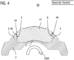
- FIG 4 shows a side view in section of a brake pad held in a brake carrier 2 according to the prior art, of which in the sectional view of the Figure 4 only the brake pad carrier plate (hereinafter also referred to as the pad carrier plate) 41 is visible.
- the brake carrier 2 is designed with respective inlet-side and outlet-side pad horns 3, 4 supporting the pad carrier plate 41.
- the pad horns 3 and 4 and the bridge part 7 connecting them form the pad shaft in which the brake pad is guided with play (see gap 42).
- the pad carrier plate 41 To install or remove the pad carrier plate 41, it is pushed vertically into the gap between the two pad horns 3, 4, with the pad horns 3, 4 extending to the radially outer edge or almost to the edge of the brake pad carrier plate 41. Both the inner surfaces 5, 6 of the pad horns 3, 4 and the support surfaces 46 of the pad carrier plate 41 adjacent to them are designed as flat surfaces.
- the carrier horn at the rear in a main direction of rotation HDR of the brake disc i.e. the direction of rotation of the brake disc when the motor vehicle is driving forward, is referred to as the inlet-side carrier horn 3.
- a gap 42 can also be seen between the inlet-side support surface 46 of the pad carrier plate 41 and the inlet-side pad horn 3, which causes the play and the impact noises described above. In order to avoid such effects, various solutions are known in the prior art.
- DE 10 2012 002 734 A1 It is proposed to arrange a spring element at the bottom of the pad shaft, which presses the brake pad radially against round guide surfaces.
- DE 10 2012 002 734 A1 The proposed design cannot be implemented with standard pad shafts and prevents normal insertion of the brake pads in the radial direction. In order to replace the pads, they must first be moved in the direction of the brake disc after the pressure pieces have been completely reset until they have completely left the pad shaft in this direction. Only then is removal in the radial direction possible. However, this means more work, especially if the brake pads are only to be checked and not replaced.
- the documents DE10 2010 019470 A1 and DE10 2012 006135 A1 disclose an elastic element between a brake carrier horn and a brake pad, wherein the elastic element lies in a recess of the brake pad.
- the object of the invention is in particular to provide a brake pad which can be used with conventional pad shaft designs, as in Figure 4 shown, works and/or can be installed in existing floating calliper brakes only as required.
- the design is intended to prevent the pad from impacting with a delay in at least one main direction of travel and at least not to cause damage to the structure in the other direction of travel, thus allowing safe braking.
- a brake pad for receiving in a pad slot of a disc brake and a brake pad holding device of a disc brake of a motor vehicle.
- the motor vehicle can be a commercial vehicle.
- the disc brake can be a floating caliper brake.
- the brake pad holding device comprises a brake carrier, preferably a brake carrier that is stationary on the vehicle side, having a pad shaft for receiving a brake pad.
- the pad shaft is delimited in relation to a main direction of rotation of the brake disc on the brake disc inlet side and the brake disc outlet side by a pad horn of the brake carrier.
- the brake pad holding device further comprises a brake pad guided in the pad shaft, having a pad holder and a friction pad attached thereto.
- the brake pad holding device further comprises a spring element, i.e. a resilient element that is supported on, i.e. rests against, a pad horn and a support surface of the pad holder adjacent to this pad horn.
- the pad horns and preferably the bridge part of the brake carrier connecting them form the pad shaft in which the brake pad is guided.
- the pad horn is also referred to as the carrier horn.
- the term “carrier horn” is used instead of the term “pad horn” within the scope of the present invention. Both terms are to be regarded as synonymous within the scope of the present invention.
- the pad horns are preferably each designed as a carrier with a straight support surface facing the brake pad, i.e. these support surfaces of the inlet-side and outlet-side pad horns are parallel.
- the pad holder is usually designed as a carrier plate and is also referred to as a pad carrier plate or pad back plate and can also have so-called underlayer intermediate layers.
- the top side of the friction pad serves as a friction surface for tribological interaction with a friction element, e.g. a brake disc.
- the carrier horn at the rear in the main direction of rotation of the brake disc i.e. the direction of rotation of the brake disc when the vehicle is moving forward
- the carrier horn at the front in the main direction of rotation of the brake disc i.e. the direction of rotation of the brake disc when the vehicle is moving forward
- the outlet-side carrier horn The carrier horn at the front in the main direction of rotation of the brake disc, i.e. the direction of rotation of the brake disc when the vehicle is moving forward.
- a brake pad device is further characterized in that the spring element is inserted in a recess in the pad holder.
- the spring element can be inserted in the recess in such a way that, when not under load, it protrudes beyond the edge of the recess and thus beyond the support surface of the brake pad adjacent to the pad flange.
- the recess can be designed as a pocket or as a groove.
- the groove can be a longitudinal groove.
- the spring element can be inserted in the groove in such a way that it can expand longitudinally in the groove when under load.
- the spring element offers the advantage that the pad holder is pressed against the corresponding pad horn of the brake carrier, which eliminates the play between the pad holder and the pad shaft. This prevents the brake pad from being delayed in at least one direction of travel and at least in the other direction of travel it does not lead to damage to the structure and thus allows safe braking.
- the arrangement of the spring element in the recess offers the particular advantage that the spring element cannot be compressed too much and therefore always works in the elastic range.
- the spring element is supported on the inlet-side pad horn.
- the spring element rests on the inlet-side pad horn and on the support surface of the pad horn adjacent to the inlet-side pad horn.
- the depth of the recess and the spring element can be designed in such a way that the spring element can be completely immersed in the recess when under load.
- the depth of the recess must be large enough and/or the spring element must be designed in such a way that the spring element can be compressed so far that it no longer protrudes from the recess. This means that even play as small as zero millimeters can be reliably eliminated.
- An implementation according to the invention provides that the spring element is supported on the pad holder at at least two places, e.g. two points, and is supported on the pad flange at only one place, e.g. only one point. This prevents over-determination and prevents the brake pad from jamming in the pad shaft.
- the spring element can advantageously be made from round material or from a material with an oval cross-section.
- the contact point for the lining shaft can be located in a curve of the spring element so that only point contact occurs.
- the spring element can be made from round steel, for example.
- the spring element can also be designed as a wire spring, which enables a cost-effective and space-saving implementation.
- the spring element is secured at one point, e.g. held or fixed, in such a way that it does not change its position when the brake pad is inserted into the pad shaft.
- the recess into which the spring element is inserted can have a depression at one point into which one end of the spring element is inserted and held there, e.g. in a form-fitting manner.
- This depression can run perpendicularly or diagonally to the bottom of the depression or perpendicularly or diagonally to the surface of the friction horn.
- the end of the spring element inserted into the depression has a corresponding curvature and/or a kink in order to be able to be inserted into the depression.
- the spring element can move freely in at least one direction in order to ensure the spring travel without tension.
- the width of the recess may not exceed 50% of the thickness of the pad holder.
- the point of contact of the spring element on the pad horn is eccentric to the simplified force support on the outlet side, i.e. eccentric to the average force support of the brake pad on the pad horn on the outlet side.
- This average force support is understood to mean the resulting friction force of the brake pad on the pad horn on the outlet side, which typically acts at the middle height of the pad horn and the brake pad.
- the contact point of the spring element on the pad horn is located radially at a larger radius than the resulting force support of the brake pad on the outlet-side pad horn, since the play here can be larger due to the installation.
- the contact point of the spring element on the pad horn is in the upper half, preferably in the upper third, of the pad horn.
- the upper half or upper third is the one that is closer to the outer edge of the brake disc.
- a defined torque is created on the brake pad around a Z-axis parallel to the axis of rotation of the brake disc, which generates a supporting force on the inlet side of the carrier horn and thus stabilizes the brake pad in the pad shaft.
- the brake pad holding device can further comprise, in a manner known per se, a brake caliper which engages over a brake disc and is mounted in a floating manner on the brake carrier.
- a brake pad for receiving in a pad shaft of a brake carrier, which is stationary on the vehicle side, of a brake pad holding device of a disc brake, wherein the pad shaft is delimited with respect to a main direction of rotation of the brake disc on the brake disc inlet side and the brake disc outlet side by a pad horn of the brake carrier.
- the recess can be a groove.
- the invention further relates to a motor vehicle, in particular a commercial vehicle, with a brake pad holding device as disclosed in this document.
- top, bottom, left, right, front, back, etc. refer exclusively to the exemplary representation and position of the disc brake, the pad carrier plate and the brake carrier chosen in the respective figures. These terms are not to be understood as restrictive, i.e. these references can change due to different working positions or the mirror-symmetrical design or the like.
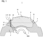
- Figure 1 shows a side view in section of a brake pad holding device according to an embodiment of the invention.
- a known brake carrier 2 of a disc brake for example a floating caliper brake
- the brake carrier 2 can be designed as a separate component, as shown here, or as an integral part of a brake caliper.
- To attach the brake carrier 2 to a vehicle axle it is usually provided with holes into which screws or bolts can be inserted and which hold the brake carrier to the vehicle axle.
- the reference number 11 designates a known pad carrier plate (also referred to as pad backing plate) of a brake pad 10, of which Figure 1 only the lining carrier plate 11 is visible and on which Figure 2 On the back side that cannot be seen is a friction lining 17 (visible in Figure 3 ).
- a thin groove 18 can be made in the friction lining 17 to absorb wear particles that arise on the friction surface during braking.
- the brake carrier 2 is designed with respective inlet-side and outlet-side lining horns 3, 4 that support the lining carrier plate 11.
- the lining horns 3 and 4 and the bridge part 7 connecting them form the lining shaft in which the brake lining 10 is guided.
- the carrier horn 3 represents the inlet-side pad horn 3, since it is the rear pad horn in the main direction of rotation HDR of the brake disc, i.e. the direction of rotation of the brake disc when the motor vehicle is moving forward.
- the pad horn 4 is accordingly the outlet-side pad horn.
- the pad horns 3, 4 are each designed as supports with a straight support surface 5, 6 facing the brake pad, i.e. these support surfaces 5, 6 of the inlet-side and outlet-side pad horns are parallel. Adjacent to these support surfaces 5, 6 are the pad horn support surfaces 19 of the pad carrier plate, i.e. the lateral outer surfaces of the pad carrier plate 11, with which the pad carrier plate 11 can be supported on the support surfaces 5, 6 of the pad horns 3, 4 when the pad carrier plate has been inserted into the pad shaft.
- a recess in the form of a groove 12 is made in one of the pad horn support surfaces 19 of the pad backing plate 11, into which a spring element 20, here a wire spring made of an annular steel, is inserted.
- the recess is made in the inlet-side pad horn support surface, whereby the pad backing plate 11 is pressed on the brake disc outlet side against the inlet-side pad horn 3 of the brake carrier 2.
- the spring element 20 can immerse itself completely in the groove 12 and thus eliminate play from zero millimeters. When the spring element is not compressed, the spring element protrudes from the groove 12 and thus protrudes beyond the groove walls 13.
- the resilient element (spring element) 20 is supported in the pad backing plate 11 at two points 22 and 23, i.e. the spring element 20 rests on the groove base 14 at the two points 22 and 23. In contrast, the spring element 20 is only in contact with the pad shaft or the inlet-side pad horn 3 at one point 21. This prevents the brake pad 10 from over-determining and jamming in the pad shaft.
- the contact point 21 on the pad shaft is located in a curve of the spring element 20 in order to reduce contact friction.
- the contact point 21 is advantageously located eccentrically for simplified force support on the outlet side and, in the embodiment shown, also radially on a larger radius, since the clearances can be larger here due to assembly.
- the resulting force vector of the averaged force support on the run-out side acts at point P, through which the dot-dashed horizontal line runs. Eccentric to this with the distance d from the resulting force vector of the averaged force support on the run-out side is the contact point 21 on the inlet-side pad flange 3. The point 21 is located above this force vector in relation to the resulting force vector of the averaged force support on the run-out side, i.e. radially on a larger radius and thus closer to the outer peripheral side of the brake disc (not shown).
- the spring element 20 is secured at at least one point in such a way that it does not change its position when the brake pad 10 is inserted into the pad shaft, and can move freely in at least one direction in order to ensure that the spring travel is free of tension.
- a recess 15 is made in a lower end region S of the groove 12, into which a hook-shaped, curved end 24 of the spring element is inserted to form a positive-locking holder.
Landscapes
- Engineering & Computer Science (AREA)
- General Engineering & Computer Science (AREA)
- Mechanical Engineering (AREA)
- Braking Arrangements (AREA)
Description
- Die vorliegende Erfindung betrifft einen Bremsbelag und eine Bremsbelaghaltevorrichtung einer Scheibenbremse eines Kraftfahrzeugs.
- Im Bereich der Radbremsen nimmt das Thema unerwünschter Geräuschentwicklung großen Raum ein. Neben reibungsinduzierten Schwingungen wie z. B. Quietschen treten aber auch andere Geräusche auf, die auf Fahrbahnunebenheiten oder Bremsbetätigungsvorgänge zurückgeführt werden können.
- Nach dem Stand der Technik kommen im Nutzfahrzeugbereich beispielsweise Schwimmsattelbremsen zum Einsatz. Um dabei die hohen auftretenden Bremsmomente abzustützen, werden die Bremsbeläge in einem achsfesten Bremsträger in beide Rotationsrichtungen der Bremsscheibe durch sogenannte Belaghörner abgestützt. Der schwimmend gelagerte Bremssattel erzeugt dann lediglich die Zuspannkraft, mit der die Bremsbeläge an die Bremsscheibe gedrückt werden. Damit die Bremsbeläge leichtgängig im Belagschacht bewegt werden können, werden Bremsbeläge und Bremsbelagschacht in einer bestimmten Toleranzlage zueinander bearbeitet. Die Belaghörner des Bremsträgers sind dabei im Normalzustand parallel zueinander gefertigt. Dadurch können unterschiedlich große Spiele entstehen. Bei einer manuellen Montage des Bremsträgers (z. B. nach einem Bremsscheibenwechsel) ist es jedoch möglich, dass sich durch das Schraubenanzugsmoment die Belagschachtform des Bremsträgers derart V-förmig verformt, dass das Spiel an der Spitze der Belaghörner sich weiter vergrößert. Im Fahrzeugbetrieb liegt der Bremsbelag abhängig von der Einbaulage des Bremssattels schwerkraftbedingt entweder am bremsscheibeneinlaufenden Belaghorn (sog. "9-Uhr-Einbaulage"), am bremsscheibenauslaufenden Belaghorn (sog. "3-Uhr-Einbaulage) oder undefiniert (sog. "12-Uhr-Einbaulage") an.
- Ein Bremsmoment kann jedoch erst dann abgestützt werden, wenn der Bremsbelag am bremsscheibenauslaufenden Belaghorn anliegt. Sollte der Bremsbelag nun schwerkraftbedingt am bremsscheibeneinlaufenden Horn anliegen, muss er erst das komplette Spiel, das sich durch die Fertigungstoleranzen und Bremsträgerverformung gebildet hat, überwinden. In dieser Zeit nimmt der Bremsbelag jedoch bedingt durch die Bremsscheibenrotation Geschwindigkeit auf, bevor er am auslaufseitigen Belaghorn anschlägt und Bremsmoment übertragen werden kann. Dies führt damit zu einem verzögerten Ansprechen der Bremse und einer ungewünschten Geräuschbildung. Beim Lösen der Bremse fällt der Bremsbelag dann wieder auf das einlaufseitige Belaghorn zurück, was wiederum in einem Anschlaggeräusch resultiert.
-
Figur 4 zeigt eine Seitendraufsicht im Schnitt auf einen in einem Bremsträger 2 gehaltenen Bremsbelag gemäß dem Stand der Technik, von dem in der Schnittansicht derFigur 4 nur die Bremsbelagträgerplatte (nachfolgend auch kurz als Belagträgerplatte bezeichnet) 41 sichtbar ist. Bei dieser bekannten Bremsbelaghaltevorrichtung 40 ist der Bremsträger 2 mit jeweiligen einlaufseitigen und auslaufseitigen die Belagträgerplatte 41 stützenden Belaghörnern 3, 4 ausgebildet. Die Belaghörner 3 und 4 und das diese verbindende Brückenteil 7 bilden den Belagschacht, in dem der Bremsbelag mit Spiel (siehe Spalt 42) geführt ist. - Zum Ein- oder Ausbau der Belagträgerplatte 41 wird diese senkrecht in die Lücke zwischen den beiden Belaghörnern 3, 4 eingeschoben, wobei die Belaghörner 3, 4 sich bis zum radial außen liegenden Rand oder nahezu bis zum Rand der Bremsbelagträgerplatte 41 erstrecken. Dabei sind sowohl die Innenflächen 5, 6 der Belaghörner 3, 4 als auch die diesen benachbarten Stützflächen 46 der Belagträgerplatte 41 als ebene Flächen ausgebildet. Als einlaufseitiges Trägerhorn 3 wird dabei das in einer Hauptdrehrichtung HDR der Bremsscheibe, also der Drehrichtung der Bremsscheibe während einer Vorwärtsfahrt des Kraftfahrzeugs, hintere Trägerhorn bezeichnet. Ferner erkennbar ist ein Spalt 42 zwischen der einlaufseitigen Stützfläche 46 der Belagträgerplatte 41 und dem einlaufseitigen Belaghorn 3 erkennbar, aufgrund dessen das Spiel und die vorstehend beschriebenen Anschlaggeräusche entstehen. Um derartige Effekte zu vermeiden, sind nach dem Stand der Technik verschiedene Lösungen bekannt.
- Aus dem Dokument
US 3,885,651 A ist bekannt, eine separate Belagschachtfeder zwischen Bremsbelag und Träger anzuordnen. Ein Nachteil hieran ist, dass die Belagschachtfeder bei einem Bremsvorgang in rückwärtiger Richtung derart komprimiert wird, dass eine plastische Verformung nicht ausgeschlossen werden kann. In diesem Fall wäre eine anschließende ordnungsgemäße Funktion der Belagschachtfeder nicht mehr gewährleistet. - In der Offenlegungsschrift
DE 10 2012 002 734 A1 wird dagegen vorgeschlagen, ein Federelement am Boden des Belagschachts anzuordnen, welches den Bremsbelag radial gegen runde Führungsflächen drückt. Die in derDE 10 2012 002 734 A1 vorgeschlagene Konstruktion lässt sich nicht mit Standardbelagschächten umsetzen und verhindert ein normales Einsetzen der Bremsbeläge in radialer Richtung. Um die Beläge zu tauschen, müssen diese nach einem vollständigen Zurückstellen der Druckstücke erst in Richtung Bremsscheibe bewegt werden, bis sie den Belagschacht in dieser Richtung vollständig verlassen haben. Erst dann ist ein Entfernen in radialer Richtung möglich. Dies bedeutet jedoch einen höheren Arbeitsaufwand, gerade wenn die Bremsbeläge nur kontrolliert, aber nicht getauscht werden sollen. - Die Dokumente
DE10 2010 019470 A1 undDE10 2012 006135 A1 offenbaren ein elastisches Element zwischen einem Bremsträgerhorn und einem Bremsbelag, wobei das elastische Element in einer Ausnehmung des Bremsbelages einliegt. - Es ist somit eine Aufgabe der Erfindung, eine verbesserte Bremsbelaghaltevorrichtung und einen verbesserten Bremsbelag einer Scheibenbremse bereitzustellen, mit denen Nachteile herkömmlicher Vorrichtungen vermieden werden können. Die Aufgabe der Erfindung ist es insbesondere, einen Bremsbelag bereitzustellen, der mit üblichen Belagschachtbauarten, wie in
Figur 4 dargestellt, funktioniert und/oder auch nur nach Bedarf in vorhandene Schwimmsattelbremsen eingebracht werden kann. Die Konstruktion soll dabei verhindern, dass der Belag in zumindest einer Hauptfahrrichtung verzögert anschlägt und wenigstens in der anderen Fahrtrichtung nicht zu einer Beschädigung der Konstruktion führt und somit ein sicheres Bremsen erlaubt. - Diese Aufgaben werden durch Vorrichtungen mit den Merkmalen der unabhängigen Ansprüche gelöst. Vorteilhafte Ausführungsformen und Anwendungen der Erfindung ergeben sich aus den abhängigen Ansprüchen und werden in der folgenden Beschreibung unter teilweiser Bezugnahme auf die Figuren näher erläutert.
- Gemäß allgemeinen Gesichtspunkten der Erfindung wird ein Bremsbelag zur Aufnahme in einen Belagschacht einer Scheibenbremse sowie eine Bremsbelaghaltevorrichtung einer Scheibenbremse eines Kraftfahrzeugs bereitgestellt. Das Kraftfahrzeug kann ein Nutzfahrzeug sein. Die Scheibenbremse kann eine Schwimmsattelbremse sein.
- Die Bremsbelaghaltevorrichtung umfasst einen Bremsträger, vorzugsweise einen fahrzeugseitig ortsfesten Bremsträger, aufweisend einen Belagschacht zur Aufnahme eines Bremsbelags. Der Belagschacht ist in Bezug auf eine Hauptdrehrichtung der Bremsscheibe bremsscheibeneinlaufseitig und bremsscheibenauslaufseitig jeweils durch ein Belaghorn des Bremsträgers begrenzt.
- Die Bremsbelaghaltevorrichtung umfasst ferner einen in dem Belagschacht geführten Bremsbelag, aufweisend einen Belaghalter und einen daran befestigten Reibbelag. Die Bremsbelaghaltevorrichtung umfasst ferner ein Federelement, d. h. ein federndes Element, das sich an einem Belaghorn und einer diesem Belaghorn benachbarten Stützfläche des Belaghalters abstützt, d. h. anliegt.
- Die Belaghörner und vorzugsweise das diese verbindende Brückenteil des Bremsträgers bilden den Belagschacht, in dem der Bremsbelag geführt ist. Das Belaghorn wird auch als Trägerhorn bezeichnet. Gegebenenfalls wird im Rahmen der vorliegenden Erfindung statt des Begriffs "Belaghorn" daher auch der Begriff "Trägerhorn" verwendet. Beide Begriffe sind im Rahmen der vorliegenden Erfindung als gleichbedeutend anzusehen. Die Belaghörner sind vorzugsweise jeweils als Träger mit einer dem Bremsbelag zugewandten geradlinigen Stützfläche ausgebildet, d. h., diese Stützflächen der einlaufseitigen und auslaufseitigen Belaghorns sind parallel.
- Der Belaghalter ist üblicherweise als Trägerplatte ausgeführt und wird auch als Belagträgerplatte oder Belagrückenplatte bezeichnet und kann ferner sog. Underlayer-Zwischenschichten aufweisen. Die Belagoberseite des Reibbelags dient als Reibfläche zum tribologischen Zusammenwirken mit einem Reibelement, z. B. einer Bremsscheibe.
- Als einlaufseitiges Trägerhorn wird dabei das in einer Hauptdrehrichtung der Bremsscheibe, also der Drehrichtung der Bremsscheibe während einer Vorwärtsfahrt des Kraftfahrzeugs, hintere Trägerhorn bezeichnet. Entsprechend wird als auslaufseitiges Trägerhorn das in einer Hauptdrehrichtung der Bremsscheibe, also der Drehrichtung der Bremsscheibe während einer Vorwärtsfahrt des Kraftfahrzeugs, vordere Trägerhorn bezeichnet.
- Eine erfindungsgemäße Bremsbelagvorrichtung zeichnet sich ferner dadurch aus, dass das Federelement in einer Ausnehmung des Belaghalters eingelegt ist. Das Federelement kann so in die Ausnehmung eingelegt sein, dass es im nicht belasteten Zustand über den Rand der Ausnehmung und somit über die dem Belaghorn benachbarte Stützfläche des Bremsbelags übersteht. Die Ausnehmung kann als Tasche oder als Nut ausgeführt sein. Die Nut kann eine Längsnut sein. Das Federelement kann so in die Nut eingelegt ist, dass es sich in der Nut bei Belastung längs ausdehnen kann.
- Das Federelement bietet den Vorteil, dass dadurch der Belaghalter an das entsprechende Belaghorn des Bremsträgers gedrückt wird, wodurch das Spiel zwischen Belaghalter und Belagschacht eliminiert wird. Hierdurch wird verhindert, dass der Bremsbelag in zumindest einer Fahrrichtung verzögert anschlägt und wenigstens in der anderen Fahrtrichtung nicht zu einer Beschädigung der Konstruktion führt und somit ein sicheres Bremsen erlaubt. Die Anordnung des Federelements in der Ausnehmung bietet den besonderen Vorzug, dass das Federelement nicht zu stark zusammengedrückt werden kann und somit stets im elastischen Bereich arbeitet.
- Erfindungsgemäß stützt sich das Federelement am einlaufseitigen Belaghorn ab. Mit anderen Worten liegt das Federelement am einlaufseitigen Belaghorn und an der dem einlaufseitigen Belaghorn benachbarten Stützfläche des Belaghorns an. Diese Anordnung stellt sicher, da der Bremsbelag bei einem Bremsvorgang in der Hauptfahrrichtung, d. h. während einer Vorwärtsfahrt des Kraftfahrzeugs, nicht verzögert anschlägt, dass der Bremsbelag durch die Federkraft des Federelements bereits am bremsscheibenauslaufenden Belaghorn anliegt und sich dort abstützt.
- Gemäß einem weiteren Aspekt können die Tiefe der Ausnehmung und das Federelement so ausgeführt sein, dass das Federelement im belasteten Zustand vollständig in die Ausnehmung eintauchen kann. Hierzu muss die Tiefe der Ausnehmung so groß sein und/oder das Federelement so ausgeführt sein, dass das Federelement so weit zusammengedrückt werden kann, dass es nicht mehr aus der Ausnehmung herausragt. Dadurch können auch Spiele ab null Millimeter zuverlässig eliminiert werden.
- Eine erfindungsgemäße Realisierung sieht vor, dass sich das Federelement an dem Belaghalter an mindestens zwei Stellen, z. B. zwei Punkten, abstützt und sich am Belaghorn an nur einer Stelle, z. B. an nur einem Punkt, abstützt. Dadurch wird eine Überbestimmung vermieden und ein Klemmen des Bremsbelags im Belagschacht vermieden.
- Um die Reibung in Zuspannrichtung weiterhin zu reduzieren, kann das federnde Element in vorteilhafter Weise aus Rundmaterial oder aus einem Material mit einem ovalen Querschnitt gefertigt sein. Hierbei kann der Anlagepunkt zum Belagschacht sich in einer Rundung des Federelements befinden, so dass nur ein Punktkontakt zustande kommt. Das Federelement kann beispielsweise aus einem Rundstahl gefertigt sein. Ferner kann das Federelement als eine Drahtfeder ausgeführt sein, was eine kostengünstige und platzsparende Realisierung ermöglicht.
- Eine weitere vorteilhafte Möglichkeit der erfindungsgemäßen Realisierung sieht vor, dass das Federelement an einem Punkt derart gesichert ist, z. B. gehaltert oder fixiert ist, dass es bei Einschub des Bremsbelags in den Belagschacht nicht seine Lage ändert. Beispielsweise kann die Ausnehmung, in die das Federelement eingelegt ist, an einer Stelle eine Vertiefung aufweisen, in der ein Ende des Federelements eingesteckt ist und dort z. B. formschlüssig gehaltert ist. Diese Vertiefung kann senkrecht oder schräg zum Boden der Vertiefung verlaufen bzw. senkrecht oder schräg zur Oberfläche des Reibhorns. Das in die Vertiefung gesteckte Ende des Federelements weist eine entsprechende Krümmung und/oder einen Knick auf, um in die Vertiefung gesteckt werden zu können.
- Gemäß einem weiteren Aspekt kann sich das Federelement in mindestens eine Richtung frei bewegen, um den Federweg verspannungsfrei gewährleisten zu können.
- Um die Festigkeit der Belaghalters zu gewährleisten, kann eine Breite der Ausnehmung höchstens 50 % der Dicke des Belaghalters aufweisen.
- Vorstehend wurde bereits erwähnt, dass es vorteilhaft ist, wenn das Federelement am Belaghorn an nur einer Stelle anliegt und sich damit an nur einer Stelle abstützt. Bei einer vorteilhaften Variante dieser Ausgestaltungsform ist der Anlagepunkt des Federelements am Belaghorn, vorzugsweise am einlaufseitigen Belaghorn, exzentrisch zur vereinfachten Kraftabstützung auf der Auslaufseite, d. h. exzentrisch zur gemittelten Kraftabstützung des Bremsbelags an dem auslaufseitigen Belaghorn. Unter dieser gemittelten Kraftabstützung wird die resultierende Reibkraft des Bremsbelags an dem auslaufseitigen Belaghorn verstanden, die typischerweise auf mittlerer Höhe des Belaghorns und des Bremsbelags angreift.
- Dadurch ergibt sich am Bremsbelag ein definiertes Drehmoment um eine zur Drehachse der Bremsscheibe parallele Z-Achse, das einem auf den Bremsbelag bei Bremsen wirkenden Drehmoment entgegenwirkt, welches versucht, den Bremsbelag aus dem Belagschacht herauszudrehen.
- Erfindungsgemäß befindet sich der der Anlagepunkt des Federelements am Belaghorn radial an einem größeren Radius als die resultierende Kraftabstützung des Bremsbelags an dem auslaufseitigen Belaghorn, da hier die Spiele montagebedingt größer sein können. Mit anderen Worten liegt der der Anlagepunkt des Federelements am Belaghorn in der oberen Hälfte, vorzugsweise im oberen Drittel, des Belaghorns. Die obere Hälfte bzw. das obere Drittel ist dasjenige, das näher an dem äußeren Rand der Bremsscheibe liegt.
- Gemäß dieser Variante ergibt sich am Bremsbelag ein definiertes Drehmoment um eine zur Drehachse der Bremsscheibe parallele Z-Achse, das einlaufseitig am Trägerhorn eine Abstützkraft erzeugt und den Bremsbelag somit im Belagschacht stabilisiert.
- Gemäß einem weiteren Aspekt der Erfindung kann die Bremsbelaghaltevorrichtung ferner in an sich bekannter Weise einen eine Bremsscheibe übergreifenden Bremssattel, der schwimmend am Bremsträger gelagert ist, aufweisen.
- Ferner beansprucht die Erfindung einen Bremsbelag nach Anspruch 9. Gemäß einem weiteren Gesichtspunkt der Erfindung wird somit ein Bremsbelag bereitgestellt, insbesondere ein Bremsbelag zur Aufnahme in einen Belagschacht eines fahrzeugseitig ortsfesten Bremsträgers einer Bremsbelaghaltevorrichtung einer Scheibenbremse, wobei der Belagschacht in Bezug auf eine Hauptdrehrichtung der Bremsscheibe bremsscheibeneinlaufseitig und bremsscheibenauslaufseitig jeweils durch ein Belaghorn des Bremsträgers begrenzt wird.
- Wie vorstehend bereits erwähnt, kann die Ausnehmung eine Nut sein.
- Zur Vermeidung von weiteren Wiederholungen sollen alle in Zusammenhang mit der Bremsbelagvorrichtung offenbarten Merkmale des Bremsbelags auch als für einen Vorrichtungsanspruch auf den Bremsbelag per se offenbart gelten und beanspruchbar sein.
- Die Erfindung betrifft ferner ein Kraftfahrzeug, insbesondere ein Nutzfahrzeug, mit einer Bremsbelaghaltevorrichtung, wie in diesem Dokument offenbart.
- Die zuvor beschriebenen bevorzugten Ausführungsformen und Merkmale der Erfindung sind beliebig miteinander kombinierbar. Weitere Einzelheiten und Vorteile der Erfindung werden im Folgenden unter Bezug auf die beigefügten Zeichnungen beschrieben. Es zeigen:
- Figur 1
- eine Seitendraufsicht im Schnitt einer Bremsbelaghaltevorrichtung gemäß einer Ausführungsform der Erfindung;
- Figur 2
- eine Seitendraufsicht im Schnitt eines Bremsbelaghalters mit Federelement gemäß einem Ausführungsbeispiel der Erfindung; und
- Figur 3
- eine perspektivische Ansicht des Bremsbelaghalters aus
Figur 2 ; und - Figur 4
- eine Seitendraufsicht im Schnitt einer aus dem Stand der Technik bekannten Bremsbelaghaltevorrichtung.
- In der nachfolgenden Figurenbeschreibung beziehen sich Begriffe wie oben, unten, links, rechts, vorne, hinten usw. ausschließlich auf die in den jeweiligen Figuren gewählte beispielhafte Darstellung und Position der Scheibenbremse, der Belagträgerplatte und des Bremsträgers. Diese Begriffe sind nicht einschränkend zu verstehen, d. h., durch verschiedene Arbeitsstellungen oder die spiegelsymmetrische Auslegung oder dergleichen können sich diese Bezüge ändern.
-
Figur 1 zeigt eine Seitendraufsicht im Schnitt einer Bremsbelaghaltevorrichtung gemäß einer Ausführungsform der Erfindung. In derFigur 1 ist dabei ein an sich bekannter Bremsträger 2 einer Scheibenbremse, beispielsweise einer Schwimmsattelbremse, gezeigt. Der Bremsträger 2 kann dabei als separates Bauteil, wie hier gezeigt, oder als integraler Bestandteil eines Bremssattels ausgebildet sein. Zur Befestigung des Bremsträgers 2 an einer Fahrzeugachse ist dieser üblicherweise mit Bohrungen versehen, in die Schrauben oder Bolzen einführbar sind und den Bremsträger an der Fahrzeugachse halten. - Mit dem Bezugszeichen 11 ist dabei eine an sich bekannte Belagträgerplatte (auch als Belagrückenplatte bezeichnet) eines Bremsbelags 10 bezeichnet, von dem in
Figur 1 nur die Belagträgerplatte 11 sichtbar ist und auf dessen inFigur 2 nicht zu sehender Rückseite ein Reibbelag 17 (zu erkennen inFigur 3 ) festgelegt ist. Zur Aufnahme von im Bremsbetrieb an der Reibfläche entstehenden Abriebpartikeln kann in den Reibbelag 17 eine dünne Nut 18 eingebracht sein. Der Bremsträger 2 ist mit jeweiligen einlaufseitigen und auslaufseitigen die Belagträgerplatte 11 stützenden Belaghörnern 3, 4 ausgebildet. Die Belaghörner 3 und 4 und das diese verbindende Brückenteil 7 bilden den Belagschacht, in dem der Bremsbelag 10 geführt ist. - Das Trägerhorn 3 stellt vorliegend das einlaufseitige Belaghorn 3 da, da es in der Hauptdrehrichtung HDR der Bremsscheibe, also der Drehrichtung der Bremsscheibe während einer Vorwärtsfahrt des Kraftfahrzeugs, das hintere Belaghorn ist. Das Belaghorn 4 ist entsprechend das auslaufseitige Belaghorn. Die Belaghörner 3, 4 sind jeweils als Träger mit einer dem Bremsbelag zugewandten geradlinigen Stützfläche 5, 6 ausgebildet, d. h., diese Stützflächen 5, 6 des einlaufseitigen und auslaufseitigen Belaghorns sind parallel. Zu diesen Stützflächen 5, 6 benachbart sind die Belaghornabstützflächen 19 der Belagträgerplatte, d. h. die seitlichen Außenflächen der Belagträgerplatte 11, mit denen sich die Belagträgerplatte 11 an den Stützflächen 5, 6 der Belaghörner 3, 4 abstützen kann, wenn die Belagträgerplatte in den Belagschacht eingebracht wurde.
- In die Belagrückenplatte 11 ist in eine der Belaghornabstützflächen 19 eine Ausnehmung in Form einer Nut 12 eingebracht, in die ein federndes Element 20, hier eine Drahtfeder aus einem Ringstahl, eingebracht ist. Die Ausnehmung ist in die einlaufseitige Belaghornabstützfläche eingebracht, wodurch die Belagrückenplatte 11 bremsscheibenauslaufseitig an das einlaufseitige Belaghorn 3 des Bremsträgers 2 gedrückt wird. Das Federelement 20 kann dabei voll in die Nut 12 eintauchen und damit Spiele ab null Millimeter eliminieren. Im nicht komprimierten Zustand des Federelements ragt das Federelement aus der Nut 12 heraus und überragt damit die Nutwände 13.
- Das federnde Element (Federelement) 20 stützt sich dabei in der Belagrückenplatte 11 an zwei Punkten 22 und 23 ab, d. h., das Federelement 20 liegt an den zwei Punkten 22 und 23 am Nutboden 14 auf. Dagegen steht das Federelement 20 nur an einem Punkt 21 mit dem Belagschacht bzw. dem einlaufseitigen Belaghorn 3 in Berührung. Dadurch werden eine Überbestimmung und ein Klemmen des Bremsbelags 10 im Belagschacht vermieden. Hierbei befindet sich der Anlagepunkt 21 am Belagschacht in einer Rundung des Federelements 20, um eine Kontaktreibung zu reduzieren.
- Darüber hinaus befindet sich der Anlagepunkt 21 vorteilhafterweise exzentrisch zur vereinfachten Kraftabstützung auf der Auslaufseite und in dem gezeigten Ausführungsbeispiel ferner radial an einem größeren Radius, da hier die Spiele montagebedingt größer sein können.
- Dies ist in
Figur 2 besser erkennbar, die eine vergrößerte Seitendraufsicht im Schnitt des Bremsbelaghalters 10 mit Federelement 20 ausFigur 1 zeigt. - Der resultierende Kraftvektor der gemittelten Kraftabstützung auf der Auslaufseite greift am Punkt P an, durch den die punktgestrichelte horizontale Linie verläuft. Exzentrisch hierzu mit dem Abstand d von dem resultierenden Kraftvektor der gemittelten Kraftabstützung auf der Auslaufseite liegt der Anlagepunkt 21 am einlaufseitigen Belaghorn 3. Der Punkt 21 liegt in Bezug auf den resultierenden Kraftvektor der gemittelten Kraftabstützung auf der Auslaufseite oberhalb dieses Kraftvektors, d. h. radial an einem größeren Radius und damit näher an der Außenumfangsseite der Bremsscheibe (nicht gezeigt).
- Das Federelement 20 ist dabei an mindestens einem Punkt derart gesichert, dass es bei Einschub des Bremsbelags 10 in den Belagschacht nicht seine Lage ändert, und kann sich in mindestens einer Richtung frei bewegen, um den Federweg verspannungsfrei zu gewährleisten. Hierzu ist vorliegend eine Vertiefung 15 in einem unteren Endbereich S der Nut 12 eingebracht, in die ein hakenförmig gekrümmtes Ende 24 des Federelements zur Ausbildung einer formschlüssigen Halterung eingesteckt ist.
-
- 1
- Bremsbelaghaltevorrichtung
- 2
- Bremsträger
- 3
- Einlaufseitiges Belaghorn
- 4
- Auslaufseitiges Belaghorn
- 5
- Stützfläche des einlaufseitigen Belaghorns
- 6
- Stützfläche des auslaufseitigen Belaghorns
- 7
- Brückenteil
- 10
- Bremsbelag
- 11
- Belaghalter, z. B. Belagträgerplatte
- 12
- Ausnehmung, z. B. Nut
- 13
- Nutwand
- 14
- Nutboden
- 15
- Vertiefung
- 17
- Reibbelag
- 18
- Nut
- 19
- Stützfläche des Belaghalters (Belaghornabstützfläche)
- 20
- Federelement, z. B. Drahtfeder
- 21
- Abstützstelle am Belaghorn
- 22, 23
- Abstützstelle am Belaghalter
- 24
- Gekrümmtes Ende des Federelements
- 40
- Bremsbelaghaltevorrichtung
- 41
- Belaghalter, z. B. Belagträgerplatte
- 42
- Spiel
- 46
- Abstützfläche
- HDR
- Hauptdrehrichtung
- P
- Auslaufseitige gemittelte Kraftabstützstelle
- S
- Sicherungsstelle
Claims (12)
- Bremsbelaghaltevorrichtung (1) einer Scheibenbremse für eine Kraftfahrzeug, insbesondere eines Nutzfahrzeugs, aufweisend- einen Bremsträger (2), aufweisend einen Belagschacht zur Aufnahme eines Bremsbelags, wobei der Belagschacht in Bezug auf eine Hauptdrehrichtung (HDR) der Bremsscheibe bremsscheibeneinlaufseitig und bremsscheibenauslaufseitig jeweils durch ein Belaghorn (3, 4) des Bremsträgers (2) begrenzt wird;- einen in dem Belagschacht geführten Bremsbelag (10), aufweisend einen Belaghalter (11) und einen daran befestigten Reibbelag (17);- ein Federelement (20), das in einer Ausnehmung (12) des Belaghalters (11) eingelegt ist und das sich an einem Belaghorn (3) und einer diesem Belaghorn (3) benachbarten Stützfläche (19) des Belaghalters (11) abstützt,dadurch gekennzeichnet, dass sich das Federelement (20) an dem Belaghalter (11) an mindestens zwei Stellen (22, 23) abstützt und sich am Belaghorn (3) an nur einer Stelle (21) abstützt, wobei die Anlagestelle (21) des Federelements am einlaufseitigen Belaghorn (3) in der oberen Hälfte, vorzugsweise im oberen Drittel, des Belaghorns (3) liegt.
- Bremsbelaghaltevorrichtung (1) nach Anspruch 1, dadurch gekennzeichnet, dass eine Tiefe der Ausnehmung (12) und das Federelement (20) so ausgeführt sind, dass das Federelement (20) im belasteten Zustand vollständig in die Ausnehmung (12) eintauchen kann.
- Bremsbelaghaltevorrichtung (1) nach einem der vorhergehenden Ansprüche, dadurch gekennzeichnet, dass die Ausnehmung eine Nut (12), insbesondere eine Längsnut, ist.
- Bremsbelaghaltevorrichtung (1) nach einem der vorhergehenden Ansprüche, dadurch gekennzeichnet, dass das Federelement (20) aus einem Rundmaterial oder aus einem Material mit einem ovalem Querschnitt gefertigt ist.
- Bremsbelaghaltevorrichtung (1) nach einem der vorhergehenden Ansprüche, dadurch gekennzeichnet,a) dass das Federelement (20) an einer Stelle (S) derart gesichert ist, dass es bei Einschub des Bremsbelags (10) in den Belagschacht nicht seine Lage ändert; und/oderb) dass die Ausnehmung (12) an einer Stelle (S) eine Vertiefung aufweist, in die ein Ende (24) des Federelements (20) eingesteckt ist und/oder formschlüssig gesichert ist.
- Bremsbelaghaltevorrichtung (1) nach einem der vorhergehenden Ansprüche, dadurch gekennzeichnet, dass eine Breite der Ausnehmung (12) höchstens 50 % der Dicke des Belaghalters (11) aufweist.
- Bremsbelaghaltevorrichtung (1) nach einem der vorhergehenden Ansprüche, dadurch gekennzeichnet, dass die Anlagestelle (21) des Federelements am einlaufseitigen Belaghorn (3) exzentrisch zur gemittelten Kraftabstützung (Reibkraft) des Bremsbelags an dem auslaufseitigen Belaghorn (4) ist;
- Bremsbelaghaltevorrichtung (1) nach einem der vorhergehenden Ansprüche, gekennzeichnet durch einen eine Bremsscheibe übergreifenden Bremssattel, der schwimmend am Bremsträger (2) gelagert ist.
- Bremsbelag (10) zur Aufnahme in einen Belagschacht eines fahrzeugseitig ortsfesten Bremsträgers (2) einer Bremsbelaghaltevorrichtung (1) einer Scheibenbremse, wobei insbesondere der Belagschacht in Bezug auf eine Hauptdrehrichtung (HDR) der Bremsscheibe bremsscheibeneinlaufseitig und bremsscheibenauslaufseitig jeweils durch ein Belaghorn (3, 4) des Bremsträgers (2) begrenzt wird; aufweisend- einen Belaghalter (11) und- einen daran befestigten Reibbelag (17), wobei eine Belaghornabstützfläche (19) des Belaghalters (11) eine Ausnehmung (12) zur Aufnahme eines Federelements aufweist,ferner umfassend ein in die Ausnehmung eingelegtes Federelement (20), dadurch gekennzeichnet, dass eine Breite der Ausnehmung (12) höchstens 50 % der Dicke des Belaghalters (11) aufweist, und
die Ausnehmung (12) an einer Stelle (S) eine Vertiefung aufweist, in die ein Ende (24) des Federelements (20) eingesteckt ist, wobei das in die Vertiefung gesteckte Ende (24) des Federelements (20) einen Knick aufweist. - Bremsbelag nach Anspruch 9, wobei die Ausnehmung (12) eine Nut ist.
- Bremsbelag nach Anspruch 9 oder 10, wobei eine Tiefe der Ausnehmung (12) und das Federelement (20) so ausgeführt sind, dass das Federelement (20) im belasteten Zustand vollständig in die Ausnehmung (12) eintauchen kann, und/oder wobei das Federelement (20) aus einem Rundmaterial oder aus einem Material mit einem ovalen Querschnitt gefertigt ist.
- Kraftfahrzeug, insbesondere Nutzfahrzeugs, mit einer Bremsbelaghaltevorrichtung nach einem der vorhergehenden Ansprüche 1 bis 8.
Applications Claiming Priority (1)
| Application Number | Priority Date | Filing Date | Title |
|---|---|---|---|
| DE102016001321.4A DE102016001321A1 (de) | 2016-02-05 | 2016-02-05 | Bremsbelag und Bremsbelaghaltevorrichtung einer Scheibenbremse |
Publications (3)
| Publication Number | Publication Date |
|---|---|
| EP3203102A1 EP3203102A1 (de) | 2017-08-09 |
| EP3203102B1 EP3203102B1 (de) | 2021-07-28 |
| EP3203102B2 true EP3203102B2 (de) | 2025-01-15 |
Family
ID=57799623
Family Applications (1)
| Application Number | Title | Priority Date | Filing Date |
|---|---|---|---|
| EP17151576.0A Active EP3203102B2 (de) | 2016-02-05 | 2017-01-16 | Bremsbelag und bremsbelaghaltevorrichtung einer scheibenbremse |
Country Status (5)
| Country | Link |
|---|---|
| US (1) | US10082186B2 (de) |
| EP (1) | EP3203102B2 (de) |
| CN (1) | CN107061562A (de) |
| DE (1) | DE102016001321A1 (de) |
| RU (1) | RU2017103304A (de) |
Families Citing this family (8)
| Publication number | Priority date | Publication date | Assignee | Title |
|---|---|---|---|---|
| ITUB20159203A1 (it) * | 2015-12-23 | 2017-06-23 | Freni Brembo Spa | Assieme di pastiglia per pinza freno |
| GB2563081A (en) * | 2017-06-02 | 2018-12-05 | Meritor Heavy Vehicle Braking Systems Uk Ltd | A brake pad |
| GB2563079A (en) | 2017-06-02 | 2018-12-05 | Meritor Heavy Vehicle Braking Systems Uk Ltd | A disc brake |
| GB2566335A (en) * | 2017-09-12 | 2019-03-13 | Meritor Heavy Vehicle Braking Systems Uk Ltd | A disc brake |
| EP3584462B1 (de) * | 2018-06-20 | 2020-05-20 | WABCO Europe BVBA | Belagträger für eine scheibenbremse |
| CN108626277A (zh) * | 2018-07-01 | 2018-10-09 | 德清县海昌汽车零配件有限公司 | 一种汽车用制动器衬片 |
| DE102018118514A1 (de) * | 2018-07-31 | 2020-02-06 | Knorr-Bremse Systeme für Schienenfahrzeuge GmbH | Bremsbelaghalterung und Werkzeug für ein Schienenfahrzeug |
| CN114060438B (zh) * | 2021-11-16 | 2024-04-02 | 浙江杭亚新材料有限公司 | 一种用于盘式制动器的制动衬片保持装置 |
Citations (1)
| Publication number | Priority date | Publication date | Assignee | Title |
|---|---|---|---|---|
| DE102012006094A1 (de) † | 2012-03-26 | 2013-09-26 | Knorr-Bremse Systeme für Nutzfahrzeuge GmbH | Bremsbelaganordnung für eine Schiebesattel-Scheibenbremse |
Family Cites Families (16)
| Publication number | Priority date | Publication date | Assignee | Title |
|---|---|---|---|---|
| FR2046600A5 (de) * | 1970-05-05 | 1971-03-05 | Dba | |
| DE2204047A1 (de) * | 1972-01-28 | 1973-08-09 | Teves Gmbh Alfred | Bremsbacke fuer teilbelagscheibenbremsen |
| US3885651A (en) | 1973-04-30 | 1975-05-27 | Ferodo Sa | Brake assembly |
| DE3139942A1 (de) * | 1981-10-08 | 1983-04-28 | Alfred Teves Gmbh, 6000 Frankfurt | Bremsbackenanordnung |
| DE8327272U1 (de) * | 1983-09-22 | 1984-01-19 | Lucas Industries P.L.C., Birmingham, West Midlands | Selbsttaetig rueckstellbare bremsbacke fuer teilbelag-scheibenbremsen |
| GB8809966D0 (en) * | 1988-04-27 | 1988-06-02 | Lucas Ind Plc | Improvements relating to friction pad assemblies |
| DE10133579A1 (de) * | 2001-07-11 | 2003-01-30 | Federal Mogul Friction Product | Scheibenbremse mit integriertem Bremsbelag |
| JP4492271B2 (ja) * | 2004-09-22 | 2010-06-30 | 株式会社アドヴィックス | パッド吊下げ型のディスクブレーキ |
| DE102004053026B4 (de) * | 2004-11-03 | 2007-07-05 | Knorr-Bremse Systeme für Nutzfahrzeuge GmbH | Belagträgerplatte einer Scheibenbremse |
| DE102007049981B4 (de) * | 2007-10-18 | 2009-07-30 | Knorr-Bremse Systeme für Nutzfahrzeuge GmbH | Bremsbelag einer Scheibenbremse |
| DE102010019470B4 (de) * | 2010-05-05 | 2016-05-19 | Knorr-Bremse Systeme für Nutzfahrzeuge GmbH | Scheibenbremse für ein Nutzfahrzeug sowie Bremsbelag für eine Scheibenbremse |
| DE102011115214A1 (de) * | 2011-09-28 | 2013-03-28 | Knorr-Bremse Systeme für Nutzfahrzeuge GmbH | Scheibenbremse, insbesondere für ein Nutzfahrzeug, sowie Bremsbelag für eine Scheibenbremse |
| DE102012002734A1 (de) | 2012-02-10 | 2013-08-14 | Knorr-Bremse Systeme für Nutzfahrzeuge GmbH | Belaghaltesystem einer Scheibenbremse eines Kraftfahrzeugs |
| DE102012006082A1 (de) * | 2012-03-26 | 2013-09-26 | Knorr-Bremse Systeme für Nutzfahrzeuge GmbH | Scheibenbremse mit Rückstelleinrichtung und entsprechender Bremsbelag |
| DE102012006135A1 (de) * | 2012-03-26 | 2013-09-26 | Knorr-Bremse Systeme für Nutzfahrzeuge GmbH | Scheibenbremse für ein Nutzfahrzeug und Bremsbelag für eine Scheibenbremse |
| DE102012024945A1 (de) * | 2012-12-19 | 2014-06-26 | Lucas Automotive Gmbh | Scheibenbremse für ein Kraftfahrzeug und Bremsbelaganordnung mit rückstellender Federanordnung hierfür |
-
2016
- 2016-02-05 DE DE102016001321.4A patent/DE102016001321A1/de active Pending
-
2017
- 2017-01-16 EP EP17151576.0A patent/EP3203102B2/de active Active
- 2017-01-23 CN CN201710057172.6A patent/CN107061562A/zh active Pending
- 2017-02-01 RU RU2017103304A patent/RU2017103304A/ru not_active Application Discontinuation
- 2017-02-03 US US15/424,391 patent/US10082186B2/en active Active
Patent Citations (1)
| Publication number | Priority date | Publication date | Assignee | Title |
|---|---|---|---|---|
| DE102012006094A1 (de) † | 2012-03-26 | 2013-09-26 | Knorr-Bremse Systeme für Nutzfahrzeuge GmbH | Bremsbelaganordnung für eine Schiebesattel-Scheibenbremse |
Also Published As
| Publication number | Publication date |
|---|---|
| US10082186B2 (en) | 2018-09-25 |
| DE102016001321A1 (de) | 2017-08-10 |
| US20170227076A1 (en) | 2017-08-10 |
| EP3203102B1 (de) | 2021-07-28 |
| EP3203102A1 (de) | 2017-08-09 |
| RU2017103304A (ru) | 2018-08-02 |
| CN107061562A (zh) | 2017-08-18 |
Similar Documents
| Publication | Publication Date | Title |
|---|---|---|
| EP3203102B2 (de) | Bremsbelag und bremsbelaghaltevorrichtung einer scheibenbremse | |
| EP3359843B1 (de) | Scheibenbremse für ein nutzfahrzeug | |
| EP2812595B1 (de) | Belaghaltesystem einer scheibenbremse eines kraftfahrzeugs | |
| EP2923105B1 (de) | Scheibenbremse eines kraftfahrzeugs | |
| EP3516255B1 (de) | Scheibenbremse für ein nutzfahrzeug und bremsbelagsatz | |
| EP3149353B2 (de) | Scheibenbremse, bremssattel und bremsbelagsatz für eine scheibenbremse | |
| EP3194804B1 (de) | Scheibenbremse für ein nutzfahrzeug | |
| DE102017129672B4 (de) | Scheibenbremse für ein Nutzfahrzeug und Bremsbelagsatz | |
| DE102016120481A1 (de) | Scheibenbremse für ein Nutzfahrzeug und Bremsbelagsatz | |
| EP3033538A1 (de) | Belaghaltefeder eines bremsbelags und bremsbelaghalterung für eine scheibenbremse eines kraftfahrzeugs | |
| DE102011118313B4 (de) | Scheibenbremse, insbesondere für nutzfahrzeuge, sowie bremsbelag und druckplatte als separate bauteile für eine solche scheibenbremse | |
| DE102014113617B4 (de) | Bremsbelaghalterung einer Scheibenbremse und Scheibenbremse | |
| EP3027926B1 (de) | Scheibenbremse, insbesondere für nutzfahrzeuge, sowie bremsbelag einer solchen scheibenbremse | |
| EP3596354B1 (de) | Bremsträger und scheibenbremse | |
| DE102014106090B4 (de) | Bremsbelaghalterung einer Scheibenbremse | |
| EP2831455B1 (de) | Scheibenbremse und bremsbelag | |
| DE102014111229A1 (de) | Scheibenbremse für ein Nutzfahrzeug | |
| DE102012104666A1 (de) | Trommelbremsbacke | |
| EP3199828B1 (de) | Bremsbelaghalterung einer fahrzeug-scheibenbremse sowie niederhalter für die befestigung von bremsbelägen | |
| DE102012013560A1 (de) | Scheibenbremse | |
| DE102014019110B4 (de) | Befestigung eines Bremssattels einer Scheibenbremse an einem Bremsträger | |
| DE102014106088B4 (de) | Bremsbelaghalterung einer Scheibenbremse | |
| DE102011115226B4 (de) | Scheibenbremse, insbesondere für ein Nutzfahrzeug, sowie Bremsbelag für eine Scheibenbremse | |
| DE102014111228A1 (de) | Scheibenbremse für ein Nutzfahrzeug |
Legal Events
| Date | Code | Title | Description |
|---|---|---|---|
| PUAI | Public reference made under article 153(3) epc to a published international application that has entered the european phase |
Free format text: ORIGINAL CODE: 0009012 |
|
| STAA | Information on the status of an ep patent application or granted ep patent |
Free format text: STATUS: THE APPLICATION HAS BEEN PUBLISHED |
|
| AK | Designated contracting states |
Kind code of ref document: A1 Designated state(s): AL AT BE BG CH CY CZ DE DK EE ES FI FR GB GR HR HU IE IS IT LI LT LU LV MC MK MT NL NO PL PT RO RS SE SI SK SM TR |
|
| AX | Request for extension of the european patent |
Extension state: BA ME |
|
| STAA | Information on the status of an ep patent application or granted ep patent |
Free format text: STATUS: REQUEST FOR EXAMINATION WAS MADE |
|
| 17P | Request for examination filed |
Effective date: 20180119 |
|
| RBV | Designated contracting states (corrected) |
Designated state(s): AL AT BE BG CH CY CZ DE DK EE ES FI FR GB GR HR HU IE IS IT LI LT LU LV MC MK MT NL NO PL PT RO RS SE SI SK SM TR |
|
| RAP1 | Party data changed (applicant data changed or rights of an application transferred) |
Owner name: MAN TRUCK & BUS SE |
|
| STAA | Information on the status of an ep patent application or granted ep patent |
Free format text: STATUS: EXAMINATION IS IN PROGRESS |
|
| 17Q | First examination report despatched |
Effective date: 20200923 |
|
| GRAP | Despatch of communication of intention to grant a patent |
Free format text: ORIGINAL CODE: EPIDOSNIGR1 |
|
| STAA | Information on the status of an ep patent application or granted ep patent |
Free format text: STATUS: GRANT OF PATENT IS INTENDED |
|
| INTG | Intention to grant announced |
Effective date: 20210416 |
|
| GRAS | Grant fee paid |
Free format text: ORIGINAL CODE: EPIDOSNIGR3 |
|
| GRAA | (expected) grant |
Free format text: ORIGINAL CODE: 0009210 |
|
| STAA | Information on the status of an ep patent application or granted ep patent |
Free format text: STATUS: THE PATENT HAS BEEN GRANTED |
|
| AK | Designated contracting states |
Kind code of ref document: B1 Designated state(s): AL AT BE BG CH CY CZ DE DK EE ES FI FR GB GR HR HU IE IS IT LI LT LU LV MC MK MT NL NO PL PT RO RS SE SI SK SM TR |
|
| REG | Reference to a national code |
Ref country code: GB Ref legal event code: FG4D Free format text: NOT ENGLISH |
|
| REG | Reference to a national code |
Ref country code: CH Ref legal event code: EP |
|
| REG | Reference to a national code |
Ref country code: DE Ref legal event code: R096 Ref document number: 502017010997 Country of ref document: DE |
|
| REG | Reference to a national code |
Ref country code: AT Ref legal event code: REF Ref document number: 1414991 Country of ref document: AT Kind code of ref document: T Effective date: 20210815 |
|
| REG | Reference to a national code |
Ref country code: IE Ref legal event code: FG4D Free format text: LANGUAGE OF EP DOCUMENT: GERMAN |
|
| REG | Reference to a national code |
Ref country code: LT Ref legal event code: MG9D |
|
| REG | Reference to a national code |
Ref country code: NL Ref legal event code: MP Effective date: 20210728 |
|
| PG25 | Lapsed in a contracting state [announced via postgrant information from national office to epo] |
Ref country code: RS Free format text: LAPSE BECAUSE OF FAILURE TO SUBMIT A TRANSLATION OF THE DESCRIPTION OR TO PAY THE FEE WITHIN THE PRESCRIBED TIME-LIMIT Effective date: 20210728 Ref country code: SE Free format text: LAPSE BECAUSE OF FAILURE TO SUBMIT A TRANSLATION OF THE DESCRIPTION OR TO PAY THE FEE WITHIN THE PRESCRIBED TIME-LIMIT Effective date: 20210728 Ref country code: BG Free format text: LAPSE BECAUSE OF FAILURE TO SUBMIT A TRANSLATION OF THE DESCRIPTION OR TO PAY THE FEE WITHIN THE PRESCRIBED TIME-LIMIT Effective date: 20211028 Ref country code: LT Free format text: LAPSE BECAUSE OF FAILURE TO SUBMIT A TRANSLATION OF THE DESCRIPTION OR TO PAY THE FEE WITHIN THE PRESCRIBED TIME-LIMIT Effective date: 20210728 Ref country code: HR Free format text: LAPSE BECAUSE OF FAILURE TO SUBMIT A TRANSLATION OF THE DESCRIPTION OR TO PAY THE FEE WITHIN THE PRESCRIBED TIME-LIMIT Effective date: 20210728 Ref country code: ES Free format text: LAPSE BECAUSE OF FAILURE TO SUBMIT A TRANSLATION OF THE DESCRIPTION OR TO PAY THE FEE WITHIN THE PRESCRIBED TIME-LIMIT Effective date: 20210728 Ref country code: FI Free format text: LAPSE BECAUSE OF FAILURE TO SUBMIT A TRANSLATION OF THE DESCRIPTION OR TO PAY THE FEE WITHIN THE PRESCRIBED TIME-LIMIT Effective date: 20210728 Ref country code: NO Free format text: LAPSE BECAUSE OF FAILURE TO SUBMIT A TRANSLATION OF THE DESCRIPTION OR TO PAY THE FEE WITHIN THE PRESCRIBED TIME-LIMIT Effective date: 20211028 Ref country code: PT Free format text: LAPSE BECAUSE OF FAILURE TO SUBMIT A TRANSLATION OF THE DESCRIPTION OR TO PAY THE FEE WITHIN THE PRESCRIBED TIME-LIMIT Effective date: 20211129 Ref country code: NL Free format text: LAPSE BECAUSE OF FAILURE TO SUBMIT A TRANSLATION OF THE DESCRIPTION OR TO PAY THE FEE WITHIN THE PRESCRIBED TIME-LIMIT Effective date: 20210728 |
|
| PG25 | Lapsed in a contracting state [announced via postgrant information from national office to epo] |
Ref country code: PL Free format text: LAPSE BECAUSE OF FAILURE TO SUBMIT A TRANSLATION OF THE DESCRIPTION OR TO PAY THE FEE WITHIN THE PRESCRIBED TIME-LIMIT Effective date: 20210728 Ref country code: LV Free format text: LAPSE BECAUSE OF FAILURE TO SUBMIT A TRANSLATION OF THE DESCRIPTION OR TO PAY THE FEE WITHIN THE PRESCRIBED TIME-LIMIT Effective date: 20210728 Ref country code: GR Free format text: LAPSE BECAUSE OF FAILURE TO SUBMIT A TRANSLATION OF THE DESCRIPTION OR TO PAY THE FEE WITHIN THE PRESCRIBED TIME-LIMIT Effective date: 20211029 |
|
| REG | Reference to a national code |
Ref country code: DE Ref legal event code: R026 Ref document number: 502017010997 Country of ref document: DE |
|
| PG25 | Lapsed in a contracting state [announced via postgrant information from national office to epo] |
Ref country code: DK Free format text: LAPSE BECAUSE OF FAILURE TO SUBMIT A TRANSLATION OF THE DESCRIPTION OR TO PAY THE FEE WITHIN THE PRESCRIBED TIME-LIMIT Effective date: 20210728 |
|
| PLBI | Opposition filed |
Free format text: ORIGINAL CODE: 0009260 |
|
| PLAB | Opposition data, opponent's data or that of the opponent's representative modified |
Free format text: ORIGINAL CODE: 0009299OPPO |
|
| PLAX | Notice of opposition and request to file observation + time limit sent |
Free format text: ORIGINAL CODE: EPIDOSNOBS2 |
|
| 26 | Opposition filed |
Opponent name: VRI-VERBAND DER REIBBELAGINDUSTRIE E.V. Effective date: 20220428 |
|
| PG25 | Lapsed in a contracting state [announced via postgrant information from national office to epo] |
Ref country code: SM Free format text: LAPSE BECAUSE OF FAILURE TO SUBMIT A TRANSLATION OF THE DESCRIPTION OR TO PAY THE FEE WITHIN THE PRESCRIBED TIME-LIMIT Effective date: 20210728 Ref country code: SK Free format text: LAPSE BECAUSE OF FAILURE TO SUBMIT A TRANSLATION OF THE DESCRIPTION OR TO PAY THE FEE WITHIN THE PRESCRIBED TIME-LIMIT Effective date: 20210728 Ref country code: RO Free format text: LAPSE BECAUSE OF FAILURE TO SUBMIT A TRANSLATION OF THE DESCRIPTION OR TO PAY THE FEE WITHIN THE PRESCRIBED TIME-LIMIT Effective date: 20210728 Ref country code: EE Free format text: LAPSE BECAUSE OF FAILURE TO SUBMIT A TRANSLATION OF THE DESCRIPTION OR TO PAY THE FEE WITHIN THE PRESCRIBED TIME-LIMIT Effective date: 20210728 Ref country code: CZ Free format text: LAPSE BECAUSE OF FAILURE TO SUBMIT A TRANSLATION OF THE DESCRIPTION OR TO PAY THE FEE WITHIN THE PRESCRIBED TIME-LIMIT Effective date: 20210728 Ref country code: AL Free format text: LAPSE BECAUSE OF FAILURE TO SUBMIT A TRANSLATION OF THE DESCRIPTION OR TO PAY THE FEE WITHIN THE PRESCRIBED TIME-LIMIT Effective date: 20210728 |
|
| R26 | Opposition filed (corrected) |
Opponent name: VRI-VERBAND DER REIBBELAGINDUSTRIE E.V. Effective date: 20220428 |
|
| PG25 | Lapsed in a contracting state [announced via postgrant information from national office to epo] |
Ref country code: IT Free format text: LAPSE BECAUSE OF FAILURE TO SUBMIT A TRANSLATION OF THE DESCRIPTION OR TO PAY THE FEE WITHIN THE PRESCRIBED TIME-LIMIT Effective date: 20210728 |
|
| PG25 | Lapsed in a contracting state [announced via postgrant information from national office to epo] |
Ref country code: MC Free format text: LAPSE BECAUSE OF FAILURE TO SUBMIT A TRANSLATION OF THE DESCRIPTION OR TO PAY THE FEE WITHIN THE PRESCRIBED TIME-LIMIT Effective date: 20210728 |
|
| REG | Reference to a national code |
Ref country code: CH Ref legal event code: PL |
|
| PLBB | Reply of patent proprietor to notice(s) of opposition received |
Free format text: ORIGINAL CODE: EPIDOSNOBS3 |
|
| GBPC | Gb: european patent ceased through non-payment of renewal fee |
Effective date: 20220116 |
|
| REG | Reference to a national code |
Ref country code: BE Ref legal event code: MM Effective date: 20220131 |
|
| PG25 | Lapsed in a contracting state [announced via postgrant information from national office to epo] |
Ref country code: LU Free format text: LAPSE BECAUSE OF NON-PAYMENT OF DUE FEES Effective date: 20220116 Ref country code: GB Free format text: LAPSE BECAUSE OF NON-PAYMENT OF DUE FEES Effective date: 20220116 |
|
| PG25 | Lapsed in a contracting state [announced via postgrant information from national office to epo] |
Ref country code: BE Free format text: LAPSE BECAUSE OF NON-PAYMENT OF DUE FEES Effective date: 20220131 |
|
| PG25 | Lapsed in a contracting state [announced via postgrant information from national office to epo] |
Ref country code: LI Free format text: LAPSE BECAUSE OF NON-PAYMENT OF DUE FEES Effective date: 20220131 Ref country code: CH Free format text: LAPSE BECAUSE OF NON-PAYMENT OF DUE FEES Effective date: 20220131 |
|
| PG25 | Lapsed in a contracting state [announced via postgrant information from national office to epo] |
Ref country code: IE Free format text: LAPSE BECAUSE OF NON-PAYMENT OF DUE FEES Effective date: 20220116 |
|
| REG | Reference to a national code |
Ref country code: AT Ref legal event code: MM01 Ref document number: 1414991 Country of ref document: AT Kind code of ref document: T Effective date: 20220116 |
|
| PG25 | Lapsed in a contracting state [announced via postgrant information from national office to epo] |
Ref country code: AT Free format text: LAPSE BECAUSE OF NON-PAYMENT OF DUE FEES Effective date: 20220116 |
|
| PG25 | Lapsed in a contracting state [announced via postgrant information from national office to epo] |
Ref country code: HU Free format text: LAPSE BECAUSE OF FAILURE TO SUBMIT A TRANSLATION OF THE DESCRIPTION OR TO PAY THE FEE WITHIN THE PRESCRIBED TIME-LIMIT; INVALID AB INITIO Effective date: 20170116 |
|
| PG25 | Lapsed in a contracting state [announced via postgrant information from national office to epo] |
Ref country code: MK Free format text: LAPSE BECAUSE OF FAILURE TO SUBMIT A TRANSLATION OF THE DESCRIPTION OR TO PAY THE FEE WITHIN THE PRESCRIBED TIME-LIMIT Effective date: 20210728 Ref country code: CY Free format text: LAPSE BECAUSE OF FAILURE TO SUBMIT A TRANSLATION OF THE DESCRIPTION OR TO PAY THE FEE WITHIN THE PRESCRIBED TIME-LIMIT Effective date: 20210728 |
|
| PG25 | Lapsed in a contracting state [announced via postgrant information from national office to epo] |
Ref country code: MT Free format text: LAPSE BECAUSE OF FAILURE TO SUBMIT A TRANSLATION OF THE DESCRIPTION OR TO PAY THE FEE WITHIN THE PRESCRIBED TIME-LIMIT Effective date: 20210728 |
|
| P01 | Opt-out of the competence of the unified patent court (upc) registered |
Free format text: CASE NUMBER: APP_51153/2024 Effective date: 20240910 |
|
| PUAH | Patent maintained in amended form |
Free format text: ORIGINAL CODE: 0009272 |
|
| STAA | Information on the status of an ep patent application or granted ep patent |
Free format text: STATUS: PATENT MAINTAINED AS AMENDED |
|
| 27A | Patent maintained in amended form |
Effective date: 20250115 |
|
| AK | Designated contracting states |
Kind code of ref document: B2 Designated state(s): AL AT BE BG CH CY CZ DE DK EE ES FI FR GB GR HR HU IE IS IT LI LT LU LV MC MK MT NL NO PL PT RO RS SE SI SK SM TR |
|
| REG | Reference to a national code |
Ref country code: DE Ref legal event code: R102 Ref document number: 502017010997 Country of ref document: DE |
|
| PGFP | Annual fee paid to national office [announced via postgrant information from national office to epo] |
Ref country code: DE Payment date: 20250129 Year of fee payment: 9 |
|
| PGFP | Annual fee paid to national office [announced via postgrant information from national office to epo] |
Ref country code: FR Payment date: 20250127 Year of fee payment: 9 |
|
| PG25 | Lapsed in a contracting state [announced via postgrant information from national office to epo] |
Ref country code: TR Free format text: LAPSE BECAUSE OF FAILURE TO SUBMIT A TRANSLATION OF THE DESCRIPTION OR TO PAY THE FEE WITHIN THE PRESCRIBED TIME-LIMIT Effective date: 20210728 |