EP3203047B1 - Sensorhalter und anordnung für selektives katalytisches reduktionssystem eines fahrzeuges - Google Patents
Sensorhalter und anordnung für selektives katalytisches reduktionssystem eines fahrzeuges Download PDFInfo
- Publication number
- EP3203047B1 EP3203047B1 EP17162739.1A EP17162739A EP3203047B1 EP 3203047 B1 EP3203047 B1 EP 3203047B1 EP 17162739 A EP17162739 A EP 17162739A EP 3203047 B1 EP3203047 B1 EP 3203047B1
- Authority
- EP
- European Patent Office
- Prior art keywords
- scr
- tube
- inlet
- outlet
- sensor
- Prior art date
- Legal status (The legal status is an assumption and is not a legal conclusion. Google has not performed a legal analysis and makes no representation as to the accuracy of the status listed.)
- Revoked
Links
Images


Classifications
-
- F—MECHANICAL ENGINEERING; LIGHTING; HEATING; WEAPONS; BLASTING
- F16—ENGINEERING ELEMENTS AND UNITS; GENERAL MEASURES FOR PRODUCING AND MAINTAINING EFFECTIVE FUNCTIONING OF MACHINES OR INSTALLATIONS; THERMAL INSULATION IN GENERAL
- F16L—PIPES; JOINTS OR FITTINGS FOR PIPES; SUPPORTS FOR PIPES, CABLES OR PROTECTIVE TUBING; MEANS FOR THERMAL INSULATION IN GENERAL
- F16L55/00—Devices or appurtenances for use in, or in connection with, pipes or pipe systems
-
- F—MECHANICAL ENGINEERING; LIGHTING; HEATING; WEAPONS; BLASTING
- F01—MACHINES OR ENGINES IN GENERAL; ENGINE PLANTS IN GENERAL; STEAM ENGINES
- F01N—GAS-FLOW SILENCERS OR EXHAUST APPARATUS FOR MACHINES OR ENGINES IN GENERAL; GAS-FLOW SILENCERS OR EXHAUST APPARATUS FOR INTERNAL COMBUSTION ENGINES
- F01N3/00—Exhaust or silencing apparatus having means for purifying, rendering innocuous, or otherwise treating exhaust
- F01N3/08—Exhaust or silencing apparatus having means for purifying, rendering innocuous, or otherwise treating exhaust for rendering innocuous
- F01N3/10—Exhaust or silencing apparatus having means for purifying, rendering innocuous, or otherwise treating exhaust for rendering innocuous by thermal or catalytic conversion of noxious components of exhaust
- F01N3/18—Exhaust or silencing apparatus having means for purifying, rendering innocuous, or otherwise treating exhaust for rendering innocuous by thermal or catalytic conversion of noxious components of exhaust characterised by methods of operation; Control
- F01N3/20—Exhaust or silencing apparatus having means for purifying, rendering innocuous, or otherwise treating exhaust for rendering innocuous by thermal or catalytic conversion of noxious components of exhaust characterised by methods of operation; Control specially adapted for catalytic conversion ; Methods of operation or control of catalytic converters
- F01N3/2066—Selective catalytic reduction [SCR]
- F01N3/208—Control of selective catalytic reduction [SCR], e.g. dosing of reducing agent
-
- F—MECHANICAL ENGINEERING; LIGHTING; HEATING; WEAPONS; BLASTING
- F16—ENGINEERING ELEMENTS AND UNITS; GENERAL MEASURES FOR PRODUCING AND MAINTAINING EFFECTIVE FUNCTIONING OF MACHINES OR INSTALLATIONS; THERMAL INSULATION IN GENERAL
- F16L—PIPES; JOINTS OR FITTINGS FOR PIPES; SUPPORTS FOR PIPES, CABLES OR PROTECTIVE TUBING; MEANS FOR THERMAL INSULATION IN GENERAL
- F16L37/00—Couplings of the quick-acting type
- F16L37/08—Couplings of the quick-acting type in which the connection between abutting or axially overlapping ends is maintained by locking members
- F16L37/12—Couplings of the quick-acting type in which the connection between abutting or axially overlapping ends is maintained by locking members using hooks, pawls or other movable or insertable locking members
- F16L37/14—Joints secured by inserting between mating surfaces an element, e.g. a piece of wire, a pin, a chain
- F16L37/142—Joints secured by inserting between mating surfaces an element, e.g. a piece of wire, a pin, a chain where the securing element is inserted tangentially
- F16L37/144—Joints secured by inserting between mating surfaces an element, e.g. a piece of wire, a pin, a chain where the securing element is inserted tangentially the securing element being U-shaped
-
- F—MECHANICAL ENGINEERING; LIGHTING; HEATING; WEAPONS; BLASTING
- F01—MACHINES OR ENGINES IN GENERAL; ENGINE PLANTS IN GENERAL; STEAM ENGINES
- F01N—GAS-FLOW SILENCERS OR EXHAUST APPARATUS FOR MACHINES OR ENGINES IN GENERAL; GAS-FLOW SILENCERS OR EXHAUST APPARATUS FOR INTERNAL COMBUSTION ENGINES
- F01N2610/00—Adding substances to exhaust gases
- F01N2610/02—Adding substances to exhaust gases the substance being ammonia or urea
-
- F—MECHANICAL ENGINEERING; LIGHTING; HEATING; WEAPONS; BLASTING
- F01—MACHINES OR ENGINES IN GENERAL; ENGINE PLANTS IN GENERAL; STEAM ENGINES
- F01N—GAS-FLOW SILENCERS OR EXHAUST APPARATUS FOR MACHINES OR ENGINES IN GENERAL; GAS-FLOW SILENCERS OR EXHAUST APPARATUS FOR INTERNAL COMBUSTION ENGINES
- F01N2610/00—Adding substances to exhaust gases
- F01N2610/14—Arrangements for the supply of substances, e.g. conduits
- F01N2610/148—Arrangement of sensors
-
- F—MECHANICAL ENGINEERING; LIGHTING; HEATING; WEAPONS; BLASTING
- F01—MACHINES OR ENGINES IN GENERAL; ENGINE PLANTS IN GENERAL; STEAM ENGINES
- F01N—GAS-FLOW SILENCERS OR EXHAUST APPARATUS FOR MACHINES OR ENGINES IN GENERAL; GAS-FLOW SILENCERS OR EXHAUST APPARATUS FOR INTERNAL COMBUSTION ENGINES
- F01N2610/00—Adding substances to exhaust gases
- F01N2610/14—Arrangements for the supply of substances, e.g. conduits
- F01N2610/1486—Means to prevent the substance from freezing
-
- F—MECHANICAL ENGINEERING; LIGHTING; HEATING; WEAPONS; BLASTING
- F01—MACHINES OR ENGINES IN GENERAL; ENGINE PLANTS IN GENERAL; STEAM ENGINES
- F01N—GAS-FLOW SILENCERS OR EXHAUST APPARATUS FOR MACHINES OR ENGINES IN GENERAL; GAS-FLOW SILENCERS OR EXHAUST APPARATUS FOR INTERNAL COMBUSTION ENGINES
- F01N2900/00—Details of electrical control or of the monitoring of the exhaust gas treating apparatus
- F01N2900/06—Parameters used for exhaust control or diagnosing
- F01N2900/18—Parameters used for exhaust control or diagnosing said parameters being related to the system for adding a substance into the exhaust
- F01N2900/1806—Properties of reducing agent or dosing system
-
- Y—GENERAL TAGGING OF NEW TECHNOLOGICAL DEVELOPMENTS; GENERAL TAGGING OF CROSS-SECTIONAL TECHNOLOGIES SPANNING OVER SEVERAL SECTIONS OF THE IPC; TECHNICAL SUBJECTS COVERED BY FORMER USPC CROSS-REFERENCE ART COLLECTIONS [XRACs] AND DIGESTS
- Y02—TECHNOLOGIES OR APPLICATIONS FOR MITIGATION OR ADAPTATION AGAINST CLIMATE CHANGE
- Y02A—TECHNOLOGIES FOR ADAPTATION TO CLIMATE CHANGE
- Y02A50/00—TECHNOLOGIES FOR ADAPTATION TO CLIMATE CHANGE in human health protection, e.g. against extreme weather
- Y02A50/20—Air quality improvement or preservation, e.g. vehicle emission control or emission reduction by using catalytic converters
-
- Y—GENERAL TAGGING OF NEW TECHNOLOGICAL DEVELOPMENTS; GENERAL TAGGING OF CROSS-SECTIONAL TECHNOLOGIES SPANNING OVER SEVERAL SECTIONS OF THE IPC; TECHNICAL SUBJECTS COVERED BY FORMER USPC CROSS-REFERENCE ART COLLECTIONS [XRACs] AND DIGESTS
- Y02—TECHNOLOGIES OR APPLICATIONS FOR MITIGATION OR ADAPTATION AGAINST CLIMATE CHANGE
- Y02T—CLIMATE CHANGE MITIGATION TECHNOLOGIES RELATED TO TRANSPORTATION
- Y02T10/00—Road transport of goods or passengers
- Y02T10/10—Internal combustion engine [ICE] based vehicles
- Y02T10/12—Improving ICE efficiencies
Definitions
- the present disclosure relates to automotive selective catalytic reduction (SCR) systems, and more particularly to using sensors in SCR line assemblies.
- SCR selective catalytic reduction
- a reducing agent such as urea or diesel exhaust fluid (DEF)
- DEF diesel exhaust fluid
- Sensors such as urea quality sensors, are sometimes installed in SCR system tanks to sense properties of the reducing agent held in the tanks.
- urea or DEF as the reducing agent is that it freezes at around -11°C, and therefore it can be difficult to sense its properties in cold climates when stored in the tanks.
- US 2008/0202108A1 describes a reductant supply system for a waste gas cleaning catalyst of an internal combustion engine and a plug-in connection for connecting heatable fluid ducts.
- SCR automotive selective catalytic reduction
- an automotive selective catalytic reduction (SCR) system sensor holder includes a tube, a chamber, and a retainer.
- the tube has an inlet to receive incoming fluid from a first SCR line, and has an outlet to lead exiting fluid to a second SCR line.
- the tube also has a passage extending between the inlet and outlet.
- the chamber has an interior accessible to the passage for receiving an SCR system sensor.
- the chamber has an opening leading to the interior.
- the retainer has a portion moveable in the chamber's opening. Upon movement of the portion in the opening toward the interior, the portion abuts the SCR system sensor and holds the sensor in the holder. And upon movement of the portion away from the interior, the SCR system sensor can be released out of the holder.
- an automotive selective catalytic reduction (SCR) system assembly includes a holder, an inlet connector, an outlet connector, a first SCR line, and a second SCR line.
- the holder includes a tube, a chamber, and a heating element.
- the tube has an inlet, an outlet, and a passage extending between the inlet and outlet.
- the chamber has an interior accessible to the passage, and the interior receives the SCR system sensor.
- the heating element emits heat to a section or more of the tube.
- the inlet connector is inserted within the inlet of the tube, while the outlet connector is inserted within the tube's outlet.
- the first SCR line is connected to the inlet connector, and the second SCR line is connected to the outlet connector.
- an automotive selective catalytic reduction (SCR) system sensor holder includes a tube, a chamber, a resistance wire, a first retainer, a second retainer, and a third retainer.
- the tube has an inlet to receive incoming fluid from a first SCR line, has an outlet to lead exiting fluid to a second SCR line, and has a passage extending between the inlet and outlet.
- the inlet has a first opening leading to the passage, and the outlet has a second opening leading the passage.
- the chamber has an interior accessible to the passage. The interior receives an SCR system sensor.
- the chamber has an open bottom open to the passage of the tube in order to receive a portion of the SCR system sensor in the passage.
- the chamber further has a third opening leading to the interior.
- the resistance wire is located around a section or more of the tube in order to emit heat to the tube.
- the first retainer has a portion that can be moved in the first opening
- the second retainer has a portion that can be moved in the second opening
- the third retainer has a portion that can be moved in the third opening.
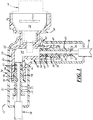
- FIGS. 1-5 show an embodiment of an automotive selective catalytic reduction (SCR) system sensor holder 10 - also called a sensor manifold - that is used in an SCR exhaust treatment system assembly 12.
- the sensor holder 10 can have quick-connect functionality so that a sensor 14, such as a urea quality sensor, can be more readily inserted into and held in the sensor holder, and released and removed from the sensor holder for service and replacement.
- the sensor holder 10 is placed in-line (feed or return line) in the SCR system assembly 12 downstream of an SCR system tank and upstream of an SCR system dosing injector, which can facilitate retrofitting in SCR system assemblies and can reduce complexity compared to known installations in the SCR system tanks.
- one or more resistance wires can be placed around the sensor holder 10 in order to emit heat to a reducing agent such as urea passing through the holder.
- a reducing agent such as urea passing through the holder.
- the sensor holder 10 can be used with other reducing agents and with other types of sensors.
- the SCR system assembly 12 carries pressurized urea fluid at least part way between a urea tank and a urea dosing injector.
- the SCR system assembly 12 can have different designs, constructions, and components, depending upon, among other considerations, its particular vehicle application.
- the SCR system assembly 12 includes the sensor holder 10, a first SCR line 16, an inlet connector 18, a second SCR line 20, an outlet connector 22, and a cover 24.
- the first SCR line 16, or urea line carries urea fluid from the urea tank and to the sensor holder 10.
- the first SCR line 16 can be fitted with a coupling to facilitate its connection to the urea tank.
- the first SCR line 16 can have one or more resistance wires wound or otherwise placed at its exterior surface in order to emit heat via resistive heating to the urea fluid passing therethrough.
- the first SCR line 16 is connected to the inlet connector 18.
- the inlet connector 18 facilitates fluid-tight connection between the first SCR line 16 and the sensor holder 10.
- the first SCR line 16 is inserted tightly (e.g., press-fit) into a first end 28, and a second end 30 of the inlet connector 18 is inserted into the sensor holder 10.
- the second end 30 can have a ramped portion, and gaskets 32 can be provided for sealing.
- a passage 34 extends between the first and second ends 28, 30.
- the inlet connector 18 can have one or more ribs 36 extending from its exterior surface in order to support placement of one or more optional resistance wires, and the inlet connector can have a first groove 38 and a second groove 40 in order to receive insertion of an inlet retainer as described below.
- the second SCR line 20, or urea line carries urea fluid from the sensor holder 10 and to the dosing injector.
- the second SCR line 20 can be fitted with a coupling to facilitate its connection to the dosing injector.
- the second SCR line 20 can have one or more resistance wires wound or otherwise placed at its exterior surface in order to emit heat via resistive heating to the urea fluid passing therethrough.
- the second SCR line 20 is connected to the outlet connector 22.
- the outlet connector 22 facilitates fluid-tight connection between the second SCR line 20 and the sensor holder 10.
- the second SCR line 20 is inserted tightly (e.g., press-fit) into a first end 44, and a second end 46 of the outlet connector 22 is inserted into the sensor holder 10.
- the second end 46 can have a ramped portion, and gaskets 48 can be provided for sealing.
- a passage 50 extends between the first and second ends 44, 46.
- the outlet connector 22 can have one or more ribs 52 extending from its exterior surface in order to support placement of one or more optional resistance wires, and the outlet connector can have a first groove 54 and a second groove 56 in order to receive insertion of an outlet retainer as described below. And, still referring to FIG.
- the cover 24 encloses and protects a part of the sensor holder 10, all of the inlet connector 18, and all of the outlet connector 22.
- the cover 24 also encloses and protects the terminal end 26 of the first SCR line 16 and the terminal end 42 of the second SCR line 20.
- the cover 24 can be made of rubber or another flexible material.
- the SCR system sensor holder 10 connects to the first and second SCR lines 16, 20, and holds the urea quality sensor 14 in position to measure the quality of the urea fluid passing through the sensor holder and between the first and second SCR lines.
- the sensor holder 10 can have different designs, constructions, and components, depending upon, among other considerations, its location in the SCR system assembly 12 and the type and construction of the sensor 14.
- the sensor holder 10 can be a one-piece body made of a plastic material such as PA12 GF50, and the sensor holder includes a tube 58, a chamber 60, a retainer 62, and one or more resistance wires 64. Referring to FIGS.
- the tube 58 has an inlet 66 that receives insertion of the inlet connector 18 and that has a diametrically-reduced portion to complement the ramped portion of the inlet connector.
- the inlet 66 has a first opening 68 and a second opening 70 defined in a wall thereof for receiving portions of an inlet retainer 72 - in particular, for respectively receiving first and second legs of the inlet retainer. Once moved through the first and second openings 68, 70, the first and second legs are respectively received in the first and second grooves 38, 40 of the inlet connector 18.
- the legs, openings 68 and 70, grooves 38 and 40, and the interaction among them, provide a quick-connect functionality between the sensor holder 10 and the inlet connector 18.
- a molding material can be overmolded onto the inlet 66 at the legs, openings 68 and 70, and grooves 38 and 40.
- the tube 58 has an outlet 74 that receives insertion of the outlet connector 22 and that has a diametrically-reduced portion to complement the ramped portion of the outlet connector.
- the outlet 74 has a first opening 76 and a second opening 78 defined in a wall thereof for receiving portions of an outlet retainer 79 - in particular, for respectively receiving first and second legs of the outlet retainer. Once moved through the first and second openings 76, 78, the first and second legs are respectively received in the first and second grooves 54, 56 of the outlet connector 22.
- the legs, openings 76 and 78, grooves 54 and 56, and the interaction among them, provide a quick-connect functionality between the sensor holder 10 and the outlet connector 22.
- a molding material can be overmolded onto the outlet 74 at the legs, openings 76 and 78, and grooves 54 and 56.
- a passage 80 of the tube 58 extends between the inlet 66 and the outlet 74, and carries urea fluid therebetween.
- the passage 80 fluidly communicates directly with the passages 34, 50 of the inlet and outlet connectors 18, 22.
- the passage 80 is open to, and accessible with, the chamber 60 so that a measuring tip of the urea quality sensor 14 can be suspended and introduced into the passing urea fluid in order to take measurements or otherwise sense properties of the urea fluid.
- the tube 58 has an approximately perpendicular bend 82 formed in its longitudinal extent. The bend 82 is located downstream of the location where the passage 80 is open to the chamber 60. Referring now to FIGS.
- the tube 58 can have a first rib 84 and a second rib 86 to support placement of the resistance wires 64.
- the first rib 84 can be a continuous helical extension extending circumferentially around an exterior surface of the tube 58 adjacent the inlet 66, or can have another structure and arrangement.
- the second rib 86 is a continuous helical extension extending circumferentially around the exterior surface of the tube 58 adjacent the outlet 74, or can have another structure and arrangement.
- the chamber 60 receives insertion of the urea quality sensor 14.
- the chamber 60 can have different designs, constructions, and components, depending upon, among other considerations, the type and construction of the sensor 14.
- the chamber 60 has a chamber wall 88 that defines an interior 90.
- the interior 90 provides a space to accommodate insertion of the urea quality sensor 14 and to complement the shape of the sensor, and therefore can provide different spaces and shapes for different sensors.
- the chamber wall 88 has an interior surface 92 with a series of diametrically-reduced sections for suitably seating the urea quality sensor 14.
- a first and second slot 94, 96 are provided at the interior surface 92 and receive a complementarily portion or structure of the sensor.
- the chamber 60 has an open top 98, and has an open bottom 100 that is open to, and accessible with, the passage 80 of the tube 58 so that the measuring tip of the urea quality sensor 14 can be suspended and introduced into the passing urea fluid (shown in FIG. 1 ).
- a first and second opening 102, 104 are defined in the chamber wall 88 and extend completely through the chamber wall and lead to the interior 90.
- the first and second openings 102, 104 interact with the retainer 62 to provide a quick-connect functionality between the sensor holder 10 and the urea quality sensor 14, as described in more detail below. And, at an exterior surface 106, a first and second recess 108, 110 are provided for seating the retainer 62, and a first and second cover 112, 114 are provided for concealing a portion of the retainer.
- the retainer 62 interacts with the chamber 60 to provide a quick-connect functionality so that the urea quality sensor 14 is readily inserted into and held in the sensor holder 10, and can be subsequently released and removed from the sensor holder for service and replacement.
- the retainer 62 can have different designs, constructions, and components, depending upon, among other considerations, the construction and design of the chamber 60 and the type and construction of the sensor 14.
- the retainer 62 is a one-piece stainless steel wire spring that is inwardly biased and that has a first leg 116, a second leg 118, and a bridge 120 extending therebetween.
- the first and second legs 116, 118 can be substantially similar in shape and size.
- the retainer 62 In a first position in use, the retainer 62 is somewhat loosely carried by the chamber 60 with an end portion of the first leg 116 seated in the first recess 108, and an end portion of the second leg 118 seated in the second recess 110 (shown by phantom in FIG. 2 ).
- the bridge 120 is externally serviceable and accessible by a user, and the first and second legs 116, 118 are located outside of the interior 90 and outside of the first and second openings 102, 104.
- the bridge 120 can be moved toward the interior 90 and toward the exterior surface 106 where the bridge can abut against the exterior surface between a pair of flanges 122, 124.
- the flanges 122, 124 help prevent inadvertent dislodging of the bridge 120 when the retainer 62 is in the second position.
- the first and second legs 116, 118 are moved toward the interior 90 and bear against the exterior surface 106 as the legs are slid thereover in movement.
- the first and second legs 116, 118 are moved respectively through the first and second openings 102, 104 and into the interior 90 (shown by solid line in FIG. 2 ).
- first and second legs 116, 118 are respectively located generally underneath the first and second covers 112, 114.
- the legs 116, 118 and openings 102, 104 provide the quick-connect functionality.
- the retainer 62 is brought to the first position and the sensor can be placed inside of the chamber 60.
- the retainer 62 is brought to the second position and the first and second legs 116, 118 are moved through the first and second openings 102, 104 and into recesses or against edged portions of the sensor.
- the urea quality sensor 14 is thereby secured within the sensor holder 10 and prevented from being removed out of the chamber 60.
- a tight fit with one or more gaskets can be provided between the urea quality sensor 14 and the chamber 60 so that no other connection techniques are needed apart from the retainer 62. And conversely, to release the urea quality sensor 14 out of the sensor holder 10, the retainer 62 is brought back to the first position and the sensor can be removed out of the chamber 60.
- the resistance wires 64 emit a suitable amount of heat via resistive heating directly to the tube 58 and thereby indirectly to the urea fluid passing through the tube. The heat helps ensure that the urea fluid reaches a proper temperature for flow through the tube 58 and for measurements and sensing by the urea quality sensor 14.
- the resistance wires 64 can be copper wires wound about the tube 58 and around the first and second ribs 84, 86.
- the resistance wires 64 can be a single wire wound around both of the first and second ribs 84, 86, or can be separate and distinct wires wound around the first and second ribs.
- the wires can be electrically coupled to an electronic control unit (ECU) such as an automobile control unit, or to another device.
- ECU electronice control unit
- This description of the resistance wires also applies to the previously-mentioned resistance wires of the first SCR line 16, resistance wires of the inlet connector 18, resistance wires of the second SCR line 20, and resistance wires of the outlet connector 22.
- the SCR system assembly 12 and the SCR system sensor holder 10 can have different designs, constructions, and components.
- the tube of the sensor holder need not have a bend and instead could be uni-directional or could have a T-shape with a total of three inlet(s) and outlet(s);
- the resistance wires need not be provided for the sensor holder, or the heat emitting functionality could be provided by heating elements other than the resistance wires;
- the quick-connect functionality between the chamber and the retainer could be provided in different ways including ways without the retainer, such as a quick-connection with an inter-connecting or inter-engaging structure that engages the valve or that is received in a recess of the valve, with a quick-connection having a recess to receive a structure or portion of the valve, or with a quick-connection interlocking with a snap-fit motion or with a twist-lock motion; and likewise, the quick-connect functionality between the inlet and outlet of the tube and the respective inlet and
Claims (4)
- Kfz-Systemanordnung zur selektiven katalytischen Reduktion (selective catalytic reduction, SCR), wobei die Anordnung umfasst:einen Halter (10), der eine Röhre (58), eine Kammer (60) und ein Heizelement (64) umfasst, wobei die Röhre (58) einen Einlass (66), einen Auslass (74) und einen Durchgang (80) zwischen dem Einlass (66) und dem Auslass (74) aufweist, wobei die Kammer (60) einen für den Durchgang zugänglichen Innenraum aufweist, wobei der Innenraum einen SCR-Systemsensor (14) aufnimmt, wobei das Heizelement (64) Wärme an mindestens einen Teilabschnitt der Röhre (58) abgibt;einen Einlassverbinder (18), der in den Einlass (66) der Röhre eingefügt ist;einen Auslassverbinder (22), der in den Auslass (74) der Röhre eingefügt ist;eine erste SCR-Leitung (16), die mit dem Einlassverbinder (18) verbunden ist; undeine zweite SCR-Leitung, die mit dem Auslassverbinder verbunden istdadurch gekennzeichnet, dass das Heizelement (64) ein Widerstandsdraht ist, der um mindestens einen Teilabschnitt der Röhre (58) gewickelt ist, um Wärme an die Röhre abzugeben.
- Kfz-SCR-Systemanordnung nach Anspruch 1, weiter umfassend eine flexible Abdeckung, die die Röhre des Halters umschließt, die den Einlassverbinder umschließt, die den Auslassverbinder umschließt, die einen Teilabschnitt der ersten SCR-Leitung umschließt und die einen Teilabschnitt der zweiten SCR-Leitung umschließt.
- Kfz-SCR-Systemanordnung nach Anspruch 1 oder Anspruch 2, wobei der Halter weiter eine Schnellverbindung mit einer Verbindungsstruktur zum lösbaren Halten des SCR-Systemsensors innerhalb des Innenraums des Halters umfasst.
- Kfz-SCR-Systemanordnung nach einem vorstehenden Anspruch, wobei der Halter weiter eine erste Schnellverbindung mit einer Verbindungsstruktur zum lösbaren Sichern des Einlassverbinders innerhalb des Einlasses der Röhre umfasst und eine zweite Schnellverbindung mit einer Verbindungsstruktur zum lösbaren Sichern des Auslassverbinders innerhalb des Auslasses der Röhre umfasst.
Applications Claiming Priority (3)
| Application Number | Priority Date | Filing Date | Title |
|---|---|---|---|
| US201261604379P | 2012-02-28 | 2012-02-28 | |
| PCT/US2013/028326 WO2013130810A1 (en) | 2012-02-28 | 2013-02-28 | Automotive selective catalytic reduction (scr) system sensor holder and assembly |
| EP13754763.4A EP2820259B1 (de) | 2012-02-28 | 2013-02-28 | Sensorhalter und anordnung für selektives katalytisches reduktionssystem eines fahrzeuges |
Related Parent Applications (2)
| Application Number | Title | Priority Date | Filing Date |
|---|---|---|---|
| EP13754763.4A Division EP2820259B1 (de) | 2012-02-28 | 2013-02-28 | Sensorhalter und anordnung für selektives katalytisches reduktionssystem eines fahrzeuges |
| EP13754763.4A Division-Into EP2820259B1 (de) | 2012-02-28 | 2013-02-28 | Sensorhalter und anordnung für selektives katalytisches reduktionssystem eines fahrzeuges |
Publications (2)
| Publication Number | Publication Date |
|---|---|
| EP3203047A1 EP3203047A1 (de) | 2017-08-09 |
| EP3203047B1 true EP3203047B1 (de) | 2018-10-17 |
Family
ID=49001553
Family Applications (2)
| Application Number | Title | Priority Date | Filing Date |
|---|---|---|---|
| EP17162739.1A Revoked EP3203047B1 (de) | 2012-02-28 | 2013-02-28 | Sensorhalter und anordnung für selektives katalytisches reduktionssystem eines fahrzeuges |
| EP13754763.4A Not-in-force EP2820259B1 (de) | 2012-02-28 | 2013-02-28 | Sensorhalter und anordnung für selektives katalytisches reduktionssystem eines fahrzeuges |
Family Applications After (1)
| Application Number | Title | Priority Date | Filing Date |
|---|---|---|---|
| EP13754763.4A Not-in-force EP2820259B1 (de) | 2012-02-28 | 2013-02-28 | Sensorhalter und anordnung für selektives katalytisches reduktionssystem eines fahrzeuges |
Country Status (9)
| Country | Link |
|---|---|
| US (1) | US9388932B2 (de) |
| EP (2) | EP3203047B1 (de) |
| JP (1) | JP6131277B2 (de) |
| KR (1) | KR20140129176A (de) |
| CN (1) | CN104145095B (de) |
| BR (1) | BR112014021239A2 (de) |
| CA (1) | CA2865495C (de) |
| MX (1) | MX353573B (de) |
| WO (1) | WO2013130810A1 (de) |
Families Citing this family (16)
| Publication number | Priority date | Publication date | Assignee | Title |
|---|---|---|---|---|
| EP2846014B1 (de) * | 2013-09-10 | 2017-03-15 | Inergy Automotive Systems Research (Société Anonyme) | Modul für ein SCR-System und System damit |
| CN104948271B (zh) * | 2014-03-25 | 2017-12-08 | 浙江福爱电子有限公司 | 一种scr喷射计量模块及控制方法 |
| DE102014005817A1 (de) | 2014-04-24 | 2015-10-29 | Voss Automotive Gmbh | Mehrteilige beheizbare Medienleitung, Leitungsverbindungseinrichtung für eine solche sowie Verfahren zum Herstellen einer solchen |
| US10012121B2 (en) * | 2014-05-20 | 2018-07-03 | Ssi Technologies, Inc. | Reduction of aeration interference via tortuous path and sensor boot |
| EP3150813A1 (de) * | 2015-09-30 | 2017-04-05 | Plastic Omnium Advanced Innovation and Research | Versorgungsleitungssystem für ein fahrzeug |
| JP6563854B2 (ja) * | 2016-05-20 | 2019-08-21 | 株式会社ニフコ | 管状体のロック機構 |
| US10396500B2 (en) | 2016-08-31 | 2019-08-27 | Norma U.S. Holding Llc | Electrically conductive conduit assembly |
| GB2559998B (en) * | 2017-02-24 | 2019-05-08 | Pipe Transf Ltd | Pipeline apparatus with releasably lockable device |
| EP3369901B1 (de) * | 2017-03-03 | 2019-10-16 | MEAS France | Harnstoffsensorschutzanordnung und harnstoffsensorsystem |
| EP3382254B1 (de) * | 2017-03-29 | 2020-06-03 | TI Automotive (Fuldabrück) GmbH | Beheizte rohrleitung mit stecker sowie ein verfahren zum betrieb dieser rohrleitung |
| NO343381B1 (en) * | 2017-10-05 | 2019-02-18 | Sentec As | Level sensor assembly |
| US10590825B2 (en) | 2017-11-27 | 2020-03-17 | Voss Automotive Gmbh | Line connector with integrated sensor for measurement of urea solutions |
| US10508577B2 (en) | 2017-11-27 | 2019-12-17 | Voss Automotive Gmbh | Line connector with integrated sensor for measurement of urea solutions |
| DE102017127936A1 (de) * | 2017-11-27 | 2019-05-29 | Voss Automotive Gmbh | Leitungsverbinder mit integriertem Sensor zur Messung von Harnstoff-Lösungen |
| CN109488870B (zh) * | 2018-12-17 | 2021-02-05 | 宁波世峻汽配科技有限公司 | 一种机油冷却管 |
| EP4217636A1 (de) * | 2020-09-25 | 2023-08-02 | Parker-Hannifin Corporation | Frostbeständige schnellverbindungsarmatur |
Citations (3)
| Publication number | Priority date | Publication date | Assignee | Title |
|---|---|---|---|---|
| US20080202108A1 (en) | 2007-02-27 | 2008-08-28 | Jurgen Stritzinger | Reductant supply system for a waste gas cleaning catalyst of an internal combustion engine and a plug-in connection for connecting heatable fluid ducts |
| WO2008131993A1 (de) | 2007-04-26 | 2008-11-06 | Voss Automotive Gmbh | Leitungsverbinder für medienleitungen |
| WO2012079833A1 (de) | 2010-12-15 | 2012-06-21 | Contitech Schlauch Gmbh | Beheizbare anschlussvorrichtung für medienführende, elektrisch beheizbare schläuche |
Family Cites Families (61)
| Publication number | Priority date | Publication date | Assignee | Title |
|---|---|---|---|---|
| DE8704903U1 (de) | 1987-04-02 | 1987-05-27 | Rehau Ag + Co, 8673 Rehau, De | |
| FR2637021B1 (fr) | 1988-09-23 | 1993-12-03 | Peugeot Automobiles | Dispositif de regulation de la pression du carburant d'un moteur a injection, presentant une grande facilite de montage et de demontage |
| US5000614A (en) * | 1989-05-05 | 1991-03-19 | Huron Products Corporation | Conduit quick connector assembly having a ramped housing with a hair pin retainer |
| JPH0875585A (ja) | 1994-09-09 | 1996-03-22 | Smc Corp | 圧力検出器の接続構造 |
| JPH08219352A (ja) | 1995-02-09 | 1996-08-30 | Toto Ltd | 管継手 |
| US5693887A (en) | 1995-10-03 | 1997-12-02 | Nt International, Inc. | Pressure sensor module having non-contaminating body and isolation member |
| US5869766A (en) * | 1995-10-03 | 1999-02-09 | Nt International, Inc. | Non-contaminating pressure transducer module |
| DE19653405C2 (de) * | 1996-12-20 | 1999-06-10 | Bosch Gmbh Robert | Gemischabgabevorrichtung |
| US5976475A (en) * | 1997-04-02 | 1999-11-02 | Clean Diesel Technologies, Inc. | Reducing NOx emissions from an engine by temperature-controlled urea injection for selective catalytic reduction |
| JP3202942B2 (ja) | 1997-07-15 | 2001-08-27 | トヨタ自動車株式会社 | 流体用センサ |
| JP3708691B2 (ja) | 1997-10-17 | 2005-10-19 | シーケーディ株式会社 | 圧力検出器 |
| JPH11325361A (ja) | 1998-05-19 | 1999-11-26 | Togo Seisakusyo Corp | コネクタにおけるパイプ組付け状態の確認構造 |
| DE19902431B4 (de) | 1999-01-22 | 2006-04-27 | Siemens Ag | Zwischenstück mit einem Anschluß von Waschflüssigkeitsleitungen einer Scheibenreinigungsanlage |
| US6343814B1 (en) | 1999-11-08 | 2002-02-05 | Ti Group Automotive Systems, Llc | Insertion verifier dust cap |
| JP3981224B2 (ja) | 1999-11-19 | 2007-09-26 | 東海ゴム工業株式会社 | コネクター及びこれを用いた樹脂チューブ接続構造体 |
| US6363771B1 (en) * | 1999-11-24 | 2002-04-02 | Caterpillar Inc. | Emissions diagnostic system |
| DE19961287A1 (de) * | 1999-12-18 | 2001-06-21 | Bosch Gmbh Robert | Verbindungsvorrichtung zum Verbinden zweier koaxial zueinander angeordneter Elemente |
| JP3600509B2 (ja) * | 2000-06-23 | 2004-12-15 | トヨタ自動車株式会社 | 内燃機関の排気浄化装置 |
| DE10032616A1 (de) | 2000-07-08 | 2002-01-24 | Mhm Harzbecher Medizintechnik | Systemelemente zur Druckmessung in extrakorporalen Kreisläufen |
| JP4447142B2 (ja) * | 2000-10-06 | 2010-04-07 | トヨタ自動車株式会社 | 内燃機関の排気浄化装置 |
| JP2004520590A (ja) * | 2001-02-06 | 2004-07-08 | エルスター メータリング リミテッド | 流量計 |
| DE10115322A1 (de) * | 2001-03-28 | 2002-10-17 | Bosch Gmbh Robert | Kraftstoff-Einspritzvorrichtung für Brennkraftmaschinen, insbesondere Common-Rail-Injektor |
| JP4291989B2 (ja) * | 2002-10-01 | 2009-07-08 | 株式会社パイオラックス | 配管用コネクタ |
| DE10255267A1 (de) | 2002-11-21 | 2004-06-03 | Behr Thermot-Tronik Gmbh | Anordnung zur Temperaturmessung und Montageelement |
| DE10259395A1 (de) | 2002-12-19 | 2004-07-22 | Festo Ag & Co. | Anschlussstück für Fluidleitungen |
| DE10322124A1 (de) | 2003-05-16 | 2004-12-02 | Robert Bosch Gmbh | Vorrichtung zur Bestimmung wenigstens eines Parameters eines in einer Leitung strömenden Mediums |
| WO2005044478A2 (en) | 2003-10-20 | 2005-05-19 | International Resistive Company | Resistive film on aluminum tube |
| US7341097B2 (en) | 2003-11-03 | 2008-03-11 | Chrysler Llc | Coolant sensor and bleed valve |
| JP4529658B2 (ja) | 2003-11-28 | 2010-08-25 | 東海ゴム工業株式会社 | クイックコネクタ |
| FR2864700A1 (fr) | 2003-12-31 | 2005-07-01 | Siemens Vdo Automotive | Procede d'enrobage d'une unite electronique d'un capteur et capteur correspondant |
| JP2005227027A (ja) | 2004-02-10 | 2005-08-25 | Denso Corp | 温度センサ、温度センサ収容機構 |
| JP2006183764A (ja) | 2004-12-27 | 2006-07-13 | Onda Seisakusho Seki Kojo:Kk | 継手 |
| JP2008530446A (ja) * | 2005-02-16 | 2008-08-07 | アイエムアイ・ビジョン・リミテッド | 排気ガス処理 |
| US7438328B2 (en) | 2005-03-25 | 2008-10-21 | Tokai Rubber Industries, Ltd. | Quick connector |
| DE502005007504D1 (de) | 2005-04-05 | 2009-07-30 | Dbk David & Baader Gmbh | Elektrische Heizvorrichtung zum Beheizen eines Mediums in einem Schlauch |
| DE202006003590U1 (de) | 2005-04-14 | 2006-06-01 | Schlemmer Gmbh | Beheizbarer Wellschlauch |
| US20060251548A1 (en) * | 2005-05-06 | 2006-11-09 | Willey Ray L | Exhaust aftertreatment device |
| US7466147B2 (en) | 2005-08-08 | 2008-12-16 | Continental Automotive Systems Us, Inc. | Fluid quality sensor |
| JP4957081B2 (ja) | 2005-09-15 | 2012-06-20 | 株式会社デンソー | 流量測定装置 |
| US7325463B2 (en) | 2005-09-16 | 2008-02-05 | Bendix Commercial Vehicle Systems, Llc | Fluid sensor assembly |
| WO2007032034A1 (en) | 2005-09-16 | 2007-03-22 | Dayco Fluid Technologies S.P.A. | Pipe fitting for a heatable piping of a scr system |
| SE529417C2 (sv) | 2005-12-22 | 2007-08-07 | Volvo Lastvagnar Ab | Ledningsnät för ett fordon |
| US20070187869A1 (en) * | 2006-02-15 | 2007-08-16 | Siemens Vdo Automotive Corporation | Single mold active speed sensor |
| FR2905161B1 (fr) | 2006-08-25 | 2012-04-20 | Inergy Automotive Systems Res | Raccord avec element chauffant integre. |
| WO2008071022A1 (de) * | 2006-12-11 | 2008-06-19 | Kistler Holding Ag | Adapter für drucksensoren |
| SE0700478L (sv) | 2007-02-27 | 2008-08-28 | Promech Lab Ab | Anordning och metod för detektering av partiklar i ett partikelhaltigt flöde |
| JP4710868B2 (ja) | 2007-04-25 | 2011-06-29 | トヨタ自動車株式会社 | 内燃機関の排気浄化装置 |
| ATE533989T1 (de) * | 2007-04-26 | 2011-12-15 | Voss Automotive Gmbh | Leitungsverbinder für medienleitungen |
| DE202007009588U1 (de) | 2007-04-26 | 2008-09-04 | Voss Automotive Gmbh | Leitungsverbinder für Medienleitungen |
| US7699356B2 (en) | 2007-05-10 | 2010-04-20 | Craig Assgembly, Inc. | Quick connector for fluid conduit |
| DE102007027413B4 (de) * | 2007-06-11 | 2016-10-20 | Eichenauer Heizelemente Gmbh & Co. Kg | Reduktionsmittelversorgungssystem für einen Abgasreinigungskatalysator eines Verbrennungsmotors |
| PL2222995T3 (pl) | 2007-12-21 | 2015-04-30 | Voss Automotive Gmbh | Element połączeniowy przewodów dla przewodów dla mediów oraz zespolony przewód dla mediów z co najmniej jednym takim elementem połączeniowym przewodów |
| DE202007018089U1 (de) | 2007-12-21 | 2009-05-07 | Voss Automotive Gmbh | Beheizbare Medienleitung |
| IT1391189B1 (it) | 2008-08-01 | 2011-11-18 | Eltek Spa | Misuratore di flusso |
| DE202009012230U1 (de) | 2009-06-23 | 2010-11-04 | Voss Automotive Gmbh | Elektrisch beheizbare Medienleitung sowie Leitungsverbinder |
| IT1396306B1 (it) * | 2009-11-06 | 2012-11-16 | Eltek Spa | Riscaldatore elettrico, dispositivo di riscaldamento e sistema di riscaldamento. |
| US8002315B2 (en) | 2009-12-23 | 2011-08-23 | General Electric Corporation | Device for measuring fluid properties in caustic environments |
| DE102009060363A1 (de) * | 2009-12-24 | 2011-06-30 | Volkswagen AG, 38440 | Verbindungseinheit |
| US20130213013A1 (en) * | 2011-01-14 | 2013-08-22 | Cummins Ip, Inc. | Exhaust gas sensor module |
| WO2013054609A1 (ja) * | 2011-10-12 | 2013-04-18 | 株式会社堀場製作所 | ガス分析装置 |
| EP2684597A1 (de) * | 2012-07-14 | 2014-01-15 | Deutz AG | Verfahren zur Verminderung von Stickoxiden aus Dieselmotorenabgasen |
-
2013
- 2013-02-28 CA CA2865495A patent/CA2865495C/en not_active Expired - Fee Related
- 2013-02-28 BR BR112014021239-2A patent/BR112014021239A2/pt not_active Application Discontinuation
- 2013-02-28 CN CN201380011482.4A patent/CN104145095B/zh not_active Expired - Fee Related
- 2013-02-28 JP JP2014560040A patent/JP6131277B2/ja active Active
- 2013-02-28 EP EP17162739.1A patent/EP3203047B1/de not_active Revoked
- 2013-02-28 MX MX2014010276A patent/MX353573B/es active IP Right Grant
- 2013-02-28 KR KR20147025659A patent/KR20140129176A/ko not_active Application Discontinuation
- 2013-02-28 US US13/780,924 patent/US9388932B2/en active Active
- 2013-02-28 WO PCT/US2013/028326 patent/WO2013130810A1/en active Application Filing
- 2013-02-28 EP EP13754763.4A patent/EP2820259B1/de not_active Not-in-force
Patent Citations (4)
| Publication number | Priority date | Publication date | Assignee | Title |
|---|---|---|---|---|
| US20080202108A1 (en) | 2007-02-27 | 2008-08-28 | Jurgen Stritzinger | Reductant supply system for a waste gas cleaning catalyst of an internal combustion engine and a plug-in connection for connecting heatable fluid ducts |
| DE102008006323B4 (de) | 2007-02-27 | 2014-04-30 | Eichenauer Heizelemente Gmbh & Co. Kg | Reduktionsmittelversorgungssystem für einen Abgasreinigungskatalysator eines Verbrennungsmotors und Steckverbindung zum Anschließen von beheizbaren Flüssigkeitsleitungen |
| WO2008131993A1 (de) | 2007-04-26 | 2008-11-06 | Voss Automotive Gmbh | Leitungsverbinder für medienleitungen |
| WO2012079833A1 (de) | 2010-12-15 | 2012-06-21 | Contitech Schlauch Gmbh | Beheizbare anschlussvorrichtung für medienführende, elektrisch beheizbare schläuche |
Also Published As
| Publication number | Publication date |
|---|---|
| EP2820259A1 (de) | 2015-01-07 |
| CA2865495C (en) | 2019-06-11 |
| EP2820259A4 (de) | 2016-03-02 |
| CN104145095B (zh) | 2017-09-12 |
| KR20140129176A (ko) | 2014-11-06 |
| US9388932B2 (en) | 2016-07-12 |
| EP3203047A1 (de) | 2017-08-09 |
| CA2865495A1 (en) | 2013-09-06 |
| EP2820259B1 (de) | 2017-05-31 |
| BR112014021239A2 (pt) | 2020-06-23 |
| WO2013130810A1 (en) | 2013-09-06 |
| MX2014010276A (es) | 2015-05-08 |
| MX353573B (es) | 2018-01-18 |
| US20130220467A1 (en) | 2013-08-29 |
| CN104145095A (zh) | 2014-11-12 |
| JP2015515567A (ja) | 2015-05-28 |
| JP6131277B2 (ja) | 2017-05-17 |
Similar Documents
| Publication | Publication Date | Title |
|---|---|---|
| EP3203047B1 (de) | Sensorhalter und anordnung für selektives katalytisches reduktionssystem eines fahrzeuges | |
| US9816758B2 (en) | Integrated heater assembly for a tank, methods for installing and manufacturing such an assembly and a vehicle inluding such a heater assembly | |
| US8322134B2 (en) | Sliding fit, pipe arrangement and exhaust gas treatment device | |
| JP5789336B2 (ja) | 反応剤を計量分配するためのポンプアッセンブリ | |
| EP2960456A1 (de) | Winkelförmige und kompakte Abgasnachbehandlungseinrichtung | |
| KR20140124731A (ko) | 환원제 가열에 의한 자동차의 선택적 촉매 환원을 위한 환원제 분배 유닛 | |
| EP3673193B1 (de) | Verbinder für einen beheizbaren fluidkanal, insbesondere eines scr-systems oder eines wasserinjektionssystems | |
| KR101684759B1 (ko) | 액체 첨가제 공급 장치 | |
| JP6238587B2 (ja) | 耐コーキング後処理投与弁および製造方法 | |
| CN103747974B (zh) | 储液箱装置及废气净化装置 | |
| US20210131327A1 (en) | Dosing module for use in aftertreatment systems for internal combustion engines | |
| KR101675461B1 (ko) | 농기계용 엔진 배기가스 복합정화장치 | |
| CN107735551B (zh) | 用于安装的外珠状体和接合面 | |
| US20230009619A1 (en) | Insulated exhaust gas conduit systems | |
| CN219101447U (zh) | 还原剂罐和包括还原剂罐的选择性催化还原装置 | |
| CN106285859B (zh) | 带有用于引导加热流体的集成的流体通道的还原剂箱 | |
| GB2619833A (en) | Insulated exhaust gas conduit systems | |
| GB2602209A (en) | Dosing module for use in aftertreatment systems for internal combustion engines |
Legal Events
| Date | Code | Title | Description |
|---|---|---|---|
| PUAI | Public reference made under article 153(3) epc to a published international application that has entered the european phase |
Free format text: ORIGINAL CODE: 0009012 |
|
| STAA | Information on the status of an ep patent application or granted ep patent |
Free format text: STATUS: REQUEST FOR EXAMINATION WAS MADE |
|
| 17P | Request for examination filed |
Effective date: 20170324 |
|
| AC | Divisional application: reference to earlier application |
Ref document number: 2820259 Country of ref document: EP Kind code of ref document: P |
|
| AK | Designated contracting states |
Kind code of ref document: A1 Designated state(s): AL AT BE BG CH CY CZ DE DK EE ES FI FR GB GR HR HU IE IS IT LI LT LU LV MC MK MT NL NO PL PT RO RS SE SI SK SM TR |
|
| GRAP | Despatch of communication of intention to grant a patent |
Free format text: ORIGINAL CODE: EPIDOSNIGR1 |
|
| STAA | Information on the status of an ep patent application or granted ep patent |
Free format text: STATUS: GRANT OF PATENT IS INTENDED |
|
| RIC1 | Information provided on ipc code assigned before grant |
Ipc: F16L 37/14 20060101ALI20180509BHEP Ipc: F01N 3/20 20060101AFI20180509BHEP Ipc: F16L 55/00 20060101ALI20180509BHEP |
|
| INTG | Intention to grant announced |
Effective date: 20180528 |
|
| GRAS | Grant fee paid |
Free format text: ORIGINAL CODE: EPIDOSNIGR3 |
|
| GRAA | (expected) grant |
Free format text: ORIGINAL CODE: 0009210 |
|
| STAA | Information on the status of an ep patent application or granted ep patent |
Free format text: STATUS: THE PATENT HAS BEEN GRANTED |
|
| AC | Divisional application: reference to earlier application |
Ref document number: 2820259 Country of ref document: EP Kind code of ref document: P |
|
| AK | Designated contracting states |
Kind code of ref document: B1 Designated state(s): AL AT BE BG CH CY CZ DE DK EE ES FI FR GB GR HR HU IE IS IT LI LT LU LV MC MK MT NL NO PL PT RO RS SE SI SK SM TR |
|
| REG | Reference to a national code |
Ref country code: GB Ref legal event code: FG4D |
|
| REG | Reference to a national code |
Ref country code: CH Ref legal event code: EP |
|
| REG | Reference to a national code |
Ref country code: IE Ref legal event code: FG4D |
|
| REG | Reference to a national code |
Ref country code: DE Ref legal event code: R096 Ref document number: 602013045430 Country of ref document: DE Ref country code: AT Ref legal event code: REF Ref document number: 1054296 Country of ref document: AT Kind code of ref document: T Effective date: 20181115 |
|
| REG | Reference to a national code |
Ref country code: SE Ref legal event code: TRGR |
|
| REG | Reference to a national code |
Ref country code: NL Ref legal event code: MP Effective date: 20181017 |
|
| REG | Reference to a national code |
Ref country code: LT Ref legal event code: MG4D |
|
| REG | Reference to a national code |
Ref country code: AT Ref legal event code: MK05 Ref document number: 1054296 Country of ref document: AT Kind code of ref document: T Effective date: 20181017 |
|
| PG25 | Lapsed in a contracting state [announced via postgrant information from national office to epo] |
Ref country code: NL Free format text: LAPSE BECAUSE OF FAILURE TO SUBMIT A TRANSLATION OF THE DESCRIPTION OR TO PAY THE FEE WITHIN THE PRESCRIBED TIME-LIMIT Effective date: 20181017 |
|
| PG25 | Lapsed in a contracting state [announced via postgrant information from national office to epo] |
Ref country code: AT Free format text: LAPSE BECAUSE OF FAILURE TO SUBMIT A TRANSLATION OF THE DESCRIPTION OR TO PAY THE FEE WITHIN THE PRESCRIBED TIME-LIMIT Effective date: 20181017 Ref country code: LV Free format text: LAPSE BECAUSE OF FAILURE TO SUBMIT A TRANSLATION OF THE DESCRIPTION OR TO PAY THE FEE WITHIN THE PRESCRIBED TIME-LIMIT Effective date: 20181017 Ref country code: PL Free format text: LAPSE BECAUSE OF FAILURE TO SUBMIT A TRANSLATION OF THE DESCRIPTION OR TO PAY THE FEE WITHIN THE PRESCRIBED TIME-LIMIT Effective date: 20181017 Ref country code: HR Free format text: LAPSE BECAUSE OF FAILURE TO SUBMIT A TRANSLATION OF THE DESCRIPTION OR TO PAY THE FEE WITHIN THE PRESCRIBED TIME-LIMIT Effective date: 20181017 Ref country code: FI Free format text: LAPSE BECAUSE OF FAILURE TO SUBMIT A TRANSLATION OF THE DESCRIPTION OR TO PAY THE FEE WITHIN THE PRESCRIBED TIME-LIMIT Effective date: 20181017 Ref country code: BG Free format text: LAPSE BECAUSE OF FAILURE TO SUBMIT A TRANSLATION OF THE DESCRIPTION OR TO PAY THE FEE WITHIN THE PRESCRIBED TIME-LIMIT Effective date: 20190117 Ref country code: ES Free format text: LAPSE BECAUSE OF FAILURE TO SUBMIT A TRANSLATION OF THE DESCRIPTION OR TO PAY THE FEE WITHIN THE PRESCRIBED TIME-LIMIT Effective date: 20181017 Ref country code: IS Free format text: LAPSE BECAUSE OF FAILURE TO SUBMIT A TRANSLATION OF THE DESCRIPTION OR TO PAY THE FEE WITHIN THE PRESCRIBED TIME-LIMIT Effective date: 20190217 Ref country code: LT Free format text: LAPSE BECAUSE OF FAILURE TO SUBMIT A TRANSLATION OF THE DESCRIPTION OR TO PAY THE FEE WITHIN THE PRESCRIBED TIME-LIMIT Effective date: 20181017 Ref country code: NO Free format text: LAPSE BECAUSE OF FAILURE TO SUBMIT A TRANSLATION OF THE DESCRIPTION OR TO PAY THE FEE WITHIN THE PRESCRIBED TIME-LIMIT Effective date: 20190117 |
|
| PG25 | Lapsed in a contracting state [announced via postgrant information from national office to epo] |
Ref country code: GR Free format text: LAPSE BECAUSE OF FAILURE TO SUBMIT A TRANSLATION OF THE DESCRIPTION OR TO PAY THE FEE WITHIN THE PRESCRIBED TIME-LIMIT Effective date: 20190118 Ref country code: PT Free format text: LAPSE BECAUSE OF FAILURE TO SUBMIT A TRANSLATION OF THE DESCRIPTION OR TO PAY THE FEE WITHIN THE PRESCRIBED TIME-LIMIT Effective date: 20190217 Ref country code: RS Free format text: LAPSE BECAUSE OF FAILURE TO SUBMIT A TRANSLATION OF THE DESCRIPTION OR TO PAY THE FEE WITHIN THE PRESCRIBED TIME-LIMIT Effective date: 20181017 Ref country code: AL Free format text: LAPSE BECAUSE OF FAILURE TO SUBMIT A TRANSLATION OF THE DESCRIPTION OR TO PAY THE FEE WITHIN THE PRESCRIBED TIME-LIMIT Effective date: 20181017 |
|
| REG | Reference to a national code |
Ref country code: DE Ref legal event code: R026 Ref document number: 602013045430 Country of ref document: DE |
|
| PLBI | Opposition filed |
Free format text: ORIGINAL CODE: 0009260 |
|
| PLAX | Notice of opposition and request to file observation + time limit sent |
Free format text: ORIGINAL CODE: EPIDOSNOBS2 |
|
| PG25 | Lapsed in a contracting state [announced via postgrant information from national office to epo] |
Ref country code: DK Free format text: LAPSE BECAUSE OF FAILURE TO SUBMIT A TRANSLATION OF THE DESCRIPTION OR TO PAY THE FEE WITHIN THE PRESCRIBED TIME-LIMIT Effective date: 20181017 Ref country code: CZ Free format text: LAPSE BECAUSE OF FAILURE TO SUBMIT A TRANSLATION OF THE DESCRIPTION OR TO PAY THE FEE WITHIN THE PRESCRIBED TIME-LIMIT Effective date: 20181017 |
|
| 26 | Opposition filed |
Opponent name: VOSS AUTOMOTIVE GMBH Effective date: 20190703 |
|
| PG25 | Lapsed in a contracting state [announced via postgrant information from national office to epo] |
Ref country code: SK Free format text: LAPSE BECAUSE OF FAILURE TO SUBMIT A TRANSLATION OF THE DESCRIPTION OR TO PAY THE FEE WITHIN THE PRESCRIBED TIME-LIMIT Effective date: 20181017 Ref country code: SM Free format text: LAPSE BECAUSE OF FAILURE TO SUBMIT A TRANSLATION OF THE DESCRIPTION OR TO PAY THE FEE WITHIN THE PRESCRIBED TIME-LIMIT Effective date: 20181017 Ref country code: EE Free format text: LAPSE BECAUSE OF FAILURE TO SUBMIT A TRANSLATION OF THE DESCRIPTION OR TO PAY THE FEE WITHIN THE PRESCRIBED TIME-LIMIT Effective date: 20181017 Ref country code: RO Free format text: LAPSE BECAUSE OF FAILURE TO SUBMIT A TRANSLATION OF THE DESCRIPTION OR TO PAY THE FEE WITHIN THE PRESCRIBED TIME-LIMIT Effective date: 20181017 |
|
| REG | Reference to a national code |
Ref country code: CH Ref legal event code: PL |
|
| PG25 | Lapsed in a contracting state [announced via postgrant information from national office to epo] |
Ref country code: LU Free format text: LAPSE BECAUSE OF NON-PAYMENT OF DUE FEES Effective date: 20190228 Ref country code: MC Free format text: LAPSE BECAUSE OF FAILURE TO SUBMIT A TRANSLATION OF THE DESCRIPTION OR TO PAY THE FEE WITHIN THE PRESCRIBED TIME-LIMIT Effective date: 20181017 Ref country code: SI Free format text: LAPSE BECAUSE OF FAILURE TO SUBMIT A TRANSLATION OF THE DESCRIPTION OR TO PAY THE FEE WITHIN THE PRESCRIBED TIME-LIMIT Effective date: 20181017 |
|
| PLBB | Reply of patent proprietor to notice(s) of opposition received |
Free format text: ORIGINAL CODE: EPIDOSNOBS3 |
|
| REG | Reference to a national code |
Ref country code: BE Ref legal event code: MM Effective date: 20190228 |
|
| REG | Reference to a national code |
Ref country code: IE Ref legal event code: MM4A |
|
| PG25 | Lapsed in a contracting state [announced via postgrant information from national office to epo] |
Ref country code: LI Free format text: LAPSE BECAUSE OF NON-PAYMENT OF DUE FEES Effective date: 20190228 Ref country code: CH Free format text: LAPSE BECAUSE OF NON-PAYMENT OF DUE FEES Effective date: 20190228 |
|
| PG25 | Lapsed in a contracting state [announced via postgrant information from national office to epo] |
Ref country code: IE Free format text: LAPSE BECAUSE OF NON-PAYMENT OF DUE FEES Effective date: 20190228 |
|
| PG25 | Lapsed in a contracting state [announced via postgrant information from national office to epo] |
Ref country code: BE Free format text: LAPSE BECAUSE OF NON-PAYMENT OF DUE FEES Effective date: 20190228 |
|
| PG25 | Lapsed in a contracting state [announced via postgrant information from national office to epo] |
Ref country code: TR Free format text: LAPSE BECAUSE OF FAILURE TO SUBMIT A TRANSLATION OF THE DESCRIPTION OR TO PAY THE FEE WITHIN THE PRESCRIBED TIME-LIMIT Effective date: 20181017 |
|
| PGFP | Annual fee paid to national office [announced via postgrant information from national office to epo] |
Ref country code: SE Payment date: 20200227 Year of fee payment: 8 Ref country code: GB Payment date: 20200227 Year of fee payment: 8 Ref country code: DE Payment date: 20200227 Year of fee payment: 8 |
|
| PG25 | Lapsed in a contracting state [announced via postgrant information from national office to epo] |
Ref country code: MT Free format text: LAPSE BECAUSE OF NON-PAYMENT OF DUE FEES Effective date: 20190228 |
|
| PGFP | Annual fee paid to national office [announced via postgrant information from national office to epo] |
Ref country code: FR Payment date: 20200225 Year of fee payment: 8 |
|
| PG25 | Lapsed in a contracting state [announced via postgrant information from national office to epo] |
Ref country code: CY Free format text: LAPSE BECAUSE OF FAILURE TO SUBMIT A TRANSLATION OF THE DESCRIPTION OR TO PAY THE FEE WITHIN THE PRESCRIBED TIME-LIMIT Effective date: 20181017 |
|
| PG25 | Lapsed in a contracting state [announced via postgrant information from national office to epo] |
Ref country code: HU Free format text: LAPSE BECAUSE OF FAILURE TO SUBMIT A TRANSLATION OF THE DESCRIPTION OR TO PAY THE FEE WITHIN THE PRESCRIBED TIME-LIMIT; INVALID AB INITIO Effective date: 20130228 |
|
| REG | Reference to a national code |
Ref country code: DE Ref legal event code: R119 Ref document number: 602013045430 Country of ref document: DE |
|
| GBPC | Gb: european patent ceased through non-payment of renewal fee |
Effective date: 20210228 |
|
| PG25 | Lapsed in a contracting state [announced via postgrant information from national office to epo] |
Ref country code: SE Free format text: LAPSE BECAUSE OF NON-PAYMENT OF DUE FEES Effective date: 20210301 Ref country code: GB Free format text: LAPSE BECAUSE OF NON-PAYMENT OF DUE FEES Effective date: 20210228 Ref country code: FR Free format text: LAPSE BECAUSE OF NON-PAYMENT OF DUE FEES Effective date: 20210228 Ref country code: DE Free format text: LAPSE BECAUSE OF NON-PAYMENT OF DUE FEES Effective date: 20210901 |
|
| PGFP | Annual fee paid to national office [announced via postgrant information from national office to epo] |
Ref country code: IT Payment date: 20220222 Year of fee payment: 10 |
|
| PG25 | Lapsed in a contracting state [announced via postgrant information from national office to epo] |
Ref country code: MK Free format text: LAPSE BECAUSE OF FAILURE TO SUBMIT A TRANSLATION OF THE DESCRIPTION OR TO PAY THE FEE WITHIN THE PRESCRIBED TIME-LIMIT Effective date: 20181017 |
|
| RDAF | Communication despatched that patent is revoked |
Free format text: ORIGINAL CODE: EPIDOSNREV1 |
|
| REG | Reference to a national code |
Ref country code: DE Ref legal event code: R103 Ref document number: 602013045430 Country of ref document: DE Ref country code: DE Ref legal event code: R064 Ref document number: 602013045430 Country of ref document: DE |
|
| RDAG | Patent revoked |
Free format text: ORIGINAL CODE: 0009271 |
|
| STAA | Information on the status of an ep patent application or granted ep patent |
Free format text: STATUS: PATENT REVOKED |
|
| REG | Reference to a national code |
Ref country code: CH Ref legal event code: PL |
|
| 27W | Patent revoked |
Effective date: 20220822 |