EP3203000A1 - Door lock with resiliently nestable base - Google Patents
Door lock with resiliently nestable base Download PDFInfo
- Publication number
- EP3203000A1 EP3203000A1 EP17153367.2A EP17153367A EP3203000A1 EP 3203000 A1 EP3203000 A1 EP 3203000A1 EP 17153367 A EP17153367 A EP 17153367A EP 3203000 A1 EP3203000 A1 EP 3203000A1
- Authority
- EP
- European Patent Office
- Prior art keywords
- base
- square
- opening
- lock
- finger
- Prior art date
- Legal status (The legal status is an assumption and is not a legal conclusion. Google has not performed a legal analysis and makes no representation as to the accuracy of the status listed.)
- Granted
Links
- 238000000034 method Methods 0.000 claims abstract description 12
- 238000005452 bending Methods 0.000 claims description 14
- 238000003780 insertion Methods 0.000 claims description 10
- 230000037431 insertion Effects 0.000 claims description 10
- 238000013519 translation Methods 0.000 claims description 8
- 230000006835 compression Effects 0.000 claims description 4
- 238000007906 compression Methods 0.000 claims description 4
- 238000012423 maintenance Methods 0.000 claims description 4
- 208000031968 Cadaver Diseases 0.000 description 7
- 238000010586 diagram Methods 0.000 description 7
- 230000005540 biological transmission Effects 0.000 description 3
- 230000000694 effects Effects 0.000 description 2
- 239000002184 metal Substances 0.000 description 2
- 239000002861 polymer material Substances 0.000 description 2
- 229920001059 synthetic polymer Polymers 0.000 description 2
- 238000013459 approach Methods 0.000 description 1
- 238000000605 extraction Methods 0.000 description 1
- 238000009434 installation Methods 0.000 description 1
- 238000012986 modification Methods 0.000 description 1
- 230000004048 modification Effects 0.000 description 1
- 230000000284 resting effect Effects 0.000 description 1
- 229920002994 synthetic fiber Polymers 0.000 description 1
- 230000001131 transforming effect Effects 0.000 description 1
- XLYOFNOQVPJJNP-UHFFFAOYSA-N water Substances O XLYOFNOQVPJJNP-UHFFFAOYSA-N 0.000 description 1
Images


Classifications
-
- E—FIXED CONSTRUCTIONS
- E05—LOCKS; KEYS; WINDOW OR DOOR FITTINGS; SAFES
- E05B—LOCKS; ACCESSORIES THEREFOR; HANDCUFFS
- E05B9/00—Lock casings or latch-mechanism casings ; Fastening locks or fasteners or parts thereof to the wing
- E05B9/08—Fastening locks or fasteners or parts thereof, e.g. the casings of latch-bolt locks or cylinder locks to the wing
-
- E—FIXED CONSTRUCTIONS
- E05—LOCKS; KEYS; WINDOW OR DOOR FITTINGS; SAFES
- E05B—LOCKS; ACCESSORIES THEREFOR; HANDCUFFS
- E05B3/00—Fastening knobs or handles to lock or latch parts
-
- E—FIXED CONSTRUCTIONS
- E05—LOCKS; KEYS; WINDOW OR DOOR FITTINGS; SAFES
- E05B—LOCKS; ACCESSORIES THEREFOR; HANDCUFFS
- E05B3/00—Fastening knobs or handles to lock or latch parts
- E05B3/04—Fastening the knob or the handle shank to the spindle by screws, springs or snap bolts
-
- E—FIXED CONSTRUCTIONS
- E05—LOCKS; KEYS; WINDOW OR DOOR FITTINGS; SAFES
- E05B—LOCKS; ACCESSORIES THEREFOR; HANDCUFFS
- E05B65/00—Locks or fastenings for special use
- E05B65/02—Locks or fastenings for special use for thin, hollow, or thin-metal wings
Definitions
- the invention relates to a mounting base of a door lock square, a door lock comprising such a base and a method of mounting a lock on a front wall of an opening, in particular on a hollow profile. opening of.
- opening designates any part of a carpentry work such as a door, a window, a drawer ... movable relative to a fixed frame of the carpentry work.
- the invention relates to frame openings having a hollow section, metal or synthetic material for example.
- Numerous locks comprising a rotary operating handle for moving a bolt of the lock to lock or unlock it, in order to close or, respectively, to open the opening.
- a maneuvering handle makes it possible to engage the bolt in a striker of the frame, in order to lock the lock and the opening in closed position; or to release the bolt outside the strike in order to unlock the lock and open the opening.
- the movement of the bolt results from a rotational movement of the operating handle.
- the operating handle is generally assembled in rotation with a "square" (throughout the text, the term “square” designates a shaft cross-section non-symmetrical revolution-especially square-of a lock mechanism and intended receiving a rotary operating handle) of a transmission mechanism for transforming the rotational movement of the operating handle into an appropriate movement of movement of the bolt.
- a maneuvering handle is also generally provided to be used to move the opening itself between its open and closed positions.
- the square and the operating handle are preferably assembled to the opening in a non-sliding pivot connection so eliminate any translational movement of the square and the operating handle relative to the opening.
- the operating handle and / or the square are generally fixed to the front wall of the opening by a base.
- FR 2877979 describes a lock mounted on a hollow section of opening.
- the lock comprises an operating handle assembled to a support plate placed against an outer face of the profile and is fixed to the profile by clamping screws assembled to jaws coming to bear against an inner face of the profile during tightening screws.
- the support plate has a bore adapted to receive and guide a rotating follower.
- a cylindrical housing of the base allows to eliminate any translational movement of the follower.
- the follower is assembled to the operating handle by a screw axially passing through the follower to make the follower and the operating handle integral in rotation.
- the invention aims to overcome these disadvantages.
- the invention aims in particular to provide a mounting base of a sash lock square adapted to be mounted quickly, easily and economically on a hollow profile opening.
- It aims in particular to provide a base for mounting a square and an operating handle without using tools.
- a base according to the invention can be placed against an outer face of a front wall of an opening to maintain a square and a lock maneuvering handle to the opening.
- the flexibility of the flush finger thus allows the flush finger to be flexed, so that the end of the flush finger approaches a main axis of the bore of the main body, so that its hook can be introduced. in an opening of a front wall opening.
- the base can be nested in a front wall of the opening.
- the flexibility of the flush finger also allows the flush finger to at least substantially resume its rest position, that is to say a position in which the flush finger is not flexed, when it is introduced into a hole of a front wall opening. In such a position, the hook can be placed against the inner face of the wall of the opening. The hook of the flush finger thus allows to maintain the base fitted into the opening.
- the base comprises two parallel mounting fingers positioned facing around the bore of the main body of the base.
- Such a base can be assembled to a front wall of an opening without using tools.
- such a base is adapted to be assembled to any opening.
- each retaining finger can assemble and lock in translation a lock square to the main body of the base while allowing the rotation of the lock square in the bore of the main body of the base.
- the square comprises a main stem and a collar, the latter being a portion of the square extending transversely around and projecting from the main stem.
- the main body of the base thus has a face, said attachment face, forming the top of the base.
- the attachment face makes it possible to obtain an abutment bearing in order to keep the square joined to the base and to prevent any translation movement of the square by holding the collar of the square between the thrust bearing and the locking surface of the square. crochet each finger of maintenance.
- the main body of the base thus also has a face, called the embedding face, towards the underside of the base, and therefore opposite to the attachment face, and enabling the base to be assembled to the front wall of the base. opening.
- each retaining finger extends opposite to each flush finger from the main body of the base.
- Such a base can thus be mounted or removed from the door by allowing the person mounting or dismounting the base to remain on the same side of the opening.
- each retaining finger is easily accessible because placed outside the opening and on the side of the outer face of the opening on which can be mounted a handle.
- each retaining finger makes it possible to bend the retaining finger, so as to increase the distance between this retaining finger and the main axis of the bore of the base, so that the collar of a lock square can be introduced between the hook of the holding finger and the main body of the base.
- each retaining finger resumes its rest position, that is to say the position in which the retaining finger n ' is not bent. In this position, the hook of each retaining finger is placed against the retaining face of the collar of the square.
- the base comprises two parallel holding fingers positioned facing around the bore of the main body of the base.
- a lock square can be assembled easily and quickly to a base according to the invention.
- said locking surface of a hook of a fitting finger is oriented obliquely at an obtuse angle with respect to the longitudinal direction of the fitting finger.
- Said biased locking surface thus allows the base to adapt to different thicknesses of a front wall of an opening leaf. between its outer face and its inner face.
- the base can be assembled to an opening regardless of the thickness of its front wall.
- the locking surface is arranged to be placed, while the main body of the base is in abutment against the outer face of the front wall of the opening, against an edge of the through orifice of the front wall. opening on the inner face of the front wall
- said biased locking surface also allows, after assembly of the base on the front wall, the extraction of the embedding finger from the orifice under the effect of a tensile force exerted on the main body tending to move the base of the front wall.
- an embedding finger has a deformable structure at least transversely in compression on a front face opposite the hook.
- the deformation can be plastic or elastic.
- the deformable structure makes it possible to adapt the base to the thickness of a front opening wall. Indeed, depending on the thickness of the front wall of the opening, the gap between the recessing fingers of the base varies so that the insertion of the square can be more or less easy or impossible when the gap between the flush fingers is too narrow.
- the ribs facilitate insertion of the square by being compressed by the square so as to adapt to the diameter of the thin portion of the assembly section of the square.
- the deformable structure may be formed by ribs projecting transversely from the end face opposite the hook.
- the attachment face of the main body of the base is adapted to be in contact with a face, said face of rest, the collar of the lock square, opposite its holding face, the face hooking being spaced from a hook of each holding finger a distance at least substantially equal to the distance between the holding face and the face of repose of the collar.
- a base according to the invention makes it possible to prevent any transverse movement of a lock square comprising a collar relative to the base.
- the main body of the base comprises at least one pin arranged to be introduced into a slot of said front wall to lock the base in rotation relative to this front wall when the base is assembled to the front wall.
- the anchor thus makes it possible to prevent a lock square from rotating a base according to the invention with which it is assembled when the latter is assembled to a front wall of an opening.
- the square of the lock and the operating handle can form a single piece or two separate pieces.
- the bore of the base rotates the square of the lock to manipulate a bolt of the opening.
- each recessing finger of the base is arranged such that when the square is inserted into the bore of the main body of the base, the square prevents at least partly all bending of each flush finger in the direction of disengagement of each hook relative to the inner face of the front wall of the opening, the base then being irremovable from the front wall.
- the recess finger of the base is engaged between the wall of the opening and the square of the lock.
- such an assembly prevents the hook of the embedding finger of the base from being removed from the wall front of the opening when the square of the lock is introduced into the bore of the base and extends at least to the mounting finger.
- the embrace of the flush finger eliminates any play between the flush finger and the front wall of the opening.
- the operating handle has a cavity, said receiving cavity, receiving at least partly the square of the lock and the main body of the base.
- said receiving cavity of the operating handle has a locking surface arranged to cooperate with each retaining finger of the base and prevent, after assembly of the base, the square and of the operating handle, any bending of the holding finger of the base in the direction of disengagement of each hook relative to the retaining face of the collar of the square.
- the lock comprises a quick assembly device of the square relative to the operating handle, this quick assembly device comprising at least one transverse pin with elastic return.
- such an assembly device makes it possible to assemble the square to the operating handle without using tools.
- the lock also comprises a wedge placed between the main body of the base, the wedge being deformable in compression and having an orifice of diameter greater than or equal to the diameter of the bore of the main body. of the base. More particularly, the wedge is elastically deformable.
- Such an elastic shim can be used when the distance between the main body of the base and a hook of a holding finger is greater than the thickness of the collar so as to have a play between the main body of the base and the bearing face of the collar of the square. Such clearance may be necessary to ensure that the square collar can be placed between the hooks of the holding fingers and the main body.
- the deformation of the elastic wedge makes it possible to adapt the thickness of the wedge so as to eliminate play when the collar is placed between the hooks of the holding fingers and the main body so that such a game is not felt. by a person handling the operating handle.
- the invention also extends to an opening comprising a lock according to the invention.
- Such a mounting method using a base according to the invention is simple, fast and requires no tools to assemble the base to the front wall of the opening.
- the square of the lock is then introduced into the bore of the main body of the base, the square inserted into the bore preventing at least partially any bending of the fitting finger.
- the insertion of the square of the lock in the bore of the main body of the base is performed after assembling the base to the front wall of the opening.
- the hook of the flush finger is then placed against the inner face of the front wall of the opening.
- the insertion of the square of the lock in the bore of the main body of the base makes it possible to prevent any bending of the flush finger when the square of the lock reaches the flush finger.
- the square of the lock is then in contact with the flush finger so that the flush finger is engaged between the square and the front wall of the opening.
- the square is introduced into the bore of the main body of the base until each hook of each holding finger of the base comes at least partly against a face of maintaining a collar of the square, and cooperates with this holding face so as to axially lock the square relative to the base while allowing their relative rotation.
- This step keeps the square of the lock assembled to the base. This step is sufficient to attach the operating handle to the front wall of the opening when the operating handle and the square of the lock is a single piece.
- the operating handle is engaged around the square and the main body of the base, the collar of the square and each holding finger of the base being inserted into the receiving cavity of the operating handle with the locking surface of the receiving cavity cooperating with each retaining finger so as to lock in the locking position.
- This step makes it possible to lock the assembly of the square to the base so as to prevent any translation movement of the square.
- the operating handle is assembled around the square until the quick-assembly device is engaged.
- the assembly device is placed in a blind bore present on the square of the lock and in which is placed the spring whose one end is placed in contact with the bottom of the bore, the pin resting on a second end of the spring and can be placed in the bore of the square of the lock.
- the invention also relates to a mounting base of a lock square on a front wall of an opening, a sash lock, an opening and method of mounting a lock on a front wall of an opening characterized combination by all or some of the features mentioned above or below.
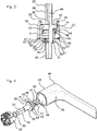
- a lock according to the invention mounted on an opening 32 comprises a handle 48 for manipulating a bolt of the opening 32 to open or close the opening 32.
- the opening 32 comprises a front wall 34 having two opposite faces, a first face 36 , said inner face, oriented towards an inner side of the opening 32, and a second face 35, said outer face, oriented towards an outer side of the opening 32.
- the inner face 36 of the wall 34 defines a hollow cavity 60 of the opening.
- the operating handle 48 is positioned on the outside of the opening 32 against the outer face 35 and facing an orifice 33 passing through the wall 34 of the opening 32, a portion of the square 37 of the lock extending to through the hole 33.
- the lock In order to manipulate the bolt of the opening 32, the lock also comprises a square 37 adapted to transmit a rotational movement of the handle 48, the rotational movement for manipulating the bolt of the opening 32. More particularly, the square 37 of lock is a rod, for example metal.
- the square 37 is formed of an end, said end 38 guided, adapted to be integrally assembled in rotation with the handle 48 of operation.
- the end 38 guided is preferably of parallelepiped shape.
- the square 37 is also formed of an end, said end 39 of transmission, adapted to be assembled with a mechanism for manipulating the bolt of the opening 32.
- the transmission end 39 is advantageously of parallelepipedal shape.
- the square 37 of the lock is assembled to the opening 32 by a base 20 according to the invention, shown in FIGS. Figures 1 to 5 .
- the base 20 has a main body 21 comprising a bore 59 adapted to be traversed by the square 37 of lock.
- the bore 59 of the base 20 and facing the opening 33 of the opening 32 so that the square 37 can pass through the bore 59 of the 20 and the opening 33 of the opening 32 to reach an operating mechanism placed in the hollow cavity 60 of the opening 32 and for manipulating the bolt of the opening 32.
- the diameter of the bore of the main body 21 of the base 20 is smaller than the diameter of the orifice 33 of the opening 32.
- the base 20 In order to assemble the square 37 to the opening 32, the base 20 has a face, called the hooking face 58, forming the top of the base 20.
- the hooking face 58 makes it possible to obtain a bearing of abutment in order to keep the square 37 assembled to the base 20 and prevent any translational movement of the square 37.
- the base 20 also has a face, said face 57 of embedding, towards the underside of the base 20, and therefore opposed to the face 58 of attachment, and to assemble the base 20 to the opening 32.
- the base 20 is preferably made of a synthetic polymer material.
- the synthetic polymer material has a low coefficient of friction and a coefficient of elasticity for slightly deforming the base 20 during assembly and disassembly of the lock.
- the square 37 has between its two ends a tubular assembly section adapted to be positioned in the base 20.
- This section comprises a cylindrical portion, said thin portion, and a cylindrical collar 41 extending transversely around and projecting from the lower part, the collar 41 and the thin part being coaxial.
- the hooking face 58 of the base 20 comprises two fingers, said holding fingers 23, each extending projecting from the main body 21 towards the top of the base 20.
- Each holding finger 23 has a front face, called the outer face, extending the periphery of the main body 21.
- each retaining finger 23 protrudes from the main body 21 to an end having a hook 30 on one side, said inner face, opposite to the outer face of the retaining finger 23.
- the holding fingers 23 are positioned so as to be parallel and facing one another.
- the face internal of each retaining finger 23 has in transverse cross section a radius of curvature similar to that of the collar 41 of the square 37 of the lock.
- the retaining fingers 23 are flexible in order to be able to spread them to fit the collar 41 of the square 37 in the base 20.
- the holding fingers 23 have a radial space at rest (ie its position before deformation in bending), determined by the distance between the hooks 30, less than the diameter of the collar 41, the hooks 30 are positioned on a face 43, called the holding face, of the collar 41.
- the distance between the face 58 of hooking of the main body 21 and each hook 30 is at least substantially equal to the height of the collar 41 so as to prevent any translation movement of the square 37 when the collar 41 is fitted into the base 20.
- a face 42, said bearing face, opposite the face 43 for holding the collar 41 is positioned against the face 58 of attachment of the base 20.
- the hook 30 of each finger 23 of maintenance has a bis water, oriented towards the top of the base 20, allowing to easily spread the holding fingers 23 by fitting the collar 41 in the base 20.
- the hooking face 58 also comprises two guide portions 25 making it possible to split the rotation of the square 37. More particularly, each guide portion of the hooking face 58 extends the periphery of the main body 21 so that it each extends in projection from the main body 21 towards the top of the base 20. More particularly, these two guide portions are placed facing one another on an axis orthogonal to an axis passing in the center of the two. holding fingers 23. These two guide portions each have a protrusion, said tooth 63, adapted to cooperate with four grooves 62 present on the cylindrical face of the collar 41 of the square 37. In addition, the teeth 63 are placed so as to be diametrically opposed and facing each other. one from the other.
- the grooves 62 are placed at 90 ° to each other so that the rotation of the square 37 is blocked every 90 ° when the teeth of the guide portions are placed in diametrically opposite grooves 62 of the collar 41 of the square 37.
- the teeth are also adapted to emerge from the grooves 62 when a rotation of the square 37 is performed.
- a resilient shim 55 of diameter less than the distance between the holding fingers 23, is placed on the main body 21 of the base 20 between the fingers 23 for holding the base 20.
- the elastic shim 55 has an orifice of diameter greater than or equal to the diameter of the bore of the main body of the base so that it can be traversed by the square 37.
- Such an elastic shim 55 may be used when the distance between the main body 21 of the base 20 and the hook 30 23 of the holding finger is greater than the thickness of the collar 41 so as to have a clearance between the main body 21 of the base 20 and the bearing face 42 of the collar 41 of the square 37. Such a game may be necessary to make sure that the collar 41 of the square 37 t be placed between the hooks 30 of the holding fingers 23 and the main body 21.
- the deformation of the elastic shim 55 makes it possible to adapt the thickness of the elastic shim 55 so as to eliminate the play when the collar 41 is placed between the hooks 30 of the holding fingers 23 and the main body 21 so that a such play is not felt by a person handling the handle.
- the face 57 of embedding of the base 20 comprises two fingers, said fingers 22 of recess, each extending projecting from the main body 21 towards the underside of the base 20.
- Each finger has a first end face, so-called internal face, axially extending the bore 59 of the base 20.
- each flange 22 extends projecting from the main body 21 to an end having a hook 29 transversely projecting from a second face frontal, said external face, opposite to the inner face. More particularly the recessing fingers 22 are positioned so as to be parallel and facing one another.
- the inner face of each flush finger 22 has in transverse cross section a radius of curvature similar to that of the section of the bore 59 of the base 20 that it extends.
- each flush finger 22 also has in cross section a radius of curvature similar to that of the section of the bore 59 of the base 20 that it extends. Moreover, the distance between the external faces of flush fingers 22 is smaller than the diameter of the opening 33 of the opening 32. In addition, the flush-fitting fingers 22 have a radial space at rest, determined by the distance between the hooks 29, which is greater than the diameter of the flange. orifice 33 of the opening 32.
- the recessing fingers 22 are flexible in order to be able to bring them closer to fit the base 20 in the opening 33 of the opening 32.
- the recessing fingers 22 deviate so as to resume at least substantially their rest position, that is to say a position in which the finger is not flexed.
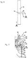
- a locking surface 61, directed towards the top of the base 20, of each hook 29 of each mounting finger 22 is positioned against the inner face 36 of the wall 34 of the opening 32 around the orifice 33 of the opening 32 in the hollow cavity 60.
- the locking surface 61 is arranged to be placed, while the main body 21 of the base 20 is in abutment against the outer face of the front wall 34 of the opening 32, against an edge of the orifice 33 through the front wall 34 of the opening on the inner face 36 of the front wall 34.
- each flush-fitting finger 22 has a bevel, oriented towards the bottom of the base 20, making it possible to easily bring the flush-fitting fingers 22 together by fitting the base 20 into the hole 33 of the flange. opening 32.
- each hook 29 of each flush-fitting finger 22 is angled in order to facilitate the approaching of the flush-fitting fingers 22 by withdrawing the base 20 from the opening 33 of the opening 32.
- this locking surface 61 allows the hook 29 to adapt to walls 34 of the opening 32 of different thickness as shown in FIG. figure 7 .
- each flush finger 22 comprises a deformable structure on its inner face, facing the square 37 of the lock, which can be formed by ribs 31 and to adapt the base to the thickness of a wall 34 front opening 32.
- the distance between the fingers 22 of the flange of the base 20 varies so that the insertion of the square 37 may be more or less easy or impossible when the gap between the flush fingers 22 is too narrow.
- the ribs 31 facilitate the insertion of the square 37 by being compressed by the square 37 so as to adapt to the diameter of the thin portion of the assembly section of the square 37.
- the mounting face 57 also comprises projections 27 of contact projecting from the main body 21 of the base 20 towards the bottom of the piece.
- These contact projections 27 have a cylindrical shape of revolution. More particularly, these contact protrusions 27 have a diameter of between 1 mm and 4 mm, for example of the order of 2.5 mm and a height of between 0 mm and 3 mm, for example of the order of 0, 8 mm.
- the projections 27 of contact are arranged circularly on the face 57 of embedding of the base 20.
- the distance between the projections 27 of contact and the hooks 29 of the fingers 22 of embedding makes it possible to define a range of thicknesses wall 34 opening 32 for which the base is adapted.
- the modification of the height of the contact protrusions 27 makes it possible to adapt a base 20 to all wall thicknesses 34 of the opening 32.
- the recess face 57 also comprises two guide portions 24 extending the bore so that they each extend in projection from the main body 21 towards the underside of the base 20. More particularly, these two guide portions 24 are placed opposite one another on an axis orthogonal to an axis passing in the center of the two fingers 22 of embedding. In addition, the two portions 24 for guiding the face 57 of embedding have a radius of curvature identical to that of the section of the bore 59 of the base 20 that it extends. The two portions also have a height lower than that of the fingers 22 of embedding. These guide portions 24 serve to guide the square 37 of the lock in rotation and to prevent any contact between the square 37 of the lock and the front wall 34 of the opening 32.
- the recess face 57 also comprises two pins 26 projecting from the main body 21 towards the bottom of the base 20.
- Each pin 26 is adapted to be placed in an opening 33 of the opening 32.
- the pins 26 are inserted into the openings of the wall 34 of the opening 32 placed around the opening 33 of the opening 32 they prevent any rotation of the base 20 relative to the opening 32.
- the two pins 26 are positioned opposite one another on the axis on which are placed the two portions 24 guiding the face 57 of embedding.
- the dowels 26 thus make it possible to prevent the square 37 from rotating the base 20 with which it is assembled when the latter is assembled to the front wall 34 of the opening 32.
- the recess face 57 also comprises recesses 28 on the lower face of the base 20.
- the recesses 28 make it possible to unhook the base 20 easily from the opening 32 to which it is assembled, with the help of a lever such as a flat-tipped screwdriver for example.
- the handle 48 has an end 53, said operating end, for handling the handle 48 and an end 54, said guide end, integrally rotated to the square 37.
- the end 54 guide comprises a cavity, said receiving cavity 49, in which are placed the end 38 guided and the collar 41 of the square 37 and the fingers 23 for holding the base 20.
- the cavity 49 for receiving the operating handle 48 comprises a first bore 50 opening towards the outside of the operating handle 48 and a second bore 51, having a section smaller than that of the first bore 50, opening onto the first bore 50, the two bores extending along parallel axes.
- the end 38 guided the square 37 is embedded in the second bore 51.
- the square 37 is integrally assembled with the handle 48 maneuvering.
- the flange 41 and the fingers 23 for holding the base 20 are positioned in the first bore 50.
- said receiving cavity 49 has a shoulder between the first and the second bore 51. This shoulder is spaced from the face 43 for holding the collar 41 of the square 37 at a greater distance. or equal to a length of the hook 30 of the fingers 23 for holding the base 20 so that the hook 30 of each retaining finger 23 can be positioned between the holding face 43 and the shoulder of the receiving cavity 49.
- the square 37 can be held at the handle 48 while being able to be mounted and disassembled easily handle 48 maneuvering.
- the square 37 is introduced into the second bore 51 of the cavity 49 for receiving the operating handle 48, the second bore 51 having a main section sufficiently greater than that of the end 38 guided by the square 37 so that the square 37 can be easily inserted and removed from the second bore 51 of the receiving cavity 49.
- an assembly device makes it possible to prevent any translational movement of the square 37 with respect to the operating handle 48 in order to keep the square 37 assembled to the operating handle 48.
- the assembly device comprises a pin 47, placed in a transverse blind bore 44 of the end 38 guided by the square 37, with elastic return formed by a spring 46.
- a first end of the spring 46 is assembled at the bottom of the the blind bore 44 and a second end is assembled to the pin 47.
- the spring 46 exerts a transverse force on the pin 47 to place the pin 47 projecting from the square 37 so that it is introduced into a bore of the operating handle 48, said assembly bore 52, having an end opening on the second bore 51 of the receiving cavity 49 and orthogonal to the latter when the end 38 guided by the square 37 is introduced into this second bore 51.
- the assembly bore 52 has a second end opening outwardly from the handle 48.
- the assembly device is adapted so that the pin 47 enters the bore 44 of the end 38 guided by the square 37 when a thrust force, opposite and greater than the force exerted by the spring 46 on the pin 47, is exerted on the pin 47.
- the receiving cavity 49 has at least one locking surface 56 in the first bore 50 adapted to be in contact with at least one retaining finger 23 when the handle 48 is assembled to the square 37 of lock maintained by the Such a locking surface 56 thus makes it possible to prevent any bending movement of the holding finger 23 against which it is positioned.
- the locking surface 56 thus prevents the square 37 from being withdrawn from the base 20.
- the mounting of a lock according to the invention comprises a first step in which the base 20 is engaged in the opening 33 of the opening 32. More particularly, the interlocking consists in introducing the two fingers 22 of embedding the base 20 in the opening 33 of the opening 32 by exerting a thrust force on the base 20 towards the inner side of the opening 32 to bring by bending the two fingers 22 of embedding the base 20 so that the distance between the hooks 29 is greater than the diameter of the opening 33 of the opening 32.
- the bearing 61 of the hooks 29 22 nesting fingers is positioned against the inner face 36 of the wall 34 of the opening 32.
- the base 20 is assembled to the opening 32 but can still be removed from the orifice 33 by exerting a pulling force towards the outer side of the sash 32 making it possible to move closer to flexion the fingers 22 of embedding so that the distance between the hooks 29 is less than the diameter of the opening 33 of the opening 32, the hooks 29 then no longer in contact with the inner face 36 of the wall 34 of the opening 32.
- a resilient shim 55 can be placed on the face 58 of attachment of the main body 21.
- the square 37 of lock is introduced into the bore of the main body 21 of the base 20 until its collar 41 comes to fit between the main body 21 of the base 20 and the hooks 30 of the fingers 23 of maintenance. More particularly, a thrust force is exerted on the square 37 towards the inner side of the opening 32 so that the collar 41 flexibly deflects the holding fingers 23 of the base 20 so that the distance between the hooks 30 is greater than the diameter of the collar 41 to introduce the collar 41 between the main body 21 of the base 20 and the hook 30 of each holding finger 23.
- the hooks 30 are then positioned against the face 43 for holding the collar 41 thus making it possible to maintain the square 37 in the base 20 and to eliminate any translation movement of the square 37 with respect to the base 20 and to the opening 32.
- the introduction of the square 37 in the base 20 makes it possible to position the thin portion of the assembly section of the square 37 against the mounting fingers 22 and thus to eliminate any bending of the fingers 22 of embedding the base 20 thus preventing the base 20 from withdrawing from the opening 33 of the opening 32 when a pulling force towards the outer side of the opening 32 is exerted on it.
- these two steps are sufficient to assemble the handle 48 to the opening maneuver 32.
- the handle 48 is engaged on the square 37 so that the end 38 guided and the collar 41 of the square 37 and the fingers 23 for holding the base 20 come s' introducing into the cavity 49 for receiving the operating handle 48. More particularly, the end 38 guided by the square 37 is introduced into the second bore 51 of the receiving cavity 49 while the collar 41 of the square 37 and the holding fingers 23 of the base 20 are positioned in the first bore 50 of the receiving cavity 49.
- the end 38 guided square 37 is introduced into the second bore 51 so that the pin 47 is oriented towards the bore 52 assembly of the handle 48 maneuvering.
- the handle 48 can not be disassembled from the square 37 by exerting on it a tensile force towards the outer side of the opening 32.
- the holding fingers 23 of the base 20 are positioned between the collar 41 of the square 37 and the bearing surface 56 of the cavity 48 of the handle 48. maneuvering so that any bending movement of the holding fingers 23 is neutralized, thus preventing the square 37 from being withdrawn from the base 20 by exerting on it a tensile force towards the outer side of the opening 32.
- the disassembly of the lock comprises a first step in which it exerts a thrust force on the pin 47 opposite the the force exerted by the spring 46 on the latter in order to fit the pin 47 into the bore 44 of the end 38 guided by the square 37.
- a thrust force for example, it is possible to exert such a thrust force by introducing a rod, such as an Allen key, in the bore 52 assembly from the outside of the handle, until pressing the pin 47 so as to enter the bore 44 of the end 38 guided the square 37
- the handle 48 can be removed from the square 37 of the lock.
- removing the handle 48 for maneuver also frees the fingers 23 to hold their embrace, the holding fingers 23 no longer in contact with the bearing surface 56 of the cavity of the handle 48 to maneuver, so that the holding fingers 23 can be bent.
- the disassembly of a lock according to the invention also comprises a step in which the holding fingers 23 are moved away so that the distance between the hooks 30 is greater than the diameter of the collar 41 in order to remove the collar 41 from the base 20. Furthermore, removing the square 37 from the base 20 also frees the fingers 22 of embedding their embrace, the fingers 22 of installation no longer in contact with the square 37, so that the fingers 22 of embedment can be bent.
- the base 20 can be removed from the opening 33 of the opening 32 by exerting a tensile force towards the outer side of the opening 32 in order to move by bending the fingers 22 of embedding the base 20 so that the distance between the hooks 29 is smaller than the diameter of the orifice 33.
Abstract
L'invention concerne une embase de montage d'un carré (37) de serrure sur une paroi (34) frontale d'un ouvrant (32), cette paroi (34) frontale présentant une face (36) interne et un orifice (33) traversant, l'embase comprenant : - un corps (21) principal présentant un alésage (59) apte à recevoir un carré (37) de serrure, - au moins un doigt flexible, dit doigt (22) d'encastrement, présentant une portée (61) de blocage agencée pour pouvoir être placée au moins en partie contre la face (36) interne de l'ouvrant (32), caractérisé en ce qu'elle comprend en outre au moins un doigt flexible, dit doigt (23) de maintien, présentant une portée (61) de blocage agencée pour pouvoir être placée au moins en partie contre une face (43), dite face de maintien, d'un collet (41) d'un carré (37) de serrure. L'invention s'étend également à une serrure comprenant une telle embase et un procédé de montage de cette serrure.The invention relates to a base for mounting a lock square (37) on a front wall (34) of an opening (32), this front wall (34) having an internal face (36) and an orifice (33). ), the base comprising: - a main body (21) having a bore (59) adapted to receive a square (37) lock, - At least one flexible finger, said finger (22) for embedding, having a locking surface (61) arranged to be placed at least partly against the face (36) of the inner opening (32), characterized in that it further comprises at least one flexible finger, said finger (23) holding, having a locking surface (61) arranged to be placed at least partly against a face (43), said face of maintaining, a collar (41) of a square (37) lock. The invention also extends to a lock comprising such a base and a method of mounting this lock.
Description
L'invention concerne une embase de montage d'un carré de serrure d'ouvrant, une serrure d'ouvrant comprenant une telle embase et un procédé de montage d'une serrure sur une paroi frontale d'un ouvrant, notamment sur un profilé creux d'ouvrant.The invention relates to a mounting base of a door lock square, a door lock comprising such a base and a method of mounting a lock on a front wall of an opening, in particular on a hollow profile. opening of.
Dans tout le texte, le terme « ouvrant » désigne toute partie d'un ouvrage de menuiserie telle qu'une porte, une fenêtre, un tiroir... mobile par rapport à un dormant fixe de l'ouvrage de menuiserie. En particulier, l'invention concerne les ouvrants à châssis présentant un profilé creux, métallique ou en matière synthétique par exemple.Throughout the text, the term "opening" designates any part of a carpentry work such as a door, a window, a drawer ... movable relative to a fixed frame of the carpentry work. In particular, the invention relates to frame openings having a hollow section, metal or synthetic material for example.
En outre, dans tout le texte on désigne par le terme « flexibilité » l'aptitude d'un corps à se déformer élastiquement en flexion (sous l'effet d'un effort appliqué perpendiculairement à sa longueur).In addition, throughout the text is designated by the term "flexibility" the ability of a body to deform elastically bending (under the effect of a force applied perpendicular to its length).
On connaît déjà de nombreuses serrures comprenant une poignée de manoeuvre rotative permettant de déplacer un pêne de la serrure pour la verrouiller ou la déverrouiller, en vue de fermer ou, respectivement, d'ouvrir l'ouvrant. Une telle poignée de manoeuvre permet d'engager le pêne dans une gâche du châssis, afin de verrouiller la serrure et l'ouvrant en position fermée ; ou de dégager le pêne à l'extérieur de la gâche afin de déverrouiller la serrure et d'ouvrir l'ouvrant. Le déplacement du pêne résulte d'un mouvement de rotation de la poignée de manoeuvre. La poignée de manoeuvre est généralement assemblée solidaire en rotation d'un « carré » (dans tout le texte, le terme « carré » désigne un arbre à section droite transversale non symétrique de révolution -notamment carrée-d'un mécanisme de serrure et destiné à recevoir une poignée de manoeuvre rotative) d'un mécanisme de transmission permettant de transformer le mouvement de rotation de la poignée de manoeuvre en un mouvement approprié de déplacement du pêne. Une telle poignée de manoeuvre est aussi en général prévue pour pouvoir être utilisée pour déplacer l'ouvrant lui-même entre ses positions ouverte et fermée.Numerous locks are already known comprising a rotary operating handle for moving a bolt of the lock to lock or unlock it, in order to close or, respectively, to open the opening. Such a maneuvering handle makes it possible to engage the bolt in a striker of the frame, in order to lock the lock and the opening in closed position; or to release the bolt outside the strike in order to unlock the lock and open the opening. The movement of the bolt results from a rotational movement of the operating handle. The operating handle is generally assembled in rotation with a "square" (throughout the text, the term "square" designates a shaft cross-section non-symmetrical revolution-especially square-of a lock mechanism and intended receiving a rotary operating handle) of a transmission mechanism for transforming the rotational movement of the operating handle into an appropriate movement of movement of the bolt. Such a maneuvering handle is also generally provided to be used to move the opening itself between its open and closed positions.
En outre, le carré et la poignée de manoeuvre sont préférablement assemblés à l'ouvrant selon une liaison pivot non glissant afin d'éliminer tout mouvement de translation du carré et de la poignée de manoeuvre par rapport à l'ouvrant.In addition, the square and the operating handle are preferably assembled to the opening in a non-sliding pivot connection so eliminate any translational movement of the square and the operating handle relative to the opening.
La poignée de manoeuvre et/ou le carré sont généralement fixés à la paroi frontale de l'ouvrant par une embase.The operating handle and / or the square are generally fixed to the front wall of the opening by a base.
Le montage d'une telle serrure, et plus particulièrement l'assemblage de la plaque de support et de la poignée de manoeuvre au profilé, nécessite donc d'utiliser de nombreuses vis et d'avoir à disposition un tournevis. Le montage d'une telle serrure est donc relativement long et coûteux. En outre, le montage d'une telle serrure est complexe car il nécessite de maintenir l'embase contre le profilé de l'ouvrant afin de pouvoir la visser.The mounting of such a lock, and more particularly the assembly of the support plate and the operating handle to the profile, therefore requires the use of many screws and to have available a screwdriver. The mounting of such a lock is therefore relatively long and expensive. In addition, the mounting of such a lock is complex because it requires to maintain the base against the profile of the opening so as to screw it.
L'invention vise à pallier ces inconvénients.The invention aims to overcome these disadvantages.
Elle vise donc à proposer une serrure pouvant être montée et démontée sur un profilé creux d'ouvrant rapidement, facilement et économiquement.It therefore aims to provide a lock that can be mounted and dismantled on a hollow profile opening quickly, easily and economically.
L'invention vise en particulier à proposer une embase de montage d'un carré de serrure d'ouvrant adaptée pour être montée rapidement, facilement et économiquement sur un profilé creux d'ouvrant.The invention aims in particular to provide a mounting base of a sash lock square adapted to be mounted quickly, easily and economically on a hollow profile opening.
Elle vise en particulier à proposer une embase permettant de monter un carré et une poignée de manoeuvre sans utiliser d'outils.It aims in particular to provide a base for mounting a square and an operating handle without using tools.
Pour ce faire, l'invention concerne une embase de montage d'un carré de serrure sur une paroi frontale d'un ouvrant, cette paroi frontale présentant une face interne délimitant une cavité creuse de l'ouvrant et un orifice traversant, l'embase comprenant :
- un corps principal présentant un alésage apte à recevoir un carré de serrure,
- des moyens de fixation à l'orifice traversant de la paroi frontale de l'ouvrant, les moyens de fixation comprennent au moins un doigt flexible, dit doigt d'encastrement, s'étendant en saillie du corps principal selon une direction longitudinale, comprenant :
- o au moins un crochet :
- ▪ s'étendant en saillie transversalement à la direction longitudinale,
- ▪ agencé pour pouvoir être introduit dans l'orifice de la paroi frontale de l'ouvrant depuis une face externe de ladite paroi frontale de l'ouvrant, opposée à ladite face interne,
- ▪ présentant une portée de blocage agencée pour pouvoir être placée, alors que le corps principal de l'embase est en appui contre la face externe de la paroi frontale de l'ouvrant, au moins en partie contre la face interne de la paroi frontale de l'ouvrant,
- s'étendant à partir du corps principal,
- comprenant au moins un crochet présentant une portée de blocage agencée pour pouvoir être placée au moins en partie contre une face, dite face de maintien, d'un collet d'un carré de serrure pour assembler et bloquer en translation le carré de serrure au corps principal de l'embase tout en autorisant la rotation du carré de serrure dans l'alésage du corps principal de l'embase.
- o au moins un crochet :
- a main body having a bore adapted to receive a lock square,
- fastening means to the through hole of the front wall of the opening, the fixing means comprise at least one flexible finger, said fitting finger, projecting from the main body in a longitudinal direction, comprising:
- o at least one hook:
- Extending projecting transversely to the longitudinal direction,
- Arranged to be introduced into the orifice of the front wall of the opening from an outer face of said front wall of the opening, opposite to said inner face,
- ▪ Having a locking surface arranged to be placed, while the main body of the base is in abutment against the outer face of the front wall of the opening, at least partially against the inner face of the front wall of opening,
- extending from the main body,
- comprising at least one hook having a locking surface arranged to be placed at least partly against a face, said holding face, of a collar of a lock square to assemble and lock in translation the lock square to the body the base while allowing rotation of the lock square in the bore of the main body of the base.
- o at least one hook:
Une embase selon l'invention peut être placée contre une face externe d'une paroi frontale d'un ouvrant afin de maintenir un carré et une poignée de manoeuvre de serrure à l'ouvrant.A base according to the invention can be placed against an outer face of a front wall of an opening to maintain a square and a lock maneuvering handle to the opening.
La flexibilité du doigt d'encastrement permet donc de fléchir le doigt d'encastrement, de sorte que l'extrémité du doigt d'encastrement se rapproche d'un axe principal de l'alésage du corps principal, pour que son crochet puisse être introduit dans un orifice d'une paroi frontale d'ouvrant. Ainsi, l'embase peut être emboîtée dans une paroi frontale de l'ouvrant.The flexibility of the flush finger thus allows the flush finger to be flexed, so that the end of the flush finger approaches a main axis of the bore of the main body, so that its hook can be introduced. in an opening of a front wall opening. Thus, the base can be nested in a front wall of the opening.
La flexibilité du doigt d'encastrement permet également au doigt d'encastrement de reprendre au moins sensiblement sa position de repos, c'est-à-dire une position dans laquelle le doigt d'encastrement n'est pas fléchi, lorsqu'il est introduit dans un orifice d'une paroi frontale d'ouvrant. Dans une telle position, le crochet peut se placer contre la face interne de la paroi de l'ouvrant. Le crochet du doigt d'encastrement permet donc de maintenir l'embase emboîtée dans l'ouvrant.The flexibility of the flush finger also allows the flush finger to at least substantially resume its rest position, that is to say a position in which the flush finger is not flexed, when it is introduced into a hole of a front wall opening. In such a position, the hook can be placed against the inner face of the wall of the opening. The hook of the flush finger thus allows to maintain the base fitted into the opening.
Dans certains modes de réalisation avantageux, l'embase comprend deux doigts d'encastrement parallèles positionnés en regard autour de l'alésage du corps principal de l'embase.In some advantageous embodiments, the base comprises two parallel mounting fingers positioned facing around the bore of the main body of the base.
Ainsi, une telle embase peut être assemblée à une paroi frontale d'un ouvrant sans utiliser d'outils.Thus, such a base can be assembled to a front wall of an opening without using tools.
En outre, une telle embase est adaptée pour être assemblée à n'importe quel ouvrant.In addition, such a base is adapted to be assembled to any opening.
Par ailleurs, chaque doigt de maintien permet d'assembler et de bloquer en translation un carré de serrure au corps principal de l'embase tout en autorisant la rotation du carré de serrure dans l'alésage du corps principal de l'embase.Furthermore, each retaining finger can assemble and lock in translation a lock square to the main body of the base while allowing the rotation of the lock square in the bore of the main body of the base.
Plus particulièrement, le carré comprend une tige principale et un collet, ce dernier étant une portion du carré s'étendant transversalement autour et en saillie de la tige principale.More particularly, the square comprises a main stem and a collar, the latter being a portion of the square extending transversely around and projecting from the main stem.
Le corps principal de l'embase présente donc une face, dite face d'accrochage, formant le dessus de l'embase. La face d'accrochage permet d'obtenir un palier de butée afin de maintenir assemblé le carré à l'embase et d'empêcher tout mouvement de translation du carré en maintenant le collet du carré entre le palier de butée et la portée de blocage du crochet de chaque doigt de maintien. Le corps principal de l'embase présente donc également une face, dite face d'encastrement, vers le dessous de l'embase, et donc opposée à la face d'accrochage, et permettant d'assembler l'embase à la paroi frontale de l'ouvrant.The main body of the base thus has a face, said attachment face, forming the top of the base. The attachment face makes it possible to obtain an abutment bearing in order to keep the square joined to the base and to prevent any translation movement of the square by holding the collar of the square between the thrust bearing and the locking surface of the square. crochet each finger of maintenance. The main body of the base thus also has a face, called the embedding face, towards the underside of the base, and therefore opposite to the attachment face, and enabling the base to be assembled to the front wall of the base. opening.
Ainsi, chaque doigt de maintien s'étend à l'opposé de chaque doigt d'encastrement à partir du corps principal de l'embase.Thus, each retaining finger extends opposite to each flush finger from the main body of the base.
Une telle embase peut ainsi être montée ou démontée de la porte en permettant à la personne montant ou démontant l'embase de rester du même côté de l'ouvrant.Such a base can thus be mounted or removed from the door by allowing the person mounting or dismounting the base to remain on the same side of the opening.
En effet, chaque doigt de maintien est facilement accessible car placé à l'extérieur de l'ouvrant et du côté de la face externe de l'ouvrant sur laquelle peut être montée une poignée de manoeuvre.Indeed, each retaining finger is easily accessible because placed outside the opening and on the side of the outer face of the opening on which can be mounted a handle.
La flexibilité de chaque doigt de maintien permet de fléchir le doigt de maintien, de façon à augmenter la distance entre ce doigt de maintien et l'axe principal de l'alésage de l'embase, pour que le collet d'un carré de serrure puisse être introduit entre le crochet du doigt de maintien et le corps principal de l'embase. En outre, lorsqu'un collet de carré est introduit entre le crochet et le corps principal de l'embase, chaque doigt de maintien reprend sa position de repos, c'est-à-dire la position dans laquelle ce doigt de maintien n'est pas fléchi. Dans cette position, le crochet de chaque doigt de maintien vient se placer contre la face de maintien du collet du carré.The flexibility of each retaining finger makes it possible to bend the retaining finger, so as to increase the distance between this retaining finger and the main axis of the bore of the base, so that the collar of a lock square can be introduced between the hook of the holding finger and the main body of the base. In addition, when a square collar is introduced between the hook and the main body of the base, each retaining finger resumes its rest position, that is to say the position in which the retaining finger n ' is not bent. In this position, the hook of each retaining finger is placed against the retaining face of the collar of the square.
Dans certains modes de réalisation avantageux, l'embase comprend deux doigts de maintien parallèles positionnés en regard autour de l'alésage du corps principal de l'embase.In some advantageous embodiments, the base comprises two parallel holding fingers positioned facing around the bore of the main body of the base.
Ainsi, un carré de serrure peut être assemblé facilement et rapidement à une embase selon l'invention.Thus, a lock square can be assembled easily and quickly to a base according to the invention.
Avantageusement et selon l'invention, ladite portée de blocage d'un crochet d'un doigt d'encastrement est orientée en biais en formant un angle obtus par rapport à la direction longitudinale du doigt d'encastrement.Advantageously and according to the invention, said locking surface of a hook of a fitting finger is oriented obliquely at an obtuse angle with respect to the longitudinal direction of the fitting finger.
Ladite portée de blocage orientée en biais permet ainsi à l'embase de s'adapter à différentes épaisseurs d'une paroi frontale d'un d'ouvrant entre sa face extérieure et sa face intérieure. L'embase peut donc être assemblée à un ouvrant indépendamment de l'épaisseur de sa paroi frontale.Said biased locking surface thus allows the base to adapt to different thicknesses of a front wall of an opening leaf. between its outer face and its inner face. The base can be assembled to an opening regardless of the thickness of its front wall.
Ainsi, la portée de blocage est agencée pour pouvoir être placée, alors que le corps principal de l'embase est en appui contre la face externe de la paroi frontale de l'ouvrant, contre une arête de l'orifice traversant de la paroi frontale de l'ouvrant sur la face interne de la paroi frontaleThus, the locking surface is arranged to be placed, while the main body of the base is in abutment against the outer face of the front wall of the opening, against an edge of the through orifice of the front wall. opening on the inner face of the front wall
En outre, ladite portée de blocage orientée en biais permet également, après assemblage de l'embase sur la paroi frontale, l'extraction du doigt d'encastrement hors de l'orifice sous l'effet d'un effort de traction exercé sur le corps principal tendant à éloigner l'embase de la paroi frontale.In addition, said biased locking surface also allows, after assembly of the base on the front wall, the extraction of the embedding finger from the orifice under the effect of a tensile force exerted on the main body tending to move the base of the front wall.
Par ailleurs, un doigt d'encastrement présente une structure déformable au moins transversalement en compression sur une face frontale opposée au crochet. Plus particulièrement, la déformation peut être plastique ou bien élastique. La structure déformable permet d'adapter l'embase à l'épaisseur d'une paroi frontale d'ouvrant. En effet, selon l'épaisseur de la paroi frontale de l'ouvrant, l'écart entre les doigts d'encastrement de l'embase varie de sorte que l'insertion du carré peut être plus ou moins facile voire impossible lorsque l'écart entre les doigts d'encastrement est trop étroit. Les nervures permettent de faciliter l'insertion du carré en étant compressées par le carré de façon à s'adapter au diamètre de la partie mince de la section d'assemblage du carré. Plus particulièrement, la structure déformable peut être formée par des nervures s'étendant en saillie transversalement de la face frontale opposée au crochet.Furthermore, an embedding finger has a deformable structure at least transversely in compression on a front face opposite the hook. More particularly, the deformation can be plastic or elastic. The deformable structure makes it possible to adapt the base to the thickness of a front opening wall. Indeed, depending on the thickness of the front wall of the opening, the gap between the recessing fingers of the base varies so that the insertion of the square can be more or less easy or impossible when the gap between the flush fingers is too narrow. The ribs facilitate insertion of the square by being compressed by the square so as to adapt to the diameter of the thin portion of the assembly section of the square. More particularly, the deformable structure may be formed by ribs projecting transversely from the end face opposite the hook.
Par ailleurs, de préférence, la face d'accrochage du corps principal de l'embase est apte à être en contact d'une face, dite face de repos, du collet du carré de serrure, opposée à sa face de maintien, la face d'accrochage étant espacée d'un crochet de chaque doigt de maintien d'une distance au moins sensiblement égale à la distance entre la face de maintien et la face de repos du collet.Furthermore, preferably, the attachment face of the main body of the base is adapted to be in contact with a face, said face of rest, the collar of the lock square, opposite its holding face, the face hooking being spaced from a hook of each holding finger a distance at least substantially equal to the distance between the holding face and the face of repose of the collar.
Ainsi, une embase selon l'invention permet d'empêcher tout mouvement transversal d'un carré de serrure comprenant un collet par rapport à l'embase.Thus, a base according to the invention makes it possible to prevent any transverse movement of a lock square comprising a collar relative to the base.
Dans certains modes de réalisation avantageux de l'invention, le corps principal de l'embase comprend au moins une cheville agencée pour pouvoir être introduite dans une lumière de ladite paroi frontale pour bloquer l'embase en rotation par rapport à cette paroi frontale lorsque l'embase est assemblée à la paroi frontale.In certain advantageous embodiments of the invention, the main body of the base comprises at least one pin arranged to be introduced into a slot of said front wall to lock the base in rotation relative to this front wall when the base is assembled to the front wall.
La cheville permet donc d'éviter qu'un carré de serrure entraîne en rotation une embase selon l'invention avec laquelle il est assemblé lorsque cette dernière est assemblée à une paroi frontale d'ouvrant.The anchor thus makes it possible to prevent a lock square from rotating a base according to the invention with which it is assembled when the latter is assembled to a front wall of an opening.
L'invention s'étend également à une serrure d'ouvrant destinée à être assemblée à une paroi frontale d'un ouvrant, cette paroi frontale présentant une face interne délimitant une cavité creuse de l'ouvrant et un orifice traversant, la serrure comprenant :
- un mécanisme comprenant un carré rotatif,
- une poignée de manoeuvre montée sur le carré de façon à être solidaire en rotation de ce dernier,
- a mechanism comprising a rotating square,
- an operating handle mounted on the square so as to be integral in rotation with the latter,
Plus particulièrement, le carré de la serrure et la poignée de manoeuvre peuvent former une unique pièce ou bien deux pièces séparées.More particularly, the square of the lock and the operating handle can form a single piece or two separate pieces.
En outre, l'alésage de l'embase permet de guider en rotation le carré de la serrure afin de manipuler un pêne de l'ouvrant.In addition, the bore of the base rotates the square of the lock to manipulate a bolt of the opening.
En outre, avantageusement et selon l'invention, chaque doigt d'encastrement de l'embase est agencé de telle sorte que lorsque le carré est introduit dans l'alésage du corps principal de l'embase, le carré empêche au moins en partie toute flexion de chaque doigt d'encastrement dans le sens d'un désengagement de chaque crochet par rapport à la face interne de la paroi frontale de l'ouvrant, l'embase étant alors inamovible de la paroi frontale.In addition, advantageously and according to the invention, each recessing finger of the base is arranged such that when the square is inserted into the bore of the main body of the base, the square prevents at least partly all bending of each flush finger in the direction of disengagement of each hook relative to the inner face of the front wall of the opening, the base then being irremovable from the front wall.
Plus particulièrement, le doigt d'encastrement de l'embase est étreint entre la paroi de l'ouvrant et le carré de la serrure. Ainsi, un tel assemblage empêche le crochet du doigt d'encastrement de l'embase d'être retiré de la paroi frontale de l'ouvrant lorsque le carré de la serrure est introduit dans l'alésage de l'embase et s'étend au moins jusqu'au doigt d'encastrement.More particularly, the recess finger of the base is engaged between the wall of the opening and the square of the lock. Thus, such an assembly prevents the hook of the embedding finger of the base from being removed from the wall front of the opening when the square of the lock is introduced into the bore of the base and extends at least to the mounting finger.
En outre, l'étreinte du doigt d'encastrement permet d'éliminer tout jeu entre le doigt d'encastrement et la paroi frontale de l'ouvrant.In addition, the embrace of the flush finger eliminates any play between the flush finger and the front wall of the opening.
Par ailleurs, la poignée de manoeuvre présente une cavité, dite cavité de réception, recevant au moins en partie le carré de la serrure et le corps principal de l'embase.Furthermore, the operating handle has a cavity, said receiving cavity, receiving at least partly the square of the lock and the main body of the base.
Plus particulièrement, avantageusement et selon l'invention, ladite cavité de réception de la poignée de manoeuvre présente une portée de verrouillage agencée pour coopérer avec chaque doigt de maintien de l'embase et empêcher, après assemblage de l'embase, du carré et de la poignée de manoeuvre, toute flexion de ce doigt de maintien de l'embase dans le sens d'un désengagement de chaque crochet par rapport à la face de maintien du collet du carré.More particularly, advantageously and according to the invention, said receiving cavity of the operating handle has a locking surface arranged to cooperate with each retaining finger of the base and prevent, after assembly of the base, the square and of the operating handle, any bending of the holding finger of the base in the direction of disengagement of each hook relative to the retaining face of the collar of the square.
Ainsi, lorsque le collet du carré de la serrure assemblé à l'embase est positionné dans la cavité de réception de la poignée de manoeuvre, le doigt de maintien est étreint entre la portée de verrouillage et le collet du carré empêchant ainsi la flexion du doigt de maintien de sorte que le carré ne peut être retiré de l'embase.Thus, when the collar of the square of the lock assembled to the base is positioned in the receiving cavity of the operating handle, the holding finger is engaged between the locking surface and the collar of the square thus preventing finger flexion. maintaining the square can not be removed from the base.
Plus particulièrement, dans un mode de réalisation avantageux, la serrure comprend un dispositif d'assemblage rapide du carré par rapport à la poignée de manoeuvre, ce dispositif d'assemblage rapide comprenant au moins une goupille transversale à rappel élastique.More particularly, in an advantageous embodiment, the lock comprises a quick assembly device of the square relative to the operating handle, this quick assembly device comprising at least one transverse pin with elastic return.
Plus particulièrement, un tel dispositif d'assemblage permet d'assembler le carré à la poignée de manoeuvre sans utiliser d'outils.More particularly, such an assembly device makes it possible to assemble the square to the operating handle without using tools.
En outre, dans certains modes de réalisation avantageux, la serrure comprend également une cale placée entre le corps principal de l'embase, la cale étant déformable en compression et présentant un orifice de diamètre supérieur ou égal au diamètre de l'alésage du corps principal de l'embase. Plus particulièrement, la cale est déformable élastiquement. Une telle cale élastique peut être utilisée lorsque la distance entre le corps principal de l'embase et un crochet d'un doigt de maintien est supérieure à l'épaisseur du collet de façon à avoir un jeu entre le corps principal de l'embase et la face d'appui du collet du carré. Un tel jeu peut être nécessaire pour s'assurer que le collet du carré peut être placé entre les crochets des doigts de maintien et le corps principal. La déformation de la cale élastique permet d'adapter l'épaisseur de la cale de façon à éliminer le jeu lorsque le collet est placé entre les crochets des doigts de maintien et le corps principal de sorte qu'un tel jeu n'est pas ressenti par une personne manipulant la poignée de manoeuvre.In addition, in certain advantageous embodiments, the lock also comprises a wedge placed between the main body of the base, the wedge being deformable in compression and having an orifice of diameter greater than or equal to the diameter of the bore of the main body. of the base. More particularly, the wedge is elastically deformable. Such an elastic shim can be used when the distance between the main body of the base and a hook of a holding finger is greater than the thickness of the collar so as to have a play between the main body of the base and the bearing face of the collar of the square. Such clearance may be necessary to ensure that the square collar can be placed between the hooks of the holding fingers and the main body. The deformation of the elastic wedge makes it possible to adapt the thickness of the wedge so as to eliminate play when the collar is placed between the hooks of the holding fingers and the main body so that such a game is not felt. by a person handling the operating handle.
L'invention s'étend également à un ouvrant comprenant une serrure selon l'invention.The invention also extends to an opening comprising a lock according to the invention.
L'invention s'étend également à un procédé de montage d'une serrure sur une paroi frontale d'un ouvrant, cette paroi frontale présentant une face interne délimitant une cavité creuse de l'ouvrant et un orifice traversant, la serrure comprenant :
- une poignée de manoeuvre,
- un mécanisme comprenant un carré rotatif assemblé solidaire en rotation à la poignée de manoeuvre, le carré s'étendant en saillie axialement de la poignée de manoeuvre,
- un corps principal présentant un alésage apte à recevoir un carré de serrure de l'ouvrant,
- des moyens de fixation à l'orifice traversant de la paroi frontale de l'ouvrant,
- a maneuvering handle,
- a mechanism comprising an assembled rotatable square rotatably secured to the operating handle, the square extending axially projecting from the operating handle,
- a main body having a bore adapted to receive a lock square of the opening,
- fastening means to the through hole of the front wall of the opening,
Un tel procédé de montage utilisant une embase selon l'invention est simple, rapide et ne nécessite aucun outil pour assembler l'embase à la paroi frontale de l'ouvrant.Such a mounting method using a base according to the invention is simple, fast and requires no tools to assemble the base to the front wall of the opening.
Avantageusement et selon l'invention, on introduit ensuite le carré de la serrure dans l'alésage du corps principal de l'embase, le carré introduit dans l'alésage empêchant au moins en partie toute flexion du doigt d'encastrement.Advantageously and according to the invention, the square of the lock is then introduced into the bore of the main body of the base, the square inserted into the bore preventing at least partially any bending of the fitting finger.
Plus particulièrement, l'insertion du carré de la serrure dans l'alésage du corps principal de l'embase est effectuée après avoir assemblé l'embase à la paroi frontale de l'ouvrant. Le crochet du doigt d'encastrement est alors placé contre la face interne de la paroi frontale de l'ouvrant. L'insertion du carré de la serrure dans l'alésage du corps principal de l'embase permet d'empêcher toute flexion du doigt d'encastrement lorsque le carré de la serrure atteint le doigt d'encastrement. En effet, le carré de la serrure est alors en contact du doigt d'encastrement de sorte que le doigt d'encastrement est étreint entre le carré et la paroi frontale de l'ouvrant.More particularly, the insertion of the square of the lock in the bore of the main body of the base is performed after assembling the base to the front wall of the opening. The hook of the flush finger is then placed against the inner face of the front wall of the opening. The insertion of the square of the lock in the bore of the main body of the base makes it possible to prevent any bending of the flush finger when the square of the lock reaches the flush finger. Indeed, the square of the lock is then in contact with the flush finger so that the flush finger is engaged between the square and the front wall of the opening.
Par ailleurs, selon un mode de réalisation avantageux, on introduit le carré dans l'alésage du corps principal de l'embase jusqu'à ce que chaque crochet de chaque doigt de maintien de l'embase vienne au moins en partie contre une face de maintien d'un collet du carré, et coopère avec cette face de maintien de façon à bloquer axialement le carré par rapport à l'embase tout en autorisant leur rotation relative. Cette étape permet de maintenir le carré de la serrure assemblé à l'embase. Cette étape est suffisante pour fixer la poignée de manoeuvre à la paroi frontale de l'ouvrant lorsque la poignée de manoeuvre et le carré de la serrure constitue une unique pièce.Furthermore, according to an advantageous embodiment, the square is introduced into the bore of the main body of the base until each hook of each holding finger of the base comes at least partly against a face of maintaining a collar of the square, and cooperates with this holding face so as to axially lock the square relative to the base while allowing their relative rotation. This step keeps the square of the lock assembled to the base. This step is sufficient to attach the operating handle to the front wall of the opening when the operating handle and the square of the lock is a single piece.
Dans certains modes de réalisation de l'invention, par exemple lorsque le carré de la serrure et la poignée de manoeuvre constituent deux pièces séparées, on engage ensuite la poignée de manoeuvre autour du carré et du corps principal de l'embase, le collet du carré et chaque doigt de maintien de l'embase étant insérés dans la cavité de réception de la poignée de manoeuvre avec la portée de verrouillage de cette cavité de réception coopérant avec chaque doigt de maintien de façon à le verrouiller en position de blocage.In some embodiments of the invention, for example when the square of the lock and the operating handle are two separate parts, then the operating handle is engaged around the square and the main body of the base, the collar of the square and each holding finger of the base being inserted into the receiving cavity of the operating handle with the locking surface of the receiving cavity cooperating with each retaining finger so as to lock in the locking position.
Cette étape permet de verrouiller l'assemblage du carré à l'embase de façon à empêcher tout mouvement de translation du carré.This step makes it possible to lock the assembly of the square to the base so as to prevent any translation movement of the square.
Dans certains modes de réalisation de l'invention, par exemple lorsque le carré de la serrure et la poignée de manoeuvre constituent deux pièces séparées, on assemble la poignée de manoeuvre autour du carré jusqu'à engagement du dispositif d'assemblage rapide.In certain embodiments of the invention, for example when the square of the lock and the operating handle constitute two separate parts, the operating handle is assembled around the square until the quick-assembly device is engaged.
Plus particulièrement, le dispositif d'assemblage est placé dans un alésage borgne présent sur le carré de la serrure et dans lequel est placé le ressort dont une première extrémité est placée en contact avec le fond de l'alésage, la goupille s'appuyant sur une deuxième extrémité du ressort et pouvant être placée dans l'alésage du carré de la serrure.More particularly, the assembly device is placed in a blind bore present on the square of the lock and in which is placed the spring whose one end is placed in contact with the bottom of the bore, the pin resting on a second end of the spring and can be placed in the bore of the square of the lock.
L'invention concerne également une embase de montage d'un carré de serrure sur une paroi frontale d'un ouvrant, une serrure d'ouvrant, un ouvrant et procédé de montage d'une serrure sur une paroi frontale d'un ouvrant caractérisés en combinaison par tout ou partie des caractéristiques mentionnées ci-dessus ou ci-après.The invention also relates to a mounting base of a lock square on a front wall of an opening, a sash lock, an opening and method of mounting a lock on a front wall of an opening characterized combination by all or some of the features mentioned above or below.
D'autres buts, caractéristiques et avantages de l'invention apparaîtront à la lecture de la description suivante donnée à titre non limitatif et qui se réfère aux figures annexées dans lesquelles :
- la
figure 1 est un schéma en perspective d'un mode de réalisation d'une embase selon l'invention, - la
figure 2 est un schéma, selon la coupe A définie à lafigure 6 , de l'embase de lafigure 1 assemblée à une paroi frontale d'ouvrant, - la
figure 3 est un schéma, selon la coupe A définie à lafigure 6 , de l'embase de lafigure 1 assemblée à un carré d'une serrure selon l'invention, - la
figure 4 est un schéma en perspective et en éclaté d'une serrure conforme à l'invention, - la
figure 5 est un schéma, selon la coupe A définie à lafigure 6 , de la serrure, représentée à lafigure 4 , montée sur une paroi frontale d'un ouvrant, - la
figure 6 est un schéma de la serrure, représentée à lafigure 4 , montée sur une paroi frontale d'un ouvrant, - la
figure 7 est un schéma selon une coupe axiale d'une moitié de l'embase de lafigure 1 assemblée à une paroi frontale d'ouvrant présentant une épaisseur supérieure à celle de lafigure 2 .
- the
figure 1 is a perspective diagram of an embodiment of a base according to the invention, - the
figure 2 is a diagram, according to section A defined atfigure 6 , from the base of thefigure 1 assembled to a front wall of opening, - the
figure 3 is a diagram, according to section A defined atfigure 6 , from the base of thefigure 1 assembled to a square of a lock according to the invention, - the
figure 4 is a perspective and exploded diagram of a lock according to the invention, - the
figure 5 is a diagram, according to section A defined atfigure 6 , of the lock, represented infigure 4 mounted on a front wall of an opening, - the
figure 6 is a diagram of the lock, shown in thefigure 4 mounted on a front wall of an opening, - the
figure 7 is a diagram in an axial section of one half of the base of thefigure 1 assembled to a front wall opening having a thickness greater than that of thefigure 2 .
Une serrure selon l'invention montée sur un ouvrant 32, représentée aux
Afin de manipuler le pêne de l'ouvrant 32, la serrure comprend également un carré 37 apte à transmettre un mouvement de rotation de la poignée 48 de manoeuvre, le mouvement de rotation permettant de manipuler le pêne de l'ouvrant 32. Plus particulièrement, le carré 37 de serrure est une tige, par exemple métallique.In order to manipulate the bolt of the
Plus particulièrement, le carré 37 est formé d'une extrémité, dite extrémité 38 guidée, apte à être assemblée solidairement en rotation avec la poignée 48 de manoeuvre. L'extrémité 38 guidée est avantageusement de forme parallélépipédique.More particularly, the square 37 is formed of an end, said
Le carré 37 est également formé d'une extrémité, dite extrémité 39 de transmission, apte à être assemblée avec un mécanisme de manipulation du pêne de l'ouvrant 32. L'extrémité 39 de transmission est avantageusement de forme parallélépipédique.The square 37 is also formed of an end, said
En outre, le carré 37 de la serrure est assemblé à l'ouvrant 32 par une embase 20 selon l'invention, représentée aux
Afin d'assembler le carré 37 à l'ouvrant 32, l'embase 20 présente une face, dite face 58 d'accrochage, formant le dessus de l'embase 20. La face 58 d'accrochage permet d'obtenir un palier de butée afin de maintenir assemblé le carré 37 à l'embase 20 et d'empêcher tout mouvement de translation du carré 37. L'embase 20 présente également une face, dite face 57 d'encastrement, vers le dessous de l'embase 20, et donc opposée à la face 58 d'accrochage, et permettant d'assembler l'embase 20 à l'ouvrant 32. L'embase 20 est avantageusement constituée d'un matériau polymère synthétique. Avantageusement, le matériau polymère synthétique présente un coefficient de frottement faible et un coefficient d'élasticité permettant de déformer légèrement l'embase 20 lors du montage et du démontage de la serrure.In order to assemble the square 37 to the
En particulier, le carré 37 présente entre ses deux extrémités une section d'assemblage tubulaire apte à être positionnée dans l'embase 20. Cette section comprend une partie cylindrique, dite partie mince, ainsi qu'un collet 41 cylindrique s'étendant transversalement autour et en saillie de la partie inférieure, le collet 41 et la partie mince étant coaxiaux.In particular, the square 37 has between its two ends a tubular assembly section adapted to be positioned in the
Plus particulièrement, dans certains modes de réalisation avantageux, la face 58 d'accrochage de l'embase 20 comprend deux doigts, dits doigts 23 de maintien, s'étendant chacun en saillie du corps 21 principal vers le dessus de l'embase 20. Chaque doigt 23 de maintien présente une face frontale, dite face externe, prolongeant la périphérie du corps 21 principal. En outre, chaque doigt 23 de maintien s'étend en saillie du corps 21 principal jusqu'à une extrémité présentant un crochet 30 sur une face, dite face interne, opposée à la face externe du doigt 23 de maintien. Plus particulièrement les doigts 23 de maintien sont positionnés de façon à être parallèles et en regard l'un de l'autre. En outre, la face interne de chaque doigt 23 de maintien présente en section droite transversale un rayon de courbure similaire à celui du collet 41 du carré 37 de la serrure.More particularly, in some advantageous embodiments, the hooking
Par ailleurs, les doigts 23 de maintien sont flexibles afin de pouvoir les écarter pour emboîter le collet 41 du carré 37 dans l'embase 20. En outre, les doigts 23 de maintien présentent un encombrement radial au repos (ie. sa position avant déformation en flexion), déterminé par la distance entre les crochets 30, inférieur au diamètre du collet 41, les crochets 30 sont positionnés sur une face 43, dite face de maintien, du collet 41. De plus, la distance entre la face 58 d'accrochage du corps 21 principal et chaque crochet 30 est au moins sensiblement égale à la hauteur du collet 41 de façon à empêcher tout mouvement de translation du carré 37 lorsque le collet 41 est emboîté dans l'embase 20. Ainsi, lorsque le collet 41 est assemblé à l'embase 20, une face 42, dite face d'appui, opposée à la face 43 de maintien du collet 41, est positionnée contre la face 58 d'accrochage de l'embase 20. Par ailleurs, le crochet 30 de chaque doigt 23 de maintien présente un biseau, orienté vers le dessus de l'embase 20, permettant d'écarter facilement les doigts 23 de maintien en emboîtant le collet 41 dans l'embase 20.Moreover, the retaining
La face 58 d'accrochage comprend également deux portions 25 de guidage permettant de fractionner la rotation du carré 37. Plus particulièrement, chaque portion 25 de guidage de la face 58 d'accrochage prolonge la périphérie du corps 21 principal de sorte qu'elles s'étendent chacune en saillie du corps 21 principal vers le dessus de l'embase 20. Plus particulièrement, ces deux portions 25 de guidage sont placées en regard l'une de l'autre sur un axe orthogonal à un axe passant au centre des deux doigts 23 de maintien. Ces deux portions 25 de guidage présentent chacune une saillie, dite dent 63, apte à coopérer avec quatre rainures 62 présentes sur la face cylindrique du collet 41 du carré 37. En outre les dents 63 sont placées de façon à être diamétralement opposées et en regard l'une de l'autre. Par ailleurs, les rainures 62 sont placées à 90° l'une de l'autre de sorte que la rotation du carré 37 est bloquée tous les 90° lorsque les dents des portions 25 de guidage viennent se placer dans des rainures 62 diamétralement opposées du collet 41 du carré 37. Les dents sont également adaptées pour ressortir des rainures 62 lorsqu'une rotation du carré 37 est effectuée.The hooking
Dans certains modes de réalisation avantageux, une cale 55 élastique, de diamètre inférieur à la distance entre les doigts 23 de maintien, est placée sur le corps 21 principal de l'embase 20 entre les doigts 23 de maintien de l'embase 20. En outre, la cale 55 élastique présente un orifice de diamètre supérieur ou égal au diamètre de l'alésage du corps principal de l'embase de façon à pouvoir être traversée par le carré 37. Ainsi, lorsque le carré 37 est introduit dans l'embase 20, la cale 55 est placée entre le corps 21 principal de l'embase 20 et le collet 41 du carré 37. Une telle cale 55 élastique peut être utilisée lorsque la distance entre le corps 21 principal de l'embase 20 et le crochet 30 du doigt 23 de maintien est supérieure à l'épaisseur du collet 41 de façon à avoir un jeu entre le corps 21 principal de l'embase 20 et la face 42 d'appui du collet 41 du carré 37. Un tel jeu peut être nécessaire pour s'assurer que le collet 41 du carré 37 peut être placé entre les crochets 30 des doigts 23 de maintien et le corps 21 principal. La déformation de la cale 55 élastique permet d'adapter l'épaisseur de la cale 55 élastique de façon à éliminer le jeu lorsque le collet 41 est placé entre les crochets 30 des doigts 23 de maintien et le corps 21 principal de sorte qu'un tel jeu n'est pas ressenti par une personne manipulant la poignée de manoeuvre.In certain advantageous embodiments, a
La face 57 d'encastrement de l'embase 20 comprend deux doigts, dits doigts 22 d'encastrement, s'étendant chacun en saillie du corps 21 principal vers le dessous de l'embase 20. Chaque doigt présente une première face frontale, dite face interne, prolongeant axialement l'alésage 59 de l'embase 20. En outre, chaque doigt 22 d'encastrement s'étend en saillie du corps 21 principal jusqu'à une extrémité présentant un crochet 29 transversalement en saillie d'une deuxième face frontale, dite face externe, opposée à la face interne. Plus particulièrement les doigts 22 d'encastrement sont positionnés de façon à être parallèles et en regard l'un de l'autre. En outre, la face interne de chaque doigt 22 d'encastrement présente en section droite transversale un rayon de courbure similaire à celui de la section de l'alésage 59 de l'embase 20 qu'il prolonge. La face interne de chaque doigt 22 d'encastrement présente aussi en section droite transversale un rayon de courbure similaire à celui de la section de l'alésage 59 de l'embase 20 qu'il prolonge. Par ailleurs, la distance entre les faces externes des doigts 22 d'encastrement est inférieure au diamètre de l'orifice 33 de l'ouvrant 32. En outre, les doigts 22 d'encastrement présentent un encombrement radial au repos, déterminé par la distance entre les crochets 29, supérieur au diamètre de l'orifice 33 de l'ouvrant 32.The
Par ailleurs, les doigts 22 d'encastrement sont flexibles afin de pouvoir les rapprocher pour emboîter l'embase 20 dans l'orifice 33 de l'ouvrant 32. Lorsque l'embase 20 est emboîtée dans l'orifice 33 de l'ouvrant 32, les doigts 22 d'encastrement s'écartent de façon à reprendre au moins sensiblement leur position de repos, c'est-à-dire une position dans laquelle le doigt n'est pas fléchi. Ainsi, une portée 61 de blocage, orientée vers le dessus de l'embase 20, de chaque crochet 29 de chaque doigt 22 d'encastrement vient se positionner contre la face 36 interne de la paroi 34 de l'ouvrant 32 autour de l'orifice 33 de l'ouvrant 32 dans la cavité 60 creuse. Plus particulièrement, la portée 61 de blocage est agencée pour pouvoir être placée, alors que le corps 21 principal de l'embase 20 est en appui contre la face 35 externe de la paroi 34 frontale de l'ouvrant 32, contre une arête de l'orifice 33 traversant de la paroi 34 frontale de l'ouvrant sur la face 36 interne de la paroi 34 frontale.Furthermore, the recessing
Par ailleurs, le crochet 29 de chaque doigt 22 d'encastrement présente un biseau, orienté vers le dessous de l'embase 20, permettant de rapprocher facilement les doigts 22 d'encastrement en emboîtant l'embase 20 dans l'orifice 33 de l'ouvrant 32.Furthermore, the
En outre, la portée 61 de blocage de chaque crochet 29 de chaque doigt 22 d'encastrement est en biais afin de faciliter le rapprochement des doigts 22 d'encastrement en retirant l'embase 20 de l'orifice 33 de l'ouvrant 32. De plus, cette portée 61 de blocage permet au crochet 29 de s'adapter à des parois 34 de l'ouvrant 32 d'épaisseur différente tel que représenté à la
En outre, chaque doigt 22 d'encastrement comprend une structure déformable sur sa face interne, en regard du carré 37 de la serrure, pouvant être formée par des nervures 31 et permettant d'adapter l'embase à l'épaisseur d'une paroi 34 frontale d'ouvrant 32. En effet, selon l'épaisseur de la paroi 34 frontale de l'ouvrant 32, l'écart entre les doigts 22 d'encastrement de l'embase 20 varie de sorte que l'insertion du carré 37 peut être plus ou moins facile voire impossible lorsque l'écart entre les doigts 22 d'encastrement est trop étroit. Les nervures 31 permettent de faciliter l'insertion du carré 37 en étant compressée par le carré 37 de façon à s'adapter au diamètre de la partie mince de la section d'assemblage du carré 37.In addition, each
En outre, pour que l'embase 20 puisse s'adapter à différentes épaisseurs d'une paroi 34 frontale d'ouvrant 32, la face 57 d'encastrement comprend également des saillies 27 de contact s'étendant en saillie du corps 21 principal de l'embase 20 vers le dessous de la pièce. Ces saillies 27 de contact présentent une forme cylindrique de révolution. Plus particulièrement, ces saillies 27 de contact présentent un diamètre compris entre 1 mm et 4 mm, par exemple de l'ordre de 2,5 mm et une hauteur comprise entre 0 mm et 3 mm, par exemple de l'ordre de 0,8 mm. Les saillies 27 de contact sont disposées circulairement sur la face 57 d'encastrement de l'embase 20. Plus particulièrement, la distance entre les saillies 27 de contact et les crochets 29 des doigts 22 d'encastrement permet de définir une plage d'épaisseurs de paroi 34 d'ouvrant 32 pour laquelle l'embase est adaptée. Ainsi, la modification de la hauteur des saillies 27 de contact permet d'adapter une embase 20 à toutes épaisseurs de paroi 34 frontale d'ouvrant 32.In addition, so that the base 20 can adapt to different thicknesses of a
La face 57 d'encastrement comprend également deux portions 24 de guidage prolongeant l'alésage de sorte qu'elles s'étendent chacune en saillie du corps 21 principal vers le dessous de l'embase 20. Plus particulièrement, ces deux portions 24 de guidage sont placées en regard l'une de l'autre sur un axe orthogonal à un axe passant au centre des deux doigts 22 d'encastrement. En outre, les deux portions 24 de guidage de la face 57 d'encastrement présentent un rayon de courbure identique à celui de la section de l'alésage 59 de l'embase 20 qu'il prolonge. Les deux portions présentent également une hauteur inférieure à celle des doigts 22 d'encastrement. Ces portions 24 de guidage permettent de guider en rotation le carré 37 de la serrure et d'éviter tout contact entre le carré 37 de la serrure et la paroi 34 frontale de l'ouvrant 32.The recess face 57 also comprises two
La face 57 d'encastrement comprend également deux chevilles 26 s'étendant en saillie du corps 21 principal vers le dessous de l'embase 20. Chaque cheville 26 est apte à être placée dans un orifice 33 de l'ouvrant 32. Lorsque les chevilles 26 sont insérées dans des lumières de la paroi 34 de l'ouvrant 32 placées autour de l'orifice 33 de l'ouvrant 32, elles permettent d'empêcher toute rotation de l'embase 20 par rapport à l'ouvrant 32. Plus particulièrement, les deux chevilles 26 sont positionnées en regard l'une de l'autre sur l'axe sur lequel sont placées les deux portions 24 de guidage de la face 57 d'encastrement. Les chevilles 26 permettent ainsi d'éviter que le carré 37 entraîne en rotation l'embase 20 avec laquelle il est assemblé lorsque cette dernière est assemblée à la paroi 34 frontale de l'ouvrant 32.The recess face 57 also comprises two
La face 57 d'encastrement comprend également des évidements 28 sur la face inférieure de l'embase 20. Les évidements 28 permettent de décrocher l'embase 20 facilement de l'ouvrant 32 auquel elle est assemblée, avec l'aide d'un levier tel qu'un tournevis à bout plat par exemple.The recess face 57 also comprises
Par ailleurs, la poignée 48 de manoeuvre présente une extrémité 53, dite extrémité de manoeuvre, permettant de manier la poignée 48 de manoeuvre et une extrémité 54, dite extrémité de guidage, assemblée solidairement en rotation au carré 37. Plus particulièrement, l'extrémité 54 de guidage comprend une cavité, dit cavité 49 de réception, dans laquelle sont placés l'extrémité 38 guidée et le collet 41 du carré 37 ainsi que les doigts 23 de maintien de l'embase 20.Moreover, the
Plus particulièrement, la cavité 49 de réception de la poignée 48 de manoeuvre comprend un premier alésage 50 débouchant vers l'extérieur de la poignée 48 de manoeuvre et un deuxième alésage 51, de section inférieure à celle du premier alésage 50, débouchant sur le premier alésage 50, les deux alésages s'étendant selon des axes parallèles.More particularly, the
Dans certains modes de réalisation, l'extrémité 38 guidée du carré 37 est encastrée dans le deuxième alésage 51. Ainsi, le carré 37 est assemblé solidairement à la poignée 48 de manoeuvre. En outre, le collet 41 et les doigts 23 de maintien de l'embase 20 sont positionnés dans le premier alésage 50.In some embodiments, the
Plus particulièrement, ladite cavité 49 de réception présente un épaulement entre le premier et le deuxième alésage 51. Cet épaulement est espacé de la face 43 de maintien du collet 41 du carré 37 à une distance supérieure ou égale à une longueur du crochet 30 des doigts 23 de maintien de l'embase 20 afin que le crochet 30 de chaque doigt 23 de maintien puisse se positionner entre la face 43 de maintien et l'épaulement de la cavité 49 de réception.More particularly, said receiving
Dans certains modes de réalisation avantageux de l'invention, notamment lorsque la poignée 48 de manoeuvre et le carré 37 forment deux pièces distinctes, il est préférable que le carré 37 puisse être maintenu à la poignée 48 de manoeuvre tout en pouvant être monté et démonté facilement de la poignée 48 de manoeuvre. Pour ce faire, le carré 37 est introduit dans le deuxième alésage 51 de la cavité 49 de réception de la poignée 48 de manoeuvre, le deuxième alésage 51 présentant une section principale suffisamment supérieure à celle de l'extrémité 38 guidée du carré 37 afin que le carré 37 puisse être introduit et retiré facilement du deuxième alésage 51 de la cavité 49 de réception. En outre, un dispositif d'assemblage permet d'empêcher tout mouvement de translation du carré 37 par rapport à la poignée 48 de manoeuvre afin de maintenir assemblé le carré 37 à la poignée 48 de manoeuvre. Plus particulièrement, le dispositif d'assemblage comprend une goupille 47, placée dans un alésage 44 borgne transversal de l'extrémité 38 guidée du carré 37, à rappel élastique formé par un ressort 46. Une première extrémité du ressort 46 est assemblée au fond de l'alésage 44 borgne et une deuxième extrémité est assemblée à la goupille 47. Ainsi, le ressort 46 exerce une force transversale sur la goupille 47 permettant de placer la goupille 47 en saillie du carré 37 de sorte qu'elle s'introduit dans un alésage de la poignée 48 de manoeuvre, dit alésage 52 d'assemblage, présentant une extrémité débouchant sur le deuxième alésage 51 de la cavité 49 de réception et orthogonal à ce dernier lorsque l'extrémité 38 guidée du carré 37 est introduite dans ce deuxième alésage 51. De plus, l'alésage 52 d'assemblage présente une deuxième extrémité débouchant à l'extérieur de la poignée 48 de manoeuvre. En outre le dispositif d'assemblage est adapté pour que la goupille 47 rentre dans l'alésage 44 de l'extrémité 38 guidée du carré 37 lorsqu'un effort de poussée, opposé et supérieur à la force qu'exerce le ressort 46 sur la goupille 47, est exercé sur la goupille 47.In certain advantageous embodiments of the invention, especially when the
Dans certains modes de réalisation avantageux de l'invention, notamment lorsque la poignée 48 de manoeuvre et le carré 37 forment deux pièces distinctes, la cavité 49 de réception présente au moins une portée 56 de verrouillage dans le premier alésage 50 adaptée pour être en contact d'au moins un doigt 23 de maintien lorsque la poignée 48 de manoeuvre est assemblée au carré 37 de serrure maintenu par l'embase 20. Une telle portée 56 de verrouillage permet ainsi d'empêcher tout mouvement de flexion du doigt 23 de maintien contre lequel il est positionné. La portée 56 de verrouillage empêche ainsi de retirer le carré 37 de l'embase 20.In some advantageous embodiments of the invention, especially when the
Le montage d'une serrure selon l'invention comprend une première étape dans laquelle on emboîte l'embase 20 dans l'orifice 33 de l'ouvrant 32. Plus particulièrement, l'emboîtement consiste à introduire les deux doigts 22 d'encastrement de l'embase 20 dans l'orifice 33 de l'ouvrant 32 en exerçant un effort de poussée sur l'embase 20 vers le côté intérieur de l'ouvrant 32 permettant de rapprocher par flexion les deux doigts 22 d'encastrement de l'embase 20 pour que la distance entre les crochets 29 soit supérieure au diamètre de l'orifice 33 de l'ouvrant 32. Lorsque l'embase 20 est emboîtée dans l'orifice 33 de l'ouvrant 32, la portée 61 de blocage des crochets 29 des doigts 22 d'encastrement est positionnée contre la face 36 interne de la paroi 34 de l'ouvrant 32. Ainsi, l'embase 20 est assemblée à l'ouvrant 32 mais peut tout de même être retirée de l'orifice 33 en exerçant un effort de traction vers le côté extérieur de l'ouvrant 32 permettant de rapprocher par flexion les doigts 22 d'encastrement pour que la distance entre les crochets 29 soit inférieure au diamètre de l'orifice 33 de l'ouvrant 32, les crochets 29 n'étant alors plus en contact de la face 36 interne de la paroi 34 de l'ouvrant 32.The mounting of a lock according to the invention comprises a first step in which the
Dans certains modes de réalisation avantageux, après avoir emboîté l'embase 20 dans l'ouvrant 32, une cale 55 élastique peut être placée sur la face 58 d'accrochage du corps 21 principal. Ensuite, le carré 37 de serrure est introduit dans l'alésage du corps 21 principal de l'embase 20 jusqu'à ce que son collet 41 vienne s'emboîter entre le corps 21 principal de l'embase 20 et les crochets 30 des doigts 23 de maintien. Plus particulièrement, un effort de poussée est exercé sur le carré 37 vers le côté intérieur de l'ouvrant 32 de sorte que le collet 41 écarte par flexion les doigts 23 de maintien de l'embase 20 pour que la distance entre les crochets 30 soit supérieure au diamètre du collet 41 afin d'introduire le collet 41 entre le corps 21 principal de l'embase 20 et le crochet 30 de chaque doigts 23 de maintien. Les crochets 30 sont alors positionnés contre la face 43 de maintien du collet 41 permettant ainsi de maintenir le carré 37 dans l'embase 20 et d'éliminer tout mouvement de translation du carré 37 par rapport à l'embase 20 et à l'ouvrant 32. En outre, l'introduction du carré 37 dans l'embase 20 permet de positionner la partie mince de la section d'assemblage du carré 37 contre les doigts 22 d'encastrement et donc d'éliminer toute flexion des doigts 22 d'encastrement de l'embase 20 empêchant ainsi de retirer l'embase 20 de l'orifice 33 de l'ouvrant 32 lorsqu'un effort de traction vers le côté extérieur de l'ouvrant 32 lui est exercée.In some advantageous embodiments, after fitting the base 20 in the
Dans certains modes de réalisation de l'invention, notamment ceux dans lesquels le carré 37 et la poignée 48 de manoeuvre ne forment qu'une unique pièce, ces deux étapes sont suffisantes pour assembler la poignée 48 de manoeuvre à l'ouvrant 32.In certain embodiments of the invention, in particular those in which the square 37 and the
Dans certains autres modes de réalisation de l'invention, notamment ceux dans lesquels le carré 37 et la poignée 48 de manoeuvre forment deux pièces distinctes, il est nécessaire d'assembler la poignée 48 de manoeuvre au carré 37 déjà introduit dans l'embase 20 emboîtée dans l'ouvrant 32. Ainsi, on engage la poignée 48 de manoeuvre sur le carré 37 de sorte que l'extrémité 38 guidée et le collet 41 du carré 37 ainsi que les doigts 23 de maintien de l'embase 20 viennent s'introduire dans la cavité 49 de réception de la poignée 48 de manoeuvre. Plus particulièrement, l'extrémité 38 guidée du carré 37 est introduite dans le deuxième alésage 51 de la cavité 49 de réception tandis que le collet 41 du carré 37 et les doigts 23 de maintien de l'embase 20 sont positionnés dans le premier alésage 50 de la cavité 49 de réception. En particulier, l'extrémité 38 guidée du carré 37 est introduite dans le deuxième alésage 51 de sorte que la goupille 47 soit orientée vers l'alésage 52 d'assemblage de la poignée 48 de manoeuvre. Ainsi, la poignée 48 de manoeuvre ne peut être désassemblée du carré 37 en exerçant sur elle un effort de traction vers le côté extérieur de l'ouvrant 32.In certain other embodiments of the invention, in particular those in which the square 37 and the
En outre, lorsque la poignée 48 de manoeuvre est montée sur le carré 37, les doigts 23 de maintien de l'embase 20 viennent se positionner entre le collet 41 du carré 37 et la portée 56 de verrouillage de la cavité de la poignée 48 de manoeuvre de sorte que tout mouvement de flexion des doigts 23 de maintien est neutralisé, empêchant ainsi de retirer le carré 37 de l'embase 20 en exerçant sur lui un effort de traction vers le côté extérieur de l'ouvrant 32.In addition, when the operating
Dans certains modes de réalisation de l'invention, dans lesquels le carré 37 et la poignée 48 de manoeuvre forment deux pièces distinctes, le démontage de la serrure comprend une première étape dans laquelle on exerce un effort de poussée sur la goupille 47 opposé à la force qu'exerce le ressort 46 sur cette dernière afin de rentrer la goupille 47 dans l'alésage 44 de l'extrémité 38 guidée du carré 37. Par exemple, il est possible d'exercer un tel effort de poussée en introduisant une tige, telle qu'une clé Allen, dans l'alésage 52 d'assemblage par l'extérieur de la poignée, jusqu'à appuyer sur la goupille 47 de façon à la rentrer dans l'alésage 44 de l'extrémité 38 guidée du carré 37. Ainsi, la poignée 48 de manoeuvre peut être retirée du carré 37 de la serrure. Par ailleurs, retirer la poignée 48 de manoeuvre permet également de libérer les doigts 23 de maintien de leur étreinte, les doigts 23 de maintien n'étant plus en contact de la portée 56 de verrouillage de la cavité de la poignée 48 de manoeuvre, afin que les doigts 23 de maintien puissent être fléchis.In some embodiments of the invention, in which the square 37 and the
Le démontage d'une serrure selon l'invention comprend également une étape dans laquelle on écarte les doigts 23 de maintien pour que la distance entre les crochets 30 soit supérieure au diamètre du collet 41 afin de retirer le collet 41 de l'embase 20. Par ailleurs, retirer le carré 37 de l'embase 20 permet également de libérer les doigts 22 d'encastrement de leur étreinte, les doigts 22 d'encastrement n'étant plus en contact du carré 37, afin que les doigts 22 d'encastrement puissent être fléchis.The disassembly of a lock according to the invention also comprises a step in which the holding
Ensuite, l'embase 20 peut être retirée de l'orifice 33 de l'ouvrant 32 en exerçant un effort de traction vers le côté extérieur de l'ouvrant 32 afin de rapprocher par flexion les doigts 22 d'encastrement de l'embase 20 pour que la distance entre les crochets 29 soit inférieure au diamètre de l'orifice 33.Then, the
Claims (16)
Priority Applications (2)
| Application Number | Priority Date | Filing Date | Title |
|---|---|---|---|
| MA42460A MA42460B1 (en) | 2016-02-02 | 2017-01-26 | Door lock with elastically interlocking base |
| PL17153367T PL3203000T3 (en) | 2016-02-02 | 2017-01-26 | Door lock with resiliently nestable base |
Applications Claiming Priority (1)
| Application Number | Priority Date | Filing Date | Title |
|---|---|---|---|
| FR1650815A FR3047265A1 (en) | 2016-02-02 | 2016-02-02 | OPENING LOCK WITH ELASTICALLY EMBEDABLE SOCKET |
Publications (2)
| Publication Number | Publication Date |
|---|---|
| EP3203000A1 true EP3203000A1 (en) | 2017-08-09 |
| EP3203000B1 EP3203000B1 (en) | 2018-07-25 |
Family
ID=56117842
Family Applications (1)
| Application Number | Title | Priority Date | Filing Date |
|---|---|---|---|
| EP17153367.2A Active EP3203000B1 (en) | 2016-02-02 | 2017-01-26 | Door lock with resiliently nestable base |
Country Status (7)
| Country | Link |
|---|---|
| EP (1) | EP3203000B1 (en) |
| ES (1) | ES2693429T3 (en) |
| FR (1) | FR3047265A1 (en) |
| MA (1) | MA42460B1 (en) |
| PL (1) | PL3203000T3 (en) |
| PT (1) | PT3203000T (en) |
| TR (1) | TR201815917T4 (en) |
Cited By (4)
| Publication number | Priority date | Publication date | Assignee | Title |
|---|---|---|---|---|
| CN109779391A (en) * | 2018-12-29 | 2019-05-21 | 宁波生久柜锁有限公司 | Modified double locking lock |
| WO2019229260A1 (en) | 2018-06-01 | 2019-12-05 | Bronze Alu | Window and door handle for quick, tool-free assembly and disassembly |
| WO2021050425A1 (en) * | 2019-09-11 | 2021-03-18 | Carrier Corporation | Door handle assembly |
| US20220042346A1 (en) * | 2019-09-11 | 2022-02-10 | Carrier Corporation | Hub assembly for door handle |
Families Citing this family (1)
| Publication number | Priority date | Publication date | Assignee | Title |
|---|---|---|---|---|
| FR3134835A1 (en) | 2022-04-22 | 2023-10-27 | Axalys | Device for fixing a handle |
Citations (6)
| Publication number | Priority date | Publication date | Assignee | Title |
|---|---|---|---|---|
| US4910982A (en) * | 1988-10-14 | 1990-03-27 | Engineered Security Products Corporation | Self-assembling locking device |
| EP0649955A1 (en) * | 1993-10-20 | 1995-04-26 | SERRATURE MERONI S.p.A. | A reversible mount lock of unitary construction |
| DE29907745U1 (en) * | 1999-05-03 | 1999-08-05 | Huwil Werke Gmbh | Connector for connecting a rotary knob to a lock |
| WO2005071192A1 (en) * | 2004-01-26 | 2005-08-04 | Dieter Ramsauer | Clip fixing element for the assembly of fixture devices such as locks, hinge parts and handles in openings in a thin wall |
| FR2877979A1 (en) | 2004-11-16 | 2006-05-19 | Charles Prunet | Locking/unlocking device for e.g. hollow profiled frame, has support plate with inner cross bars moved from mounting position until to fixation position in which bars are deployed and tightened in support to fix support on front wall |
| US20150218858A1 (en) * | 2013-04-11 | 2015-08-06 | Peter Luizzi | Temporary door hardware system and door |
-
2016
- 2016-02-02 FR FR1650815A patent/FR3047265A1/en active Pending
-
2017
- 2017-01-26 ES ES17153367.2T patent/ES2693429T3/en active Active
- 2017-01-26 EP EP17153367.2A patent/EP3203000B1/en active Active
- 2017-01-26 TR TR2018/15917T patent/TR201815917T4/en unknown
- 2017-01-26 MA MA42460A patent/MA42460B1/en unknown
- 2017-01-26 PL PL17153367T patent/PL3203000T3/en unknown
- 2017-01-26 PT PT17153367T patent/PT3203000T/en unknown
Patent Citations (6)
| Publication number | Priority date | Publication date | Assignee | Title |
|---|---|---|---|---|
| US4910982A (en) * | 1988-10-14 | 1990-03-27 | Engineered Security Products Corporation | Self-assembling locking device |
| EP0649955A1 (en) * | 1993-10-20 | 1995-04-26 | SERRATURE MERONI S.p.A. | A reversible mount lock of unitary construction |
| DE29907745U1 (en) * | 1999-05-03 | 1999-08-05 | Huwil Werke Gmbh | Connector for connecting a rotary knob to a lock |
| WO2005071192A1 (en) * | 2004-01-26 | 2005-08-04 | Dieter Ramsauer | Clip fixing element for the assembly of fixture devices such as locks, hinge parts and handles in openings in a thin wall |
| FR2877979A1 (en) | 2004-11-16 | 2006-05-19 | Charles Prunet | Locking/unlocking device for e.g. hollow profiled frame, has support plate with inner cross bars moved from mounting position until to fixation position in which bars are deployed and tightened in support to fix support on front wall |
| US20150218858A1 (en) * | 2013-04-11 | 2015-08-06 | Peter Luizzi | Temporary door hardware system and door |
Cited By (6)
| Publication number | Priority date | Publication date | Assignee | Title |
|---|---|---|---|---|
| WO2019229260A1 (en) | 2018-06-01 | 2019-12-05 | Bronze Alu | Window and door handle for quick, tool-free assembly and disassembly |
| FR3081902A1 (en) | 2018-06-01 | 2019-12-06 | Bronze Alu | DOOR HANDLE AND WINDOW FOR QUICK ASSEMBLY AND REMOVAL WITHOUT TOOL |
| CN109779391A (en) * | 2018-12-29 | 2019-05-21 | 宁波生久柜锁有限公司 | Modified double locking lock |
| WO2021050425A1 (en) * | 2019-09-11 | 2021-03-18 | Carrier Corporation | Door handle assembly |
| CN112805443A (en) * | 2019-09-11 | 2021-05-14 | 开利公司 | Door handle assembly |
| US20220042346A1 (en) * | 2019-09-11 | 2022-02-10 | Carrier Corporation | Hub assembly for door handle |
Also Published As
| Publication number | Publication date |
|---|---|
| EP3203000B1 (en) | 2018-07-25 |
| MA42460A (en) | 2017-08-09 |
| PT3203000T (en) | 2018-11-09 |
| PL3203000T3 (en) | 2019-01-31 |
| TR201815917T4 (en) | 2018-11-21 |
| MA42460B1 (en) | 2018-11-30 |
| ES2693429T3 (en) | 2018-12-11 |
| FR3047265A1 (en) | 2017-08-04 |
Similar Documents
| Publication | Publication Date | Title |
|---|---|---|
| EP3203000B1 (en) | Door lock with resiliently nestable base | |
| EP0963498B2 (en) | Door lock | |
| FR2761127A1 (en) | Insert for fixing articles on surfaces, e.g. blind holes, on motor vehicles, in vehicle assembly lines | |
| EP0076711B1 (en) | Automatically closing lock | |
| EP3684549B1 (en) | Fastening socket for assembling structures and associated attachment | |
| FR3012188A1 (en) | FAST UNLOCKING | |
| FR2877979A1 (en) | Locking/unlocking device for e.g. hollow profiled frame, has support plate with inner cross bars moved from mounting position until to fixation position in which bars are deployed and tightened in support to fix support on front wall | |
| FR2823523A1 (en) | DEVICE FOR MUTUAL LOCKING OF TWO ELEMENTS, IN PARTICULAR A COVERING ELEMENT ON A SUPPORT FRAME ELEMENT | |
| FR2974833A1 (en) | Device for closing orifice spacer of front shuttering of wall of form panel of shuttering construction, has controllable mechanism allowed to pass sealing unit from closing state of orifice spacer to opening state of orifice spacer | |
| FR2721377A1 (en) | Connector for joining hollow tubes | |
| EP3848154B1 (en) | Fastening clip with aligned clamp | |
| EP2415954B1 (en) | Wall fitting including a clamp | |
| FR2968694A1 (en) | Support bracket for fixing cantilevered platform on outer side of wall of building, has pivot blocking support leg against hook and maintaining support leg relative to front portion of body in one position of body | |
| EP1925768B1 (en) | Edge bolt of a door with mobile attachment stop and door equipped with such an edge bolt | |
| EP2839929B1 (en) | Clamp-type clamping device | |
| EP2369186A1 (en) | Quarter turn fastener | |
| FR2593862A1 (en) | Locking component for devices for assembling a hollow section to another element at an angle and assembly devices comprising this locking component | |
| EP2960406B1 (en) | Device for opening and closing an article, especially made of leather, and article comprising such a device | |
| EP1308588B1 (en) | Locking/unlocking device with multiple bolts for a sliding door | |
| EP4123187B1 (en) | Attachment for temporary assembly of structures | |
| FR3008444A1 (en) | DEVICE FOR COUPLING BETWEEN AN ACTUATION AXIS AND AN INTERNAL CAVITY OF A LOCK HANDLING STAND AND AXIS ASSEMBLY AND LOCK STAND COMPRISING SUCH A DEVICE | |
| FR2785341A1 (en) | Releasable shaft lock for drive transmission has recessed key fitting in hole in component to be mounted on shaft to releasable lock them together | |
| FR2789748A1 (en) | PROFILE CONNECTION DEVICE | |
| EP0940529A1 (en) | Double plug security cylinder | |
| EP0663499A1 (en) | Key for a cylinder lock and a cylinder lock for such a key |
Legal Events
| Date | Code | Title | Description |
|---|---|---|---|
| PUAI | Public reference made under article 153(3) epc to a published international application that has entered the european phase |
Free format text: ORIGINAL CODE: 0009012 |
|
| STAA | Information on the status of an ep patent application or granted ep patent |
Free format text: STATUS: THE APPLICATION HAS BEEN PUBLISHED |
|
| AK | Designated contracting states |
Kind code of ref document: A1 Designated state(s): AL AT BE BG CH CY CZ DE DK EE ES FI FR GB GR HR HU IE IS IT LI LT LU LV MC MK MT NL NO PL PT RO RS SE SI SK SM TR |
|
| AX | Request for extension of the european patent |
Extension state: BA ME |
|
| STAA | Information on the status of an ep patent application or granted ep patent |
Free format text: STATUS: REQUEST FOR EXAMINATION WAS MADE |
|
| 17P | Request for examination filed |
Effective date: 20171207 |
|
| RAV | Requested validation state of the european patent: fee paid |
Extension state: MA Effective date: 20171207 |
|
| RBV | Designated contracting states (corrected) |
Designated state(s): AL AT BE BG CH CY CZ DE DK EE ES FI FR GB GR HR HU IE IS IT LI LT LU LV MC MK MT NL NO PL PT RO RS SE SI SK SM TR |
|
| GRAP | Despatch of communication of intention to grant a patent |
Free format text: ORIGINAL CODE: EPIDOSNIGR1 |
|
| STAA | Information on the status of an ep patent application or granted ep patent |
Free format text: STATUS: GRANT OF PATENT IS INTENDED |
|
| INTG | Intention to grant announced |
Effective date: 20180425 |
|
| GRAS | Grant fee paid |
Free format text: ORIGINAL CODE: EPIDOSNIGR3 |
|
| GRAA | (expected) grant |
Free format text: ORIGINAL CODE: 0009210 |
|
| STAA | Information on the status of an ep patent application or granted ep patent |
Free format text: STATUS: THE PATENT HAS BEEN GRANTED |
|
| AK | Designated contracting states |
Kind code of ref document: B1 Designated state(s): AL AT BE BG CH CY CZ DE DK EE ES FI FR GB GR HR HU IE IS IT LI LT LU LV MC MK MT NL NO PL PT RO RS SE SI SK SM TR |
|
| REG | Reference to a national code |
Ref country code: GB Ref legal event code: FG4D Free format text: NOT ENGLISH |
|
| REG | Reference to a national code |
Ref country code: CH Ref legal event code: EP |
|
| REG | Reference to a national code |
Ref country code: AT Ref legal event code: REF Ref document number: 1021929 Country of ref document: AT Kind code of ref document: T Effective date: 20180815 |
|
| REG | Reference to a national code |
Ref country code: IE Ref legal event code: FG4D Free format text: LANGUAGE OF EP DOCUMENT: FRENCH |
|
| REG | Reference to a national code |
Ref country code: DE Ref legal event code: R096 Ref document number: 602017000175 Country of ref document: DE |
|
| REG | Reference to a national code |
Ref country code: MA Ref legal event code: VAGR Ref document number: 42460 Country of ref document: MA Kind code of ref document: B1 |
|
| REG | Reference to a national code |
Ref country code: PT Ref legal event code: SC4A Ref document number: 3203000 Country of ref document: PT Date of ref document: 20181109 Kind code of ref document: T Free format text: AVAILABILITY OF NATIONAL TRANSLATION Effective date: 20181018 |
|
| REG | Reference to a national code |
Ref country code: NL Ref legal event code: MP Effective date: 20180725 |
|
| REG | Reference to a national code |
Ref country code: LT Ref legal event code: MG4D |
|
| REG | Reference to a national code |
Ref country code: ES Ref legal event code: FG2A Ref document number: 2693429 Country of ref document: ES Kind code of ref document: T3 Effective date: 20181211 |
|
| PG25 | Lapsed in a contracting state [announced via postgrant information from national office to epo] |
Ref country code: NL Free format text: LAPSE BECAUSE OF FAILURE TO SUBMIT A TRANSLATION OF THE DESCRIPTION OR TO PAY THE FEE WITHIN THE PRESCRIBED TIME-LIMIT Effective date: 20180725 |
|
| REG | Reference to a national code |
Ref country code: AT Ref legal event code: MK05 Ref document number: 1021929 Country of ref document: AT Kind code of ref document: T Effective date: 20180725 |
|
| PG25 | Lapsed in a contracting state [announced via postgrant information from national office to epo] |
Ref country code: BG Free format text: LAPSE BECAUSE OF FAILURE TO SUBMIT A TRANSLATION OF THE DESCRIPTION OR TO PAY THE FEE WITHIN THE PRESCRIBED TIME-LIMIT Effective date: 20181025 Ref country code: GR Free format text: LAPSE BECAUSE OF FAILURE TO SUBMIT A TRANSLATION OF THE DESCRIPTION OR TO PAY THE FEE WITHIN THE PRESCRIBED TIME-LIMIT Effective date: 20181026 Ref country code: IS Free format text: LAPSE BECAUSE OF FAILURE TO SUBMIT A TRANSLATION OF THE DESCRIPTION OR TO PAY THE FEE WITHIN THE PRESCRIBED TIME-LIMIT Effective date: 20181125 Ref country code: RS Free format text: LAPSE BECAUSE OF FAILURE TO SUBMIT A TRANSLATION OF THE DESCRIPTION OR TO PAY THE FEE WITHIN THE PRESCRIBED TIME-LIMIT Effective date: 20180725 Ref country code: AT Free format text: LAPSE BECAUSE OF FAILURE TO SUBMIT A TRANSLATION OF THE DESCRIPTION OR TO PAY THE FEE WITHIN THE PRESCRIBED TIME-LIMIT Effective date: 20180725 Ref country code: FI Free format text: LAPSE BECAUSE OF FAILURE TO SUBMIT A TRANSLATION OF THE DESCRIPTION OR TO PAY THE FEE WITHIN THE PRESCRIBED TIME-LIMIT Effective date: 20180725 Ref country code: NO Free format text: LAPSE BECAUSE OF FAILURE TO SUBMIT A TRANSLATION OF THE DESCRIPTION OR TO PAY THE FEE WITHIN THE PRESCRIBED TIME-LIMIT Effective date: 20181025 Ref country code: SE Free format text: LAPSE BECAUSE OF FAILURE TO SUBMIT A TRANSLATION OF THE DESCRIPTION OR TO PAY THE FEE WITHIN THE PRESCRIBED TIME-LIMIT Effective date: 20180725 Ref country code: LT Free format text: LAPSE BECAUSE OF FAILURE TO SUBMIT A TRANSLATION OF THE DESCRIPTION OR TO PAY THE FEE WITHIN THE PRESCRIBED TIME-LIMIT Effective date: 20180725 |
|
| PG25 | Lapsed in a contracting state [announced via postgrant information from national office to epo] |
Ref country code: AL Free format text: LAPSE BECAUSE OF FAILURE TO SUBMIT A TRANSLATION OF THE DESCRIPTION OR TO PAY THE FEE WITHIN THE PRESCRIBED TIME-LIMIT Effective date: 20180725 Ref country code: LV Free format text: LAPSE BECAUSE OF FAILURE TO SUBMIT A TRANSLATION OF THE DESCRIPTION OR TO PAY THE FEE WITHIN THE PRESCRIBED TIME-LIMIT Effective date: 20180725 Ref country code: HR Free format text: LAPSE BECAUSE OF FAILURE TO SUBMIT A TRANSLATION OF THE DESCRIPTION OR TO PAY THE FEE WITHIN THE PRESCRIBED TIME-LIMIT Effective date: 20180725 |
|
| REG | Reference to a national code |
Ref country code: DE Ref legal event code: R097 Ref document number: 602017000175 Country of ref document: DE |
|
| PG25 | Lapsed in a contracting state [announced via postgrant information from national office to epo] |
Ref country code: EE Free format text: LAPSE BECAUSE OF FAILURE TO SUBMIT A TRANSLATION OF THE DESCRIPTION OR TO PAY THE FEE WITHIN THE PRESCRIBED TIME-LIMIT Effective date: 20180725 Ref country code: RO Free format text: LAPSE BECAUSE OF FAILURE TO SUBMIT A TRANSLATION OF THE DESCRIPTION OR TO PAY THE FEE WITHIN THE PRESCRIBED TIME-LIMIT Effective date: 20180725 Ref country code: CZ Free format text: LAPSE BECAUSE OF FAILURE TO SUBMIT A TRANSLATION OF THE DESCRIPTION OR TO PAY THE FEE WITHIN THE PRESCRIBED TIME-LIMIT Effective date: 20180725 |
|
| PG25 | Lapsed in a contracting state [announced via postgrant information from national office to epo] |
Ref country code: SK Free format text: LAPSE BECAUSE OF FAILURE TO SUBMIT A TRANSLATION OF THE DESCRIPTION OR TO PAY THE FEE WITHIN THE PRESCRIBED TIME-LIMIT Effective date: 20180725 Ref country code: SM Free format text: LAPSE BECAUSE OF FAILURE TO SUBMIT A TRANSLATION OF THE DESCRIPTION OR TO PAY THE FEE WITHIN THE PRESCRIBED TIME-LIMIT Effective date: 20180725 Ref country code: DK Free format text: LAPSE BECAUSE OF FAILURE TO SUBMIT A TRANSLATION OF THE DESCRIPTION OR TO PAY THE FEE WITHIN THE PRESCRIBED TIME-LIMIT Effective date: 20180725 |
|
| PLBE | No opposition filed within time limit |
Free format text: ORIGINAL CODE: 0009261 |
|
| STAA | Information on the status of an ep patent application or granted ep patent |
Free format text: STATUS: NO OPPOSITION FILED WITHIN TIME LIMIT |
|
| 26N | No opposition filed |
Effective date: 20190426 |
|
| PG25 | Lapsed in a contracting state [announced via postgrant information from national office to epo] |
Ref country code: SI Free format text: LAPSE BECAUSE OF FAILURE TO SUBMIT A TRANSLATION OF THE DESCRIPTION OR TO PAY THE FEE WITHIN THE PRESCRIBED TIME-LIMIT Effective date: 20180725 Ref country code: MC Free format text: LAPSE BECAUSE OF FAILURE TO SUBMIT A TRANSLATION OF THE DESCRIPTION OR TO PAY THE FEE WITHIN THE PRESCRIBED TIME-LIMIT Effective date: 20180725 |
|
| PG25 | Lapsed in a contracting state [announced via postgrant information from national office to epo] |
Ref country code: LU Free format text: LAPSE BECAUSE OF NON-PAYMENT OF DUE FEES Effective date: 20190126 |
|
| REG | Reference to a national code |
Ref country code: IE Ref legal event code: MM4A |
|
| PG25 | Lapsed in a contracting state [announced via postgrant information from national office to epo] |
Ref country code: IE Free format text: LAPSE BECAUSE OF NON-PAYMENT OF DUE FEES Effective date: 20190126 |
|
| VSFP | Annual fee paid to validation state [announced via postgrant information from national office to epo] |
Ref country code: MA Payment date: 20190221 Year of fee payment: 3 |
|
| PG25 | Lapsed in a contracting state [announced via postgrant information from national office to epo] |
Ref country code: MT Free format text: LAPSE BECAUSE OF FAILURE TO SUBMIT A TRANSLATION OF THE DESCRIPTION OR TO PAY THE FEE WITHIN THE PRESCRIBED TIME-LIMIT Effective date: 20180725 |
|
| REG | Reference to a national code |
Ref country code: CH Ref legal event code: PL |
|
| PG25 | Lapsed in a contracting state [announced via postgrant information from national office to epo] |
Ref country code: LI Free format text: LAPSE BECAUSE OF NON-PAYMENT OF DUE FEES Effective date: 20200131 Ref country code: CH Free format text: LAPSE BECAUSE OF NON-PAYMENT OF DUE FEES Effective date: 20200131 |
|
| PG25 | Lapsed in a contracting state [announced via postgrant information from national office to epo] |
Ref country code: CY Free format text: LAPSE BECAUSE OF FAILURE TO SUBMIT A TRANSLATION OF THE DESCRIPTION OR TO PAY THE FEE WITHIN THE PRESCRIBED TIME-LIMIT Effective date: 20180725 |
|
| VSFP | Annual fee paid to validation state [announced via postgrant information from national office to epo] |
Ref country code: MA Payment date: 20210222 Year of fee payment: 4 |
|
| PG25 | Lapsed in a contracting state [announced via postgrant information from national office to epo] |
Ref country code: HU Free format text: LAPSE BECAUSE OF FAILURE TO SUBMIT A TRANSLATION OF THE DESCRIPTION OR TO PAY THE FEE WITHIN THE PRESCRIBED TIME-LIMIT; INVALID AB INITIO Effective date: 20170126 |
|
| GBPC | Gb: european patent ceased through non-payment of renewal fee |
Effective date: 20210126 |
|
| PG25 | Lapsed in a contracting state [announced via postgrant information from national office to epo] |
Ref country code: GB Free format text: LAPSE BECAUSE OF NON-PAYMENT OF DUE FEES Effective date: 20210126 |
|
| PG25 | Lapsed in a contracting state [announced via postgrant information from national office to epo] |
Ref country code: MK Free format text: LAPSE BECAUSE OF FAILURE TO SUBMIT A TRANSLATION OF THE DESCRIPTION OR TO PAY THE FEE WITHIN THE PRESCRIBED TIME-LIMIT Effective date: 20180725 |
|
| PGFP | Annual fee paid to national office [announced via postgrant information from national office to epo] |
Ref country code: FR Payment date: 20221212 Year of fee payment: 7 |
|
| PGFP | Annual fee paid to national office [announced via postgrant information from national office to epo] |
Ref country code: TR Payment date: 20230123 Year of fee payment: 7 Ref country code: PL Payment date: 20230102 Year of fee payment: 7 Ref country code: IT Payment date: 20230120 Year of fee payment: 7 Ref country code: DE Payment date: 20230123 Year of fee payment: 7 Ref country code: BE Payment date: 20230119 Year of fee payment: 7 |
|
| PGFP | Annual fee paid to national office [announced via postgrant information from national office to epo] |
Ref country code: ES Payment date: 20230405 Year of fee payment: 7 |
|
| PGFP | Annual fee paid to national office [announced via postgrant information from national office to epo] |
Ref country code: PT Payment date: 20231221 Year of fee payment: 8 |
|
| PGFP | Annual fee paid to national office [announced via postgrant information from national office to epo] |
Ref country code: PL Payment date: 20231221 Year of fee payment: 8 |
|
| PGFP | Annual fee paid to national office [announced via postgrant information from national office to epo] |
Ref country code: ES Payment date: 20240227 Year of fee payment: 8 |