EP3202607A1 - Antriebseinrichtung für ein kraftfahrzeug - Google Patents
Antriebseinrichtung für ein kraftfahrzeug Download PDFInfo
- Publication number
- EP3202607A1 EP3202607A1 EP16206051.1A EP16206051A EP3202607A1 EP 3202607 A1 EP3202607 A1 EP 3202607A1 EP 16206051 A EP16206051 A EP 16206051A EP 3202607 A1 EP3202607 A1 EP 3202607A1
- Authority
- EP
- European Patent Office
- Prior art keywords
- drive unit
- drive
- shaft
- coupling part
- clutch
- Prior art date
- Legal status (The legal status is an assumption and is not a legal conclusion. Google has not performed a legal analysis and makes no representation as to the accuracy of the status listed.)
- Granted
Links
Images

Classifications
-
- B—PERFORMING OPERATIONS; TRANSPORTING
- B60—VEHICLES IN GENERAL
- B60K—ARRANGEMENT OR MOUNTING OF PROPULSION UNITS OR OF TRANSMISSIONS IN VEHICLES; ARRANGEMENT OR MOUNTING OF PLURAL DIVERSE PRIME-MOVERS IN VEHICLES; AUXILIARY DRIVES FOR VEHICLES; INSTRUMENTATION OR DASHBOARDS FOR VEHICLES; ARRANGEMENTS IN CONNECTION WITH COOLING, AIR INTAKE, GAS EXHAUST OR FUEL SUPPLY OF PROPULSION UNITS IN VEHICLES
- B60K6/00—Arrangement or mounting of plural diverse prime-movers for mutual or common propulsion, e.g. hybrid propulsion systems comprising electric motors and internal combustion engines
- B60K6/20—Arrangement or mounting of plural diverse prime-movers for mutual or common propulsion, e.g. hybrid propulsion systems comprising electric motors and internal combustion engines the prime-movers consisting of electric motors and internal combustion engines, e.g. HEVs
- B60K6/22—Arrangement or mounting of plural diverse prime-movers for mutual or common propulsion, e.g. hybrid propulsion systems comprising electric motors and internal combustion engines the prime-movers consisting of electric motors and internal combustion engines, e.g. HEVs characterised by apparatus, components or means specially adapted for HEVs
- B60K6/38—Arrangement or mounting of plural diverse prime-movers for mutual or common propulsion, e.g. hybrid propulsion systems comprising electric motors and internal combustion engines the prime-movers consisting of electric motors and internal combustion engines, e.g. HEVs characterised by apparatus, components or means specially adapted for HEVs characterised by the driveline clutches
- B60K6/387—Actuated clutches, i.e. clutches engaged or disengaged by electric, hydraulic or mechanical actuating means
-
- B—PERFORMING OPERATIONS; TRANSPORTING
- B60—VEHICLES IN GENERAL
- B60K—ARRANGEMENT OR MOUNTING OF PROPULSION UNITS OR OF TRANSMISSIONS IN VEHICLES; ARRANGEMENT OR MOUNTING OF PLURAL DIVERSE PRIME-MOVERS IN VEHICLES; AUXILIARY DRIVES FOR VEHICLES; INSTRUMENTATION OR DASHBOARDS FOR VEHICLES; ARRANGEMENTS IN CONNECTION WITH COOLING, AIR INTAKE, GAS EXHAUST OR FUEL SUPPLY OF PROPULSION UNITS IN VEHICLES
- B60K6/00—Arrangement or mounting of plural diverse prime-movers for mutual or common propulsion, e.g. hybrid propulsion systems comprising electric motors and internal combustion engines
- B60K6/20—Arrangement or mounting of plural diverse prime-movers for mutual or common propulsion, e.g. hybrid propulsion systems comprising electric motors and internal combustion engines the prime-movers consisting of electric motors and internal combustion engines, e.g. HEVs
- B60K6/22—Arrangement or mounting of plural diverse prime-movers for mutual or common propulsion, e.g. hybrid propulsion systems comprising electric motors and internal combustion engines the prime-movers consisting of electric motors and internal combustion engines, e.g. HEVs characterised by apparatus, components or means specially adapted for HEVs
- B60K6/36—Arrangement or mounting of plural diverse prime-movers for mutual or common propulsion, e.g. hybrid propulsion systems comprising electric motors and internal combustion engines the prime-movers consisting of electric motors and internal combustion engines, e.g. HEVs characterised by apparatus, components or means specially adapted for HEVs characterised by the transmission gearings
-
- B—PERFORMING OPERATIONS; TRANSPORTING
- B60—VEHICLES IN GENERAL
- B60K—ARRANGEMENT OR MOUNTING OF PROPULSION UNITS OR OF TRANSMISSIONS IN VEHICLES; ARRANGEMENT OR MOUNTING OF PLURAL DIVERSE PRIME-MOVERS IN VEHICLES; AUXILIARY DRIVES FOR VEHICLES; INSTRUMENTATION OR DASHBOARDS FOR VEHICLES; ARRANGEMENTS IN CONNECTION WITH COOLING, AIR INTAKE, GAS EXHAUST OR FUEL SUPPLY OF PROPULSION UNITS IN VEHICLES
- B60K1/00—Arrangement or mounting of electrical propulsion units
- B60K1/02—Arrangement or mounting of electrical propulsion units comprising more than one electric motor
-
- B—PERFORMING OPERATIONS; TRANSPORTING
- B60—VEHICLES IN GENERAL
- B60K—ARRANGEMENT OR MOUNTING OF PROPULSION UNITS OR OF TRANSMISSIONS IN VEHICLES; ARRANGEMENT OR MOUNTING OF PLURAL DIVERSE PRIME-MOVERS IN VEHICLES; AUXILIARY DRIVES FOR VEHICLES; INSTRUMENTATION OR DASHBOARDS FOR VEHICLES; ARRANGEMENTS IN CONNECTION WITH COOLING, AIR INTAKE, GAS EXHAUST OR FUEL SUPPLY OF PROPULSION UNITS IN VEHICLES
- B60K17/00—Arrangement or mounting of transmissions in vehicles
- B60K17/02—Arrangement or mounting of transmissions in vehicles characterised by arrangement, location, or kind of clutch
-
- B—PERFORMING OPERATIONS; TRANSPORTING
- B60—VEHICLES IN GENERAL
- B60K—ARRANGEMENT OR MOUNTING OF PROPULSION UNITS OR OF TRANSMISSIONS IN VEHICLES; ARRANGEMENT OR MOUNTING OF PLURAL DIVERSE PRIME-MOVERS IN VEHICLES; AUXILIARY DRIVES FOR VEHICLES; INSTRUMENTATION OR DASHBOARDS FOR VEHICLES; ARRANGEMENTS IN CONNECTION WITH COOLING, AIR INTAKE, GAS EXHAUST OR FUEL SUPPLY OF PROPULSION UNITS IN VEHICLES
- B60K17/00—Arrangement or mounting of transmissions in vehicles
- B60K17/04—Arrangement or mounting of transmissions in vehicles characterised by arrangement, location or kind of gearing
- B60K17/06—Arrangement or mounting of transmissions in vehicles characterised by arrangement, location or kind of gearing of change-speed gearing
-
- B—PERFORMING OPERATIONS; TRANSPORTING
- B60—VEHICLES IN GENERAL
- B60K—ARRANGEMENT OR MOUNTING OF PROPULSION UNITS OR OF TRANSMISSIONS IN VEHICLES; ARRANGEMENT OR MOUNTING OF PLURAL DIVERSE PRIME-MOVERS IN VEHICLES; AUXILIARY DRIVES FOR VEHICLES; INSTRUMENTATION OR DASHBOARDS FOR VEHICLES; ARRANGEMENTS IN CONNECTION WITH COOLING, AIR INTAKE, GAS EXHAUST OR FUEL SUPPLY OF PROPULSION UNITS IN VEHICLES
- B60K6/00—Arrangement or mounting of plural diverse prime-movers for mutual or common propulsion, e.g. hybrid propulsion systems comprising electric motors and internal combustion engines
- B60K6/20—Arrangement or mounting of plural diverse prime-movers for mutual or common propulsion, e.g. hybrid propulsion systems comprising electric motors and internal combustion engines the prime-movers consisting of electric motors and internal combustion engines, e.g. HEVs
- B60K6/22—Arrangement or mounting of plural diverse prime-movers for mutual or common propulsion, e.g. hybrid propulsion systems comprising electric motors and internal combustion engines the prime-movers consisting of electric motors and internal combustion engines, e.g. HEVs characterised by apparatus, components or means specially adapted for HEVs
- B60K6/24—Arrangement or mounting of plural diverse prime-movers for mutual or common propulsion, e.g. hybrid propulsion systems comprising electric motors and internal combustion engines the prime-movers consisting of electric motors and internal combustion engines, e.g. HEVs characterised by apparatus, components or means specially adapted for HEVs characterised by the combustion engines
-
- B—PERFORMING OPERATIONS; TRANSPORTING
- B60—VEHICLES IN GENERAL
- B60K—ARRANGEMENT OR MOUNTING OF PROPULSION UNITS OR OF TRANSMISSIONS IN VEHICLES; ARRANGEMENT OR MOUNTING OF PLURAL DIVERSE PRIME-MOVERS IN VEHICLES; AUXILIARY DRIVES FOR VEHICLES; INSTRUMENTATION OR DASHBOARDS FOR VEHICLES; ARRANGEMENTS IN CONNECTION WITH COOLING, AIR INTAKE, GAS EXHAUST OR FUEL SUPPLY OF PROPULSION UNITS IN VEHICLES
- B60K6/00—Arrangement or mounting of plural diverse prime-movers for mutual or common propulsion, e.g. hybrid propulsion systems comprising electric motors and internal combustion engines
- B60K6/20—Arrangement or mounting of plural diverse prime-movers for mutual or common propulsion, e.g. hybrid propulsion systems comprising electric motors and internal combustion engines the prime-movers consisting of electric motors and internal combustion engines, e.g. HEVs
- B60K6/22—Arrangement or mounting of plural diverse prime-movers for mutual or common propulsion, e.g. hybrid propulsion systems comprising electric motors and internal combustion engines the prime-movers consisting of electric motors and internal combustion engines, e.g. HEVs characterised by apparatus, components or means specially adapted for HEVs
- B60K6/26—Arrangement or mounting of plural diverse prime-movers for mutual or common propulsion, e.g. hybrid propulsion systems comprising electric motors and internal combustion engines the prime-movers consisting of electric motors and internal combustion engines, e.g. HEVs characterised by apparatus, components or means specially adapted for HEVs characterised by the motors or the generators
-
- B—PERFORMING OPERATIONS; TRANSPORTING
- B60—VEHICLES IN GENERAL
- B60K—ARRANGEMENT OR MOUNTING OF PROPULSION UNITS OR OF TRANSMISSIONS IN VEHICLES; ARRANGEMENT OR MOUNTING OF PLURAL DIVERSE PRIME-MOVERS IN VEHICLES; AUXILIARY DRIVES FOR VEHICLES; INSTRUMENTATION OR DASHBOARDS FOR VEHICLES; ARRANGEMENTS IN CONNECTION WITH COOLING, AIR INTAKE, GAS EXHAUST OR FUEL SUPPLY OF PROPULSION UNITS IN VEHICLES
- B60K6/00—Arrangement or mounting of plural diverse prime-movers for mutual or common propulsion, e.g. hybrid propulsion systems comprising electric motors and internal combustion engines
- B60K6/20—Arrangement or mounting of plural diverse prime-movers for mutual or common propulsion, e.g. hybrid propulsion systems comprising electric motors and internal combustion engines the prime-movers consisting of electric motors and internal combustion engines, e.g. HEVs
- B60K6/22—Arrangement or mounting of plural diverse prime-movers for mutual or common propulsion, e.g. hybrid propulsion systems comprising electric motors and internal combustion engines the prime-movers consisting of electric motors and internal combustion engines, e.g. HEVs characterised by apparatus, components or means specially adapted for HEVs
- B60K6/38—Arrangement or mounting of plural diverse prime-movers for mutual or common propulsion, e.g. hybrid propulsion systems comprising electric motors and internal combustion engines the prime-movers consisting of electric motors and internal combustion engines, e.g. HEVs characterised by apparatus, components or means specially adapted for HEVs characterised by the driveline clutches
-
- B—PERFORMING OPERATIONS; TRANSPORTING
- B60—VEHICLES IN GENERAL
- B60K—ARRANGEMENT OR MOUNTING OF PROPULSION UNITS OR OF TRANSMISSIONS IN VEHICLES; ARRANGEMENT OR MOUNTING OF PLURAL DIVERSE PRIME-MOVERS IN VEHICLES; AUXILIARY DRIVES FOR VEHICLES; INSTRUMENTATION OR DASHBOARDS FOR VEHICLES; ARRANGEMENTS IN CONNECTION WITH COOLING, AIR INTAKE, GAS EXHAUST OR FUEL SUPPLY OF PROPULSION UNITS IN VEHICLES
- B60K6/00—Arrangement or mounting of plural diverse prime-movers for mutual or common propulsion, e.g. hybrid propulsion systems comprising electric motors and internal combustion engines
- B60K6/20—Arrangement or mounting of plural diverse prime-movers for mutual or common propulsion, e.g. hybrid propulsion systems comprising electric motors and internal combustion engines the prime-movers consisting of electric motors and internal combustion engines, e.g. HEVs
- B60K6/22—Arrangement or mounting of plural diverse prime-movers for mutual or common propulsion, e.g. hybrid propulsion systems comprising electric motors and internal combustion engines the prime-movers consisting of electric motors and internal combustion engines, e.g. HEVs characterised by apparatus, components or means specially adapted for HEVs
- B60K6/40—Arrangement or mounting of plural diverse prime-movers for mutual or common propulsion, e.g. hybrid propulsion systems comprising electric motors and internal combustion engines the prime-movers consisting of electric motors and internal combustion engines, e.g. HEVs characterised by apparatus, components or means specially adapted for HEVs characterised by the assembly or relative disposition of components
-
- B—PERFORMING OPERATIONS; TRANSPORTING
- B60—VEHICLES IN GENERAL
- B60K—ARRANGEMENT OR MOUNTING OF PROPULSION UNITS OR OF TRANSMISSIONS IN VEHICLES; ARRANGEMENT OR MOUNTING OF PLURAL DIVERSE PRIME-MOVERS IN VEHICLES; AUXILIARY DRIVES FOR VEHICLES; INSTRUMENTATION OR DASHBOARDS FOR VEHICLES; ARRANGEMENTS IN CONNECTION WITH COOLING, AIR INTAKE, GAS EXHAUST OR FUEL SUPPLY OF PROPULSION UNITS IN VEHICLES
- B60K6/00—Arrangement or mounting of plural diverse prime-movers for mutual or common propulsion, e.g. hybrid propulsion systems comprising electric motors and internal combustion engines
- B60K6/20—Arrangement or mounting of plural diverse prime-movers for mutual or common propulsion, e.g. hybrid propulsion systems comprising electric motors and internal combustion engines the prime-movers consisting of electric motors and internal combustion engines, e.g. HEVs
- B60K6/42—Arrangement or mounting of plural diverse prime-movers for mutual or common propulsion, e.g. hybrid propulsion systems comprising electric motors and internal combustion engines the prime-movers consisting of electric motors and internal combustion engines, e.g. HEVs characterised by the architecture of the hybrid electric vehicle
- B60K6/48—Parallel type
-
- F—MECHANICAL ENGINEERING; LIGHTING; HEATING; WEAPONS; BLASTING
- F16—ENGINEERING ELEMENTS AND UNITS; GENERAL MEASURES FOR PRODUCING AND MAINTAINING EFFECTIVE FUNCTIONING OF MACHINES OR INSTALLATIONS; THERMAL INSULATION IN GENERAL
- F16D—COUPLINGS FOR TRANSMITTING ROTATION; CLUTCHES; BRAKES
- F16D13/00—Friction clutches
- F16D13/76—Friction clutches specially adapted to incorporate with other transmission parts, i.e. at least one of the clutch parts also having another function, e.g. being the disc of a pulley
-
- B—PERFORMING OPERATIONS; TRANSPORTING
- B60—VEHICLES IN GENERAL
- B60K—ARRANGEMENT OR MOUNTING OF PROPULSION UNITS OR OF TRANSMISSIONS IN VEHICLES; ARRANGEMENT OR MOUNTING OF PLURAL DIVERSE PRIME-MOVERS IN VEHICLES; AUXILIARY DRIVES FOR VEHICLES; INSTRUMENTATION OR DASHBOARDS FOR VEHICLES; ARRANGEMENTS IN CONNECTION WITH COOLING, AIR INTAKE, GAS EXHAUST OR FUEL SUPPLY OF PROPULSION UNITS IN VEHICLES
- B60K6/00—Arrangement or mounting of plural diverse prime-movers for mutual or common propulsion, e.g. hybrid propulsion systems comprising electric motors and internal combustion engines
- B60K6/20—Arrangement or mounting of plural diverse prime-movers for mutual or common propulsion, e.g. hybrid propulsion systems comprising electric motors and internal combustion engines the prime-movers consisting of electric motors and internal combustion engines, e.g. HEVs
- B60K6/42—Arrangement or mounting of plural diverse prime-movers for mutual or common propulsion, e.g. hybrid propulsion systems comprising electric motors and internal combustion engines the prime-movers consisting of electric motors and internal combustion engines, e.g. HEVs characterised by the architecture of the hybrid electric vehicle
- B60K6/48—Parallel type
- B60K2006/4825—Electric machine connected or connectable to gearbox input shaft
-
- B—PERFORMING OPERATIONS; TRANSPORTING
- B60—VEHICLES IN GENERAL
- B60K—ARRANGEMENT OR MOUNTING OF PROPULSION UNITS OR OF TRANSMISSIONS IN VEHICLES; ARRANGEMENT OR MOUNTING OF PLURAL DIVERSE PRIME-MOVERS IN VEHICLES; AUXILIARY DRIVES FOR VEHICLES; INSTRUMENTATION OR DASHBOARDS FOR VEHICLES; ARRANGEMENTS IN CONNECTION WITH COOLING, AIR INTAKE, GAS EXHAUST OR FUEL SUPPLY OF PROPULSION UNITS IN VEHICLES
- B60K6/00—Arrangement or mounting of plural diverse prime-movers for mutual or common propulsion, e.g. hybrid propulsion systems comprising electric motors and internal combustion engines
- B60K6/20—Arrangement or mounting of plural diverse prime-movers for mutual or common propulsion, e.g. hybrid propulsion systems comprising electric motors and internal combustion engines the prime-movers consisting of electric motors and internal combustion engines, e.g. HEVs
- B60K6/42—Arrangement or mounting of plural diverse prime-movers for mutual or common propulsion, e.g. hybrid propulsion systems comprising electric motors and internal combustion engines the prime-movers consisting of electric motors and internal combustion engines, e.g. HEVs characterised by the architecture of the hybrid electric vehicle
- B60K6/48—Parallel type
- B60K2006/4833—Step up or reduction gearing driving generator, e.g. to operate generator in most efficient speed range
-
- B—PERFORMING OPERATIONS; TRANSPORTING
- B60—VEHICLES IN GENERAL
- B60K—ARRANGEMENT OR MOUNTING OF PROPULSION UNITS OR OF TRANSMISSIONS IN VEHICLES; ARRANGEMENT OR MOUNTING OF PLURAL DIVERSE PRIME-MOVERS IN VEHICLES; AUXILIARY DRIVES FOR VEHICLES; INSTRUMENTATION OR DASHBOARDS FOR VEHICLES; ARRANGEMENTS IN CONNECTION WITH COOLING, AIR INTAKE, GAS EXHAUST OR FUEL SUPPLY OF PROPULSION UNITS IN VEHICLES
- B60K6/00—Arrangement or mounting of plural diverse prime-movers for mutual or common propulsion, e.g. hybrid propulsion systems comprising electric motors and internal combustion engines
- B60K6/20—Arrangement or mounting of plural diverse prime-movers for mutual or common propulsion, e.g. hybrid propulsion systems comprising electric motors and internal combustion engines the prime-movers consisting of electric motors and internal combustion engines, e.g. HEVs
- B60K6/22—Arrangement or mounting of plural diverse prime-movers for mutual or common propulsion, e.g. hybrid propulsion systems comprising electric motors and internal combustion engines the prime-movers consisting of electric motors and internal combustion engines, e.g. HEVs characterised by apparatus, components or means specially adapted for HEVs
- B60K6/38—Arrangement or mounting of plural diverse prime-movers for mutual or common propulsion, e.g. hybrid propulsion systems comprising electric motors and internal combustion engines the prime-movers consisting of electric motors and internal combustion engines, e.g. HEVs characterised by apparatus, components or means specially adapted for HEVs characterised by the driveline clutches
- B60K6/383—One-way clutches or freewheel devices
-
- B—PERFORMING OPERATIONS; TRANSPORTING
- B60—VEHICLES IN GENERAL
- B60K—ARRANGEMENT OR MOUNTING OF PROPULSION UNITS OR OF TRANSMISSIONS IN VEHICLES; ARRANGEMENT OR MOUNTING OF PLURAL DIVERSE PRIME-MOVERS IN VEHICLES; AUXILIARY DRIVES FOR VEHICLES; INSTRUMENTATION OR DASHBOARDS FOR VEHICLES; ARRANGEMENTS IN CONNECTION WITH COOLING, AIR INTAKE, GAS EXHAUST OR FUEL SUPPLY OF PROPULSION UNITS IN VEHICLES
- B60K6/00—Arrangement or mounting of plural diverse prime-movers for mutual or common propulsion, e.g. hybrid propulsion systems comprising electric motors and internal combustion engines
- B60K6/20—Arrangement or mounting of plural diverse prime-movers for mutual or common propulsion, e.g. hybrid propulsion systems comprising electric motors and internal combustion engines the prime-movers consisting of electric motors and internal combustion engines, e.g. HEVs
- B60K6/22—Arrangement or mounting of plural diverse prime-movers for mutual or common propulsion, e.g. hybrid propulsion systems comprising electric motors and internal combustion engines the prime-movers consisting of electric motors and internal combustion engines, e.g. HEVs characterised by apparatus, components or means specially adapted for HEVs
- B60K6/40—Arrangement or mounting of plural diverse prime-movers for mutual or common propulsion, e.g. hybrid propulsion systems comprising electric motors and internal combustion engines the prime-movers consisting of electric motors and internal combustion engines, e.g. HEVs characterised by apparatus, components or means specially adapted for HEVs characterised by the assembly or relative disposition of components
- B60K6/405—Housings
-
- B—PERFORMING OPERATIONS; TRANSPORTING
- B60—VEHICLES IN GENERAL
- B60Y—INDEXING SCHEME RELATING TO ASPECTS CROSS-CUTTING VEHICLE TECHNOLOGY
- B60Y2200/00—Type of vehicle
- B60Y2200/90—Vehicles comprising electric prime movers
- B60Y2200/92—Hybrid vehicles
-
- B—PERFORMING OPERATIONS; TRANSPORTING
- B60—VEHICLES IN GENERAL
- B60Y—INDEXING SCHEME RELATING TO ASPECTS CROSS-CUTTING VEHICLE TECHNOLOGY
- B60Y2400/00—Special features of vehicle units
- B60Y2400/42—Clutches or brakes
- B60Y2400/424—Friction clutches
-
- B—PERFORMING OPERATIONS; TRANSPORTING
- B60—VEHICLES IN GENERAL
- B60Y—INDEXING SCHEME RELATING TO ASPECTS CROSS-CUTTING VEHICLE TECHNOLOGY
- B60Y2400/00—Special features of vehicle units
- B60Y2400/48—Vibration dampers, e.g. dual mass flywheels
-
- Y—GENERAL TAGGING OF NEW TECHNOLOGICAL DEVELOPMENTS; GENERAL TAGGING OF CROSS-SECTIONAL TECHNOLOGIES SPANNING OVER SEVERAL SECTIONS OF THE IPC; TECHNICAL SUBJECTS COVERED BY FORMER USPC CROSS-REFERENCE ART COLLECTIONS [XRACs] AND DIGESTS
- Y02—TECHNOLOGIES OR APPLICATIONS FOR MITIGATION OR ADAPTATION AGAINST CLIMATE CHANGE
- Y02T—CLIMATE CHANGE MITIGATION TECHNOLOGIES RELATED TO TRANSPORTATION
- Y02T10/00—Road transport of goods or passengers
- Y02T10/60—Other road transportation technologies with climate change mitigation effect
- Y02T10/62—Hybrid vehicles
-
- Y—GENERAL TAGGING OF NEW TECHNOLOGICAL DEVELOPMENTS; GENERAL TAGGING OF CROSS-SECTIONAL TECHNOLOGIES SPANNING OVER SEVERAL SECTIONS OF THE IPC; TECHNICAL SUBJECTS COVERED BY FORMER USPC CROSS-REFERENCE ART COLLECTIONS [XRACs] AND DIGESTS
- Y10—TECHNICAL SUBJECTS COVERED BY FORMER USPC
- Y10S—TECHNICAL SUBJECTS COVERED BY FORMER USPC CROSS-REFERENCE ART COLLECTIONS [XRACs] AND DIGESTS
- Y10S903/00—Hybrid electric vehicles, HEVS
- Y10S903/902—Prime movers comprising electrical and internal combustion motors
- Y10S903/903—Prime movers comprising electrical and internal combustion motors having energy storing means, e.g. battery, capacitor
- Y10S903/904—Component specially adapted for hev
- Y10S903/912—Drive line clutch
- Y10S903/914—Actuated, e.g. engaged or disengaged by electrical, hydraulic or mechanical means
Definitions
- the invention relates to a drive device for a motor vehicle, having a first drive shaft having a first drive unit, with at least one second drive shaft having a second drive unit and a multi-speed transmission, wherein the first drive unit is operatively connected via a vibration damper and a clutch to the multi-speed transmission.
- the drive device is used to drive the motor vehicle, so far as providing a directed to the driving of the motor vehicle torque.
- the drive device has a plurality of drive units, in particular the first drive unit and the second drive unit.
- the first drive unit and the second drive unit may be of different types, that is, for example, as an internal combustion engine and as an electrical machine.
- the drive device is designed as a hybrid drive device.
- the first drive unit and the second drive unit can also be of the same type, that is to say both are present as internal combustion engine or as electrical machine.
- Both drive units, ie the first drive unit and the second drive unit each have a drive shaft, via which they provide the torque generated by them.
- the clutch has a coupled to an input shaft of the multi-speed transmission first coupling part and coupled via the vibration damper with the first drive unit second coupling part, and that the first drive unit and the at least one second drive unit are arranged axially parallel or coaxial to each other, wherein the at least one second drive unit, in particular via at least one gear stage, is coupled to the first coupling part.
- the drive device has the multi-speed transmission, which allows the setting of different translations.
- the multi-speed transmission can be configured, for example, as a manual transmission or as an automatic transmission. Under the transmission is preferably a manual transmission or an at least partially automated transmission, for example, a dual-clutch transmission to understand.
- the automatic transmission preferably designates a converter automatic transmission.
- the multi-speed transmission can also be designed as a continuously variable transmission or the like.
- the multi-speed transmission is preferably arranged in an operative connection between the first drive unit and / or the second drive unit on the one hand and an output shaft of the drive device on the other hand. Consequently, by means of the multi-speed transmission, the ratio between the first drive shaft and / or the second drive shaft on the one hand and the output shaft of the drive device on the other hand adjustable.
- the first drive unit is operatively connected via the vibration damper and the clutch with the multi-speed transmission.
- the vibration damper can also be used as a torsional vibration damper or as Torsional coupling be called. It serves to dampen vibrations or torsional vibrations of the first drive unit, so that they are not transmitted or possibly in a damped form to the multi-speed transmission.
- the drive device has the clutch.
- the operative connection between the first drive unit and the multi-speed transmission can be produced or interrupted.
- the operative connection between the first drive unit and the multi-speed transmission is interrupted, while in a second switching state at least partially, in particular completely, is produced.
- the first drive unit or its drive shaft is preferably operatively connected to the multi-speed transmission.
- the order of the vibration damper and the clutch in the operative connection between the first drive unit and the multi-speed transmission is basically arbitrary.
- the vibration damper is provided between the first drive unit and the clutch, the clutch thus operatively connected via the vibration damper with the first drive unit.
- the clutch is constructed in several parts and has at least the first coupling part and the second coupling part.
- a first switching state or a first switching position of the clutch of the first coupling part and the second coupling part are decoupled from each other, so that the clutch is open and no torque between the first drive unit and the multi-speed transmission is transmitted.
- a second switching state or a second switching position there is an operative connection between the first coupling part and the second coupling part, so that torque between the first drive unit and the multi-speed transmission is transmitted, at least part of the torque.
- the second switching state of the second coupling part and the first coupling part rotatably connected to each other, at least for a force acting between the first drive unit and the multi-speed transmission torque, which is within a conventional torque range of the drive means.
- the first coupling part of the clutch is directly coupled to the input shaft of the multi-gear, so in particular rigidly and permanently operatively connected with this.
- the first coupling part is arranged directly on the input shaft of the multi-speed transmission and connected thereto.
- the second coupling part of the clutch is, however, coupled via the vibration damper with the first drive unit or its drive shaft or operatively connected. This means that the first drive unit via the vibration damper is operatively connected to the second coupling part.
- This active connection is preferably permanently provided, but usually not rigid due to the vibration damper.
- the clutch is designed for example as a multi-plate clutch.
- it has lamellae, which protrude starting from the second coupling part in the radial direction with respect to a rotational axis of the second coupling part to the outside and thereby engage between lamellae, which are arranged on the first coupling part and extending from this in the radial direction inwards.
- the fins of the second coupling part and the first coupling part engage in the radial direction seen between each other.
- the second coupling part and the first coupling part are at least partially overlapping for this purpose.
- the second coupling part engages in the first coupling part.
- the first coupling part can also be referred to as outer carrier and the second coupling part as inner carrier.
- the fins of the first coupling part and the second coupling part are spaced from each other before, in particular in the axial direction spaced from each other, so that the first coupling part and the second coupling part are decoupled from each other.
- the lamellae of the first coupling part bear against the lamellae of the second coupling part, so that a non-positive operative connection is established between the first coupling part and the second coupling part.
- the first coupling part is displaceable in the axial direction in order to space apart the lamellae in the first switching state and to put them into operative connection with one another in the second switching state.
- the clutch can, however, basically be configured as desired, in particular as a non-positive or as a positive clutch.
- An example of a frictional clutch is the previously mentioned multi-plate clutch. If the multi-plate clutch is form-fitting, it is present, for example, as a dog clutch.
- the clutch must not necessarily be operable or operable, it can also be provided an automatic switching.
- the clutch is characterized in that it can be present in the at least two switching states or switching positions. In that regard, so the clutch can be designed as a overrunning clutch or freewheel, in which / which the switching state of the relative speed between the Clutch parts or the directions of rotation of the first coupling part and the second coupling part depends.
- first drive unit and the at least one second drive unit are arranged axially parallel or coaxially with each other.
- the drive shaft of the first drive unit or its axis of rotation is arranged parallel to the drive shaft of the second drive unit or its axis of rotation.
- the paraxial arrangement a parallel spaced arrangement of the drive shafts or their axes of rotation is provided, while coincide for the coaxial arrangement, the axes of rotation of the drive shaft of the first drive unit and the drive shaft of the second drive unit, so are identical.
- the second drive unit is arranged in the axial direction between the vibration damper and the multi-speed transmission.
- the drive shafts can not be arranged in the actual sense of the word parallel to the axis, but only in plan view in parallel seem to be arranged.
- the drive shafts of the drive units are skewed to each other, but lie in mutually parallel imaginary planes.
- An axis of rotation of the drive shaft of the first drive unit is thus arranged in a first plane and an axis of rotation of the drive shaft of the second drive unit in a second plane, wherein the first plane and the second plane are parallel to each other.
- the axes of rotation are aligned so that they are skewed to each other.
- the drive shafts of the drive units or their axes of rotation are arranged axially parallel to one another, ie parallel to the axis in the literal sense of the word, in three dimensions. This is the case in the context of this description, unless otherwise stated.
- the drive shafts are additionally arranged parallel to a longitudinal axis of the motor vehicle.
- first drive unit and the second drive unit are arranged side by side. This means with regard to their drive shafts or their axes of rotation that the drive units are in the axial direction in coverage.
- the first drive unit and the second drive unit should therefore not be spaced apart from each other in the axial direction, but rather be arranged next to one another at at least one axial position.
- Particularly preferred is the smaller in the axial direction of the drive units, so either the first drive unit or the second drive unit, completely in overlap with the larger in the axial direction of the drive units.
- the second drive unit is smaller in the axial direction than the first drive unit.
- the described arrangement of the first drive unit and the second drive unit is preferably in its installed position. This is understood to mean a final arrangement of the first drive unit and of the second drive unit after assembly of the drive device or of the motor vehicle.
- the installation position is therefore also during driving operation of the motor vehicle, during which drive power for driving the motor vehicle is generated and / or provided by means of the first drive unit and / or by means of the second drive unit.
- the at least one second drive unit is coupled to the first coupling part.
- a rigid and / or permanent connection between the second drive unit and the first coupling part may be provided.
- the second drive unit acts directly on the first coupling part, in particular the first coupling part is formed by the drive shaft of the second drive unit or vice versa.
- such a variant is used in the coaxial arrangement of the drive units.
- the coupling between the second drive unit and the first coupling part can also be realized via the at least one gear stage, in particular if the drive units are arranged axially parallel to each other.
- connection of the second drive unit to the multi-speed transmission can be provided via the gear stage. More specifically, this serves the coupling of the second drive unit with the first coupling part of the clutch. In particular via the gear stage, a preferably rigid and / or permanent operative connection between the second drive unit and the first coupling part is produced. This means that the second drive unit permanently with the multi-speed transmission is operatively connected, this operative connection via the first coupling part of the clutch and optionally via the gear stage is present.
- a preferred embodiment of the invention provides that the gear stage is designed as a gear stage.
- the transmission or the gear stage can be configured arbitrarily, so for example as a wheel gear or as a belt transmission present.
- a form-locking operative connection which is realized by the configuration of the gear stage as a gear stage.
- the gear stage has a plurality of gears, of which each two mesh with each other, that are in engagement with each other.
- the gear stage can be designed accordingly.
- the gear stage is so far fracschserhaltend designed and has for this purpose, for example, an odd number of gears, so at least three gears.
- the clutch is arranged in a transmission housing of the multi-speed transmission.
- the gear housing is used in particular for receiving transmission elements of the multi-gear transmission, that is, for example, at least one gear set or a planetary gear set.
- the clutch is now also in this Gear housing arranged so that the clutch is integrated in the multi-speed transmission.
- an external toothing is formed, which forms part of the gear stage. At least one wheel or gear of the gear stage thus engages directly on the first coupling part and meshes with the outer toothing of the first coupling part.
- the external toothing is formed in one piece and / or of the same material with the first coupling part.
- the external toothing is produced separately from the first coupling part and subsequently attached to the first coupling part. In any case, however, the external teeth is rotatably connected to the first coupling part.
- a development of the invention provides that the first coupling part is coupled via a hollow shaft with the second drive unit, which is arranged a coupling shaft connecting the vibration damper with the second coupling part.
- the operative connection between the first coupling part and the second drive unit is present.
- the hollow shaft extends in the axial direction in the direction of the first drive unit and / or the second drive unit.
- the hollow shaft extends from the first coupling part in the direction away from the multi-speed transmission direction.
- the hollow shaft serves to receive at least part of the coupling shaft.
- About the coupling shaft of the vibration damper is operatively connected to the second coupling part, in particular rigid and / or permanent.
- the coupling shaft passes completely through the hollow shaft in the axial direction.
- a further embodiment of the invention provides that the input shaft on the one hand and the first drive shaft and / or the hollow shaft and / or the coupling shaft on the other hand are arranged coaxially.
- a preferred embodiment of the invention provides that the coupling shaft is mounted on at least one bearing on the hollow shaft.
- the camp is in this respect between the coupling shaft and the hollow shaft before.
- the coupling shaft is mounted by means of the bearing in the hollow shaft. This means that the bearing seen in the radial direction bears against the inside of the coupling shaft or on an outer circumference of the coupling shaft and in the radial direction on the outside of the hollow shaft or an inner circumference of the hollow shaft. More preferably, a plurality of such bearings are provided, which are arranged spaced apart in the axial direction.
- a gear is arranged or formed, which forms part of the gear stage.
- the gear can be part of the hollow shaft and so far in one piece and / or material with this present.
- the gear is formed separately from the hollow shaft and fixed to the hollow shaft.
- the gear forms part of the gear stage, so that therefore the second drive unit via the hollow shaft with the first coupling part and on this in turn with the Multi-speed transmission is operatively connected, in particular rigid and / or permanent.
- a further preferred embodiment of the invention provides that the gear is arranged outside of the transmission housing. It has already been explained above that the clutch is preferably present in the transmission housing. Accordingly, it may be provided that the hollow shaft extends out of the transmission housing, so that the gear is present outside of the transmission housing. In this way, a reliable encapsulation of the multi-speed transmission is realized.
- the first coupling part for the actuation of the clutch is axially displaceable. This is especially the case if the clutch is present as a multi-plate clutch.
- the first clutch part In the first switching state of the clutch, the first clutch part is arranged in a first axial position and in a second circuit in a second axial position. If the hollow shaft is provided, this can be displaced together with the first coupling part in the axial direction or be arranged to be displaceable.
- the gear stage is preferably designed such that an offset occurring due to the displacement of the hollow shaft in the axial direction is compensated.
- the gears of the gear stage have a width which ensures that they engage each other in any position of the first coupling part.
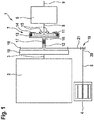
- the FIG. 1 shows a schematic representation of a drive device 1, which can be used for example for driving a motor vehicle.
- the drive device 1 has a first drive unit 2 with a first drive shaft 3 and a second drive unit 4 with a second drive shaft 5.
- the first drive unit 2 is designed as an internal combustion engine and the second drive unit 4 as an electric machine.
- the second drive unit 4 is arranged axially parallel to the first drive unit 2, in particular next to this. This is to be understood that the drive units 2 and 4 in the axial direction with respect to their drive shafts 3 and 5 in at least partial overlap, in particular in complete coverage, together. Alternatively, a coaxial arrangement of the drive units 2 and 4 may be provided.
- the drive device 1 further has a multi-speed transmission 6 and a clutch 7.
- the multi-speed transmission 6 has an input shaft 8 and an output shaft 9.
- the ratio between the input shaft 8 and the output shaft 9 is adjustable by means of multi-speed transmission 6 to different ratios.
- the drive shaft 3 is connected on its side facing away from the first drive unit 2 side with a vibration damper 10 on its input side.
- the vibration damper 10 On its side facing away from the first drive unit 2 or the first drive shaft 3 side, ie the output side, the vibration damper 10 is operatively connected to an inner support 11 of the clutch 7, in particular rigid and / or permanent.
- the inner support 11 may also be referred to as a second coupling part 11.
- the operative connection between the vibration damper 10 and the inner support 11 is provided for example via a coupling shaft 12.
- the clutch 7 is preferably designed as a multi-plate clutch, thus has from the inner support 11 and the outer support 13 outgoing slats, which intervene between each other.
- the clutch 7 can be closed so that the blades cooperate frictionally and an operative connection between the inner support 11 and the outer support 13 is made.
- the displacement of the outer support 13 is indicated by the arrows 15.
- the input shaft 8 is arranged coaxially with the coupling shaft 12 and the first drive shaft 3.
- the clutch 7 is arranged between the first drive unit 2 and the multi-speed transmission 6 in the axial direction.
- a hollow shaft 16 connected to the outer support 13 wherein the active connection is preferably rigid and / or permanent.
- the coupling shaft 12 is arranged at least partially. Especially passes through the coupling shaft 12, the hollow shaft 16 in the axial direction completely.
- the coupling shaft 12 is mounted in or on the hollow shaft 16.
- a bearing 17 is provided which rests in the radial direction on the inside on an outer circumference of the coupling shaft 12 and on the outside on an inner circumference of the hollow shaft 16 and thus supports the coupling shaft 12 in the radial direction with respect to the hollow shaft 16.
- a gear 18 is arranged or fixed, which forms part of a gear stage 19.
- the second drive unit 4 is operatively connected to the outer carrier 13 and via this with the multi-speed transmission 6 or its input shaft 8, in particular rigid and / or permanent.
- the gear stage 19 in this case has a gear 20 which is connected to the drive shaft 5, in particular arranged on this.
- the gears 18 and 20 are operatively connected to each other via an intermediate gear 21, which meshes on the one hand with the gear 20 and on the other hand with the gear 18.
- FIG. 2 shows a second embodiment of the drive device 1.
- This is basically configured similar to the first embodiment, so reference is made to the above statements and will be discussed below only the differences.
- the hollow shaft 16, the bearing 17 and the gear 18 are not provided.
- the outer support 13 has an external toothing 22, which forms part of the gear stage 19.
- the intermediate gear 21 meshes on the one hand with the gear 20 and on the other hand with the external toothing 22, so that via the gear stage 19 an operative connection between the second drive unit 4 and the outer support 13 and thus made with the multi-speed transmission 6.
- Such Design allows a further reduction of the space requirement of the drive device. 1
- Both embodiments of the drive device 1 is characterized by a compact design and therefore a small space requirement. This is made possible in particular by the axially parallel or coaxial arrangement of the first drive unit 2 and the second drive unit 4, so that both drive units 2 and 4 are readily operatively connected to the multi-speed transmission 6.
- the operative connection between the first drive unit 2 and the multi-speed transmission 6 is provided via the clutch 7. It can be optionally interrupted or produced accordingly.
- the first drive unit 2 is decoupled from the multi-speed transmission 6 in a first switching state of the clutch 7, while in a second switching state, the operative connection between the first drive unit 2 and the multi-speed transmission 6 is present.
- the second drive unit 4, however, is permanently operatively connected to the multi-speed transmission 6.
Landscapes
- Engineering & Computer Science (AREA)
- Mechanical Engineering (AREA)
- Chemical & Material Sciences (AREA)
- Combustion & Propulsion (AREA)
- Transportation (AREA)
- General Engineering & Computer Science (AREA)
- Structure Of Transmissions (AREA)
- Motor Power Transmission Devices (AREA)
- Arrangement Of Transmissions (AREA)
Abstract
Description
- Die Erfindung betrifft eine Antriebseinrichtung für ein Kraftfahrzeug, mit einem eine erste Antriebswelle aufweisenden ersten Antriebsaggregat, mit wenigstens einem eine zweite Antriebswelle aufweisenden zweiten Antriebsaggregat sowie mit einem Mehrganggetriebe, wobei das erste Antriebsaggregat über einen Schwingungsdämpfer und eine Schaltkupplung mit dem Mehrganggetriebe wirkverbunden ist.
- Die Antriebseinrichtung dient dem Antreiben des Kraftfahrzeugs, insoweit also dem Bereitstellen eines auf das Antreiben des Kraftfahrzeugs gerichteten Drehmoments. Die Antriebseinrichtung verfügt über mehrere Antriebsaggregate, insbesondere das erste Antriebsaggregat und das zweite Antriebsaggregat. Das erste Antriebsaggregat und das zweite Antriebsaggregat können unterschiedlichen Typs sein, also beispielsweise als Brennkraftmaschine und als elektrische Maschine vorliegen. In diesem Fall ist die Antriebseinrichtung als Hybridantriebseinrichtung ausgestaltet. Selbstverständlich können das erste Antriebsaggregat und das zweite Antriebsaggregat jedoch auch desselben Typs sein, also beide als Brennkraftmaschine oder als elektrische Maschine vorliegen. Beide Antriebsaggregate, also das erste Antriebsaggregat und das zweite Antriebsaggregat, weisen jeweils eine Antriebswelle auf, über welche sie das von ihnen erzeugte Drehmoment bereitstellen.
- Es ist nun Aufgabe der Erfindung, eine Antriebseinrichtung für ein Kraftfahrzeug vorzuschlagen, welche gegenüber bekannten Antriebseinrichtungen Vorteile aufweist, insbesondere kompakt und platzsparend ausgebildet ist.
- Dies wird erfindungsgemäß mit einer Antriebseinrichtung mit den Merkmalen des Anspruchs 1 erreicht. Dabei ist vorgesehen, dass die Schaltkupplung einen mit einer Eingangswelle des Mehrganggetriebes gekoppelten ersten Kupplungsteil und einen über den Schwingungsdämpfer mit dem ersten Antriebsaggregat gekoppelten zweiten Kupplungsteil aufweist, und dass das erste Antriebsaggregat und das wenigstens eine zweite Antriebsaggregat achsparallel oder koaxial zueinander angeordnet sind, wobei das wenigstens eine zweite Antriebsaggregat, insbesondere über zumindest eine Getriebestufe, mit dem ersten Kupplungsteil gekoppelt ist.
- Die Antriebseinrichtung verfügt über das Mehrganggetriebe, welches das Einstellen unterschiedlicher Übersetzungen ermöglicht. Das Mehrganggetriebe kann beispielsweise als Schaltgetriebe oder als Automatikgetriebe ausgestaltet sein. Unter dem Schaltgetriebe ist bevorzugt ein Handschaltgetriebe oder ein zumindest teilweise automatisiertes Schaltgetriebe, beispielsweise ein Doppelkupplungsgetriebe, zu verstehen. Das Automatikgetriebe bezeichnet bevorzugt ein Wandler-Automatikgetriebe. Selbstverständlich kann das Mehrganggetriebe jedoch auch als stufenloses Getriebe oder dergleichen ausgestaltet sein.
- Das Mehrganggetriebe ist bevorzugt in einer Wirkverbindung zwischen dem ersten Antriebsaggregat und/oder dem zweiten Antriebsaggregat einerseits und einer Abtriebswelle der Antriebseinrichtung andererseits angeordnet. Mithin ist mithilfe des Mehrganggetriebes die Übersetzung zwischen der ersten Antriebswelle und/oder der zweiten Antriebswelle einerseits und der Abtriebswelle der Antriebseinrichtung andererseits einstellbar.
- Das erste Antriebsaggregat ist über den Schwingungsdämpfer und die Schaltkupplung mit dem Mehrganggetriebe wirkverbunden. Der Schwingungsdämpfer kann auch als Drehschwingungsdämpfer oder als Torsionskupplung bezeichnet werden. Er dient der Dämpfung von Schwingungen beziehungsweise Drehschwingungen des ersten Antriebsaggregats, damit diese nicht oder allenfalls in gedämpfter Form auf das Mehrganggetriebe übertragen werden.
- Weiterhin verfügt die Antriebseinrichtung über die Schaltkupplung. Mittels dieser ist die Wirkverbindung zwischen dem ersten Antriebsaggregat und dem Mehrganggetriebe herstellbar beziehungsweise unterbrechbar. Das bedeutet, dass in einem ersten Schaltzustand der Schaltkupplung die Wirkverbindung zwischen dem ersten Antriebsaggregat und dem Mehrganggetriebe unterbrochen ist, während sie in einem zweiten Schaltzustand zumindest teilweise, insbesondere vollständig, hergestellt ist. In dem zweiten Schaltzustand ist das erste Antriebsaggregat beziehungsweise dessen Antriebswelle vorzugsweise mit dem Mehrganggetriebe wirkverbunden.
- Die Reihenfolge des Schwingungsdämpfers und der Schaltkupplung in der Wirkverbindung zwischen dem ersten Antriebsaggregat und dem Mehrganggetriebe ist grundsätzlich beliebig. Bevorzugt ist jedoch der Schwingungsdämpfer zwischen dem ersten Antriebsaggregat und der Schaltkupplung vorgesehen, die Schaltkupplung also über den Schwingungsdämpfer mit dem ersten Antriebsaggregat wirkverbunden.
- Die Schaltkupplung ist mehrteilig aufgebaut und verfügt über wenigstens den ersten Kupplungsteil und den zweiten Kupplungsteil. In einem ersten Schaltzustand beziehungsweise einer ersten Schaltstellung der Schaltkupplung sind der erste Kupplungsteil und der zweite Kupplungsteil voneinander entkoppelt, sodass die Schaltkupplung geöffnet ist und kein Drehmoment zwischen dem ersten Antriebsaggregat und dem Mehrganggetriebe übertragen wird. In einem zweiten Schaltzustand beziehungsweise einer zweiten Schaltstellung liegt dagegen eine Wirkverbindung zwischen dem ersten Kupplungsteil und dem zweiten Kupplungsteil vor, sodass Drehmoment zwischen dem ersten Antriebsaggregat und dem Mehrganggetriebe übertragen wird, zumindest ein Teil des Drehmoments. Bevorzugt sind in dem zweiten Schaltzustand der zweite Kupplungsteil und der erste Kupplungsteil drehfest miteinander verbunden, zumindest für ein zwischen dem ersten Antriebsaggregat und dem Mehrganggetriebe wirkenden Drehmoment, das innerhalb eines üblichen Drehmomentbereichs der Antriebseinrichtung liegt.
- Der erste Kupplungsteil der Schaltkupplung ist unmittelbar mit der Eingangswelle des Mehrganggetriebes gekoppelt, insbesondere also starr und permanent mit dieser wirkverbunden. Beispielsweise ist der erste Kupplungsteil unmittelbar auf der Eingangswelle des Mehrganggetriebes angeordnet und mit dieser verbunden. Der zweite Kupplungsteil der Schaltkupplung ist dagegen über den Schwingungsdämpfer mit dem ersten Antriebsaggregat beziehungsweise dessen Antriebswelle gekoppelt beziehungsweise wirkverbunden. Das bedeutet, dass das erste Antriebsaggregat über den Schwingungsdämpfer mit dem zweiten Kupplungsteil wirkverbunden ist. Auch diese Wirkverbindung ist bevorzugt permanent vorgesehen, jedoch aufgrund des Schwingungsdämpfers üblicherweise nicht starr.
- Die Schaltkupplung ist beispielsweise als Lamellenkupplung ausgestaltet. Hierbei verfügt sie über Lamellen, welche ausgehend von dem zweiten Kupplungsteil in radialer Richtung bezüglich einer Drehachse des zweiten Kupplungsteils nach außen ragen und dabei zwischen Lamellen eingreifen, die an dem ersten Kupplungsteil angeordnet sind und sich ausgehend von diesem in radialer Richtung nach innen erstrecken. Die Lamellen des zweiten Kupplungsteils und des ersten Kupplungsteils greifen in radialer Richtung gesehen zwischeneinander ein. In axialer Richtung gesehen liegen hierzu der zweite Kupplungsteil und der erste Kupplungsteil wenigstens teilweise in Überdeckung vor. Beispielsweise greift der zweite Kupplungsteil in den ersten Kupplungsteil ein. Der erste Kupplungsteil kann auch als Außenträger und der zweite Kupplungsteil als Innenträger bezeichnet werden.
- In dem ersten Schaltzustand der Schaltkupplung liegen die Lamellen des ersten Kupplungsteils und des zweiten Kupplungsteils voneinander beabstandet vor, insbesondere in axialer Richtung voneinander beabstandet, sodass der erste Kupplungsteil und der zweite Kupplungsteil voneinander entkoppelt sind. In dem zweiten Schaltzustand liegen die Lamellen des ersten Kupplungsteils jedoch an den Lamellen des zweiten Kupplungsteils an, sodass eine kraftschlüssige Wirkverbindung zwischen dem ersten Kupplungsteil und dem zweiten Kupplungsteil hergestellt ist. Beispielsweise ist der erste Kupplungsteil in axialer Richtung verlagerbar, um die Lamellen in dem ersten Schaltzustand voneinander zu beabstanden und in dem zweiten Schaltzustand miteinander in Wirkverbindung zu setzen.
- Selbstverständlich kann die Schaltkupplung jedoch grundsätzlich beliebig ausgestaltet sein, insbesondere als kraftschlüssige oder als formschlüssige Schaltkupplung vorliegen. Ein Beispiel für eine kraftschlüssige Schaltkupplung ist die vorstehend bereits erwähnte Lamellenkupplung. Ist die Lamellenkupplung formschlüssig, so liegt sie beispielsweise als Klauenkupplung vor. Die Schaltkupplung muss nicht notwendigerweise bedienbar beziehungsweise betätigbar sein, es kann auch ein automatisches Schalten vorgesehen sein. Die Schaltkupplung zeichnet sich jedoch dadurch aus, dass sie in den wenigstens zwei Schaltzuständen beziehungsweise Schaltstellungen vorliegen kann. Insoweit kann also die Schaltkupplung als Überholkupplung beziehungsweise Freilauf ausgestaltet sein, bei welcher/welchem der Schaltzustand von der Relativdrehzahl zwischen den Kupplungsteilen beziehungsweise den Drehrichtungen des ersten Kupplungsteils und des zweiten Kupplungsteils abhängt.
- Weiterhin ist es vorgesehen, dass das erste Antriebsaggregat und das wenigstens eine zweite Antriebsaggregat achsparallel oder koaxial zueinander angeordnet sind. Das bedeutet, dass die Antriebswelle des ersten Antriebsaggregats beziehungsweise ihre Drehachse parallel zu der Antriebswelle des zweiten Antriebsaggregats beziehungsweise ihrer Drehachse angeordnet ist. Durch eine derartige Anordnung des ersten Antriebsaggregats und des wenigstens einen zweiten Antriebsaggregats kann der Bauraum in einem Motorraum, in welchem die Antriebseinrichtung angeordnet ist, optimal ausgenutzt werden. Zudem wird die Anbindung der Antriebsaggregate an weitere Komponenten der Antriebseinrichtung, insbesondere an das Mehrganggetriebe, vereinfacht.
- Bei der achsparallelen Anordnung ist eine parallel beabstandete Anordnung der Antriebswellen beziehungsweise ihrer Drehachsen vorgesehen, während für die koaxiale Anordnung die Drehachsen der Antriebswelle des ersten Antriebsaggregats und der Antriebswelle des zweiten Antriebsaggregats zusammenfallen, also identisch sind. Bei der koaxialen Anordnung ist beispielsweise das zweite Antriebsaggregat in axialer Richtung gesehen zwischen dem Schwingungsdämpfer und dem Mehrganggetriebe angeordnet.
- Unter der achsparallelen Anordnung des ersten Antriebsaggregats und des zweiten Antriebsaggregats ist eine parallele Anordnung der jeweiligen Antriebswellen zumindest bei einer Draufsicht auf die Antriebseinrichtung zu verstehen. Demzufolge können in der allgemeinen Ausführungsform einer achsparallelen Anordnung die Antriebswellen nicht im eigentlichen Wortsinn achsparallel angeordnet sein, sondern nur in der Draufsicht parallel angeordnet zu sein scheinen. In anderen Worten sind die Antriebswellen der Antriebsaggregate windschief zueinander angeordnet, liegen jedoch in zueinander parallel angeordneten gedachten Ebenen.
- Eine Drehachse der Antriebswelle des ersten Antriebsaggregats ist also in einer ersten Ebene angeordnet und eine Drehachse der Antriebswelle des zweiten Antriebsaggregats in einer zweiten Ebene, wobei die erste Ebene und die zweite Ebene parallel zueinander liegen. Die Drehachsen sind jedoch derart ausgerichtet, dass sie windschief zueinander liegen.
- In einer bevorzugten Ausführungsform sind die Antriebswellen der Antriebsaggregate beziehungsweise ihre Drehachsen jedoch dreidimensional achsparallel, also achsparallel im Wortsinn, zueinander angeordnet. Dies ist im Rahmen dieser Beschreibung grundsätzlich der Fall, falls nicht anders festgehalten. Beispielsweise sind die Antriebswellen zusätzlich parallel zu einer Längsachse des Kraftfahrzeugs angeordnet.
- Es kann vorgesehen sein, dass das erste Antriebsaggregat und das zweite Antriebsaggregat nebeneinander angeordnet sind. Das bedeutet mit Hinblick auf ihre Antriebswellen beziehungsweise deren Drehachsen, dass die Antriebsaggregate in axialer Richtung in Überdeckung vorliegen. Das erste Antriebsaggregat und das zweite Antriebsaggregat sollen also gerade nicht in axialer Richtung voneinander beabstandet, sondern vielmehr an wenigstens einer Axialposition nebeneinander angeordnet sein. Besonders bevorzugt liegt das in axialer Richtung kleinere der Antriebsaggregate, also entweder das erste Antriebsaggregat oder das zweite Antriebsaggregat, vollständig in Überdeckung mit dem in axialer Richtung größeren der Antriebsaggregate vor. Beispielsweise ist das zweite Antriebsaggregat in axialer Richtung kleiner als das erste Antriebsaggregat.
- Die beschriebene Anordnung des ersten Antriebsaggregats und des zweiten Antriebsaggregats liegt bevorzugt in deren Einbaulage vor. Darunter ist eine endgültige Anordnung des ersten Antriebsaggregats und des zweiten Antriebsaggregats nach einer Montage der Antriebseinrichtung beziehungsweise des Kraftfahrzeugs zu verstehen. Die Einbaulage liegt also auch während eines Fahrbetriebs des Kraftfahrzeugs vor, während welchem mittels des ersten Antriebsaggregats und/oder mittels des zweiten Antriebsaggregats Antriebsleistung für ein Antreiben des Kraftfahrzeugs erzeugt und/oder bereitgestellt wird.
- Das wenigstens eine zweite Antriebsaggregat ist mit dem ersten Kupplungsteil gekoppelt. Bevorzugt liegt hierbei eine starre und/oder permanente Verbindung zwischen dem zweiten Antriebsaggregat und dem ersten Kupplungsteil vorgesehen sein. Beispielsweise greift das zweite Antriebsaggregat unmittelbar an dem ersten Kupplungsteil an, insbesondere wird der erste Kupplungsteil von der Antriebswelle des zweiten Antriebsaggregats gebildet oder umgekehrt. Bevorzugt wird eine solche Variante bei der koaxialen Anordnung der Antriebsaggregate herangezogen. Die Kopplung zwischen dem zweiten Antriebsaggregat und dem ersten Kupplungsteil kann jedoch auch über die wenigstens eine Getriebestufe realisiert sein, insbesondere wenn die Antriebsaggregate achsparallel zueinander angeordnet sind.
- Die Anbindung des zweiten Antriebsaggregats an das Mehrganggetriebe kann über die Getriebestufe vorgesehen sein. Genauer gesagt dient diese dem Koppeln des zweiten Antriebsaggregats mit dem ersten Kupplungsteil der Schaltkupplung. Insbesondere über die Getriebestufe ist eine bevorzugt starre und/oder permanente Wirkverbindung zwischen dem zweiten Antriebsaggregat und dem ersten Kupplungsteil hergestellt. Das bedeutet, dass das zweite Antriebsaggregat permanent mit dem Mehrganggetriebe wirkverbunden ist, wobei diese Wirkverbindung über den ersten Kupplungsteil der Schaltkupplung und optional über die Getriebestufe vorliegt.
- Eine bevorzugte Ausgestaltung der Erfindung sieht vor, dass die Getriebestufe als Zahnradstufe ausgebildet ist. Selbstverständlich kann das Getriebe beziehungsweise die Getriebestufe beliebig ausgestaltet sein, also beispielsweise als Radgetriebe oder als Riemengetriebe vorliegen. Besonders bevorzugt ist jedoch eine formschlüssige Wirkverbindung, welche durch die Ausgestaltung der Getriebestufe als Zahnradstufe realisiert ist. Die Zahnradstufe weist mehrere Zahnräder auf, von welchen jeweils zwei miteinander kämmen, also in Eingriff miteinander stehen.
- Bevorzugt ist es vorgesehen, dass das erste Antriebsaggregat und das zweite Antriebsaggregat bei einer bestimmten Drehrichtung der Eingangswelle dieselbe Drehrichtung aufweisen. Hierzu ist kann die Getriebestufe entsprechend ausgestaltet sein. Die Getriebestufe ist insoweit drehrichtungserhaltend ausgestaltet und verfügt zu diesem Zweck beispielsweise über eine ungerade Anzahl an Zahnrädern, also mindestens drei Zahnräder.
- Im Rahmen einer weiteren Ausgestaltung der Erfindung ist vorgesehen, dass die Schaltkupplung in einem Getriebegehäuse des Mehrganggetriebes angeordnet ist. Auf diese Art und Weise wird ein besonders hoher Integrationsgrad und insoweit ein geringer Bauraumbedarf der Antriebseinrichtung erzielt. Das Getriebegehäuse dient insbesondere der Aufnahme von Getriebeelementen des Mehrganggetriebes, also beispielsweise wenigstens eines Zahnradsatzes beziehungsweise eines Planetenradsatzes. Die Schaltkupplung ist nun ebenfalls in diesem Getriebegehäuse angeordnet, sodass die Schaltkupplung in das Mehrganggetriebe integriert ist.
- Im Rahmen einer besonders bevorzugten weiteren Ausgestaltung der Erfindung ist vorgesehen, dass an dem ersten Kupplungsteil eine Außenverzahnung ausgebildet ist, die einen Teil der Getriebestufe bildet. Wenigstens ein Rad beziehungsweise Zahnrad der Getriebestufe greift also unmittelbar an dem ersten Kupplungsteil an und kämmt dabei mit der Außenverzahnung des ersten Kupplungsteils. Vorzugsweise ist die Außenverzahnung einstückig und/oder materialeinheitlich mit dem ersten Kupplungsteil ausgebildet. Es kann jedoch auch vorgesehen sein, dass die Außenverzahnung separat von dem ersten Kupplungsteil hergestellt und nachfolgend an dem ersten Kupplungsteil befestigt wird. In jedem Fall ist jedoch die Außenverzahnung drehfest mit dem ersten Kupplungsteil verbunden.
- Eine Weiterbildung der Erfindung sieht vor, dass der erste Kupplungsteil über eine Hohlwelle mit dem zweiten Antriebsaggregat gekoppelt ist, der eine den Schwingungsdämpfer mit dem zweiten Kupplungsteil verbindende Koppelwelle angeordnet ist. Über die Hohlwelle liegt die Wirkverbindung zwischen dem ersten Kupplungsteil und dem zweiten Antriebsaggregat vor. Beispielsweise erstreckt sich die Hohlwelle ausgehend von dem ersten Kupplungsteil in axialer Richtung in Richtung des ersten Antriebsaggregats und/oder des zweiten Antriebsaggregats.
- Zusätzlich oder alternativ erstreckt sich die Hohlwelle ausgehend von dem ersten Kupplungsteil in die von dem Mehrganggetriebe abgewandte Richtung. Die Hohlwelle dient der Aufnahme wenigstens eines Teils der Koppelwelle. Über die Koppelwelle ist der Schwingungsdämpfer mit dem zweiten Kupplungsteil wirkverbunden, insbesondere starr und/oder permanent. Besonders bevorzugt durchgreift die Koppelwelle die Hohlwelle in axialer Richtung vollständig.
- Eine weitere Ausgestaltung der Erfindung sieht vor, dass die Eingangswelle einerseits und die erste Antriebswelle und/oder die Hohlwelle und/oder die Koppelwelle andererseits koaxial angeordnet sind. Eine Welle oder mehrere Wellen, die aus der ersten Antriebswelle, der Hohlwelle und der Koppelwelle ausgewählt ist/sind, sollen also koaxial zu der Eingangswelle vorliegen. Auch dies ermöglicht eine kompakte und platzsparende Ausgestaltung der Antriebseinrichtung.
- Eine bevorzugte Ausgestaltung der Erfindung sieht vor, dass die Koppelwelle über wenigstens ein Lager an der Hohlwelle gelagert ist. Das Lager liegt insoweit zwischen der Koppelwelle und der Hohlwelle vor. Besonders bevorzugt ist die Koppelwelle mittels des Lagers in der Hohlwelle gelagert. Dies bedeutet, dass das Lager in radialer Richtung gesehen innen an der Koppelwelle beziehungsweise an einem Außenumfang der Koppelwelle und in radialer Richtung außen an der Hohlwelle beziehungsweise einem Innenumfang der Hohlwelle anliegt. Besonders bevorzugt sind mehrere derartige Lager vorgesehen, die in axialer Richtung voneinander beabstandet angeordnet sind.
- Im Rahmen einer weiteren Ausführungsform der Erfindung kann vorgesehen sein, dass an der Hohlwelle ein Zahnrad angeordnet oder ausgebildet ist, das einen Teil der Getriebestufe bildet. Das Zahnrad kann Bestandteil der Hohlwelle sein und insoweit einstückig und/oder materialeinheitlich mit dieser vorliegen. Alternativ ist das Zahnrad separat von der Hohlwelle ausgebildet und an der Hohlwelle befestigt. Das Zahnrad bildet einen Teil der Getriebestufe, sodass also das zweite Antriebsaggregat über die Hohlwelle mit dem ersten Kupplungsteil und über diesen wiederum mit dem Mehrganggetriebe wirkverbunden ist, insbesondere starr und/oder permanent.
- Eine weitere bevorzugte Ausführungsform der Erfindung sieht vor, dass das Zahnrad außerhalb des Getriebegehäuses angeordnet ist. Vorstehend wurde bereits erläutert, dass die Schaltkupplung bevorzugt in dem Getriebegehäuse vorliegt. Entsprechend kann es vorgesehen sein, dass sich die Hohlwelle aus dem Getriebegehäuse heraus erstreckt, sodass das Zahnrad außerhalb des Getriebegehäuses vorliegt. Auf diese Art und Weise wird eine zuverlässige Kapselung des Mehrganggetriebes realisiert.
- Im Rahmen einer weiteren Ausgestaltung der Erfindung ist vorgesehen, dass der erste Kupplungsteil zur Aktuierung der Schaltkupplung axial verlagerbar ist. Dies ist insbesondere der Fall, falls die Schaltkupplung als Lamellenkupplung vorliegt. In dem ersten Schaltzustand der Schaltkupplung ist der ersten Kupplungsteil insoweit in einer ersten Axialposition und in einer zweiten Schaltung in einer zweiten Axialposition angeordnet. Falls die Hohlwelle vorgesehen ist, kann diese zusammen mit dem ersten Kupplungsteil in axialer Richtung verlagert werden beziehungsweise verlagerbar angeordnet sein. Hierzu ist bevorzugt die Getriebestufe derart ausgebildet, dass ein aufgrund des Verlagerns auftretender Versatz der Hohlwelle in axialer Richtung ausgeglichen wird. Insbesondere weisen die Zahnräder der Getriebestufe eine Breite auf, die gewährleistet, dass sie in jeder Stellung des ersten Kupplungsteils miteinander in Eingriff stehen.
- Schließlich kann in einer weiteren Ausführungsform der Erfindung vorgesehen sein, dass das erste Antriebsaggregat als Brennkraftmaschine und/oder das zweite Antriebsaggregat als elektrische Maschine vorliegt. Auf eine derartige Ausgestaltung der insoweit als Hybridantriebseinrichtung ausgestalteten Antriebseinrichtung wurde vorstehend bereits hingewiesen. Die Erfindung wird nachfolgend anhand der in der Zeichnung dargestellten Ausführungsbeispiele näher erläutert, ohne dass eine Beschränkung der Erfindung erfolgt. Dabei zeigt:
- Figur 1
- eine schematische Darstellung einer Antriebseinrichtung in einer ersten Ausführungsform, und
- Figur 2
- die Antriebseinrichtung in einer zweiten Ausführungsform.
- Die
Figur 1 zeigt eine schematische Darstellung einer Antriebseinrichtung 1, die beispielswiese zum Antreiben eines Kraftfahrzeugs verwendet werden kann. Die Antriebseinrichtung 1 verfügt über ein erstes Antriebsaggregat 2 mit einer ersten Antriebswelle 3 und über ein zweites Antriebsaggregat 4 mit einer zweiten Antriebswelle 5. Das erste Antriebsaggregat 2 ist als Brennkraftmaschine und das zweite Antriebsaggregat 4 als elektrische Maschine ausgestaltet. Das zweite Antriebsaggregat 4 ist achsparallel zu dem ersten Antriebsaggregat 2 angeordnet, insbesondere neben diesem. Darunter ist zu verstehen, dass die Antriebsaggregate 2 und 4 in axialer Richtung bezüglich ihrer Antriebswellen 3 und 5 in zumindest teilweiser Überdeckung, insbesondere in vollständiger Überdeckung, miteinander vorliegen. Alternativ kann eine koaxiale Anordnung der Antriebsaggregate 2 und 4 vorgesehen sein. - Die Antriebseinrichtung 1 verfügt weiterhin über ein Mehrganggetriebe 6 sowie eine Schaltkupplung 7. Das Mehrganggetriebe 6 verfügt über eine Eingangswelle 8 und eine Ausgangswelle 9. Die Übersetzung zwischen der Eingangswelle 8 und der Ausgangswelle 9 ist mithilfe des Mehrganggetriebes 6 auf unterschiedliche Übersetzungen einstellbar.
- Die Antriebswelle 3 ist auf ihrer dem ersten Antriebsaggregat 2 abgewandten Seite mit einem Schwingungsdämpfer 10 auf dessen Eingangsseite verbunden. Auf seiner dem ersten Antriebsaggregat 2 beziehungsweise der ersten Antriebswelle 3 abgewandten Seite, also ausgangsseitig, ist der Schwingungsdämpfer 10 mit einem Innenträger 11 der Schaltkupplung 7 wirkverbunden, insbesondere starr und/oder permanent. Der Innenträger 11 kann auch als zweiter Kupplungsteil 11 bezeichnet werden. Die Wirkverbindung zwischen dem Schwingungsdämpfer 10 und dem Innenträger 11 ist beispielsweise über eine Koppelwelle 12 vorgesehen.
- Ein Außenträger 13 der Schaltkupplung 7, der auch als erster Kupplungsteil 13 bezeichnet werden kann, ist mit dem Mehrganggetriebe 6 beziehungsweise dessen Eingangswelle 8 wirkverbunden, insbesondere starr und/oder permanent. Die Schaltkupplung 7 ist bevorzugt als Lamellenkupplung ausgestaltet, weist also von dem Innenträger 11 und dem Außenträger 13 ausgehende Lamellen auf, welche zwischeneinander eingreifen. Beispielsweise durch eine axiale Verlagerung des Außenträgers 13 mittels eines Aktuators 14 kann die Schaltkupplung 7 geschlossen werden, sodass die Lamellen kraftschlüssig zusammenwirken und eine Wirkverbindung zwischen dem Innenträger 11 und dem Außenträger 13 hergestellt ist. Die Verlagerung des Außenträgers 13 ist durch die Pfeile 15 angedeutet. Es ist deutlich zu erkennen, dass die Eingangswelle 8 koaxial zu der Koppelwelle 12 und der ersten Antriebswelle 3 angeordnet ist. Insbesondere ist in axialer Richtung die Schaltkupplung 7 zwischen dem ersten Antriebsaggregat 2 und dem Mehrganggetriebe 6 angeordnet.
- In der hier dargestellten ersten Ausführungsform ist eine mit dem Außenträger 13 verbundene Hohlwelle 16 vorgesehen, wobei die Wirkverbindung bevorzugt starr und/oder permanent ist. In der Hohlwelle 16 ist wenigstens bereichsweise die Koppelwelle 12 angeordnet. Insbesondere durchgreift die Koppelwelle 12 die Hohlwelle 16 in axialer Richtung vollständig. Zudem kann es vorgesehen sein, dass die Koppelwelle 12 in beziehungsweise an der Hohlwelle 16 gelagert ist. Zu diesem Zweck ist ein Lager 17 vorgesehen, das in radialer Richtung innen an einem Außenumfang der Koppelwelle 12 und außen an einem Innenumfang der Hohlwelle 16 anliegt und mithin die Koppelwelle 12 in radialer Richtung bezüglich der Hohlwelle 16 lagert.
- An der Hohlwelle 16 ist ein Zahnrad 18 angeordnet beziehungsweise befestigt, das einen Teil einer Getriebestufe 19 bildet. Über die Getriebestufe 19 ist das zweite Antriebsaggregat 4 mit dem Außenträger 13 und über diesen mit dem Mehrganggetriebe 6 beziehungsweise dessen Eingangswelle 8 wirkverbunden, insbesondere starr und/oder permanent. Die Getriebestufe 19 weist dabei ein Zahnrad 20 auf, das mit der Antriebswelle 5 verbunden ist, insbesondere auf dieser angeordnet ist. Die Zahnräder 18 und 20 sind über ein Zwischenrad 21 miteinander wirkverbunden, das einerseits mit dem Zahnrad 20 und andererseits mit dem Zahnrad 18 kämmt.
- Die
Figur 2 zeigt eine zweite Ausführungsform der Antriebseinrichtung 1. Diese ist grundsätzlich ähnlich zu der ersten Ausführungsform ausgestaltet, sodass auf die vorstehenden Ausführungen verwiesen und nachfolgend lediglich auf die Unterschiede eingegangen wird. Diese liegen darin, dass die Hohlwelle 16, das Lager 17 und das Zahnrad 18 nicht vorgesehen sind. Vielmehr verfügt der Außenträger 13 über eine Außenverzahnung 22, die einen Teil der Getriebestufe 19 bildet. Zu diesem Zweck kämmt das Zwischenrad 21 einerseits mit dem Zahnrad 20 und andererseits mit der Außenverzahnung 22, sodass über die Getriebestufe 19 eine Wirkverbindung zwischen dem zweiten Antriebsaggregat 4 und dem Außenträger 13 und mithin mit dem Mehrganggetriebe 6 hergestellt ist. Eine derartige Ausgestaltung ermöglicht eine weitere Reduktion des Bauraumbedarfs der Antriebseinrichtung 1. - Beide Ausführungsformen der Antriebseinrichtung 1 zeichnet sich durch eine kompakte Bauform und mithin einen geringen Bauraumbedarf aus. Dies wird insbesondere ermöglicht durch die achsparallele oder koaxiale Anordnung des ersten Antriebsaggregats 2 und des zweiten Antriebsaggregats 4, sodass beide Antriebsaggregate 2 und 4 ohne weiteres mit dem Mehrganggetriebe 6 wirkverbindbar sind. Die Wirkverbindung zwischen dem ersten Antriebsaggregat 2 und dem Mehrganggetriebe 6 ist über die Schaltkupplung 7 vorgesehen. Sie kann entsprechend wahlweise unterbrochen oder hergestellt werden. Insbesondere ist das erste Antriebsaggregat 2 in einem ersten Schaltzustand der Schaltkupplung 7 von dem Mehrganggetriebe 6 entkoppelt, während in einem zweiten Schaltzustand die Wirkverbindung zwischen dem ersten Antriebsaggregat 2 und dem Mehrganggetriebe 6 vorliegt. Das zweite Antriebsaggregat 4 ist dagegen permanent mit dem Mehrganggetriebe 6 wirkverbunden.
Claims (10)
- Antriebseinrichtung (1) für ein Kraftfahrzeug, mit einem eine erste Antriebswelle (3) aufweisenden ersten Antriebsaggregat (2), mit wenigstens einem eine zweite Antriebswelle (5) aufweisenden zweiten Antriebsaggregat (4) sowie mit einem Mehrganggetriebe (6), wobei das erste Antriebsaggregat (2) über einen Schwingungsdämpfer (10) und eine Schaltkupplung (7) mit dem Mehrganggetriebe (6) wirkverbunden ist, dadurch gekennzeichnet, dass die Schaltkupplung (7) einen mit einer Eingangswelle (8) des Mehrganggetriebes (6) gekoppelten ersten Kupplungsteil (13) und einen über den Schwingungsdämpfer (10) mit dem ersten Antriebsaggregat (2) gekoppelten zweiten Kupplungsteil (11) aufweist, und dass das erste Antriebsaggregat (2) und das wenigstens eine zweite Antriebsaggregat (4) achsparallel oder koaxial zueinander angeordnet sind, wobei das wenigstens eine zweite Antriebsaggregat (4), insbesondere über zumindest eine Getriebestufe (19), mit dem ersten Kupplungsteil (13) gekoppelt ist.
- Antriebseinrichtung nach Anspruch 1, dadurch gekennzeichnet, dass die Schaltkupplung (7) in einem Getriebegehäuse des Mehrganggetriebes (6) angeordnet ist.
- Antriebseinrichtung nach einem der vorhergehenden Ansprüche, dadurch gekennzeichnet, dass an dem ersten Kupplungsteil (13) eine Außenverzahnung (22) ausgebildet ist, die einen Teil der Getriebestufe (19) bildet.
- Antriebseinrichtung nach einem der vorhergehenden Ansprüche, dadurch gekennzeichnet, dass der erste Kupplungsteil (13) über eine Hohlwelle (16) mit dem zweiten Antriebsaggregat (4) gekoppelt ist, in der eine den Schwingungsdämpfer (10) mit dem zweiten Kupplungsteil (11) verbindende Koppelwelle (12) angeordnet ist.
- Antriebseinrichtung nach einem der vorhergehenden Ansprüche, dadurch gekennzeichnet, dass die Eingangswelle (8) einerseits und die erste Antriebswelle (3) und/oder die Hohlwelle (16) und/oder die Koppelwelle (12) andererseits koaxial angeordnet sind.
- Antriebseinrichtung nach einem der vorhergehenden Ansprüche, dadurch gekennzeichnet, dass die Koppelwelle (12) über wenigstens ein Lager (17) an der Hohlwelle (16) gelagert ist.
- Antriebseinrichtung nach einem der vorhergehenden Ansprüche, dadurch gekennzeichnet, dass an der Hohlwelle (16) ein Zahnrad (18) angeordnet oder ausgebildet ist, das einen Teil der Getriebestufe (19) bildet.
- Antriebseinrichtung nach einem der vorhergehenden Ansprüche, dadurch gekennzeichnet, dass das Zahnrad (18) außerhalb des Getriebegehäuses angeordnet ist.
- Antriebseinrichtung nach einem der vorhergehenden Ansprüche, dadurch gekennzeichnet, dass der erste Kupplungsteil (13) zur Aktuierung der Schaltkupplung (7) axial verlagerbar ist.
- Antriebseinrichtung nach einem der vorhergehenden Ansprüche, dadurch gekennzeichnet, dass das erste Antriebsaggregat (2) als Brennkraftmaschine und/oder das zweite Antriebsaggregat (4) als elektrische Maschine vorliegt.
Applications Claiming Priority (1)
| Application Number | Priority Date | Filing Date | Title |
|---|---|---|---|
| DE102016001199.8A DE102016001199B4 (de) | 2016-02-03 | 2016-02-03 | Antriebseinrichtung für ein Kraftfahrzeug |
Publications (2)
| Publication Number | Publication Date |
|---|---|
| EP3202607A1 true EP3202607A1 (de) | 2017-08-09 |
| EP3202607B1 EP3202607B1 (de) | 2024-02-21 |
Family
ID=57629373
Family Applications (1)
| Application Number | Title | Priority Date | Filing Date |
|---|---|---|---|
| EP16206051.1A Active EP3202607B1 (de) | 2016-02-03 | 2016-12-22 | Antriebseinrichtung für ein kraftfahrzeug |
Country Status (4)
| Country | Link |
|---|---|
| US (1) | US10384526B2 (de) |
| EP (1) | EP3202607B1 (de) |
| CN (1) | CN107031376B (de) |
| DE (1) | DE102016001199B4 (de) |
Cited By (2)
| Publication number | Priority date | Publication date | Assignee | Title |
|---|---|---|---|---|
| FR3107233A1 (fr) * | 2020-02-18 | 2021-08-20 | Valeo Embrayages | Chaine de traction de vehicule hybride |
| EP3516250B1 (de) | 2016-09-20 | 2023-12-20 | Schaeffler Technologies AG & Co. KG | Mehrfachkupplungseinrichtung und hybridmodul für ein kraftfahrzeug |
Families Citing this family (1)
| Publication number | Priority date | Publication date | Assignee | Title |
|---|---|---|---|---|
| DE102019209986A1 (de) * | 2019-07-08 | 2021-01-14 | Zf Friedrichshafen Ag | Antriebsstrang für eine Arbeitsmaschine und Arbeitsmaschine |
Citations (6)
| Publication number | Priority date | Publication date | Assignee | Title |
|---|---|---|---|---|
| DE19941705A1 (de) * | 1998-09-09 | 2000-03-16 | Luk Lamellen & Kupplungsbau | Antriebsstrang |
| US20090105040A1 (en) * | 2007-10-19 | 2009-04-23 | Aisin Aw Co., Ltd. | Hybrid drive device |
| DE102008040494A1 (de) * | 2008-07-17 | 2010-01-21 | Zf Friedrichshafen Ag | Hybridgetriebe eines Hybridantriebsstrangs eines Kraftfahrzeugs |
| DE102009013945A1 (de) * | 2009-03-19 | 2010-09-23 | Dr.Ing.H.C.F.Porsche Aktiengesellschaft | Antriebsstrang für ein Hybridfahrzeug |
| US20120242199A1 (en) * | 2009-12-18 | 2012-09-27 | Toyota Jidosha Kabushiki Kaisha | Vehicle driving apparatus |
| EP2886383A2 (de) * | 2013-12-19 | 2015-06-24 | GETRAG Getriebe- und Zahnradfabrik Hermann Hagenmeyer GmbH & Cie KG | Hybrid-Antriebsstrang für ein Kraftfahrzeug |
Family Cites Families (17)
| Publication number | Priority date | Publication date | Assignee | Title |
|---|---|---|---|---|
| US6965196B2 (en) * | 1997-08-04 | 2005-11-15 | Lumimove, Inc. | Electroluminescent sign |
| US6254507B1 (en) * | 2000-01-18 | 2001-07-03 | General Motors Corporation | Reverse one-way torque converter clutch |
| JP4523419B2 (ja) | 2002-08-27 | 2010-08-11 | ルーク ラメレン ウント クツプルングスバウ ベタイリグングス コマンディートゲゼルシャフト | 自動車のための伝動装置配置構造 |
| FR2871111B1 (fr) | 2004-06-03 | 2006-09-22 | Peugeot Citroen Automobiles Sa | Element de transmission pour une chaine de traction de type hybride parallele |
| US7753149B2 (en) * | 2004-11-22 | 2010-07-13 | Toyota Jidosha Kabushiki Kaisha | Vehicle driving apparatus |
| EP1906224B1 (de) * | 2005-07-21 | 2012-01-25 | Nikon Corporation | Konfokale Mikroskopvorrichtung |
| DE102006034945A1 (de) * | 2006-07-28 | 2008-04-10 | Zf Friedrichshafen Ag | Antriebsanordnung für ein Hybridfahrzeug |
| DE102008040498A1 (de) * | 2008-07-17 | 2010-01-21 | Zf Friedrichshafen Ag | Hybridantriebsstrang eines Kraftfahrzeugs |
| US8835576B2 (en) * | 2010-07-09 | 2014-09-16 | Univation Technologies, Llc | Ethylene expansion for low temperature refrigeration in polyethylene vent recovery |
| JP2012086826A (ja) * | 2010-09-24 | 2012-05-10 | Aisin Aw Co Ltd | 車両用駆動装置 |
| DE102011005532A1 (de) * | 2011-03-15 | 2012-09-20 | Zf Friedrichshafen Ag | Hybridantrieb eines Kraftfahrzeugs |
| AT511632B1 (de) * | 2011-06-30 | 2013-04-15 | Avl List Gmbh | Antriebsstrang für ein fahrzeug |
| DE102011085201A1 (de) * | 2011-10-26 | 2013-05-02 | Zf Friedrichshafen Ag | Vorrichtung für einen Antriebsstrang eines Hybridfahrzeugs, Antriebsstrang und Verfahren zum Betreiben derselben |
| JP5853761B2 (ja) * | 2012-02-24 | 2016-02-09 | 日産自動車株式会社 | 駆動力伝達装置 |
| DE102012220828A1 (de) * | 2012-11-15 | 2014-05-15 | Zf Friedrichshafen Ag | Verfahren zum Betreiben einer Antriebseinheit für ein Hybridfahrzeug |
| US9108505B2 (en) * | 2013-05-28 | 2015-08-18 | Ford Global Technologies, Llc | Powersplit powertrain for a hybrid electric vehicle |
| KR101509732B1 (ko) | 2013-10-28 | 2015-04-08 | 현대자동차 주식회사 | 하이브리드 차량용 변속장치 |
-
2016
- 2016-02-03 DE DE102016001199.8A patent/DE102016001199B4/de not_active Expired - Fee Related
- 2016-12-22 EP EP16206051.1A patent/EP3202607B1/de active Active
-
2017
- 2017-01-25 CN CN201710060963.4A patent/CN107031376B/zh not_active Expired - Fee Related
- 2017-01-31 US US15/420,851 patent/US10384526B2/en active Active
Patent Citations (6)
| Publication number | Priority date | Publication date | Assignee | Title |
|---|---|---|---|---|
| DE19941705A1 (de) * | 1998-09-09 | 2000-03-16 | Luk Lamellen & Kupplungsbau | Antriebsstrang |
| US20090105040A1 (en) * | 2007-10-19 | 2009-04-23 | Aisin Aw Co., Ltd. | Hybrid drive device |
| DE102008040494A1 (de) * | 2008-07-17 | 2010-01-21 | Zf Friedrichshafen Ag | Hybridgetriebe eines Hybridantriebsstrangs eines Kraftfahrzeugs |
| DE102009013945A1 (de) * | 2009-03-19 | 2010-09-23 | Dr.Ing.H.C.F.Porsche Aktiengesellschaft | Antriebsstrang für ein Hybridfahrzeug |
| US20120242199A1 (en) * | 2009-12-18 | 2012-09-27 | Toyota Jidosha Kabushiki Kaisha | Vehicle driving apparatus |
| EP2886383A2 (de) * | 2013-12-19 | 2015-06-24 | GETRAG Getriebe- und Zahnradfabrik Hermann Hagenmeyer GmbH & Cie KG | Hybrid-Antriebsstrang für ein Kraftfahrzeug |
Cited By (3)
| Publication number | Priority date | Publication date | Assignee | Title |
|---|---|---|---|---|
| EP3516250B1 (de) | 2016-09-20 | 2023-12-20 | Schaeffler Technologies AG & Co. KG | Mehrfachkupplungseinrichtung und hybridmodul für ein kraftfahrzeug |
| FR3107233A1 (fr) * | 2020-02-18 | 2021-08-20 | Valeo Embrayages | Chaine de traction de vehicule hybride |
| WO2021165382A1 (fr) * | 2020-02-18 | 2021-08-26 | Valeo Embrayages | Chaine de traction de vehicule hybride |
Also Published As
| Publication number | Publication date |
|---|---|
| CN107031376B (zh) | 2019-07-09 |
| CN107031376A (zh) | 2017-08-11 |
| US20170217300A1 (en) | 2017-08-03 |
| DE102016001199A1 (de) | 2017-08-03 |
| DE102016001199B4 (de) | 2022-10-13 |
| EP3202607B1 (de) | 2024-02-21 |
| US10384526B2 (en) | 2019-08-20 |
Similar Documents
| Publication | Publication Date | Title |
|---|---|---|
| EP1633994B1 (de) | Planetengetriebe | |
| DE112009000016B4 (de) | Getriebe, insbesondere Doppelkupplungsgetriebe | |
| EP3049694B1 (de) | Drehschwingungsdämpferanordnung in einem antriebsstrang eines fahrzeugs | |
| EP1996834B1 (de) | Zweistufiges werkzeugmaschinengetriebeanordnung, insbesondere spindelgetriebe | |
| EP1627164A1 (de) | Planetengetriebe | |
| EP3118484B1 (de) | Getriebe für ein hydridfahrzeug, antriebsstrang für ein hybridfahrzeug mit einem solchen getriebe, sowie verfahren zum anfahren eines hybridfahrzeuges | |
| DE102013018996A1 (de) | Torsionsschwingungsdämpfer für den Antriebsstrang eines Kraftfahrzeugs und Antriebsstrang mit einem solchen Torsionsschwingungsdämpfer | |
| DE102016001199B4 (de) | Antriebseinrichtung für ein Kraftfahrzeug | |
| WO2022057973A1 (de) | Mehr-gang-getriebe mit einem zwei verzahnungsbereiche aufweisenden differential; sowie antriebseinheit | |
| EP3882478A1 (de) | Antriebsstrang mit einer beweglichen kupplung zwischen einer motorwelle und einer eingangswelle eines schaltgetriebes | |
| EP3171054A1 (de) | Getriebe für ein kraftfahrzeug, sowie antriebsstrang für ein kraftfahrzeug | |
| EP3892889A1 (de) | Spannungswellengetriebe | |
| DE102019205755B4 (de) | Getriebeanordnung und Kraftfahrzeug | |
| DE3809191A1 (de) | Anlassermotor | |
| DE102020006369B4 (de) | Hybrid-Antriebsvorrichtung | |
| DE102015225583A1 (de) | Getriebe, insbesondere für den Achsantrieb eines Fahrrades oder eines Kraftfahrzeuges, insbesondere eines Elektrofahrrades oder eines Hybrid-Kraftfahrzeuges | |
| DE102006033983A1 (de) | Getriebe mit mindestens zwei Planetenradstufen | |
| DE102020109755A1 (de) | Spannungswellengetriebe | |
| EP3147539B1 (de) | Getriebe für ein kraftfahrzeug | |
| EP3198170B1 (de) | Schaltgetriebe für ein kraftfahrzeug | |
| DE102019205754B4 (de) | Schaltanordnung und Planetengetriebe sowie Kraftfahrzeug | |
| WO2018197125A1 (de) | Getriebe für ein kraftfahrzeug | |
| WO2009083054A1 (de) | Getriebe | |
| WO2018197126A1 (de) | Getriebe für ein kraftfahrzeug | |
| DE102016225733A1 (de) | Mehrstufengetriebe |
Legal Events
| Date | Code | Title | Description |
|---|---|---|---|
| PUAI | Public reference made under article 153(3) epc to a published international application that has entered the european phase |
Free format text: ORIGINAL CODE: 0009012 |
|
| STAA | Information on the status of an ep patent application or granted ep patent |
Free format text: STATUS: THE APPLICATION HAS BEEN PUBLISHED |
|
| AK | Designated contracting states |
Kind code of ref document: A1 Designated state(s): AL AT BE BG CH CY CZ DE DK EE ES FI FR GB GR HR HU IE IS IT LI LT LU LV MC MK MT NL NO PL PT RO RS SE SI SK SM TR |
|
| AX | Request for extension of the european patent |
Extension state: BA ME |
|
| STAA | Information on the status of an ep patent application or granted ep patent |
Free format text: STATUS: REQUEST FOR EXAMINATION WAS MADE |
|
| 17P | Request for examination filed |
Effective date: 20180209 |
|
| RBV | Designated contracting states (corrected) |
Designated state(s): AL AT BE BG CH CY CZ DE DK EE ES FI FR GB GR HR HU IE IS IT LI LT LU LV MC MK MT NL NO PL PT RO RS SE SI SK SM TR |
|
| RIC1 | Information provided on ipc code assigned before grant |
Ipc: B60K 6/48 20071001AFI20170608BHEP Ipc: B60K 6/40 20071001ALI20170608BHEP |
|
| STAA | Information on the status of an ep patent application or granted ep patent |
Free format text: STATUS: EXAMINATION IS IN PROGRESS |
|
| 17Q | First examination report despatched |
Effective date: 20210225 |
|
| P01 | Opt-out of the competence of the unified patent court (upc) registered |
Effective date: 20230529 |
|
| GRAP | Despatch of communication of intention to grant a patent |
Free format text: ORIGINAL CODE: EPIDOSNIGR1 |
|
| STAA | Information on the status of an ep patent application or granted ep patent |
Free format text: STATUS: GRANT OF PATENT IS INTENDED |
|
| INTG | Intention to grant announced |
Effective date: 20231110 |
|
| GRAS | Grant fee paid |
Free format text: ORIGINAL CODE: EPIDOSNIGR3 |
|
| GRAA | (expected) grant |
Free format text: ORIGINAL CODE: 0009210 |
|
| STAA | Information on the status of an ep patent application or granted ep patent |
Free format text: STATUS: THE PATENT HAS BEEN GRANTED |
|
| AK | Designated contracting states |
Kind code of ref document: B1 Designated state(s): AL AT BE BG CH CY CZ DE DK EE ES FI FR GB GR HR HU IE IS IT LI LT LU LV MC MK MT NL NO PL PT RO RS SE SI SK SM TR |
|
| REG | Reference to a national code |
Ref country code: GB Ref legal event code: FG4D Free format text: NOT ENGLISH |
|
| REG | Reference to a national code |
Ref country code: CH Ref legal event code: EP |
|
| REG | Reference to a national code |
Ref country code: DE Ref legal event code: R096 Ref document number: 502016016382 Country of ref document: DE |
|
| REG | Reference to a national code |
Ref country code: IE Ref legal event code: FG4D Free format text: LANGUAGE OF EP DOCUMENT: GERMAN |
|
| REG | Reference to a national code |
Ref country code: LT Ref legal event code: MG9D |
|
| REG | Reference to a national code |
Ref country code: NL Ref legal event code: MP Effective date: 20240221 |
|
| PG25 | Lapsed in a contracting state [announced via postgrant information from national office to epo] |
Ref country code: IS Free format text: LAPSE BECAUSE OF FAILURE TO SUBMIT A TRANSLATION OF THE DESCRIPTION OR TO PAY THE FEE WITHIN THE PRESCRIBED TIME-LIMIT Effective date: 20240621 |
|
| PG25 | Lapsed in a contracting state [announced via postgrant information from national office to epo] |
Ref country code: LT Free format text: LAPSE BECAUSE OF FAILURE TO SUBMIT A TRANSLATION OF THE DESCRIPTION OR TO PAY THE FEE WITHIN THE PRESCRIBED TIME-LIMIT Effective date: 20240221 |
|
| PG25 | Lapsed in a contracting state [announced via postgrant information from national office to epo] |
Ref country code: GR Free format text: LAPSE BECAUSE OF FAILURE TO SUBMIT A TRANSLATION OF THE DESCRIPTION OR TO PAY THE FEE WITHIN THE PRESCRIBED TIME-LIMIT Effective date: 20240522 |
|
| PG25 | Lapsed in a contracting state [announced via postgrant information from national office to epo] |
Ref country code: NL Free format text: LAPSE BECAUSE OF FAILURE TO SUBMIT A TRANSLATION OF THE DESCRIPTION OR TO PAY THE FEE WITHIN THE PRESCRIBED TIME-LIMIT Effective date: 20240221 Ref country code: RS Free format text: LAPSE BECAUSE OF FAILURE TO SUBMIT A TRANSLATION OF THE DESCRIPTION OR TO PAY THE FEE WITHIN THE PRESCRIBED TIME-LIMIT Effective date: 20240521 Ref country code: HR Free format text: LAPSE BECAUSE OF FAILURE TO SUBMIT A TRANSLATION OF THE DESCRIPTION OR TO PAY THE FEE WITHIN THE PRESCRIBED TIME-LIMIT Effective date: 20240221 |
|
| PG25 | Lapsed in a contracting state [announced via postgrant information from national office to epo] |
Ref country code: ES Free format text: LAPSE BECAUSE OF FAILURE TO SUBMIT A TRANSLATION OF THE DESCRIPTION OR TO PAY THE FEE WITHIN THE PRESCRIBED TIME-LIMIT Effective date: 20240221 |
|
| PG25 | Lapsed in a contracting state [announced via postgrant information from national office to epo] |
Ref country code: RS Free format text: LAPSE BECAUSE OF FAILURE TO SUBMIT A TRANSLATION OF THE DESCRIPTION OR TO PAY THE FEE WITHIN THE PRESCRIBED TIME-LIMIT Effective date: 20240521 Ref country code: NO Free format text: LAPSE BECAUSE OF FAILURE TO SUBMIT A TRANSLATION OF THE DESCRIPTION OR TO PAY THE FEE WITHIN THE PRESCRIBED TIME-LIMIT Effective date: 20240521 Ref country code: NL Free format text: LAPSE BECAUSE OF FAILURE TO SUBMIT A TRANSLATION OF THE DESCRIPTION OR TO PAY THE FEE WITHIN THE PRESCRIBED TIME-LIMIT Effective date: 20240221 Ref country code: LT Free format text: LAPSE BECAUSE OF FAILURE TO SUBMIT A TRANSLATION OF THE DESCRIPTION OR TO PAY THE FEE WITHIN THE PRESCRIBED TIME-LIMIT Effective date: 20240221 Ref country code: IS Free format text: LAPSE BECAUSE OF FAILURE TO SUBMIT A TRANSLATION OF THE DESCRIPTION OR TO PAY THE FEE WITHIN THE PRESCRIBED TIME-LIMIT Effective date: 20240621 Ref country code: HR Free format text: LAPSE BECAUSE OF FAILURE TO SUBMIT A TRANSLATION OF THE DESCRIPTION OR TO PAY THE FEE WITHIN THE PRESCRIBED TIME-LIMIT Effective date: 20240221 Ref country code: GR Free format text: LAPSE BECAUSE OF FAILURE TO SUBMIT A TRANSLATION OF THE DESCRIPTION OR TO PAY THE FEE WITHIN THE PRESCRIBED TIME-LIMIT Effective date: 20240522 Ref country code: FI Free format text: LAPSE BECAUSE OF FAILURE TO SUBMIT A TRANSLATION OF THE DESCRIPTION OR TO PAY THE FEE WITHIN THE PRESCRIBED TIME-LIMIT Effective date: 20240221 Ref country code: ES Free format text: LAPSE BECAUSE OF FAILURE TO SUBMIT A TRANSLATION OF THE DESCRIPTION OR TO PAY THE FEE WITHIN THE PRESCRIBED TIME-LIMIT Effective date: 20240221 Ref country code: BG Free format text: LAPSE BECAUSE OF FAILURE TO SUBMIT A TRANSLATION OF THE DESCRIPTION OR TO PAY THE FEE WITHIN THE PRESCRIBED TIME-LIMIT Effective date: 20240221 |
|
| PG25 | Lapsed in a contracting state [announced via postgrant information from national office to epo] |
Ref country code: PT Free format text: LAPSE BECAUSE OF FAILURE TO SUBMIT A TRANSLATION OF THE DESCRIPTION OR TO PAY THE FEE WITHIN THE PRESCRIBED TIME-LIMIT Effective date: 20240621 Ref country code: PL Free format text: LAPSE BECAUSE OF FAILURE TO SUBMIT A TRANSLATION OF THE DESCRIPTION OR TO PAY THE FEE WITHIN THE PRESCRIBED TIME-LIMIT Effective date: 20240221 |
|
| PG25 | Lapsed in a contracting state [announced via postgrant information from national office to epo] |
Ref country code: SE Free format text: LAPSE BECAUSE OF FAILURE TO SUBMIT A TRANSLATION OF THE DESCRIPTION OR TO PAY THE FEE WITHIN THE PRESCRIBED TIME-LIMIT Effective date: 20240221 Ref country code: PT Free format text: LAPSE BECAUSE OF FAILURE TO SUBMIT A TRANSLATION OF THE DESCRIPTION OR TO PAY THE FEE WITHIN THE PRESCRIBED TIME-LIMIT Effective date: 20240621 Ref country code: PL Free format text: LAPSE BECAUSE OF FAILURE TO SUBMIT A TRANSLATION OF THE DESCRIPTION OR TO PAY THE FEE WITHIN THE PRESCRIBED TIME-LIMIT Effective date: 20240221 Ref country code: LV Free format text: LAPSE BECAUSE OF FAILURE TO SUBMIT A TRANSLATION OF THE DESCRIPTION OR TO PAY THE FEE WITHIN THE PRESCRIBED TIME-LIMIT Effective date: 20240221 |
|
| PG25 | Lapsed in a contracting state [announced via postgrant information from national office to epo] |
Ref country code: DK Free format text: LAPSE BECAUSE OF FAILURE TO SUBMIT A TRANSLATION OF THE DESCRIPTION OR TO PAY THE FEE WITHIN THE PRESCRIBED TIME-LIMIT Effective date: 20240221 |
|
| PG25 | Lapsed in a contracting state [announced via postgrant information from national office to epo] |
Ref country code: SM Free format text: LAPSE BECAUSE OF FAILURE TO SUBMIT A TRANSLATION OF THE DESCRIPTION OR TO PAY THE FEE WITHIN THE PRESCRIBED TIME-LIMIT Effective date: 20240221 |
|
| PG25 | Lapsed in a contracting state [announced via postgrant information from national office to epo] |
Ref country code: CZ Free format text: LAPSE BECAUSE OF FAILURE TO SUBMIT A TRANSLATION OF THE DESCRIPTION OR TO PAY THE FEE WITHIN THE PRESCRIBED TIME-LIMIT Effective date: 20240221 Ref country code: EE Free format text: LAPSE BECAUSE OF FAILURE TO SUBMIT A TRANSLATION OF THE DESCRIPTION OR TO PAY THE FEE WITHIN THE PRESCRIBED TIME-LIMIT Effective date: 20240221 |
|
| PG25 | Lapsed in a contracting state [announced via postgrant information from national office to epo] |
Ref country code: SK Free format text: LAPSE BECAUSE OF FAILURE TO SUBMIT A TRANSLATION OF THE DESCRIPTION OR TO PAY THE FEE WITHIN THE PRESCRIBED TIME-LIMIT Effective date: 20240221 |
|
| PG25 | Lapsed in a contracting state [announced via postgrant information from national office to epo] |
Ref country code: SM Free format text: LAPSE BECAUSE OF FAILURE TO SUBMIT A TRANSLATION OF THE DESCRIPTION OR TO PAY THE FEE WITHIN THE PRESCRIBED TIME-LIMIT Effective date: 20240221 Ref country code: SK Free format text: LAPSE BECAUSE OF FAILURE TO SUBMIT A TRANSLATION OF THE DESCRIPTION OR TO PAY THE FEE WITHIN THE PRESCRIBED TIME-LIMIT Effective date: 20240221 Ref country code: RO Free format text: LAPSE BECAUSE OF FAILURE TO SUBMIT A TRANSLATION OF THE DESCRIPTION OR TO PAY THE FEE WITHIN THE PRESCRIBED TIME-LIMIT Effective date: 20240221 Ref country code: EE Free format text: LAPSE BECAUSE OF FAILURE TO SUBMIT A TRANSLATION OF THE DESCRIPTION OR TO PAY THE FEE WITHIN THE PRESCRIBED TIME-LIMIT Effective date: 20240221 Ref country code: DK Free format text: LAPSE BECAUSE OF FAILURE TO SUBMIT A TRANSLATION OF THE DESCRIPTION OR TO PAY THE FEE WITHIN THE PRESCRIBED TIME-LIMIT Effective date: 20240221 Ref country code: CZ Free format text: LAPSE BECAUSE OF FAILURE TO SUBMIT A TRANSLATION OF THE DESCRIPTION OR TO PAY THE FEE WITHIN THE PRESCRIBED TIME-LIMIT Effective date: 20240221 |
|
| REG | Reference to a national code |
Ref country code: DE Ref legal event code: R097 Ref document number: 502016016382 Country of ref document: DE |
|
| PG25 | Lapsed in a contracting state [announced via postgrant information from national office to epo] |
Ref country code: IT Free format text: LAPSE BECAUSE OF FAILURE TO SUBMIT A TRANSLATION OF THE DESCRIPTION OR TO PAY THE FEE WITHIN THE PRESCRIBED TIME-LIMIT Effective date: 20240221 |
|
| PLBE | No opposition filed within time limit |
Free format text: ORIGINAL CODE: 0009261 |
|
| STAA | Information on the status of an ep patent application or granted ep patent |
Free format text: STATUS: NO OPPOSITION FILED WITHIN TIME LIMIT |
|
| PG25 | Lapsed in a contracting state [announced via postgrant information from national office to epo] |
Ref country code: IT Free format text: LAPSE BECAUSE OF FAILURE TO SUBMIT A TRANSLATION OF THE DESCRIPTION OR TO PAY THE FEE WITHIN THE PRESCRIBED TIME-LIMIT Effective date: 20240221 |
|
| 26N | No opposition filed |
Effective date: 20241122 |
|
| PG25 | Lapsed in a contracting state [announced via postgrant information from national office to epo] |
Ref country code: SI Free format text: LAPSE BECAUSE OF FAILURE TO SUBMIT A TRANSLATION OF THE DESCRIPTION OR TO PAY THE FEE WITHIN THE PRESCRIBED TIME-LIMIT Effective date: 20240221 |
|
| REG | Reference to a national code |
Ref country code: DE Ref legal event code: R119 Ref document number: 502016016382 Country of ref document: DE |
|
| PG25 | Lapsed in a contracting state [announced via postgrant information from national office to epo] |
Ref country code: MC Free format text: LAPSE BECAUSE OF FAILURE TO SUBMIT A TRANSLATION OF THE DESCRIPTION OR TO PAY THE FEE WITHIN THE PRESCRIBED TIME-LIMIT Effective date: 20240221 |
|
| REG | Reference to a national code |
Ref country code: CH Ref legal event code: PL |
|
| PG25 | Lapsed in a contracting state [announced via postgrant information from national office to epo] |
Ref country code: LU Free format text: LAPSE BECAUSE OF NON-PAYMENT OF DUE FEES Effective date: 20241222 |
|
| GBPC | Gb: european patent ceased through non-payment of renewal fee |
Effective date: 20241222 |
|
| REG | Reference to a national code |
Ref country code: BE Ref legal event code: MM Effective date: 20241231 |
|
| PG25 | Lapsed in a contracting state [announced via postgrant information from national office to epo] |
Ref country code: DE Free format text: LAPSE BECAUSE OF NON-PAYMENT OF DUE FEES Effective date: 20250701 |
|
| PG25 | Lapsed in a contracting state [announced via postgrant information from national office to epo] |
Ref country code: GB Free format text: LAPSE BECAUSE OF NON-PAYMENT OF DUE FEES Effective date: 20241222 Ref country code: BE Free format text: LAPSE BECAUSE OF NON-PAYMENT OF DUE FEES Effective date: 20241231 |
|
| PG25 | Lapsed in a contracting state [announced via postgrant information from national office to epo] |
Ref country code: FR Free format text: LAPSE BECAUSE OF NON-PAYMENT OF DUE FEES Effective date: 20241231 |
|
| PG25 | Lapsed in a contracting state [announced via postgrant information from national office to epo] |
Ref country code: CH Free format text: LAPSE BECAUSE OF NON-PAYMENT OF DUE FEES Effective date: 20241231 |
|
| PG25 | Lapsed in a contracting state [announced via postgrant information from national office to epo] |
Ref country code: IE Free format text: LAPSE BECAUSE OF NON-PAYMENT OF DUE FEES Effective date: 20241222 |
|
| REG | Reference to a national code |
Ref country code: AT Ref legal event code: MM01 Ref document number: 1658847 Country of ref document: AT Kind code of ref document: T Effective date: 20241222 |
|
| PG25 | Lapsed in a contracting state [announced via postgrant information from national office to epo] |
Ref country code: AT Free format text: LAPSE BECAUSE OF NON-PAYMENT OF DUE FEES Effective date: 20241222 |
|
| PG25 | Lapsed in a contracting state [announced via postgrant information from national office to epo] |
Ref country code: CY Free format text: LAPSE BECAUSE OF FAILURE TO SUBMIT A TRANSLATION OF THE DESCRIPTION OR TO PAY THE FEE WITHIN THE PRESCRIBED TIME-LIMIT Effective date: 20240221 |