EP3198170B1 - Schaltgetriebe für ein kraftfahrzeug - Google Patents
Schaltgetriebe für ein kraftfahrzeug Download PDFInfo
- Publication number
- EP3198170B1 EP3198170B1 EP15771074.0A EP15771074A EP3198170B1 EP 3198170 B1 EP3198170 B1 EP 3198170B1 EP 15771074 A EP15771074 A EP 15771074A EP 3198170 B1 EP3198170 B1 EP 3198170B1
- Authority
- EP
- European Patent Office
- Prior art keywords
- gear
- additional
- pinion
- shaft
- sliding sleeve
- Prior art date
- Legal status (The legal status is an assumption and is not a legal conclusion. Google has not performed a legal analysis and makes no representation as to the accuracy of the status listed.)
- Active
Links
Images


Classifications
-
- F—MECHANICAL ENGINEERING; LIGHTING; HEATING; WEAPONS; BLASTING
- F16—ENGINEERING ELEMENTS AND UNITS; GENERAL MEASURES FOR PRODUCING AND MAINTAINING EFFECTIVE FUNCTIONING OF MACHINES OR INSTALLATIONS; THERMAL INSULATION IN GENERAL
- F16H—GEARING
- F16H3/00—Toothed gearings for conveying rotary motion with variable gear ratio or for reversing rotary motion
- F16H3/02—Toothed gearings for conveying rotary motion with variable gear ratio or for reversing rotary motion without gears having orbital motion
- F16H3/08—Toothed gearings for conveying rotary motion with variable gear ratio or for reversing rotary motion without gears having orbital motion exclusively or essentially with continuously meshing gears, that can be disengaged from their shafts
- F16H3/087—Toothed gearings for conveying rotary motion with variable gear ratio or for reversing rotary motion without gears having orbital motion exclusively or essentially with continuously meshing gears, that can be disengaged from their shafts characterised by the disposition of the gears
- F16H3/089—Toothed gearings for conveying rotary motion with variable gear ratio or for reversing rotary motion without gears having orbital motion exclusively or essentially with continuously meshing gears, that can be disengaged from their shafts characterised by the disposition of the gears all of the meshing gears being supported by a pair of parallel shafts, one being the input shaft and the other the output shaft, there being no countershaft involved
-
- F—MECHANICAL ENGINEERING; LIGHTING; HEATING; WEAPONS; BLASTING
- F16—ENGINEERING ELEMENTS AND UNITS; GENERAL MEASURES FOR PRODUCING AND MAINTAINING EFFECTIVE FUNCTIONING OF MACHINES OR INSTALLATIONS; THERMAL INSULATION IN GENERAL
- F16H—GEARING
- F16H3/00—Toothed gearings for conveying rotary motion with variable gear ratio or for reversing rotary motion
- F16H3/02—Toothed gearings for conveying rotary motion with variable gear ratio or for reversing rotary motion without gears having orbital motion
- F16H3/08—Toothed gearings for conveying rotary motion with variable gear ratio or for reversing rotary motion without gears having orbital motion exclusively or essentially with continuously meshing gears, that can be disengaged from their shafts
- F16H2003/0822—Toothed gearings for conveying rotary motion with variable gear ratio or for reversing rotary motion without gears having orbital motion exclusively or essentially with continuously meshing gears, that can be disengaged from their shafts characterised by the arrangement of at least one reverse gear
-
- F—MECHANICAL ENGINEERING; LIGHTING; HEATING; WEAPONS; BLASTING
- F16—ENGINEERING ELEMENTS AND UNITS; GENERAL MEASURES FOR PRODUCING AND MAINTAINING EFFECTIVE FUNCTIONING OF MACHINES OR INSTALLATIONS; THERMAL INSULATION IN GENERAL
- F16H—GEARING
- F16H2200/00—Transmissions for multiple ratios
- F16H2200/003—Transmissions for multiple ratios characterised by the number of forward speeds
- F16H2200/0052—Transmissions for multiple ratios characterised by the number of forward speeds the gear ratios comprising six forward speeds
Definitions
- the invention relates to a manual transmission for a motor vehicle, which comprises an input shaft, an output shaft and fixed gears, idler gears and gear shift clutches for the rotationally fixed connection of the idler gears to the input shaft or the output shaft.
- Such a manual transmission is for example from the EP 0 560 202 B1 known.
- the manual transmission has six forward gears and one reverse gear.
- An idler gear and a gear shift clutch can be assigned to each gear, the idler gear being non-rotatably connected to the shaft carrying the idler gear when the corresponding gear is engaged by the gear shift clutch.
- the combs in one embodiment EP 0 560 202 B1 an idler gear of a first forward gear arranged on the output shaft with a fixed gear on the input shaft.
- the gear shift clutch assigned to the first gear (first forward gear) is part of a double gear shift clutch, with which an idler gear of a second forward gear can also be connected to the output shaft in a rotationally fixed manner.
- the torque from the input shaft is set in the manual transmission when the first forward gear is engaged via the gear pair fixed gear / idler gear of the first Transfer forward gear to the output shaft.
- a first pinion which meshes with a ring gear of an output (here a differential). This creates a closed torque chain between the input and output.
- the manual transmission of EP 0 560 202 B1 an additional shaft with a second pinion on it, which also meshes with the ring gear.
- An additional gearwheel and an additional gear shift clutch are also arranged on the additional shaft.
- the additional gearshift clutch has a sliding sleeve that can be moved axially. When reverse gear is engaged, the sliding sleeve ensures a rotationally fixed connection between the additional gear and the second pinion.
- the additional gear of the additional shaft can therefore also be called the idler gear of the reverse gear. Since the additional gear is driven by the idler gear of the first gear, the idler gear of the first gear can be regarded as an intermediate gear, by means of which the required reversal of the direction of rotation compared to the first gear is achieved.
- the JP 2004-176844 discloses a manual transmission, the auxiliary gear and the second pinion meshing with the ring gear also being provided to form the reverse gear.
- the sliding sleeve of the additional gear shift clutch is axially displaceable, but arranged in a rotationally fixed manner on a hub, which in turn is connected in a rotationally fixed manner to the second pinion.
- the sliding sleeve creates a rotationally fixed connection between the second pinion and the additional gear.
- the JP 2010-203605 A discloses a manual transmission according to the preamble of claim 1.
- a further sliding sleeve is provided for realizing further forward gears.
- a pinion meshing with the ring gear can be connected to the additional shaft in a rotationally fixed manner or released again via a shift sleeve.
- reverse gear the torque flow from the input shaft of the gearbox runs over a separate intermediate shaft, which has no direct connection to the ring gear.
- Unwanted rattling noises can occur during operation of the gearbox. Torsional vibrations, in particular induced by the drive, can cause tooth flanks of load-free gearwheels, which mesh with one another, to strike one another within the given tooth flank play, which leads to the undesirable rattling noises. If, for example, the first forward gear is engaged, the load-free idler gear of the reverse gear will run with the meshing engagement with the idler gear of the first forward gear and can cause said rattling noises.
- the invention is based on the object of further developing a manual transmission in accordance with the preamble of claim 1 in such a way that rattling noises are avoided as far as possible or are kept small.
- the manual transmission should also be as simple and compact as possible.
- the second pinion is rotatably arranged on the additional shaft when the additional gear is not engaged and is connected in a rotationally fixed manner to the additional shaft when the additional gear is engaged.
- the second pinion rotates whenever the motor vehicle is in motion.
- the corresponding decoupling of the additional shaft from the second pinion leads to a smaller moment of inertia of the oscillation system, which can be excited via this excitation path.
- the idea of the invention is therefore to specifically influence the rotating mass or the moment of inertia of the rotating system, which can be caused to vibrate via the excitation of the ring gear and thereby generate undesirable rattling noises.
- the sliding sleeve can be turned to the second pinion when the additional gear is not engaged.
- the sliding sleeve is non-rotatably connected to the second pinion.
- the sliding sleeve contributes to the moment of inertia of the above-mentioned rotating system which can be excited via the ring gear, because the rotating mass occurs with a relatively large diameter in the sliding sleeve.
- the auxiliary gear sits as a fixed gear on the auxiliary shaft. Accordingly, the additional gear is formed in one piece with the additional shaft. Alternatively, the additional gear and the additional shaft are separate components that are connected to one another in a rotationally fixed manner, regardless of any switching states in the transmission.
- the sliding sleeve can be non-rotatably connected to the additional gear.
- the sliding sleeve would contribute to the moment of inertia of the vibration system, which also includes the additional gear.
- This vibration system can also lead to rattling noises, but it has been shown that vibration-related decoupling of the second pinion and at least the sliding sleeve leads overall to better results with regard to rattling.
- the additional gear is designed as a reverse gear.
- the additional gear meshes with an idler gear on the output shaft.
- the idler gear meshing with the additional gear is assigned to the first forward gear of the manual transmission.
- Another possibility according to the invention is that the additional gear meshes with an idler gear of a second forward gear.
- the idler gear of the first forward gear can mesh with a fixed gear on the input shaft, which is preferably in one piece with the Input shaft is formed.
- the idler gear of the second forward gear can mesh with a (further) fixed gear arranged on the input shaft on the input shaft, wherein the fixed gear can also be formed integrally with the input shaft.
- the additional gear can alternatively also be designed as a forward gear.
- the additional gear can alternatively also be designed as a forward gear.
- the additional gear it is conceivable to design the additional gear as a so-called crawl gear with a very high gear ratio. In this case, no measures are required to reverse the direction of rotation compared to the other forward gears of the manual transmission. If, in the exemplary embodiment of the creeper gear, the additional gearwheel is also driven via an idler gear of a forward gear, an intermediate gear would then still be necessary.
- the manual transmission can be designed as a double clutch transmission which, in addition to the input shaft, has a further input shaft.
- the input shafts are preferably arranged coaxially with one another, it being possible for one of the input shafts to be designed as a hollow shaft and the other as a solid shaft.
- the gearbox can also have a further output shaft on which a further pinion is arranged, which also meshes with the ring gear.
- the ring gear would thus mesh with three pinions, namely with the pinions of the two output shafts and with the second pinion on the additional shaft.
- the sliding sleeve is arranged on an axial side of the second pinion and the additional gearwheel on an opposite axial side of the second pinion. Seen from a drive or motor side of the gearbox, the following sequence can result in the axial direction of the additional shaft: sliding sleeve, second pinion, additional gear.
- the second pinion is thus arranged between the sliding sleeve and the additional gear, the respective external toothing of the pinion and the additional gear being important when assessing the relative position of the components with respect to one another.
- the sliding sleeve and the additional gear can be arranged on the same axial side of the second pinion.
- a hub can be provided.
- This hub is preferably non-rotatably connected to the additional shaft by means of serration.
- the sliding sleeve comprises this hub in the radial direction, and means are also provided between the sliding sleeve and the hub, by means of which a rotationally fixed connection between the hub and the sliding sleeve is ensured.
- the sliding sleeve is axially displaceable.
- the sliding sleeve can be arranged on a radial web of the additional gear.
- the radial web of the auxiliary gear spans the radial distance between the external toothing of the auxiliary gear and the gear axis about which the auxiliary gear rotates.
- the arrangement of the sliding sleeve on the radial web of the additional gear represents a possible one Execution if the additional gear and sliding sleeve are arranged on the same side of the second pinion.
- a rotatable mounting between the second pinion and the sliding sleeve of the additional gear shift clutch can comprise a needle bearing.
- the needle bearing can be arranged between the second pinion and the additional shaft, in which case the additional gearwheel is fixed on the additional shaft as a fixed gear.
- a coupling ring can be attached to the second pinion in a rotationally fixed manner.
- a preferred attachment here is laser welding.
- a width of the external toothing essentially corresponds to the overall width of the second pinion.
- the second pinion can have a small axial shoulder, which is used for the rotationally fixed fastening of the coupling ring.
- the second pinion also has no axially extending surfaces for the rotatable mounting of further components.
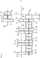
- Figure 1 shows schematically the wheel set of a manual transmission for motor vehicles.
- the manual transmission has an input shaft 10, which can be connected on a drive or motor side 1 to a drive or motor of the motor vehicle, not shown here, preferably via a clutch.
- An output shaft 30 is arranged parallel to the input shaft 10. Furthermore, the gearbox has an additional shaft 50, which is also arranged parallel to the input shaft 10.
- the fixed gear 11 meshes with an idler gear 31 which is arranged on the first output shaft 30. Further idler gears, namely idler gears 32, 33, 34, 35 and 36, are seated on the output shaft 30.
- the idler gear 31 can be connected to the output shaft 30 in a rotationally fixed manner via a gear shift clutch 37 designed as a double gear shift clutch.
- the double-gear shift clutch 37 has a sliding sleeve 38 which, starting from a neutral position, can be moved axially along the output shaft 30 in the direction of the idler gear 31 and in the direction of the idler gear 32.
- the sliding sleeve 38 is displaced in the direction of the idler gear 31, a rotationally fixed connection can be established between the idler gear 31 and the output shaft 30.
- the idler gear 31 is assigned to a first forward gear I of the manual transmission.
- the first (forward) gear I can thus be engaged.
- the torque of the motor leads via the input shaft 10 and the gear pairing of the gears 11, 31 to the output shaft 30, on which a first pinion 39 sits in a rotationally fixed manner.
- the first pinion 39 is in meshing engagement with an only partially illustrated ring gear 2 of an output (not shown).
- a second gear II of the manual transmission can be engaged.
- the torque flow then takes place from the engine via the fixed gear 12 and the idler gear 32 meshing therewith onto the output shaft 30.
- a further double gear shift clutch 40 by means of which a third forward gear III and a fourth forward gear IV can be engaged, in a manner analogous to that of the double gear shift clutch 37.
- another double gear shift clutch 41 also on the output shaft 30 is another double gear shift clutch 41, through which either the idler gear 35 is assigned to a fifth forward gear V, or the idler gear 36, which is assigned to a sixth forward gear VI, can be connected in a rotationally fixed manner to the output shaft 30. Due to the position of the release wheels 31 to 36, which are all seated on the output shaft 30, the double-gear clutches 37, 40 and 41 are all located on the output shaft 30. In an alternative embodiment, some of the release wheels could also be arranged on the input shaft 10 be, which would then also have a corresponding arrangement of gear shift clutches on the input shaft.
- an additional gear 51, a second pinion 52 and an additional gear shift clutch 53 are arranged as a single gear shift clutch.
- the gear shift clutch 53 has a sliding sleeve 54 which can assume a neutral position and a shift position. In the switching position, it ensures a rotationally fixed connection between the second pinion 52 and the additional gear 51.
- the second pinion 52 meshes with the ring gear 2 like the first pinion 39. This meshing engagement is shown by the dotted line 3.
- the additional gear 51 meshes with the idler gear 31 of the first forward gear I (see dashed line 4).
- the second pinion 52 can be understood as an idler gear of a reverse gear R of the manual transmission. If the reverse gear R is engaged (or the sliding sleeve 54 is in the shift position), the torque flow runs from the motor via the gearwheels 11, 31 to the additional gearwheel 51. Since the second pinion 52 is non-rotatably connected to the additional gearwheel 51 when reverse gear R is engaged transfer the torque from the motor to the ring gear 2 and thus to the output.
- Figure 2 shows a first embodiment of the arrangement of the sliding sleeve 54 and the second pinion 52 on the additional shaft 50.
- components or features that become components or features of the Figure 1 are similar, designated by the same reference numerals. The same applies analogously to the other figures.
- the additional shaft 50 and the additional gear 51 are integrally formed here.
- the second pinion 52 is arranged in the axial direction of the additional shaft 50 between the additional gear 51 and the sliding sleeve 54. Seen in the radial direction, a needle bearing 55 is provided between the additional shaft 50 and the second pinion 52.
- a rotationally fixed connection between the sliding sleeve 54 and the additional shaft 50 takes place via a hub 56.
- a coupling ring 57 which has a conical contact surface 58, is fastened in a rotationally fixed manner to the second pinion 52. This conical contact surface 58 interacts with a synchronizer ring 59.
- the sliding sleeve 54 When engaging reverse gear R, the sliding sleeve 54, which in Figure 2 is shown in its neutral position, shifted in the direction of the coupling ring 57.
- the synchronizer ring 59 is pressed against the contact surface 58.
- the interaction of the synchronizer ring 59 and the thrust surface 58 brings the second pinion 52 to the speed of the additional shaft 50.
- the sliding sleeve 54 can be pushed into the switching position via the external toothing of the synchronizing ring 59 and the external toothing of the coupling ring 57. This creates a rotationally fixed connection between the coupling ring 57 and the hub 56.
- Figure 3 shows a second embodiment of the arrangement of sliding sleeve 54 and second pinion 52.
- sliding sleeve 54 and auxiliary gear 51 are arranged on the same axial side of the second pinion 52.
- Both the auxiliary gear 51 and the sliding sleeve 54 are located on a side of the second pinion 52 facing away from the engine side 1.
- a radial web which bridges the radial distance between an external toothing 61 of the additional gear 51 and a tooth base 62, comprises an axial projection 63, which extends towards the motor side 1.
- An external toothing 64 is incorporated into the projection 63. This external toothing 64 forms an serration connection with an internal toothing of the sliding sleeve 54, which ensures a rotationally fixed connection of the sliding sleeve 54 and the additional gear 51.
- the sliding sleeve 54 can, however, from the in Figure 3 Move the position shown to the right (to the motor side) to engage reverse gear R.
- the second pinion 52 and the coupling ring 57 form a unit, the axial width of which is determined by the external toothing 65 of the pinion 52 and the axial extent of the coupling ring 57 with its contact surface 58.
- the external toothing 65 is flush with the unit consisting of pinion 52 and clutch ring 57, viewed in the axial direction.
- auxiliary gear 51 is in meshing engagement with only one other gear (here idler gear 31).
- the additional shaft 50 can thus be assigned to exactly one gear of the manual transmission, namely here the reverse gear R.
- the exemplary embodiments according to FIG Figures 2 and 3 be equivalent.
- the vibration system consists of an identical pinion or gear with a coupling ring welded to it.
- the clutch ring 57 on the right i.e. on the engine side
- the clutch ring 57 on the left is attached to the pinion 52.
- the underlying vibration system comprises the auxiliary shaft 50 with the auxiliary gear 51, the hub 56 and the sliding sleeve 54 (see Figure 2 ). It has been shown, however, that when the gearbox is considered as a whole with regard to rattling, advantages result from the invention, although the moment of inertia of the sliding sleeve now contributes to the moment of inertia of the vibration system for excitation by the idler gear 31 (with 1 forward gear engaged).
Landscapes
- Engineering & Computer Science (AREA)
- General Engineering & Computer Science (AREA)
- Mechanical Engineering (AREA)
- Structure Of Transmissions (AREA)
- Connection Of Motors, Electrical Generators, Mechanical Devices, And The Like (AREA)
Description
- Die Erfindung betrifft ein Schaltgetriebe für ein Kraftfahrzeug, das eine Eingangswelle, eine Ausgangswelle sowie Festräder, Losräder und Gangschaltkupplungen zur drehfesten Verbindung der Losräder mit der Eingangswelle oder der Ausgangswelle umfasst.
- Ein derartiges Schaltgetriebe ist beispielsweise aus der
EP 0 560 202 B1 bekannt. Das Schaltgetriebe weist sechs Vorwärtsgänge und einen Rückwärtsgang auf. Jedem Gang kann dabei ein Losrad und eine Gangschaltkupplung zugeordnet werden, wobei das Losrad durch die Gangschaltkupplung drehfest mit der das Losrad tragenden Welle verbunden ist, wenn der entsprechende Gang eingelegt ist. Beispielsweise kämmt bei einem Ausführungsbeispiel derEP 0 560 202 B1 ein auf der Ausgangswelle angeordnetes Losrad eines ersten Vorwärtsgang mit einem Festrad auf der Eingangswelle. Die dem ersten Gang (erste Vorwärtsgang) zugeordnete Gangschaltkupplung ist Teil einer Doppelgangschaltkupplung, mit der auch ein Losrad eines zweiten Vorwärtsgang drehfest mit der Ausgangswelle verbunden werden kann. - Ist die Eingangswelle über eine Kupplung mit einem Antrieb verbunden, so wird im Schaltgetriebe bei eingelegtem ersten Vorwärtsgang das Drehmoment von der Eingangswelle über die Zahnradpaarung Festrad / Losrad des ersten Vorwärtsgangs auf die Ausgangswelle übertragen. An einem Ende der Ausgangswelle sitzt drehfest ein erstes Ritzel, das mit einem Ringrad eines Abtriebs (hier ein Differenzial) kämmt. Somit ist eine geschlossene Drehmomentkette zwischen Antrieb und Abtrieb gegeben.
- Zur Realisierung eines Rückwärtsgangs weist das Schaltgetriebe der
EP 0 560 202 B1 eine Zusatzwelle mit einem darauf sitzenden zweiten Ritzel auf, das ebenfalls mit dem Ringrad kämmt. Auf der Zusatzwelle sind zudem ein Zusatzzahnrad und eine Zusatz-Gangschaltkupplung angeordnet. Die Zusatz-Gangschaltkupplung weist dabei eine Schiebemuffe auf, die sich axial verschieben lässt. Die Schiebemuffe sorgt bei eingelegtem Rückwärtsgang für eine drehfeste Verbindung zwischen dem Zusatzzahnrad und dem zweiten Ritzel. Das Zusatzzahnrad der Zusatzwelle kann daher auch als Losrad des Rückwärtsgangs bezeichnet werden. Da das Zusatzzahnrad über das Losrad des ersten Ganges angetrieben wird, kann das Losrad des ersten Ganges als Zwischenrad angesehen werden, durch das die erforderliche Drehrichtungsumkehr gegenüber dem ersten Gang erreicht wird. - Die
JP 2004-176844 - Die
JP 2010-203605 A - Bei der Schaltgetriebe der
DE 101 45 790 A1 lässt sich über eine Schaltmuffe ein mit dem Ringrad kämmendes Ritzel mit der Zusatzwelle drehfest verbinden bzw. wieder lösen. Bei eingelegtem Rückwärtsgang verläuft der Drehmomentfluss von der Eingangswelle des Schaltgetriebes über eine gesonderte Zwischenwelle, die keine direkte Anbindung an das Ringrad aufweist. - Im Betrieb des Schaltgetriebes kann es zu unerwünschtes Rasselgeräuschen kommen. Durch Torsionsschwingungen insbesondere induziert durch den Antrieb können Zahnflanken von lastfreien Zahnrädern, die miteinander kämmen, innerhalb des gegebenen Zahnflankenspiels aneinander anschlagen, was zu den unerwünschten Rasselgeräuschen führt. Ist beispielsweise der erste Vorwärtsgang eingelegt, so läuft das lastfreie Losrad des Rückwärtsgangs aufgrund des gegebenen kämmenden Eingriffs mit dem Losrad des ersten Vorwärtsgangs mit und kann die besagten Rasselgeräusche (mit-)verursachen.
- Der Erfindung liegt die Aufgabe zu Grunde, ein Schaltgetriebe gemäß dem Oberbegriff von Anspruch 1 so weiterzuentwickeln, dass Rasselgeräusche möglichst vermieden bzw. klein gehalten werden. Das Schaltgetriebe sollte zudem möglichst einfach und kompakt aufgebaut sein.
- Die der Erfindung zu Grunde liegende Aufgabe wird mit einem Schaltgetriebe gemäß Anspruch 1 gelöst. Ausführungsbeispiele der Erfindung können den Unteransprüchen entnommen werden.
- Beim erfindungsgemäßen Schaltgetriebe ist das zweite Ritzel bei nicht eingelegtem Zusatzgang drehbar auf der Zusatzwelle angeordnet und bei eingelegtem Zusatzgang mit der Zusatzwelle drehfest verbunden. Somit besteht bei nicht eingelegtem Zusatzgang eine Entkopplung zwischen der Zusatzwelle und dem zweiten Ritzel. Aufgrund des kämmenden Eingriffs mit dem Ringrad dreht sich das zweite Ritzel immer dann, wenn das Kraftfahrzeug in Bewegung ist. Bei Torsionsschwingungen, die über den Anregungspfad des Ringrads zur Zusatzwelle gelangen, führt die entsprechende Entkopplung der Zusatzwelle von dem zweiten Ritzel zu einem kleineren Trägheitsmoment des Schwingungssystems, das über diesen Anregungspfad angeregt werden kann. Die Idee der Erfindung besteht also darin, gezielt Einfluss zu nehmen auf die rotierende Masse bzw. das Trägheitsmoment des rotierenden Systems, das über die Anregung des Ringrads in Schwingungen versetzt werden kann und dabei unerwünschte Rasselgeräusche erzeugt.
- Erfindungsgemäß lässt sich die Schiebemuffe bei nicht eingelegtem Zusatzgang zum zweiten Ritzel verdrehen. Bei eingelegtem Zusatzgang hingegen ist die Schiebemuffe mit dem zweiten Ritzel drehfest verbunden. Insbesondere die Schiebemuffe trägt zum Trägheitsmoment des oben erwähnten rotierenden, über das Ringrad anregbaren Systems bei, weil bei der Schiebemuffe die rotierende Masse bei relativ großem Durchmesser anfällt.
- Das Zusatzzahnrad sitzt als Festrad auf der Zusatzwelle. Entsprechend ist das Zusatzzahnrad einstückig mit der Zusatzwelle ausgebildet. Alternativ sind Zusatzzahnrad und Zusatzwelle separate Bauteile, die - unabhängig von jeglichen Schaltzuständen im Getriebe - drehfest miteinander verbunden sind.
- Die Schiebemuffe kann drehfest mit dem Zusatzzahnrad verbunden sein. In diesem Fall würde die Schiebemuffe zum Trägheitsmoment des Schwingungssystems beitragen, dem auch das Zusatzzahnrad angehört. Auch dieses Schwingungssystem kann zu Rasselgeräuschen führen, doch hat sich gezeigt, dass eine schwingungstechnische Entkopplung von zweitem Ritzel und zumindest der Schiebemuffe insgesamt zu besseren Ergebnissen hinsichtlich Rasseln führt.
- Erfindungsgemäß ist der Zusatzgang als Rückwärtsgang ausgebildet. Das Zusatzzahnrad kämmt mit einem Losrad auf der Ausgangswelle. Das mit dem Zusatzzahnrad kämmende Losrad ist dem ersten Vorwärtsgang des Schaltgetriebes zugeordnet. Eine andere erfindungsgemäße Möglichkeit besteht darin, dass das Zusatzzahnrad mit einem Losrad eines zweiten Vorwärtsgangs kämmt. Das Losrad des ersten Vorwärtsgangs kann mit einem Festrad auf der Eingangswelle kämmen, das vorzugsweise einstückig mit der Eingangswelle ausgebildet ist. Alternativ oder zusätzlich kann das Losrad des zweiten Vorwärtsgangs mit einem (weiteren) auf der Eingangswelle angeordneten Festrad auf der Eingangswelle kämmen, wobei auch hier das Festrad einstückig mit der Eingangswelle ausgebildet sein kann.
- In einem nicht beanspruchten Ausführungsbeispiel kann der Zusatzgang alternativ auch als Vorwärtsgang ausgebildet sein. Beispielsweise ist es denkbar, den Zusatzgang als sogenannten Kriechgang mit einer sehr hohen Übersetzung auszubilden. In diesem Fall bedarf es keiner Maßnahmen zur Drehrichtungsumkehr gegenüber den übrigen Vorwärtsgängen des Schaltgetriebes. Sollte bei dem Ausführungsbeispiel des Kriechgangs der Antrieb des Zusatzzahnrads auch über ein Losrad eines Vorwärtsgangs erfolgen, wäre dann aber noch ein Zwischenrad notwendig.
- Das Schaltgetriebe kann als Doppelkupplungsgetriebe ausgebildet sein, welches neben der Eingangswelle eine weitere Eingangswelle aufweist. Vorzugsweise sind die Eingangswellen zueinander koaxial angeordnet, wobei eine der Eingangswellen als Hohlwelle und die andere als Vollwelle ausgebildet sein kann.
- Auch kann das Schaltgetriebe eine weitere Ausgangswelle aufweisen, auf der ein weiteres Ritzel angeordnet ist, das ebenfalls mit dem Ringrad kämmt. In der Ausführung von zwei Ausgangswellen würde somit das Ringrad mit drei Ritzeln kämmen, nämlich mit den Ritzeln der beiden Ausgangswellen sowie mit dem zweiten Ritzel auf der Zusatzwelle.
- In einem Ausführungsbeispiel sind die Schiebemuffe an einer axialen Seite des zweiten Ritzels und das Zusatzzahnrad an einer gegenüber liegenden axialen Seite des zweiten Ritzels angeordnet. Von einer Antriebs- oder Motorseite des Schaltgetriebes her gesehen kann sich somit in axialer Richtung der Zusatzwelle folgende Reihenfolge ergeben: Schiebemuffe, zweites Ritzel, Zusatzzahnrad. Somit ist das zweite Ritzel zwischen Schiebemuffe und Zusatzzahnrad angeordnet, wobei es bei der Beurteilung der relativen Lage der Bauteile zueinander auf die jeweilige Außenverzahnung von Ritzel und Zusatzzahnrad ankommen soll.
- Alternativ zur Ausführung, bei der das zweite Ritzel zwischen Zusatzzahnrad und Schiebemuffe sitzt, können Schiebemuffe und Zusatzzahnrad an einer gleichen axialen Seite des zweiten Ritzels angeordnet sein.
- Insbesondere, wenn das zweite Ritzel zwischen Zusatzzahnrad und Schiebemuffe angeordnet ist, kann eine Nabe vorgesehen sein. Vorzugsweise ist diese Nabe über eine Kerbverzahnung mit der Zusatzwelle drehfest verbunden. Die Schiebemuffe umfasst in radialer Richtung diese Nabe, wobei zwischen Schiebemuffe und Nabe ebenfalls Mittel vorgesehen sind, durch die eine drehfeste Verbindung zwischen Nabe und Schiebemuffe sichergestellt wird. Gegenüber der Nabe ist jedoch die Schiebemuffe axial verschiebbar.
- Die Schiebemuffe kann an einem Radialsteg des Zusatzzahnrads angeordnet sein. Der Radialsteg des Zusatzzahnrads überbrückt dabei den radialen Abstand zwischen der Außenverzahnung des Zusatzzahnrads und der Zahnradachse, um die sich das Zusatzzahnrad dreht. Die Anordnung der Schiebemuffe an dem Radialsteg des Zusatzzahnrads stellt eine mögliche Ausführung dar, wenn Zusatzzahnrad und Schiebemuffe an einer gleichen Seite des zweiten Ritzels angeordnet sind.
- Eine drehbare Lagerung zwischen dem zweiten Ritzel und der Schiebemuffe der Zusatz-Gangschaltkupplung kann ein Nadellager umfassen. Beispielsweise kann das Nadellager zwischen dem zweiten Ritzel und der Zusatzwelle angeordnet sein, wobei dann das Zusatzzahnrad als Festrad drehfest auf der Zusatzwelle sitzt.
- An dem zweiten Ritzel kann drehfest ein Kupplungsring befestigt sein. Eine bevorzugte Befestigung stellt hierbei das Laserschweißen dar.
- In einem Ausführungsbeispiel entspricht eine Breite der Außenverzahnung im Wesentlichen der Gesamtbreite des zweiten Ritzels. Das zweite Ritzel kann dabei einen kleinen axialen Ansatz aufweisen, der zur drehfesten Befestigung des Kupplungsrings dient. Insbesondere weist das zweite Ritzel darüber hinaus keine axial sich erstreckenden Flächen zur drehbaren Lagerung weiterer Bauteil auf.
- Anhand der in den Figuren dargestellten Ausführungsbeispiele wird die Erfindung näher erläutert. Es zeigen:
- Figur 1
- schematisch ein erfindungsgemäßes Schaltgetriebe im Längsschnitt;
- Figur 2
- eine erste Ausführung der Anordnung von einer Schiebemuffe und einem zweiten Ritzel auf einer Zusatzwelle; und
- Figur 3
- eine zweite Ausführung der Anordnung von Schiebemuffe und zweitem Ritzel auf der Zusatzwelle;
-
Figur 1 zeigt schematisch den Radsatz eines Schaltgetriebes für Kraftfahrzeuge. Das Schaltgetriebe weist eine Eingangswelle 10 auf, die sich an einer Antriebs- oder Motorseite 1 mit einem hier nicht dargestellten Antrieb oder Motor des Kraftfahrzeugs vorzugsweise über eine Kupplung verbinden lässt. - Parallel zur Eingangswelle 10 ist eine Ausgangswelle 30 angeordnet. Des Weiteren weist das Schaltgetriebe eine Zusatzwelle 50 auf, die ebenfalls parallel zur Eingangswelle 10 angeordnet ist.
- Auf der Eingangswelle 10 sind sechs Festräder 11, 12, 13, 14, 15 und 16 angeordnet. Das Festrad 11 kämmt dabei mit einem Losrad 31, welches auf der ersten Ausgangswelle 30 angeordnet ist. Auf der Ausgangswelle 30 sitzen weitere Losräder, nämlich Losräder 32, 33, 34, 35 und 36. Das Losrad 31 lässt sich über eine als Doppel-Gangschaltkupplung ausgebildete Gangschaltkupplung 37 drehfest mit der Ausgangswelle 30 verbinden. Die Doppel-Gangschaltkupplung 37 weist dabei eine Schiebemuffe 38 auf, die sich ausgehend von einer Neutralposition entlang der Ausgangswelle 30 in Richtung des Losrads 31 und in Richtung des Losrads 32 axial bewegen lässt. Wird die Schiebemuffe 38 in Richtung des Losrads 31 verschoben, lässt sich dadurch eine drehfeste Verbindung zwischen Losrad 31 und Ausgangswelle 30 herstellen. Das Losrad 31 ist dabei einem ersten Vorwärtsgang I des Schaltgetriebes zugeordnet. Durch Betätigung der Schiebemuffe 38 lässt sich somit der erste (Vorwärts-)Gang I einlegen. Das Drehmoment des Motors führt dabei über die Eingangswelle 10 und die Zahnradpaarung der Zahnräder 11, 31 auf die Ausgangswelle 30, auf der drehfest ein erstes Ritzel 39 sitzt. Das erste Ritzel 39 steht dabei im kämmenden Eingriff mit einem nur teilsweise dargestellten Ringrads 2 eines Abtriebs (nicht dargestellt).
- Mit einer axialen Verschiebung der Schiebemuffe 38 von der Neutralstellung in Richtung des Losrads 32 lässt sich ein zweiter Gang II des Schaltgetriebes einlegen. Bei eingelegtem zweiten Gang II erfolgt der Drehmomentfluss dann vom Motor über das Festrad 12 und das damit kämmende Losrad 32 auf die Ausgangswelle 30.
- Zwischen den Rädern 33, 34 ist eine weitere Doppel-Gangschaltkupplung 40 angeordnet, durch die sich, in analoger Weise wie bei der Doppel-Gangschaltkupplung 37, ein dritter Vorwärtsgang III und einen vierter Vorwärtsgang IV einlegen lässt. Ebenfalls auf der Ausgangswelle 30 sitzt eine weitere Doppel-Gangschaltkupplung 41, durch die entweder das Losrad 35, das einem fünften Vorwärtsgang V zugeordnet ist, oder das Losrad 36, dass einem sechsten Vorwärtsgang VI zugeordnet ist, drehfest mit der Ausgangswelle 30 verbunden werden kann. Bedingt durch die Lage der Lösräder 31 bis 36, die alle auf der Ausgangswelle 30 sitzen, befinden sich auch die Doppel-Gangschaltkupplungen 37, 40 und 41 allesamt auf der Ausgangswelle 30. Bei einer alternativen Ausführung könnten auch einige der Lösräder auf der Eingangswelle 10 angeordnet sein, was dann auch eine entsprechende Anordnung von Gangsschaltkupplungen auf der Eingangswelle zu Folge hätte.
- Auf der Zusatzwelle 50 sind ein Zusatzzahnrad 51, ein zweites Ritzel 52 und eine als Einfach-Gangschaltkupplung ausgebildete Zusatzgangschaltkupplung 53 (kurz: Gangschaltkupplung 53) angeordnet. Die Gangschaltkupplung 53 weist eine Schiebemuffe 54 auf, die in Neutralposition und eine Schaltposition einnehmen kann. In Schaltposition sorgt sie für eine drehfeste Verbindung zwischen dem zweiten Ritzel 52 und dem Zusatzzahnrad 51. Das zweite Ritzel 52 kämmt wie das erste Ritzel 39 mit dem Ringrad 2. Dieser kämmende Eingriff ist durch die gepunktete Linie 3 dargestellt.
- Das Zusatzzahnrad 51 kämmt mit dem Losrad 31 des ersten Vorwärtsgangs I (siehe gestrichelte Linie 4). Das zweite Ritzel 52 kann als Losrad eines Rückwärtsgangs R des Schaltgetriebes aufgefasst werden. Ist der Rückwärtsgang R eingelegt (oder befindet sich die Schiebemuffe 54 in Schaltposition), so verläuft der Drehmomentfluss vom Motor über die Zahnräder 11, 31 zum Zusatzzahnrad 51. Da das zweite Ritzel 52 bei eingelegtem Rückwärtsgang R drehfest mit dem Zusatzzahnrad 51 verbunden ist, wird das Drehmoment vom Motor auf das Ringrad 2 und somit auf den Abtrieb übertragen.
-
Figur 2 zeigt eine erste Ausführung der Anordnung von der Schiebemuffe 54 und dem zweiten Ritzel 52 auf der Zusatzwelle 50. InFigur 2 werden Bauteile oder Merkmale, die zu Bauteilen oder Merkmalen derFigur 1 ähnlich sind, mit gleichen Bezugszeichen bezeichnet. Sinngemäß gilt das auch für die übrigen Figuren. - Die Zusatzwelle 50 und das Zusatzzahnrad 51 sind hier einstückig ausgebildet. Das zweite Ritzel 52 ist in axialer Richtung der Zusatzwelle 50 gesehen zwischen dem Zusatzzahnrad 51 und der Schiebemuffe 54 angeordnet. In radialer Richtung gesehen ist zwischen der Zusatzwelle 50 und dem zweiten Ritzel 52 ein Nadellager 55 vorgesehen. Eine drehfeste Verbindung zwischen der Schiebemuffe 54 und der Zusatzwelle 50 erfolgt über eine Nabe 56. An dem zweiten Ritzel 52 ist ein Kupplungsring 57 drehfest befestigt, der eine konische Anlauffläche 58 aufweist. Diese konische Anlauffläche 58 wirkt mit einem Synchronring 59 zusammen. Beim Einlegen des Rückwärtsgangs R wird die Schiebemuffe 54, die in
Figur 2 in ihrer Neutralposition dargestellt ist, in Richtung des Kupplungsrings 57 verschoben. Dabei wird der Synchronring 59 gegen die Anlauffläche 58 gedrückt. Durch das Zusammenwirken von Synchronring 59 und Anlauffläche 58 wird das zweite Ritzel 52 auf die Drehzahl der Zusatzwelle 50 gebracht. Ist eine Synchronisation der Drehzahlen von Zusatzwelle 50 und zweitem Ritzel erreicht, lässt sich die Schiebemuffe 54 über die Außenverzahnung des Synchronrings 59 und die Außenverzahnung des Kupplungsring 57 in die Schaltposition schieben. Dadurch wird eine drehfeste Verbindung zwischen Kupplungsring 57 und der Nabe 56 erzeugt. -
Figur 3 zeigt eine zweite Ausführung der Anordnung von Schiebemuffe 54 und zweitem Ritzel 52. Im Gegensatz zum Ausführungsbeispiel derFigur 2 sind Schiebemuffe 54 und Zusatzzahnrad 51 an einer gleichen axialen Seite des zweiten Ritzel 52 angeordnet. Sowohl das Zusatzzahnrad 51 als auch die Schiebemuffe 54 befinden sich an einer der Motorseite 1 abgewandten Seite des zweiten Ritzels 52. - Ein Radialsteg, der den radialen Abstand zwischen einer Außenverzahnung 61 des Zusatzzahnrads 51 und eines Zahnfußes 62 überbrückt, umfasst einen axialen Vorsprung 63, der sich zur Motorseite 1 hin erstreckt. In den Vorsprung 63 ist eine Außenverzahnung 64 eingearbeitet ist. Diese Außenverzahnung 64 bildet mit einer Innenverzahnung der Schiebemuffe 54 eine Kerbzahnverbindung, die für eine drehfeste Verbindung von Schiebemuffe 54 und Zusatzzahnrad 51 sorgt. Die Schiebemuffe 54 lässt sich aber von der in
Figur 3 dargestellten Position nach rechts (zur Motorseite) verschieben, um den Rückwärtsgang R einzulegen. - Das zweite Ritzel 52 und der Kupplungsring 57 bilden eine Einheit, dessen axiale Breite durch die Außenverzahnung 65 des Ritzels 52 und die axiale Erstreckung des Kupplungsrings 57 mit seiner Anlauffläche 58 bestimmt ist. An der dem Kupplungsring abgewandten axialen Seite des zweiten Ritzels 52 schließt die Außenverzahnung 65 in axialer Richtung gesehen bündig mit der Einheit bestehend aus Ritzel 52 und Kupplungsring 57 ab.
- Die Ausführungsbeispiele der Figuren haben gemeinsam, dass neben dem zweiten Ritzel 52, das mit dem Ringrad 2 kämmt, nur ein weiteres Zahnrad (Zusatzzahnrad 51), das mit nur einem anderen Zahnrad (hier Losrad 31) in kämmenden Eingriff steht. Somit kann die Zusatzwelle 50 genau einem Gang des Schaltgetriebes zugeordnet werden, nämlich hier dem Rückwärtsgang R.
- Bezüglich der rotierenden Massen bzw. des Trägheitsmoments des Schwingungssystems, das (bei nicht eingelegtem Rückwärtsgang) durch eine Anregung über das Ringrad 2 Rasselgeräusche verursachen könnte, dürften die Ausführungsbeispiele gemäß der
Figuren 2 und3 gleichwertig sein. In beiden Fällen besteht das Schwingungssystem aus einem baugleichen Ritzel oder Zahnrad mit einem daran angeschweißten Kupplungsring. Ein Unterschied besteht darin, dass beiFigur 2 der Kupplungsring 57 rechts (also motorseitig) und beiFigur 3 der Kupplungsring 57 links (von der Motorseite 1 abgewandt) an dem Ritzel 52 befestigt ist. - Bei einer Anregung über das Losrad 31 umfasst das zu Grunde zu legende Schwingungssystem hingegen die Zusatzwelle 50 mit dem Zusatzrad 51, die Nabe 56 sowie die Schiebemuffe 54 (siehe
Figur 2 ). Es hat sich aber gezeigt, dass bei Gesamtbetrachtung des Schaltgetriebes hinsichtlich Rasseln sich durch die Erfindung Vorteile ergeben, gleichwohl nun das Trägheitsmoment der Schiebemuffe zum Trägheitsmoment des Schwingungssystems beiträgt, dass bei Anregung durch das Losrad 31 (bei eingelegtem 1 Vorwärtsgang) zu Grunde zu legen ist. -
- 1
- Antriebs- oder Motorseite
- 2
- Ringrad
- 3
- gestrichelte Linie (kämmender Eingriff)
- 4
- gestrichelte Linie (kämmender Eingriff)
- 10
- Eingangswelle
- 11
- Festrad
- 12
- Festrad
- 13
- Festrad
- 14
- Festrad
- 15
- Festrad
- 16
- Festrad
- 30
- Ausgangswelle
- 31
- Losrad
- 32
- Losrad
- 33
- Losrad
- 34
- Losrad
- 35
- Losrad
- 36
- Losrad
- 37
- Gangschaltkupplung (Doppel-Gangschaltkupplung)
- 38
- Schiebemuffe
- 39
- erstes Ritzel
- 40
- Gangschaltkupplung (Doppel-Gangschaltkupplung)
- 41
- Gangschaltkupplung (Doppel-Gangschaltkupplung)
- 50
- Zusatzwelle
- 51
- Zusatzzahnrad
- 52
- zweites Ritzel
- 53
- Zusatzgangschaltkupplung (Einfach-Gangschaltkupplung)
- 54
- Schiebemuffe
- 55
- Nadellager
- 56
- Nabe
- 57
- Kupplungsring
- 58
- Anlauffläche
- 59
- Synchronring
- 60
- Radialsteg
- 61
- Außenverzahnung
- 62
- Zahnfuß
- 63
- axialer Vorsprung
- 64
- Außenverzahnung
- 65
- Außenverzahnung
Claims (6)
- Schaltgetriebe für ein Kraftfahrzeug, umfassend:- eine Eingangswelle (10) und eine Ausgangswelle (30),- Festräder (11 bis 16), Losräder (31 bis 36) sowie Gangschaltkupplungen (37, 40, 41) zur drehfesten Verbindung der Losräder (31 bis 36) mit der Eingangswelle (10) oder der Ausgangswelle (30),- mehrere Gänge (I bis VI), wobei jedem Gang eines der Losräder (31 bis 36) und eine der Gangschaltkupplungen (37, 40, 41) zugeordnet sind, wobei das Losrad durch die Gangschaltkupplung drehfest mit der das Losrad tragenden Welle verbunden ist, wenn der entsprechende Gang eingelegt ist,- ein Ringrad (2), das mit einem ersten Ritzel (39) kämmt, das auf der Ausgangswelle (30) angeordnet ist,- eine Zusatzwelle (50), auf der ein zweites Ritzel (52), das mit dem Ringrad (2) kämmt, sowie ein Zusatzzahnrad (51) und eine Zusatz-Gangschaltkupplung (53) angeordnet ist,wobei die Zusatzwelle (50) und die Zusatz-Gangschaltkupplung (53) einem Zusatzgang zugeordnet sind, wobei das zweite Ritzel (52) bei nicht eingelegtem Zusatzgang drehbar auf der Zusatzwelle (50) angeordnet ist und bei eingelegtem Zusatzgang mit der Zusatzwelle drehfest verbunden ist, wobei der Zusatzgang ein Rückwärtsgang (R) ist, wobei das Zusatzzahnrad (51) als Festrad drehfest auf der Zusatzwelle (50) sitzt und mit einem Losrad (31) auf der Ausgangswelle (30) kämmt, wobei eine Schiebemuffe (54) der Zusatz-Gangschaltkupplung bei nicht eingelegtem Zusatzgang zum zweiten Ritzel (52) verdrehbar ist und bei eingelegtem Zusatzgang mit dem zweiten Ritzel (52) drehfest verbunden ist
dadurch gekennzeichnet, dass das Losrad (31), mit dem das Zusatzzahnrad (51) kämmt, einem ersten Vorwärtsgang (I) oder einem zweiten Vorwärtsgang (II) des Schaltgetriebes zugeordnet ist. - Schaltgetriebe nach Anspruch 1, dadurch gekennzeichnet, dass die Schiebemuffe (54) an einer axialen Seite des zweiten Ritzels (52) und das Zusatzzahnrad (51) an einer gegenüber liegenden axialen Seite des zweiten Ritzels (52) angeordnet sind.
- Schaltgetriebe nach Anspruch 1 oder 2, dadurch gekennzeichnet, dass zwischen der Zusatzwelle (50) und der Schiebemuffe (54) eine Nabe (56) vorgesehen ist.
- Schaltgetriebe nach Anspruch 1, dadurch gekennzeichnet, dass die Schiebemuffe (54) an einem Radialsteg (60) des Zusatzzahnrads (51) angeordnet ist.
- Schaltgetriebe nach einem der Ansprüche 1 bis 4, dadurch gekennzeichnet, dass eine drehbare Lagerung zwischen dem zweiten Ritzel (52) und der Schiebemuffe (54) der Zusatz-Gangschaltkupplung (53) ein Nadellager (55) umfasst, das zwischen dem Ritzel (52) und der Zusatzwelle (50) angeordnet ist.
- Schaltgetriebe nach einem der Ansprüche 1 bis 5, dadurch gekennzeichnet, dass ein Kupplungsring (57) drehfest mit dem zweiten Ritzel (52) verbunden ist.
Applications Claiming Priority (2)
| Application Number | Priority Date | Filing Date | Title |
|---|---|---|---|
| DE102014114006.0A DE102014114006A1 (de) | 2014-09-26 | 2014-09-26 | Schaltgetriebe für ein Kraftfahrzeug |
| PCT/EP2015/071966 WO2016046313A1 (de) | 2014-09-26 | 2015-09-24 | Schaltgetriebe für ein kraftfahrzeug |
Publications (2)
| Publication Number | Publication Date |
|---|---|
| EP3198170A1 EP3198170A1 (de) | 2017-08-02 |
| EP3198170B1 true EP3198170B1 (de) | 2020-02-12 |
Family
ID=54199647
Family Applications (1)
| Application Number | Title | Priority Date | Filing Date |
|---|---|---|---|
| EP15771074.0A Active EP3198170B1 (de) | 2014-09-26 | 2015-09-24 | Schaltgetriebe für ein kraftfahrzeug |
Country Status (5)
| Country | Link |
|---|---|
| EP (1) | EP3198170B1 (de) |
| CN (1) | CN106715962B (de) |
| BR (1) | BR112017005837A2 (de) |
| DE (1) | DE102014114006A1 (de) |
| WO (1) | WO2016046313A1 (de) |
Families Citing this family (1)
| Publication number | Priority date | Publication date | Assignee | Title |
|---|---|---|---|---|
| EP4008932B1 (de) * | 2020-12-04 | 2023-11-15 | Ningbo Geely Automobile Research & Development Co. Ltd. | Getriebe |
Family Cites Families (6)
| Publication number | Priority date | Publication date | Assignee | Title |
|---|---|---|---|---|
| DE4207989A1 (de) * | 1992-03-13 | 1993-09-16 | Ford Werke Ag | Mehrgaengiges wechselgetriebe fuer kraftfahrzeuge |
| DE10145790A1 (de) * | 2001-07-15 | 2003-12-24 | Richard Boisch | Kurzbauende Lastschaltgetriebe |
| JP2004176844A (ja) * | 2002-11-28 | 2004-06-24 | Fuji Heavy Ind Ltd | 歯車変速機 |
| CN2835707Y (zh) * | 2005-09-14 | 2006-11-08 | 重庆青山工业有限责任公司 | 一种全同步机械式变速器 |
| JP5277069B2 (ja) * | 2009-02-06 | 2013-08-28 | 本田技研工業株式会社 | トランスミッション |
| CN201651182U (zh) * | 2009-12-30 | 2010-11-24 | 浙江吉利汽车研究院有限公司 | 一种两轴式变速器的倒挡布置结构 |
-
2014
- 2014-09-26 DE DE102014114006.0A patent/DE102014114006A1/de not_active Withdrawn
-
2015
- 2015-09-24 BR BR112017005837A patent/BR112017005837A2/pt not_active IP Right Cessation
- 2015-09-24 WO PCT/EP2015/071966 patent/WO2016046313A1/de not_active Ceased
- 2015-09-24 CN CN201580052197.6A patent/CN106715962B/zh active Active
- 2015-09-24 EP EP15771074.0A patent/EP3198170B1/de active Active
Non-Patent Citations (1)
| Title |
|---|
| None * |
Also Published As
| Publication number | Publication date |
|---|---|
| WO2016046313A1 (de) | 2016-03-31 |
| CN106715962A (zh) | 2017-05-24 |
| EP3198170A1 (de) | 2017-08-02 |
| DE102014114006A1 (de) | 2016-03-31 |
| CN106715962B (zh) | 2020-09-04 |
| BR112017005837A2 (pt) | 2017-12-19 |
Similar Documents
| Publication | Publication Date | Title |
|---|---|---|
| DE102006058831B4 (de) | Mehrganggetriebe mit Differentialzahnradsatz und Vorgelegewellen-Zahnradanordnung | |
| DE102011076386B4 (de) | Doppelkupplungsgetriebe | |
| EP1714818B1 (de) | Doppelkupplungsgetriebe | |
| WO2012139877A1 (de) | Antriebsvorrichtung mit einer elektrischen maschine | |
| EP0248899B1 (de) | Stufenschaltgetriebe | |
| DE202016005407U1 (de) | Hybridgetriebe für ein Fahrzeug sowie ein Fahrzeug mit dem Hybridgetriebe | |
| EP2739878B1 (de) | Schaltgetriebe für ein kraftfahrzeug | |
| DE102012100536B4 (de) | Schaltgetriebe mit Zusatzgang | |
| DE102008001398A1 (de) | Automatisiertes Schaltgetriebe eines Kraftfahrzeugs | |
| DE102015223506B4 (de) | Planetengetriebe mit Gangschaltung durch Axialverschiebung des Planeten | |
| EP3211270B1 (de) | Doppelkupplungsgetriebe für kraftfahrzeuge | |
| DE102016001199B4 (de) | Antriebseinrichtung für ein Kraftfahrzeug | |
| EP3198170B1 (de) | Schaltgetriebe für ein kraftfahrzeug | |
| DE1930467A1 (de) | Kerbverzahnte Verbindung zwischen zwei Drehmoment uebertragenden Getriebeelementen | |
| DE102016111277A1 (de) | Doppelkupplungsgetriebe mit Brückenwelle | |
| DE102020005168B3 (de) | Doppelkupplungsgetriebe | |
| WO2018072893A1 (de) | Doppelkupplungsgetriebe mit brückenwelle | |
| DE102011121481A1 (de) | Schaltvorrichtung mit einem Drehfreilauf für die Schaltwelle und Kraftfahrzeug-Getriebe mit einer solchen Schaltvorrichtung | |
| DE102011016661A1 (de) | Doppelkupplungsgetriebe und Verfahren zu dessen Betreiben | |
| DE102016122706B3 (de) | Schaltgetriebe mit Ölpumpe | |
| DE102016210306A1 (de) | Hybridgetriebe für ein Fahrzeug, Verfahren sowie Fahrzeug mit dem Hybridgetriebe | |
| DE102017206836B4 (de) | Getriebe für ein Kraftfahrzeug | |
| DE102024002359B4 (de) | Schaltvorrichtung für Mehrganggetriebe für Fahrräder und Getriebeanordnungen mit einer solchen Schaltvorrichtung | |
| WO2015113660A1 (de) | Wechselgetriebe zur realisierung von zumindest acht vorwärtsgängen | |
| DE102022132459B4 (de) | Flexible mehrgängige Getriebevorrichtung für ein Kraftfahrzeug mit elektrifiziertem Antriebsstrang; sowie Antriebsstrang |
Legal Events
| Date | Code | Title | Description |
|---|---|---|---|
| STAA | Information on the status of an ep patent application or granted ep patent |
Free format text: STATUS: THE INTERNATIONAL PUBLICATION HAS BEEN MADE |
|
| PUAI | Public reference made under article 153(3) epc to a published international application that has entered the european phase |
Free format text: ORIGINAL CODE: 0009012 |
|
| STAA | Information on the status of an ep patent application or granted ep patent |
Free format text: STATUS: REQUEST FOR EXAMINATION WAS MADE |
|
| 17P | Request for examination filed |
Effective date: 20170426 |
|
| AK | Designated contracting states |
Kind code of ref document: A1 Designated state(s): AL AT BE BG CH CY CZ DE DK EE ES FI FR GB GR HR HU IE IS IT LI LT LU LV MC MK MT NL NO PL PT RO RS SE SI SK SM TR |
|
| AX | Request for extension of the european patent |
Extension state: BA ME |
|
| DAV | Request for validation of the european patent (deleted) | ||
| DAX | Request for extension of the european patent (deleted) | ||
| STAA | Information on the status of an ep patent application or granted ep patent |
Free format text: STATUS: EXAMINATION IS IN PROGRESS |
|
| 17Q | First examination report despatched |
Effective date: 20180307 |
|
| GRAP | Despatch of communication of intention to grant a patent |
Free format text: ORIGINAL CODE: EPIDOSNIGR1 |
|
| STAA | Information on the status of an ep patent application or granted ep patent |
Free format text: STATUS: GRANT OF PATENT IS INTENDED |
|
| RIC1 | Information provided on ipc code assigned before grant |
Ipc: F16H 3/089 20060101AFI20190829BHEP Ipc: F16H 3/08 20060101ALN20190829BHEP |
|
| INTG | Intention to grant announced |
Effective date: 20190923 |
|
| GRAS | Grant fee paid |
Free format text: ORIGINAL CODE: EPIDOSNIGR3 |
|
| GRAA | (expected) grant |
Free format text: ORIGINAL CODE: 0009210 |
|
| STAA | Information on the status of an ep patent application or granted ep patent |
Free format text: STATUS: THE PATENT HAS BEEN GRANTED |
|
| AK | Designated contracting states |
Kind code of ref document: B1 Designated state(s): AL AT BE BG CH CY CZ DE DK EE ES FI FR GB GR HR HU IE IS IT LI LT LU LV MC MK MT NL NO PL PT RO RS SE SI SK SM TR |
|
| REG | Reference to a national code |
Ref country code: GB Ref legal event code: FG4D Free format text: NOT ENGLISH |
|
| REG | Reference to a national code |
Ref country code: CH Ref legal event code: EP |
|
| REG | Reference to a national code |
Ref country code: AT Ref legal event code: REF Ref document number: 1232517 Country of ref document: AT Kind code of ref document: T Effective date: 20200215 |
|
| REG | Reference to a national code |
Ref country code: DE Ref legal event code: R096 Ref document number: 502015011718 Country of ref document: DE |
|
| REG | Reference to a national code |
Ref country code: IE Ref legal event code: FG4D Free format text: LANGUAGE OF EP DOCUMENT: GERMAN |
|
| REG | Reference to a national code |
Ref country code: RO Ref legal event code: EPE |
|
| PG25 | Lapsed in a contracting state [announced via postgrant information from national office to epo] |
Ref country code: FI Free format text: LAPSE BECAUSE OF FAILURE TO SUBMIT A TRANSLATION OF THE DESCRIPTION OR TO PAY THE FEE WITHIN THE PRESCRIBED TIME-LIMIT Effective date: 20200212 Ref country code: NO Free format text: LAPSE BECAUSE OF FAILURE TO SUBMIT A TRANSLATION OF THE DESCRIPTION OR TO PAY THE FEE WITHIN THE PRESCRIBED TIME-LIMIT Effective date: 20200512 Ref country code: RS Free format text: LAPSE BECAUSE OF FAILURE TO SUBMIT A TRANSLATION OF THE DESCRIPTION OR TO PAY THE FEE WITHIN THE PRESCRIBED TIME-LIMIT Effective date: 20200212 |
|
| REG | Reference to a national code |
Ref country code: LT Ref legal event code: MG4D |
|
| REG | Reference to a national code |
Ref country code: NL Ref legal event code: MP Effective date: 20200212 |
|
| PG25 | Lapsed in a contracting state [announced via postgrant information from national office to epo] |
Ref country code: SE Free format text: LAPSE BECAUSE OF FAILURE TO SUBMIT A TRANSLATION OF THE DESCRIPTION OR TO PAY THE FEE WITHIN THE PRESCRIBED TIME-LIMIT Effective date: 20200212 Ref country code: IS Free format text: LAPSE BECAUSE OF FAILURE TO SUBMIT A TRANSLATION OF THE DESCRIPTION OR TO PAY THE FEE WITHIN THE PRESCRIBED TIME-LIMIT Effective date: 20200612 Ref country code: LV Free format text: LAPSE BECAUSE OF FAILURE TO SUBMIT A TRANSLATION OF THE DESCRIPTION OR TO PAY THE FEE WITHIN THE PRESCRIBED TIME-LIMIT Effective date: 20200212 Ref country code: GR Free format text: LAPSE BECAUSE OF FAILURE TO SUBMIT A TRANSLATION OF THE DESCRIPTION OR TO PAY THE FEE WITHIN THE PRESCRIBED TIME-LIMIT Effective date: 20200513 Ref country code: HR Free format text: LAPSE BECAUSE OF FAILURE TO SUBMIT A TRANSLATION OF THE DESCRIPTION OR TO PAY THE FEE WITHIN THE PRESCRIBED TIME-LIMIT Effective date: 20200212 Ref country code: BG Free format text: LAPSE BECAUSE OF FAILURE TO SUBMIT A TRANSLATION OF THE DESCRIPTION OR TO PAY THE FEE WITHIN THE PRESCRIBED TIME-LIMIT Effective date: 20200512 |
|
| PG25 | Lapsed in a contracting state [announced via postgrant information from national office to epo] |
Ref country code: NL Free format text: LAPSE BECAUSE OF FAILURE TO SUBMIT A TRANSLATION OF THE DESCRIPTION OR TO PAY THE FEE WITHIN THE PRESCRIBED TIME-LIMIT Effective date: 20200212 |
|
| PG25 | Lapsed in a contracting state [announced via postgrant information from national office to epo] |
Ref country code: LT Free format text: LAPSE BECAUSE OF FAILURE TO SUBMIT A TRANSLATION OF THE DESCRIPTION OR TO PAY THE FEE WITHIN THE PRESCRIBED TIME-LIMIT Effective date: 20200212 Ref country code: EE Free format text: LAPSE BECAUSE OF FAILURE TO SUBMIT A TRANSLATION OF THE DESCRIPTION OR TO PAY THE FEE WITHIN THE PRESCRIBED TIME-LIMIT Effective date: 20200212 Ref country code: SM Free format text: LAPSE BECAUSE OF FAILURE TO SUBMIT A TRANSLATION OF THE DESCRIPTION OR TO PAY THE FEE WITHIN THE PRESCRIBED TIME-LIMIT Effective date: 20200212 Ref country code: PT Free format text: LAPSE BECAUSE OF FAILURE TO SUBMIT A TRANSLATION OF THE DESCRIPTION OR TO PAY THE FEE WITHIN THE PRESCRIBED TIME-LIMIT Effective date: 20200705 Ref country code: CZ Free format text: LAPSE BECAUSE OF FAILURE TO SUBMIT A TRANSLATION OF THE DESCRIPTION OR TO PAY THE FEE WITHIN THE PRESCRIBED TIME-LIMIT Effective date: 20200212 Ref country code: ES Free format text: LAPSE BECAUSE OF FAILURE TO SUBMIT A TRANSLATION OF THE DESCRIPTION OR TO PAY THE FEE WITHIN THE PRESCRIBED TIME-LIMIT Effective date: 20200212 Ref country code: SK Free format text: LAPSE BECAUSE OF FAILURE TO SUBMIT A TRANSLATION OF THE DESCRIPTION OR TO PAY THE FEE WITHIN THE PRESCRIBED TIME-LIMIT Effective date: 20200212 Ref country code: DK Free format text: LAPSE BECAUSE OF FAILURE TO SUBMIT A TRANSLATION OF THE DESCRIPTION OR TO PAY THE FEE WITHIN THE PRESCRIBED TIME-LIMIT Effective date: 20200212 |
|
| PGFP | Annual fee paid to national office [announced via postgrant information from national office to epo] |
Ref country code: RO Payment date: 20200911 Year of fee payment: 6 Ref country code: TR Payment date: 20200921 Year of fee payment: 6 |
|
| REG | Reference to a national code |
Ref country code: DE Ref legal event code: R097 Ref document number: 502015011718 Country of ref document: DE |
|
| PGFP | Annual fee paid to national office [announced via postgrant information from national office to epo] |
Ref country code: BE Payment date: 20200921 Year of fee payment: 6 |
|
| PLBE | No opposition filed within time limit |
Free format text: ORIGINAL CODE: 0009261 |
|
| STAA | Information on the status of an ep patent application or granted ep patent |
Free format text: STATUS: NO OPPOSITION FILED WITHIN TIME LIMIT |
|
| 26N | No opposition filed |
Effective date: 20201113 |
|
| PG25 | Lapsed in a contracting state [announced via postgrant information from national office to epo] |
Ref country code: SI Free format text: LAPSE BECAUSE OF FAILURE TO SUBMIT A TRANSLATION OF THE DESCRIPTION OR TO PAY THE FEE WITHIN THE PRESCRIBED TIME-LIMIT Effective date: 20200212 Ref country code: PL Free format text: LAPSE BECAUSE OF FAILURE TO SUBMIT A TRANSLATION OF THE DESCRIPTION OR TO PAY THE FEE WITHIN THE PRESCRIBED TIME-LIMIT Effective date: 20200212 |
|
| PG25 | Lapsed in a contracting state [announced via postgrant information from national office to epo] |
Ref country code: MC Free format text: LAPSE BECAUSE OF FAILURE TO SUBMIT A TRANSLATION OF THE DESCRIPTION OR TO PAY THE FEE WITHIN THE PRESCRIBED TIME-LIMIT Effective date: 20200212 |
|
| REG | Reference to a national code |
Ref country code: CH Ref legal event code: PL |
|
| PG25 | Lapsed in a contracting state [announced via postgrant information from national office to epo] |
Ref country code: LU Free format text: LAPSE BECAUSE OF NON-PAYMENT OF DUE FEES Effective date: 20200924 |
|
| PG25 | Lapsed in a contracting state [announced via postgrant information from national office to epo] |
Ref country code: CH Free format text: LAPSE BECAUSE OF NON-PAYMENT OF DUE FEES Effective date: 20200930 Ref country code: IE Free format text: LAPSE BECAUSE OF NON-PAYMENT OF DUE FEES Effective date: 20200924 Ref country code: LI Free format text: LAPSE BECAUSE OF NON-PAYMENT OF DUE FEES Effective date: 20200930 |
|
| REG | Reference to a national code |
Ref country code: AT Ref legal event code: MM01 Ref document number: 1232517 Country of ref document: AT Kind code of ref document: T Effective date: 20200924 |
|
| PG25 | Lapsed in a contracting state [announced via postgrant information from national office to epo] |
Ref country code: AT Free format text: LAPSE BECAUSE OF NON-PAYMENT OF DUE FEES Effective date: 20200924 |
|
| REG | Reference to a national code |
Ref country code: BE Ref legal event code: MM Effective date: 20210930 |
|
| PG25 | Lapsed in a contracting state [announced via postgrant information from national office to epo] |
Ref country code: RO Free format text: LAPSE BECAUSE OF NON-PAYMENT OF DUE FEES Effective date: 20210924 Ref country code: MT Free format text: LAPSE BECAUSE OF FAILURE TO SUBMIT A TRANSLATION OF THE DESCRIPTION OR TO PAY THE FEE WITHIN THE PRESCRIBED TIME-LIMIT Effective date: 20200212 Ref country code: CY Free format text: LAPSE BECAUSE OF FAILURE TO SUBMIT A TRANSLATION OF THE DESCRIPTION OR TO PAY THE FEE WITHIN THE PRESCRIBED TIME-LIMIT Effective date: 20200212 |
|
| PG25 | Lapsed in a contracting state [announced via postgrant information from national office to epo] |
Ref country code: MK Free format text: LAPSE BECAUSE OF FAILURE TO SUBMIT A TRANSLATION OF THE DESCRIPTION OR TO PAY THE FEE WITHIN THE PRESCRIBED TIME-LIMIT Effective date: 20200212 Ref country code: AL Free format text: LAPSE BECAUSE OF FAILURE TO SUBMIT A TRANSLATION OF THE DESCRIPTION OR TO PAY THE FEE WITHIN THE PRESCRIBED TIME-LIMIT Effective date: 20200212 |
|
| PG25 | Lapsed in a contracting state [announced via postgrant information from national office to epo] |
Ref country code: BE Free format text: LAPSE BECAUSE OF NON-PAYMENT OF DUE FEES Effective date: 20210930 |
|
| REG | Reference to a national code |
Ref country code: DE Ref legal event code: R081 Ref document number: 502015011718 Country of ref document: DE Owner name: FORD TRANSMISSIONS GMBH, DE Free format text: FORMER OWNER: GETRAG FORD TRANSMISSIONS GMBH, 50735 KOELN, DE |
|
| REG | Reference to a national code |
Ref country code: DE Ref legal event code: R082 Ref document number: 502015011718 Country of ref document: DE Representative=s name: PATENTANWAELTE BAUER VORBERG KAYSER PARTNERSCH, DE |
|
| PGFP | Annual fee paid to national office [announced via postgrant information from national office to epo] |
Ref country code: DE Payment date: 20250919 Year of fee payment: 11 |
|
| PGFP | Annual fee paid to national office [announced via postgrant information from national office to epo] |
Ref country code: IT Payment date: 20250923 Year of fee payment: 11 |
|
| PGFP | Annual fee paid to national office [announced via postgrant information from national office to epo] |
Ref country code: GB Payment date: 20250919 Year of fee payment: 11 |
|
| PGFP | Annual fee paid to national office [announced via postgrant information from national office to epo] |
Ref country code: FR Payment date: 20250922 Year of fee payment: 11 |