EP3198170B1 - Boîte de vitesses destinée à un véhicule automobile - Google Patents
Boîte de vitesses destinée à un véhicule automobile Download PDFInfo
- Publication number
- EP3198170B1 EP3198170B1 EP15771074.0A EP15771074A EP3198170B1 EP 3198170 B1 EP3198170 B1 EP 3198170B1 EP 15771074 A EP15771074 A EP 15771074A EP 3198170 B1 EP3198170 B1 EP 3198170B1
- Authority
- EP
- European Patent Office
- Prior art keywords
- gear
- additional
- pinion
- shaft
- sliding sleeve
- Prior art date
- Legal status (The legal status is an assumption and is not a legal conclusion. Google has not performed a legal analysis and makes no representation as to the accuracy of the status listed.)
- Active
Links
- 230000005540 biological transmission Effects 0.000 title claims description 32
- 230000008878 coupling Effects 0.000 claims description 18
- 238000010168 coupling process Methods 0.000 claims description 18
- 238000005859 coupling reaction Methods 0.000 claims description 18
- 230000005284 excitation Effects 0.000 description 6
- 230000007935 neutral effect Effects 0.000 description 4
- 241000219098 Parthenocissus Species 0.000 description 1
- 210000001520 comb Anatomy 0.000 description 1
- 238000006073 displacement reaction Methods 0.000 description 1
- 230000003993 interaction Effects 0.000 description 1
- 230000010355 oscillation Effects 0.000 description 1
- 239000007787 solid Substances 0.000 description 1
- 230000001360 synchronised effect Effects 0.000 description 1
- 238000003466 welding Methods 0.000 description 1
Images


Classifications
-
- F—MECHANICAL ENGINEERING; LIGHTING; HEATING; WEAPONS; BLASTING
- F16—ENGINEERING ELEMENTS AND UNITS; GENERAL MEASURES FOR PRODUCING AND MAINTAINING EFFECTIVE FUNCTIONING OF MACHINES OR INSTALLATIONS; THERMAL INSULATION IN GENERAL
- F16H—GEARING
- F16H3/00—Toothed gearings for conveying rotary motion with variable gear ratio or for reversing rotary motion
- F16H3/02—Toothed gearings for conveying rotary motion with variable gear ratio or for reversing rotary motion without gears having orbital motion
- F16H3/08—Toothed gearings for conveying rotary motion with variable gear ratio or for reversing rotary motion without gears having orbital motion exclusively or essentially with continuously meshing gears, that can be disengaged from their shafts
- F16H3/087—Toothed gearings for conveying rotary motion with variable gear ratio or for reversing rotary motion without gears having orbital motion exclusively or essentially with continuously meshing gears, that can be disengaged from their shafts characterised by the disposition of the gears
- F16H3/089—Toothed gearings for conveying rotary motion with variable gear ratio or for reversing rotary motion without gears having orbital motion exclusively or essentially with continuously meshing gears, that can be disengaged from their shafts characterised by the disposition of the gears all of the meshing gears being supported by a pair of parallel shafts, one being the input shaft and the other the output shaft, there being no countershaft involved
-
- F—MECHANICAL ENGINEERING; LIGHTING; HEATING; WEAPONS; BLASTING
- F16—ENGINEERING ELEMENTS AND UNITS; GENERAL MEASURES FOR PRODUCING AND MAINTAINING EFFECTIVE FUNCTIONING OF MACHINES OR INSTALLATIONS; THERMAL INSULATION IN GENERAL
- F16H—GEARING
- F16H3/00—Toothed gearings for conveying rotary motion with variable gear ratio or for reversing rotary motion
- F16H3/02—Toothed gearings for conveying rotary motion with variable gear ratio or for reversing rotary motion without gears having orbital motion
- F16H3/08—Toothed gearings for conveying rotary motion with variable gear ratio or for reversing rotary motion without gears having orbital motion exclusively or essentially with continuously meshing gears, that can be disengaged from their shafts
- F16H2003/0822—Toothed gearings for conveying rotary motion with variable gear ratio or for reversing rotary motion without gears having orbital motion exclusively or essentially with continuously meshing gears, that can be disengaged from their shafts characterised by the arrangement of at least one reverse gear
-
- F—MECHANICAL ENGINEERING; LIGHTING; HEATING; WEAPONS; BLASTING
- F16—ENGINEERING ELEMENTS AND UNITS; GENERAL MEASURES FOR PRODUCING AND MAINTAINING EFFECTIVE FUNCTIONING OF MACHINES OR INSTALLATIONS; THERMAL INSULATION IN GENERAL
- F16H—GEARING
- F16H2200/00—Transmissions for multiple ratios
- F16H2200/003—Transmissions for multiple ratios characterised by the number of forward speeds
- F16H2200/0052—Transmissions for multiple ratios characterised by the number of forward speeds the gear ratios comprising six forward speeds
Definitions
- the invention relates to a manual transmission for a motor vehicle, which comprises an input shaft, an output shaft and fixed gears, idler gears and gear shift clutches for the rotationally fixed connection of the idler gears to the input shaft or the output shaft.
- Such a manual transmission is for example from the EP 0 560 202 B1 known.
- the manual transmission has six forward gears and one reverse gear.
- An idler gear and a gear shift clutch can be assigned to each gear, the idler gear being non-rotatably connected to the shaft carrying the idler gear when the corresponding gear is engaged by the gear shift clutch.
- the combs in one embodiment EP 0 560 202 B1 an idler gear of a first forward gear arranged on the output shaft with a fixed gear on the input shaft.
- the gear shift clutch assigned to the first gear (first forward gear) is part of a double gear shift clutch, with which an idler gear of a second forward gear can also be connected to the output shaft in a rotationally fixed manner.
- the torque from the input shaft is set in the manual transmission when the first forward gear is engaged via the gear pair fixed gear / idler gear of the first Transfer forward gear to the output shaft.
- a first pinion which meshes with a ring gear of an output (here a differential). This creates a closed torque chain between the input and output.
- the manual transmission of EP 0 560 202 B1 an additional shaft with a second pinion on it, which also meshes with the ring gear.
- An additional gearwheel and an additional gear shift clutch are also arranged on the additional shaft.
- the additional gearshift clutch has a sliding sleeve that can be moved axially. When reverse gear is engaged, the sliding sleeve ensures a rotationally fixed connection between the additional gear and the second pinion.
- the additional gear of the additional shaft can therefore also be called the idler gear of the reverse gear. Since the additional gear is driven by the idler gear of the first gear, the idler gear of the first gear can be regarded as an intermediate gear, by means of which the required reversal of the direction of rotation compared to the first gear is achieved.
- the JP 2004-176844 discloses a manual transmission, the auxiliary gear and the second pinion meshing with the ring gear also being provided to form the reverse gear.
- the sliding sleeve of the additional gear shift clutch is axially displaceable, but arranged in a rotationally fixed manner on a hub, which in turn is connected in a rotationally fixed manner to the second pinion.
- the sliding sleeve creates a rotationally fixed connection between the second pinion and the additional gear.
- the JP 2010-203605 A discloses a manual transmission according to the preamble of claim 1.
- a further sliding sleeve is provided for realizing further forward gears.
- a pinion meshing with the ring gear can be connected to the additional shaft in a rotationally fixed manner or released again via a shift sleeve.
- reverse gear the torque flow from the input shaft of the gearbox runs over a separate intermediate shaft, which has no direct connection to the ring gear.
- Unwanted rattling noises can occur during operation of the gearbox. Torsional vibrations, in particular induced by the drive, can cause tooth flanks of load-free gearwheels, which mesh with one another, to strike one another within the given tooth flank play, which leads to the undesirable rattling noises. If, for example, the first forward gear is engaged, the load-free idler gear of the reverse gear will run with the meshing engagement with the idler gear of the first forward gear and can cause said rattling noises.
- the invention is based on the object of further developing a manual transmission in accordance with the preamble of claim 1 in such a way that rattling noises are avoided as far as possible or are kept small.
- the manual transmission should also be as simple and compact as possible.
- the second pinion is rotatably arranged on the additional shaft when the additional gear is not engaged and is connected in a rotationally fixed manner to the additional shaft when the additional gear is engaged.
- the second pinion rotates whenever the motor vehicle is in motion.
- the corresponding decoupling of the additional shaft from the second pinion leads to a smaller moment of inertia of the oscillation system, which can be excited via this excitation path.
- the idea of the invention is therefore to specifically influence the rotating mass or the moment of inertia of the rotating system, which can be caused to vibrate via the excitation of the ring gear and thereby generate undesirable rattling noises.
- the sliding sleeve can be turned to the second pinion when the additional gear is not engaged.
- the sliding sleeve is non-rotatably connected to the second pinion.
- the sliding sleeve contributes to the moment of inertia of the above-mentioned rotating system which can be excited via the ring gear, because the rotating mass occurs with a relatively large diameter in the sliding sleeve.
- the auxiliary gear sits as a fixed gear on the auxiliary shaft. Accordingly, the additional gear is formed in one piece with the additional shaft. Alternatively, the additional gear and the additional shaft are separate components that are connected to one another in a rotationally fixed manner, regardless of any switching states in the transmission.
- the sliding sleeve can be non-rotatably connected to the additional gear.
- the sliding sleeve would contribute to the moment of inertia of the vibration system, which also includes the additional gear.
- This vibration system can also lead to rattling noises, but it has been shown that vibration-related decoupling of the second pinion and at least the sliding sleeve leads overall to better results with regard to rattling.
- the additional gear is designed as a reverse gear.
- the additional gear meshes with an idler gear on the output shaft.
- the idler gear meshing with the additional gear is assigned to the first forward gear of the manual transmission.
- Another possibility according to the invention is that the additional gear meshes with an idler gear of a second forward gear.
- the idler gear of the first forward gear can mesh with a fixed gear on the input shaft, which is preferably in one piece with the Input shaft is formed.
- the idler gear of the second forward gear can mesh with a (further) fixed gear arranged on the input shaft on the input shaft, wherein the fixed gear can also be formed integrally with the input shaft.
- the additional gear can alternatively also be designed as a forward gear.
- the additional gear can alternatively also be designed as a forward gear.
- the additional gear it is conceivable to design the additional gear as a so-called crawl gear with a very high gear ratio. In this case, no measures are required to reverse the direction of rotation compared to the other forward gears of the manual transmission. If, in the exemplary embodiment of the creeper gear, the additional gearwheel is also driven via an idler gear of a forward gear, an intermediate gear would then still be necessary.
- the manual transmission can be designed as a double clutch transmission which, in addition to the input shaft, has a further input shaft.
- the input shafts are preferably arranged coaxially with one another, it being possible for one of the input shafts to be designed as a hollow shaft and the other as a solid shaft.
- the gearbox can also have a further output shaft on which a further pinion is arranged, which also meshes with the ring gear.
- the ring gear would thus mesh with three pinions, namely with the pinions of the two output shafts and with the second pinion on the additional shaft.
- the sliding sleeve is arranged on an axial side of the second pinion and the additional gearwheel on an opposite axial side of the second pinion. Seen from a drive or motor side of the gearbox, the following sequence can result in the axial direction of the additional shaft: sliding sleeve, second pinion, additional gear.
- the second pinion is thus arranged between the sliding sleeve and the additional gear, the respective external toothing of the pinion and the additional gear being important when assessing the relative position of the components with respect to one another.
- the sliding sleeve and the additional gear can be arranged on the same axial side of the second pinion.
- a hub can be provided.
- This hub is preferably non-rotatably connected to the additional shaft by means of serration.
- the sliding sleeve comprises this hub in the radial direction, and means are also provided between the sliding sleeve and the hub, by means of which a rotationally fixed connection between the hub and the sliding sleeve is ensured.
- the sliding sleeve is axially displaceable.
- the sliding sleeve can be arranged on a radial web of the additional gear.
- the radial web of the auxiliary gear spans the radial distance between the external toothing of the auxiliary gear and the gear axis about which the auxiliary gear rotates.
- the arrangement of the sliding sleeve on the radial web of the additional gear represents a possible one Execution if the additional gear and sliding sleeve are arranged on the same side of the second pinion.
- a rotatable mounting between the second pinion and the sliding sleeve of the additional gear shift clutch can comprise a needle bearing.
- the needle bearing can be arranged between the second pinion and the additional shaft, in which case the additional gearwheel is fixed on the additional shaft as a fixed gear.
- a coupling ring can be attached to the second pinion in a rotationally fixed manner.
- a preferred attachment here is laser welding.
- a width of the external toothing essentially corresponds to the overall width of the second pinion.
- the second pinion can have a small axial shoulder, which is used for the rotationally fixed fastening of the coupling ring.
- the second pinion also has no axially extending surfaces for the rotatable mounting of further components.
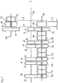
- Figure 1 shows schematically the wheel set of a manual transmission for motor vehicles.
- the manual transmission has an input shaft 10, which can be connected on a drive or motor side 1 to a drive or motor of the motor vehicle, not shown here, preferably via a clutch.
- An output shaft 30 is arranged parallel to the input shaft 10. Furthermore, the gearbox has an additional shaft 50, which is also arranged parallel to the input shaft 10.
- the fixed gear 11 meshes with an idler gear 31 which is arranged on the first output shaft 30. Further idler gears, namely idler gears 32, 33, 34, 35 and 36, are seated on the output shaft 30.
- the idler gear 31 can be connected to the output shaft 30 in a rotationally fixed manner via a gear shift clutch 37 designed as a double gear shift clutch.
- the double-gear shift clutch 37 has a sliding sleeve 38 which, starting from a neutral position, can be moved axially along the output shaft 30 in the direction of the idler gear 31 and in the direction of the idler gear 32.
- the sliding sleeve 38 is displaced in the direction of the idler gear 31, a rotationally fixed connection can be established between the idler gear 31 and the output shaft 30.
- the idler gear 31 is assigned to a first forward gear I of the manual transmission.
- the first (forward) gear I can thus be engaged.
- the torque of the motor leads via the input shaft 10 and the gear pairing of the gears 11, 31 to the output shaft 30, on which a first pinion 39 sits in a rotationally fixed manner.
- the first pinion 39 is in meshing engagement with an only partially illustrated ring gear 2 of an output (not shown).
- a second gear II of the manual transmission can be engaged.
- the torque flow then takes place from the engine via the fixed gear 12 and the idler gear 32 meshing therewith onto the output shaft 30.
- a further double gear shift clutch 40 by means of which a third forward gear III and a fourth forward gear IV can be engaged, in a manner analogous to that of the double gear shift clutch 37.
- another double gear shift clutch 41 also on the output shaft 30 is another double gear shift clutch 41, through which either the idler gear 35 is assigned to a fifth forward gear V, or the idler gear 36, which is assigned to a sixth forward gear VI, can be connected in a rotationally fixed manner to the output shaft 30. Due to the position of the release wheels 31 to 36, which are all seated on the output shaft 30, the double-gear clutches 37, 40 and 41 are all located on the output shaft 30. In an alternative embodiment, some of the release wheels could also be arranged on the input shaft 10 be, which would then also have a corresponding arrangement of gear shift clutches on the input shaft.
- an additional gear 51, a second pinion 52 and an additional gear shift clutch 53 are arranged as a single gear shift clutch.
- the gear shift clutch 53 has a sliding sleeve 54 which can assume a neutral position and a shift position. In the switching position, it ensures a rotationally fixed connection between the second pinion 52 and the additional gear 51.
- the second pinion 52 meshes with the ring gear 2 like the first pinion 39. This meshing engagement is shown by the dotted line 3.
- the additional gear 51 meshes with the idler gear 31 of the first forward gear I (see dashed line 4).
- the second pinion 52 can be understood as an idler gear of a reverse gear R of the manual transmission. If the reverse gear R is engaged (or the sliding sleeve 54 is in the shift position), the torque flow runs from the motor via the gearwheels 11, 31 to the additional gearwheel 51. Since the second pinion 52 is non-rotatably connected to the additional gearwheel 51 when reverse gear R is engaged transfer the torque from the motor to the ring gear 2 and thus to the output.
- Figure 2 shows a first embodiment of the arrangement of the sliding sleeve 54 and the second pinion 52 on the additional shaft 50.
- components or features that become components or features of the Figure 1 are similar, designated by the same reference numerals. The same applies analogously to the other figures.
- the additional shaft 50 and the additional gear 51 are integrally formed here.
- the second pinion 52 is arranged in the axial direction of the additional shaft 50 between the additional gear 51 and the sliding sleeve 54. Seen in the radial direction, a needle bearing 55 is provided between the additional shaft 50 and the second pinion 52.
- a rotationally fixed connection between the sliding sleeve 54 and the additional shaft 50 takes place via a hub 56.
- a coupling ring 57 which has a conical contact surface 58, is fastened in a rotationally fixed manner to the second pinion 52. This conical contact surface 58 interacts with a synchronizer ring 59.
- the sliding sleeve 54 When engaging reverse gear R, the sliding sleeve 54, which in Figure 2 is shown in its neutral position, shifted in the direction of the coupling ring 57.
- the synchronizer ring 59 is pressed against the contact surface 58.
- the interaction of the synchronizer ring 59 and the thrust surface 58 brings the second pinion 52 to the speed of the additional shaft 50.
- the sliding sleeve 54 can be pushed into the switching position via the external toothing of the synchronizing ring 59 and the external toothing of the coupling ring 57. This creates a rotationally fixed connection between the coupling ring 57 and the hub 56.
- Figure 3 shows a second embodiment of the arrangement of sliding sleeve 54 and second pinion 52.
- sliding sleeve 54 and auxiliary gear 51 are arranged on the same axial side of the second pinion 52.
- Both the auxiliary gear 51 and the sliding sleeve 54 are located on a side of the second pinion 52 facing away from the engine side 1.
- a radial web which bridges the radial distance between an external toothing 61 of the additional gear 51 and a tooth base 62, comprises an axial projection 63, which extends towards the motor side 1.
- An external toothing 64 is incorporated into the projection 63. This external toothing 64 forms an serration connection with an internal toothing of the sliding sleeve 54, which ensures a rotationally fixed connection of the sliding sleeve 54 and the additional gear 51.
- the sliding sleeve 54 can, however, from the in Figure 3 Move the position shown to the right (to the motor side) to engage reverse gear R.
- the second pinion 52 and the coupling ring 57 form a unit, the axial width of which is determined by the external toothing 65 of the pinion 52 and the axial extent of the coupling ring 57 with its contact surface 58.
- the external toothing 65 is flush with the unit consisting of pinion 52 and clutch ring 57, viewed in the axial direction.
- auxiliary gear 51 is in meshing engagement with only one other gear (here idler gear 31).
- the additional shaft 50 can thus be assigned to exactly one gear of the manual transmission, namely here the reverse gear R.
- the exemplary embodiments according to FIG Figures 2 and 3 be equivalent.
- the vibration system consists of an identical pinion or gear with a coupling ring welded to it.
- the clutch ring 57 on the right i.e. on the engine side
- the clutch ring 57 on the left is attached to the pinion 52.
- the underlying vibration system comprises the auxiliary shaft 50 with the auxiliary gear 51, the hub 56 and the sliding sleeve 54 (see Figure 2 ). It has been shown, however, that when the gearbox is considered as a whole with regard to rattling, advantages result from the invention, although the moment of inertia of the sliding sleeve now contributes to the moment of inertia of the vibration system for excitation by the idler gear 31 (with 1 forward gear engaged).
Landscapes
- Engineering & Computer Science (AREA)
- General Engineering & Computer Science (AREA)
- Mechanical Engineering (AREA)
- Structure Of Transmissions (AREA)
- Connection Of Motors, Electrical Generators, Mechanical Devices, And The Like (AREA)
Claims (6)
- Boîte de vitesses pour un véhicule automobile, comprenant :- un arbre d'entrée (10) et un arbre de sortie (30),- des roues fixes (11 à 16), des roues libres (31 à 36) ainsi que des embrayages (37, 40, 41) pour la liaison solidaire en rotation des roues libres (31 à 36) à l'arbre d'entrée (10) ou l'arbre de sortie (30),- plusieurs vitesses (I à VI), dans laquelle une des roues libres (31 à 36) et un des embrayages (37, 40, 41) sont associés à chaque vitesse, dans laquelle la roue libre est reliée par l'embrayage solidaire en rotation à l'arbre portant la roue libre, lorsque la vitesse correspondante est enclenchée,- une couronne (2), qui s'engrène avec un premier pignon (39), qui est agencé sur l'arbre de sortie (30),- un arbre supplémentaire (50), sur lequel est agencé un deuxième pignon (52), qui s'engrène avec la couronne (2), ainsi qu'une roue dentée supplémentaire (51) et un embrayage supplémentaire (53),dans laquelle l'arbre supplémentaire (50) et l'embrayage supplémentaire (53) sont associés à une vitesse supplémentaire, dans laquelle le deuxième pignon (52) est agencé en rotation sur l'arbre supplémentaire (50) lorsque la vitesse supplémentaire n'est pas enclenchée et est relié solidaire en rotation à l'arbre supplémentaire lorsque la vitesse supplémentaire est enclenchée, dans laquelle la vitesse supplémentaire est une marche arrière (R), dans laquelle la roue dentée supplémentaire (51) est située en tant que roue fixe solidaire en rotation sur l'arbre supplémentaire (50) et s'engrène avec une roue libre (31) sur l'arbre de sortie (30), dans laquelle un manchon coulissant (54) de l'embrayage supplémentaire est rotatif par rapport au deuxième pignon (52) lorsque la vitesse supplémentaire n'est pas enclenchée et est relié solidaire en rotation au deuxième pignon (52) lorsque la vitesse supplémentaire est enclenchée
caractérisée en ce que la roue libre (31), avec laquelle la roue dentée supplémentaire (51) s'engrène, est associée à une première marche avant (I) ou à une deuxième marche avant (II) de la boîte de vitesses. - Boîte de vitesses selon la revendication 1, caractérisée en ce que le manchon coulissant (54) est agencé au niveau d'un côté axial du deuxième pignon (52) et la roue dentée supplémentaire (51) est agencée au niveau d'un côté axial opposé du deuxième pignon (52).
- Boîte de vitesses selon la revendication 1 ou 2, caractérisée en ce qu'un moyeu (56) est prévu entre l'arbre supplémentaire (50) et le manchon coulissant (54).
- Boîte de vitesses selon la revendication 1, caractérisée en ce que le manchon coulissant (54) est agencé au niveau d'une nervure radiale (60) de la roue dentée supplémentaire (51).
- Boîte de vitesses selon l'une quelconque des revendications 1 à 4, caractérisée en ce qu'un palier rotatif entre le deuxième pignon (52) et le manchon coulissant (54) de l'embrayage supplémentaire (53) comprend un roulement à aiguilles (55), qui est agencé entre le pignon (52) et l'arbre supplémentaire (50).
- Boîte de vitesses selon l'une quelconque des revendications 1 à 5, caractérisée en ce qu'un anneau d'accouplement (57) est relié solidaire en rotation au deuxième pignon (52).
Applications Claiming Priority (2)
| Application Number | Priority Date | Filing Date | Title |
|---|---|---|---|
| DE102014114006.0A DE102014114006A1 (de) | 2014-09-26 | 2014-09-26 | Schaltgetriebe für ein Kraftfahrzeug |
| PCT/EP2015/071966 WO2016046313A1 (fr) | 2014-09-26 | 2015-09-24 | Boîte de vitesses destinée à un véhicule automobile |
Publications (2)
| Publication Number | Publication Date |
|---|---|
| EP3198170A1 EP3198170A1 (fr) | 2017-08-02 |
| EP3198170B1 true EP3198170B1 (fr) | 2020-02-12 |
Family
ID=54199647
Family Applications (1)
| Application Number | Title | Priority Date | Filing Date |
|---|---|---|---|
| EP15771074.0A Active EP3198170B1 (fr) | 2014-09-26 | 2015-09-24 | Boîte de vitesses destinée à un véhicule automobile |
Country Status (5)
| Country | Link |
|---|---|
| EP (1) | EP3198170B1 (fr) |
| CN (1) | CN106715962B (fr) |
| BR (1) | BR112017005837A2 (fr) |
| DE (1) | DE102014114006A1 (fr) |
| WO (1) | WO2016046313A1 (fr) |
Family Cites Families (6)
| Publication number | Priority date | Publication date | Assignee | Title |
|---|---|---|---|---|
| DE4207989A1 (de) | 1992-03-13 | 1993-09-16 | Ford Werke Ag | Mehrgaengiges wechselgetriebe fuer kraftfahrzeuge |
| DE10145790A1 (de) * | 2001-07-15 | 2003-12-24 | Richard Boisch | Kurzbauende Lastschaltgetriebe |
| JP2004176844A (ja) * | 2002-11-28 | 2004-06-24 | Fuji Heavy Ind Ltd | 歯車変速機 |
| CN2835707Y (zh) * | 2005-09-14 | 2006-11-08 | 重庆青山工业有限责任公司 | 一种全同步机械式变速器 |
| JP5277069B2 (ja) * | 2009-02-06 | 2013-08-28 | 本田技研工業株式会社 | トランスミッション |
| CN201651182U (zh) * | 2009-12-30 | 2010-11-24 | 浙江吉利汽车研究院有限公司 | 一种两轴式变速器的倒挡布置结构 |
-
2014
- 2014-09-26 DE DE102014114006.0A patent/DE102014114006A1/de not_active Withdrawn
-
2015
- 2015-09-24 WO PCT/EP2015/071966 patent/WO2016046313A1/fr active Application Filing
- 2015-09-24 EP EP15771074.0A patent/EP3198170B1/fr active Active
- 2015-09-24 BR BR112017005837A patent/BR112017005837A2/pt not_active IP Right Cessation
- 2015-09-24 CN CN201580052197.6A patent/CN106715962B/zh active Active
Non-Patent Citations (1)
| Title |
|---|
| None * |
Also Published As
| Publication number | Publication date |
|---|---|
| CN106715962B (zh) | 2020-09-04 |
| DE102014114006A1 (de) | 2016-03-31 |
| EP3198170A1 (fr) | 2017-08-02 |
| BR112017005837A2 (pt) | 2017-12-19 |
| CN106715962A (zh) | 2017-05-24 |
| WO2016046313A1 (fr) | 2016-03-31 |
Similar Documents
| Publication | Publication Date | Title |
|---|---|---|
| EP1714818B1 (fr) | Transmission à embrayage double | |
| DE102006058831B4 (de) | Mehrganggetriebe mit Differentialzahnradsatz und Vorgelegewellen-Zahnradanordnung | |
| DE102011076386B4 (de) | Doppelkupplungsgetriebe | |
| WO2012139877A1 (fr) | Dispositif d'entraînement comportant un moteur électrique | |
| EP0248899B1 (fr) | Boite de changement a echelonnement multiple de vitesses | |
| DE202016005407U1 (de) | Hybridgetriebe für ein Fahrzeug sowie ein Fahrzeug mit dem Hybridgetriebe | |
| EP3140141B1 (fr) | Agencement comprenant un train épicycloïdal et un dispositif de sélection d'un premier et d'un deuxième élément, et boîte de vitesse comprenant un tel agencement | |
| DE102015120818B4 (de) | Getriebe mit schaltbarem Planetensatz sowie Freilaufkupplung für ein elektrisch antreibbares Kraftfahrzeug | |
| EP3211270B1 (fr) | Boîte de vitesses à double embrayage pour véhicules automobiles | |
| EP2739878B1 (fr) | Boîte de vitesses pour un véhicule automobile | |
| DE102008001398A1 (de) | Automatisiertes Schaltgetriebe eines Kraftfahrzeugs | |
| DE102012100536B4 (de) | Schaltgetriebe mit Zusatzgang | |
| DE102015223506B4 (de) | Planetengetriebe mit Gangschaltung durch Axialverschiebung des Planeten | |
| DE1930467A1 (de) | Kerbverzahnte Verbindung zwischen zwei Drehmoment uebertragenden Getriebeelementen | |
| DE102020005168B3 (de) | Doppelkupplungsgetriebe | |
| EP3198170B1 (fr) | Boîte de vitesses destinée à un véhicule automobile | |
| WO2018072893A1 (fr) | Boîte de vitesses à double embrayage dotée d'un arbre de pontage | |
| EP2791524A1 (fr) | Dispositif de changement de vitesse pourvu d'une roue libre rotative pour l'arbre de changement de vitesse et boîte de vitesses pour véhicule à moteur pourvue d'un tel dispositif de changement de vitesse | |
| DE102016111277A1 (de) | Doppelkupplungsgetriebe mit Brückenwelle | |
| DE102016210306A1 (de) | Hybridgetriebe für ein Fahrzeug, Verfahren sowie Fahrzeug mit dem Hybridgetriebe | |
| DE102017206836B4 (de) | Getriebe für ein Kraftfahrzeug | |
| WO2015113660A1 (fr) | Boîte de vitesses à au moins huit vitesses avant | |
| DE102018221774A1 (de) | Doppelkupplungsgetriebe mit Windungsgängen und dritter Vorgelegewelle für Kriechladefunktion | |
| DE102018221849A1 (de) | Siebengang Frontquer-Doppelkupplungsgetriebe mit dritter Vorgelegewelle | |
| DE102021205938B4 (de) | Getriebe für einen Kraftfahrzeugantriebsstrang, Kraftfahrzeugantriebsstrang, umfassend ein solches Getriebe, sowie Verfahren zum Betreiben des Getriebes |
Legal Events
| Date | Code | Title | Description |
|---|---|---|---|
| STAA | Information on the status of an ep patent application or granted ep patent |
Free format text: STATUS: THE INTERNATIONAL PUBLICATION HAS BEEN MADE |
|
| PUAI | Public reference made under article 153(3) epc to a published international application that has entered the european phase |
Free format text: ORIGINAL CODE: 0009012 |
|
| STAA | Information on the status of an ep patent application or granted ep patent |
Free format text: STATUS: REQUEST FOR EXAMINATION WAS MADE |
|
| 17P | Request for examination filed |
Effective date: 20170426 |
|
| AK | Designated contracting states |
Kind code of ref document: A1 Designated state(s): AL AT BE BG CH CY CZ DE DK EE ES FI FR GB GR HR HU IE IS IT LI LT LU LV MC MK MT NL NO PL PT RO RS SE SI SK SM TR |
|
| AX | Request for extension of the european patent |
Extension state: BA ME |
|
| DAV | Request for validation of the european patent (deleted) | ||
| DAX | Request for extension of the european patent (deleted) | ||
| STAA | Information on the status of an ep patent application or granted ep patent |
Free format text: STATUS: EXAMINATION IS IN PROGRESS |
|
| 17Q | First examination report despatched |
Effective date: 20180307 |
|
| GRAP | Despatch of communication of intention to grant a patent |
Free format text: ORIGINAL CODE: EPIDOSNIGR1 |
|
| STAA | Information on the status of an ep patent application or granted ep patent |
Free format text: STATUS: GRANT OF PATENT IS INTENDED |
|
| RIC1 | Information provided on ipc code assigned before grant |
Ipc: F16H 3/089 20060101AFI20190829BHEP Ipc: F16H 3/08 20060101ALN20190829BHEP |
|
| INTG | Intention to grant announced |
Effective date: 20190923 |
|
| GRAS | Grant fee paid |
Free format text: ORIGINAL CODE: EPIDOSNIGR3 |
|
| GRAA | (expected) grant |
Free format text: ORIGINAL CODE: 0009210 |
|
| STAA | Information on the status of an ep patent application or granted ep patent |
Free format text: STATUS: THE PATENT HAS BEEN GRANTED |
|
| AK | Designated contracting states |
Kind code of ref document: B1 Designated state(s): AL AT BE BG CH CY CZ DE DK EE ES FI FR GB GR HR HU IE IS IT LI LT LU LV MC MK MT NL NO PL PT RO RS SE SI SK SM TR |
|
| REG | Reference to a national code |
Ref country code: GB Ref legal event code: FG4D Free format text: NOT ENGLISH |
|
| REG | Reference to a national code |
Ref country code: CH Ref legal event code: EP |
|
| REG | Reference to a national code |
Ref country code: AT Ref legal event code: REF Ref document number: 1232517 Country of ref document: AT Kind code of ref document: T Effective date: 20200215 |
|
| REG | Reference to a national code |
Ref country code: DE Ref legal event code: R096 Ref document number: 502015011718 Country of ref document: DE |
|
| REG | Reference to a national code |
Ref country code: IE Ref legal event code: FG4D Free format text: LANGUAGE OF EP DOCUMENT: GERMAN |
|
| REG | Reference to a national code |
Ref country code: RO Ref legal event code: EPE |
|
| PG25 | Lapsed in a contracting state [announced via postgrant information from national office to epo] |
Ref country code: FI Free format text: LAPSE BECAUSE OF FAILURE TO SUBMIT A TRANSLATION OF THE DESCRIPTION OR TO PAY THE FEE WITHIN THE PRESCRIBED TIME-LIMIT Effective date: 20200212 Ref country code: NO Free format text: LAPSE BECAUSE OF FAILURE TO SUBMIT A TRANSLATION OF THE DESCRIPTION OR TO PAY THE FEE WITHIN THE PRESCRIBED TIME-LIMIT Effective date: 20200512 Ref country code: RS Free format text: LAPSE BECAUSE OF FAILURE TO SUBMIT A TRANSLATION OF THE DESCRIPTION OR TO PAY THE FEE WITHIN THE PRESCRIBED TIME-LIMIT Effective date: 20200212 |
|
| REG | Reference to a national code |
Ref country code: LT Ref legal event code: MG4D |
|
| REG | Reference to a national code |
Ref country code: NL Ref legal event code: MP Effective date: 20200212 |
|
| PG25 | Lapsed in a contracting state [announced via postgrant information from national office to epo] |
Ref country code: SE Free format text: LAPSE BECAUSE OF FAILURE TO SUBMIT A TRANSLATION OF THE DESCRIPTION OR TO PAY THE FEE WITHIN THE PRESCRIBED TIME-LIMIT Effective date: 20200212 Ref country code: IS Free format text: LAPSE BECAUSE OF FAILURE TO SUBMIT A TRANSLATION OF THE DESCRIPTION OR TO PAY THE FEE WITHIN THE PRESCRIBED TIME-LIMIT Effective date: 20200612 Ref country code: LV Free format text: LAPSE BECAUSE OF FAILURE TO SUBMIT A TRANSLATION OF THE DESCRIPTION OR TO PAY THE FEE WITHIN THE PRESCRIBED TIME-LIMIT Effective date: 20200212 Ref country code: GR Free format text: LAPSE BECAUSE OF FAILURE TO SUBMIT A TRANSLATION OF THE DESCRIPTION OR TO PAY THE FEE WITHIN THE PRESCRIBED TIME-LIMIT Effective date: 20200513 Ref country code: HR Free format text: LAPSE BECAUSE OF FAILURE TO SUBMIT A TRANSLATION OF THE DESCRIPTION OR TO PAY THE FEE WITHIN THE PRESCRIBED TIME-LIMIT Effective date: 20200212 Ref country code: BG Free format text: LAPSE BECAUSE OF FAILURE TO SUBMIT A TRANSLATION OF THE DESCRIPTION OR TO PAY THE FEE WITHIN THE PRESCRIBED TIME-LIMIT Effective date: 20200512 |
|
| PG25 | Lapsed in a contracting state [announced via postgrant information from national office to epo] |
Ref country code: NL Free format text: LAPSE BECAUSE OF FAILURE TO SUBMIT A TRANSLATION OF THE DESCRIPTION OR TO PAY THE FEE WITHIN THE PRESCRIBED TIME-LIMIT Effective date: 20200212 |
|
| PG25 | Lapsed in a contracting state [announced via postgrant information from national office to epo] |
Ref country code: LT Free format text: LAPSE BECAUSE OF FAILURE TO SUBMIT A TRANSLATION OF THE DESCRIPTION OR TO PAY THE FEE WITHIN THE PRESCRIBED TIME-LIMIT Effective date: 20200212 Ref country code: EE Free format text: LAPSE BECAUSE OF FAILURE TO SUBMIT A TRANSLATION OF THE DESCRIPTION OR TO PAY THE FEE WITHIN THE PRESCRIBED TIME-LIMIT Effective date: 20200212 Ref country code: SM Free format text: LAPSE BECAUSE OF FAILURE TO SUBMIT A TRANSLATION OF THE DESCRIPTION OR TO PAY THE FEE WITHIN THE PRESCRIBED TIME-LIMIT Effective date: 20200212 Ref country code: PT Free format text: LAPSE BECAUSE OF FAILURE TO SUBMIT A TRANSLATION OF THE DESCRIPTION OR TO PAY THE FEE WITHIN THE PRESCRIBED TIME-LIMIT Effective date: 20200705 Ref country code: CZ Free format text: LAPSE BECAUSE OF FAILURE TO SUBMIT A TRANSLATION OF THE DESCRIPTION OR TO PAY THE FEE WITHIN THE PRESCRIBED TIME-LIMIT Effective date: 20200212 Ref country code: ES Free format text: LAPSE BECAUSE OF FAILURE TO SUBMIT A TRANSLATION OF THE DESCRIPTION OR TO PAY THE FEE WITHIN THE PRESCRIBED TIME-LIMIT Effective date: 20200212 Ref country code: SK Free format text: LAPSE BECAUSE OF FAILURE TO SUBMIT A TRANSLATION OF THE DESCRIPTION OR TO PAY THE FEE WITHIN THE PRESCRIBED TIME-LIMIT Effective date: 20200212 Ref country code: DK Free format text: LAPSE BECAUSE OF FAILURE TO SUBMIT A TRANSLATION OF THE DESCRIPTION OR TO PAY THE FEE WITHIN THE PRESCRIBED TIME-LIMIT Effective date: 20200212 |
|
| PGFP | Annual fee paid to national office [announced via postgrant information from national office to epo] |
Ref country code: RO Payment date: 20200911 Year of fee payment: 6 Ref country code: TR Payment date: 20200921 Year of fee payment: 6 |
|
| REG | Reference to a national code |
Ref country code: DE Ref legal event code: R097 Ref document number: 502015011718 Country of ref document: DE |
|
| PGFP | Annual fee paid to national office [announced via postgrant information from national office to epo] |
Ref country code: BE Payment date: 20200921 Year of fee payment: 6 |
|
| PLBE | No opposition filed within time limit |
Free format text: ORIGINAL CODE: 0009261 |
|
| STAA | Information on the status of an ep patent application or granted ep patent |
Free format text: STATUS: NO OPPOSITION FILED WITHIN TIME LIMIT |
|
| 26N | No opposition filed |
Effective date: 20201113 |
|
| PG25 | Lapsed in a contracting state [announced via postgrant information from national office to epo] |
Ref country code: SI Free format text: LAPSE BECAUSE OF FAILURE TO SUBMIT A TRANSLATION OF THE DESCRIPTION OR TO PAY THE FEE WITHIN THE PRESCRIBED TIME-LIMIT Effective date: 20200212 Ref country code: PL Free format text: LAPSE BECAUSE OF FAILURE TO SUBMIT A TRANSLATION OF THE DESCRIPTION OR TO PAY THE FEE WITHIN THE PRESCRIBED TIME-LIMIT Effective date: 20200212 |
|
| PG25 | Lapsed in a contracting state [announced via postgrant information from national office to epo] |
Ref country code: MC Free format text: LAPSE BECAUSE OF FAILURE TO SUBMIT A TRANSLATION OF THE DESCRIPTION OR TO PAY THE FEE WITHIN THE PRESCRIBED TIME-LIMIT Effective date: 20200212 |
|
| REG | Reference to a national code |
Ref country code: CH Ref legal event code: PL |
|
| PG25 | Lapsed in a contracting state [announced via postgrant information from national office to epo] |
Ref country code: LU Free format text: LAPSE BECAUSE OF NON-PAYMENT OF DUE FEES Effective date: 20200924 |
|
| PG25 | Lapsed in a contracting state [announced via postgrant information from national office to epo] |
Ref country code: CH Free format text: LAPSE BECAUSE OF NON-PAYMENT OF DUE FEES Effective date: 20200930 Ref country code: IE Free format text: LAPSE BECAUSE OF NON-PAYMENT OF DUE FEES Effective date: 20200924 Ref country code: LI Free format text: LAPSE BECAUSE OF NON-PAYMENT OF DUE FEES Effective date: 20200930 |
|
| REG | Reference to a national code |
Ref country code: AT Ref legal event code: MM01 Ref document number: 1232517 Country of ref document: AT Kind code of ref document: T Effective date: 20200924 |
|
| PG25 | Lapsed in a contracting state [announced via postgrant information from national office to epo] |
Ref country code: AT Free format text: LAPSE BECAUSE OF NON-PAYMENT OF DUE FEES Effective date: 20200924 |
|
| REG | Reference to a national code |
Ref country code: BE Ref legal event code: MM Effective date: 20210930 |
|
| PG25 | Lapsed in a contracting state [announced via postgrant information from national office to epo] |
Ref country code: RO Free format text: LAPSE BECAUSE OF NON-PAYMENT OF DUE FEES Effective date: 20210924 Ref country code: MT Free format text: LAPSE BECAUSE OF FAILURE TO SUBMIT A TRANSLATION OF THE DESCRIPTION OR TO PAY THE FEE WITHIN THE PRESCRIBED TIME-LIMIT Effective date: 20200212 Ref country code: CY Free format text: LAPSE BECAUSE OF FAILURE TO SUBMIT A TRANSLATION OF THE DESCRIPTION OR TO PAY THE FEE WITHIN THE PRESCRIBED TIME-LIMIT Effective date: 20200212 |
|
| PG25 | Lapsed in a contracting state [announced via postgrant information from national office to epo] |
Ref country code: MK Free format text: LAPSE BECAUSE OF FAILURE TO SUBMIT A TRANSLATION OF THE DESCRIPTION OR TO PAY THE FEE WITHIN THE PRESCRIBED TIME-LIMIT Effective date: 20200212 Ref country code: AL Free format text: LAPSE BECAUSE OF FAILURE TO SUBMIT A TRANSLATION OF THE DESCRIPTION OR TO PAY THE FEE WITHIN THE PRESCRIBED TIME-LIMIT Effective date: 20200212 |
|
| PG25 | Lapsed in a contracting state [announced via postgrant information from national office to epo] |
Ref country code: BE Free format text: LAPSE BECAUSE OF NON-PAYMENT OF DUE FEES Effective date: 20210930 |
|
| PGFP | Annual fee paid to national office [announced via postgrant information from national office to epo] |
Ref country code: IT Payment date: 20230927 Year of fee payment: 9 |
|
| REG | Reference to a national code |
Ref country code: DE Ref legal event code: R081 Ref document number: 502015011718 Country of ref document: DE Owner name: FORD TRANSMISSIONS GMBH, DE Free format text: FORMER OWNER: GETRAG FORD TRANSMISSIONS GMBH, 50735 KOELN, DE |
|
| PGFP | Annual fee paid to national office [announced via postgrant information from national office to epo] |
Ref country code: DE Payment date: 20240918 Year of fee payment: 10 |
|
| PGFP | Annual fee paid to national office [announced via postgrant information from national office to epo] |
Ref country code: GB Payment date: 20240920 Year of fee payment: 10 |
|
| PGFP | Annual fee paid to national office [announced via postgrant information from national office to epo] |
Ref country code: FR Payment date: 20240925 Year of fee payment: 10 |