EP3202575A2 - Presse rotative - Google Patents
Presse rotative Download PDFInfo
- Publication number
- EP3202575A2 EP3202575A2 EP16202330.3A EP16202330A EP3202575A2 EP 3202575 A2 EP3202575 A2 EP 3202575A2 EP 16202330 A EP16202330 A EP 16202330A EP 3202575 A2 EP3202575 A2 EP 3202575A2
- Authority
- EP
- European Patent Office
- Prior art keywords
- printing
- substrate
- forme cylinder
- actuator
- rotary printing
- Prior art date
- Legal status (The legal status is an assumption and is not a legal conclusion. Google has not performed a legal analysis and makes no representation as to the accuracy of the status listed.)
- Granted
Links
Images


Classifications
-
- B—PERFORMING OPERATIONS; TRANSPORTING
- B41—PRINTING; LINING MACHINES; TYPEWRITERS; STAMPS
- B41F—PRINTING MACHINES OR PRESSES
- B41F33/00—Indicating, counting, warning, control or safety devices
- B41F33/0081—Devices for scanning register marks
-
- B—PERFORMING OPERATIONS; TRANSPORTING
- B41—PRINTING; LINING MACHINES; TYPEWRITERS; STAMPS
- B41F—PRINTING MACHINES OR PRESSES
- B41F13/00—Common details of rotary presses or machines
- B41F13/08—Cylinders
- B41F13/10—Forme cylinders
- B41F13/12—Registering devices
- B41F13/14—Registering devices with means for displacing the cylinders
Definitions
- the invention relates to a rotary printing machine with at least one printing unit, in particular a web-fed rotary printing press.
- a printing unit of a rotary printing press for printing a printing substrate such as a printing material web usually has a forme cylinder for supporting a printing form arrangement for imaging at least one printed image on the printing substrate and for imaging at least two registration marks on the printing substrate adjacent to the printed image in the arrangement relationship adjacent to two in an axial direction Form cylinder opposite boundary edges of the substrate.
- the printing plate arrangement can be formed by a plurality of printing plates received on the forme cylinder.
- Conventional rotary printing presses, such as rotary printing presses for multicolor printing usually have a plurality of printing units for successively printing on the printing substrate.
- the width of the substrate (eg web width) in the axial direction of the forme cylinder can lead to different registration errors in the circumference.
- the registration errors can be caused on the one hand by errors in the plate production or the fixation of the plates on the forme cylinder and are therefore static in nature.
- the registration errors can result essentially from skews when exposing and bending the plates, from mechanical play and inaccuracies during plate loading or the plate tensioning device itself. In these cases, it can be assumed that an inclination or rotation of the relevant printing plate.
- dynamic errors may also play a role in registration errors, which may be due to differences in the web tension of a printing material web and thus may depend on a machine speed and the material properties of the printing substrate itself.
- Passercons can be used adjustments of a diagonal register and / or a slanted register of a rotary printing press.
- the checking of skews of the print image is currently performed by a machine operator himself, with the machine operator visually comparing the perimeter pegs near each of the boundary edges of the substrate. If deviations or peripheral register errors are visually recognized by the machine operator, this compensator performs an adjustment of the diagonal register in the corresponding printing unit and / or an adjustment of a guide roller in front of the first printing unit.
- the invention has for its object to provide a rotary printing machine, which allows for relief of a machine operator improved print quality and print stability.
- a rotary printing machine for printing a printing material, in particular a web-fed rotary printing press for printing a printing material web as printing material.
- the Rotary printing machine has at least one printing unit, at least one detection device, a control device and an adjusting device.
- the at least one printing unit comprises a forme cylinder for supporting a printing form arrangement for imaging at least one printed image on the printing substrate and for imaging at least two registration marks on the printing substrate adjacent to the at least one printed image adjacent to two boundary edges of the printing substrate opposite to one another in an axial direction of the forme cylinder.
- the detection device is set up to automatically detect the register marks on the printing material and to generate a detection signal for each registered register mark.
- the control device is connected to the detection device and configured to determine a circumferential registration error of the printed image on the substrate by comparing the detection signals for the register marks and to determine a compensation value for compensation of the circumferential registration error based on the circumferential registration error and to provide it as a control signal.
- the adjusting device is connected to the control device and arranged to automatically realize by means of at least one automatically controllable actuator based on the control signal to a related to the axial direction of the forme entanglement between the forme cylinder and the printing material to compensate for the circumferential registration error.
- the register marks which may be formed as color register marks, for example, and the automatic compensation of a possible circumferential registration error, ie by the constant automatic observation and modulation or compensation of Passerschwankept, with the rotary printing machine according to the invention at discharge of a machine operator improved print quality and Edition stability can be achieved.
- the at least one printing unit has a transfer cylinder for interacting with the forme cylinder and the printing material in order to transfer the at least one printed image to the printing substrate.
- the forme cylinder has a respective bearing journal on two longitudinal ends opposite in its axial direction, wherein the one bearing journal is mounted on a pivot bearing, so that the forme cylinder can be pivoted on the pivot bearing along a pressure direction relative to the transfer cylinder.
- an automatically controllable actuator of the actuator is arranged to pivot the forme cylinder to compensate for the circumferential registration error by a corresponding to the control signal swivel angle.
- the rotary printing machine also has a Beticianstoffleitwalze, which is arranged in a Beffystoff beyer vomiques the rotary printing machine before the at least one printing unit to guide the substrate before entering the at least one printing unit.
- the Bescherstoffleitwalze has at two in an axial direction of these opposite longitudinal ends in each case a bearing journal, wherein the one bearing journal is mounted on a pivot bearing, so that the Beyakstoffleitwalze is pivotable on the pivot bearing against the substrate.
- an automatically controllable actuator of the adjusting device is arranged to pivot the Be réellestoffleitwalze to compensate for the circumferential registration error by a corresponding to the control signal swivel angle.
- the at least one printing unit preferably forms a first printing location of the rotary printing press.
- each actuator of the actuator on a predetermined Binarystellweg wherein each actuator of the actuator in a zero position, which corresponds to a codessspasserenfin
- the detection means is adapted to detect the register marks on the substrate at a sampling rate of once per revolution of the forme cylinder, and arranged to detect a current machine acceleration of the rotary printing press with respect to the sampling rate of the register marks increased sampling rate.
- the control device is preferably set up to determine a current machine speed of the rotary printing press on the basis of the current machine acceleration and to take it into account in the compensation of the circumferential registration error.
- the rotary printing machine has a plurality of printing units designed as the at least one printing unit for successively printing on the printing material.
- the control device is set up to determine dead times for a registration of the register marks on the printing material caused by a transport of the printing material between the printing units and to take these into account in the compensation of the circumferential registration error.
- the forme cylinders of the printing units each have a predefined cylinder circumference, wherein the control device is set up, the dead times based on multiples of Cylinder circumferences to determine. With the multiples of the cylinder circumferences, a simple assumption can be made for dead zones between the printing units.
- FIGS. 1 to 6 a formed according to an embodiment of the invention rotary printing machine 1 for printing a printing substrate BS (see, eg Fig. 6 ) to be discribed.
- the rotary printing press 1 according to the present embodiment of the invention is designed in particular as a web-fed rotary printing press for printing on a printing material web such as a paper web as printing substrate BS.
- the rotary printing machine 1 has at least one printing unit 10 and an electronic control device 40.
- the rotary printing press 1 has more than the at least one printing unit 10 designed printing units 10, which are successively multi-colored printing of the printing substrate BS in a printing material passage LR of the rotary printing machine 1 are arranged one after the other.
- Each printing unit 10 includes a forme cylinder 11 for supporting a printing form assembly (not separately referred to) for imaging at least one print image on the substrate BS and for imaging a plurality of registration marks RM on the printing substrate BS adjacent to the at least one printed image in the registration relationship adjacent to two in an axial direction of the Form cylinder 11 opposite boundary edges of the printing substrate BS, as in Fig. 6 shown.
- the register marks RM are formed, for example, as color register marks.
- the printing plate assembly is formed in particular with a plurality of printing plates received on the forme cylinder 11.
- Each printing unit 10 also has a transfer cylinder 12 for cooperation with the forme cylinder 11 and the printing substrate BS to transfer the at least one printed image onto the printing substrate BS, and a counter-pressure cylinder 13 for interacting with the transfer cylinder 12.
- Each printing unit 10 has an operating side SI and a drive side SII.
- Each printing unit 10 is provided with an optical detection device 30, which is configured to automatically detect the register marks RM on the printing substrate BS and to generate a detection signal for each registered register mark RM.
- the register marks RM can be detected either by virtue of the width of the broadsheet page width BS being encompassed by at least one detection device 30 traversing approximately perpendicular to the printing material direction LR and / or by at least one arrangement comprising the width of the printing material broadsheet side width BS at least one detection device 30 is detected.
- circumferential register errors can be caused on the one hand by errors in the plate production or the fixation of the printing plates on the forme cylinder 11 and are therefore of a static nature.
- the circumferential registration errors can result essentially from skewing during exposure and bending of the printing plates, from mechanical play and inaccuracies during plate loading or the plate tensioning device itself. In these cases, it can be assumed that an inclination or rotation of the respective printing plates.
- circumferential registration errors dynamic effects may also play a role, which may be due to differences in the web tension of the printing substrate BS and thus may be dependent on a machine speed and the material properties of the printing substrate BS itself.
- the controller 40 is connected to each of the detectors 30 and configured to determine a circumferential register error of the print image on the substrate BS by comparing the detection signals for the register marks RM of each printing unit 10 based on the circumferential registration error To determine a compensation value for compensating the circumferential registration error and to provide it as a control signal.
- the rotary printing machine 1 has an adjusting device 50, which is connected to the control device 40 and which is set up, by means of automatically activatable actuators 51, 52 (see FIG Fig. 4 and Fig. 5 ) of the actuating device 50 based on the control signal automatically to realize a relation to the axial direction of the forme cylinder 11 of the respective printing unit 10 entanglement between the forme cylinder 11 and the substrate BS to compensate for the circumferential registration error.
- control device 50 can be implemented by means of hardware, firmware and / or software and will be explained in more detail below.
- a simulation model is implemented in the control device 50, which describes the aforementioned influencing variables and their effects.
- the simulation model is composed of two submodels, namely an interference model for the simulation of the slanted plate position or the "slanted pressure" and a compensation model for the elimination of interference by interleaving the printed image.
- an interference model for the simulation of the slanted plate position or the "slanted pressure”
- a compensation model for the elimination of interference by interleaving the printed image.
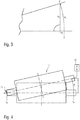
- the angle ⁇ zi represents an inclination of the printed image, as in Fig. 1 shown, and represents the angle ⁇ ui an entanglement of the forme cylinder 11 relative to the printing substrate BS or an entanglement of the printing substrate BS itself.
- a as in Fig. 2 shown coordinate system specified.
- the coordinates in the x-direction are oriented at the machine center in the axial direction of the forme cylinder 11, and the coordinates in the y-direction are based on a puncture (Sujetsweeping). Positive rotation angles are defined counterclockwise and negative rotation angles are clockwise. Since effective directions of the actuators 51, 52 of the actuator 50 may differ between different types of machines, a corresponding configuration of the respective direction of rotation is provided.
- the disturbance variable model will be described in more detail.
- the illustrated disturbance is not process-dependent for the simulation, but essentially considered as "production-related".
- the observed P x 0 ⁇ cos ⁇ z sin ⁇ z deviations must therefore only be calculated for parameter values that have already been set at the sampling time. The calculation of the deviations is carried out for the observation points j of all participating color separations i.
- Table 1 below lists possible simulation parameters for calculating disturbance variables: Table 1 parameter Type value range unit comment ⁇ zi disorder -1.0 ... 1.0 [Mrad] Changeable Process Disruption of Color Separation i X j job specification -1500 ... 1500 [Mm] Transverse position of the observation point j in the print control strip
- the compensation model is described in detail.
- the forme cylinder 11 as in Fig. 4 shown on one side pivotally mounted on a pivot bearing 11.1 and on the other side it is positioned via an automatically controllable actuator 51 (eg an adjusting motor) of the actuator 50 in the printing direction.
- an automatically controllable actuator 51 eg an adjusting motor
- the forme cylinder 11 at two longitudinal ends opposite in its axial direction in each case a bearing journal, wherein the one bearing journal is mounted on the pivot bearing 11.1, so that the forme cylinder 11 is pivotable on the pivot bearing 11.1 along the pressure direction relative to the transfer cylinder 12.
- the automatically controllable actuator 51 of the actuator 50 is arranged to pivot the forme cylinder 11 to compensate for the missionssspasserEffs by the corresponding to the control signal of the control device 40 pivot angle ⁇ u .
- Another way to compensate for the above-described disorder is to entangle the substrate formed as printing substrate BS before the pressure point considered.
- This method is preferably used on web-fed rotary printing presses before the first printing location of a printing material web. It is intervened by a one-sided pivotally mounted Beyakstoffleitwalze in the web and the web tension on one side "artificially".
- the rotary printing press 1 a Beffystoffleitwalze 20 which is arranged in Beffystoff takelaufraum LR of the rotary printing machine 1 in front of the viewed printing unit 10 in order to guide the substrate BS before entering the printing unit 10.
- the Beffystoffleitwalze 20 has at two in an axial direction of these opposite longitudinal ends in each case a bearing journal, wherein the one bearing journal is mounted on a pivot bearing 20.1, so that the Beffystoffleitwalze 20 is pivotable on the pivot bearing 20.1 relative to the substrate BS.
- an automatically controllable actuator 52 (such as an adjusting motor) of the adjusting device 50 is arranged to pivot the Bedgingstoffleitwalze 20 to compensate the civilsspasserEffs by a corresponding to the control signal of the control device 40 pivot angle ⁇ u .
- the considered printing unit 10 preferably forms a first printing location of the rotary printing press 1.
- Kp represents a parameterizable material property of the printing material.
- servomotors with a transmission are used for the above-mentioned actuators 51, 52 of the adjusting device 50, their behavior is purely integral.
- the current nominal position u r and the adjustment speed v a of the actuator 51, 52 are known.
- sat b a x ⁇ a . x > a b . x ⁇ b x . otherwise
- the gain k a is preferably set to 1 / T A.
- the longitudinal positions of the individual separations i of the defined observation points j are corrected on the basis of the current process parameters.
- Table 2 below lists possible simulation parameters for the compensation model.
- the parameter aM represents a current machine acceleration.
- each detection device 30 is set up to detect the register marks RM on the printing substrate BS at a sampling rate of once per revolution of the forme cylinder 11, and is set up with a current machine acceleration aM of the rotary printing press 1 relative to the scanning rate of the register marks RM increased sampling rate capture.
- the control device 40 is set up to determine a current machine speed v M of the rotary printing machine 1 on the basis of the current machine acceleration aM.
- Table 3 lists possible simulation parameters for the speed and the sampling time.
- Table 3 parameter Type value range unit comment U PZ installatorisch 500 ... 1500 [Mm] Form cylinder circumference a m process Instruction 0.1 ... 1 [m / s 2 ] acceleration Mr process Instruction 5 ... 20 [M / s] Speed setpoint t a installatorisch 10 ... 50 [Ms] sampling
- n i 1 + k M - D i ⁇ k D
- k M is the distance of the detection from the first printing location
- k D is the distance between the printing locations
- D i is the printing sequence index [0...] Of the corresponding printing location.
- control device 40 is set up to detect dead times caused by a transport of the printing substrate BS between the printing units 10 for a registration of the register marks RM on the printing substrate BS and to take these into account in the compensation of the circumferential registration error.
- control device 40 is set up to determine the dead times on the basis of multiples of the predefined cylinder circumferences (PZU) of the forme cylinders 11 of the printing units 10.
- Table 4 lists possible simulation parameters for transport times.
- the direction of action of the actuators 51, 52 is also dependent on the design implementation and may differ depending on the type and direction of the rotary printing press 1. In any case, it does not have to match the coordinate system chosen for the simulation. In order to avoid irritation, therefore, the effective directions (signs) should be predefined for the actuators 51, 52 as installation parameters. If no constructive differences of the pressure points (printing units 10) are to be expected among themselves, in principle sufficient indication of a sign for all actuators 51, 52 of the same type.
- the two submodels are superimposed in the simulation model in order to simulate the circumferential deviation visible on the printing substrate BS.
- each actuator 51, 52 of the actuator 50 has a predetermined Monstellweg and is in a zero position, which corresponds to a humanssspasserenfin strict stricture condition, set to a middle position of Intelstellweges to disturbances (disturbances of the rotation angle of the printed image) in both negative than to be able to compensate in the positive direction as well.
- control device 40 is advantageously set up such that each position of each actuator 51, 52 is optimized during the operating state so that each has the greatest possible distance to a respective actuator limit such as an end position or a stop.
- a respective actuator limit such as an end position or a stop.
Landscapes
- Engineering & Computer Science (AREA)
- Mechanical Engineering (AREA)
- Inking, Control Or Cleaning Of Printing Machines (AREA)
- Rotary Presses (AREA)
Applications Claiming Priority (1)
| Application Number | Priority Date | Filing Date | Title |
|---|---|---|---|
| DE102015121281.1A DE102015121281A1 (de) | 2015-12-07 | 2015-12-07 | Rotationsdruckmaschine |
Publications (3)
| Publication Number | Publication Date |
|---|---|
| EP3202575A2 true EP3202575A2 (fr) | 2017-08-09 |
| EP3202575A3 EP3202575A3 (fr) | 2017-10-04 |
| EP3202575B1 EP3202575B1 (fr) | 2018-09-12 |
Family
ID=57485398
Family Applications (1)
| Application Number | Title | Priority Date | Filing Date |
|---|---|---|---|
| EP16202330.3A Active EP3202575B1 (fr) | 2015-12-07 | 2016-12-06 | Presse rotative |
Country Status (3)
| Country | Link |
|---|---|
| EP (1) | EP3202575B1 (fr) |
| DE (1) | DE102015121281A1 (fr) |
| ES (1) | ES2693290T3 (fr) |
Family Cites Families (8)
| Publication number | Priority date | Publication date | Assignee | Title |
|---|---|---|---|---|
| US6199480B1 (en) * | 1992-06-06 | 2001-03-13 | Heideiberger Druckmaschinen | Arrangement for determining register deviations of a multicolor rotary printing machine |
| DE4235393A1 (de) * | 1992-10-21 | 1994-04-28 | Heidelberger Druckmasch Ag | Registerverstelleinrichtung an einer Bogendruckmaschine sowie Verfahren zur Registerverstellung |
| DE19830490A1 (de) * | 1997-11-18 | 1999-05-20 | Heidelberger Druckmasch Ag | Verfahren zur Passerregelung an einer Druckmaschine |
| US6796240B2 (en) * | 2001-06-04 | 2004-09-28 | Quad/Tech, Inc. | Printing press register control using colorpatch targets |
| DE10254836A1 (de) * | 2002-11-22 | 2004-06-17 | Windmöller & Hölscher Kg | Verfahren und Vorrichtung zur Regelung des Registers einer Druckmaschine |
| DE10261059B4 (de) * | 2002-12-24 | 2006-04-13 | Eltromat Gmbh | Verfahren und Vorrichtung zum Messen und Regeln eines Längs- und Seitenregisters sowie einer Druckbild-Parallelität eines Druckregisters in einer Mehrfarbendruckmaschine |
| DE10340569A1 (de) * | 2003-09-01 | 2005-04-07 | Koenig & Bauer Ag | Verfahren zur Reduktion von Passerfehlern auf einer in einer bahnverarbeitenden Vorrichtung und ein Druckwerk |
| DE102009028204A1 (de) * | 2009-08-04 | 2011-02-17 | Kba-Metronic Aktiengesellschaft | Diagonalregistereinstellvorrichtung |
-
2015
- 2015-12-07 DE DE102015121281.1A patent/DE102015121281A1/de not_active Withdrawn
-
2016
- 2016-12-06 EP EP16202330.3A patent/EP3202575B1/fr active Active
- 2016-12-06 ES ES16202330.3T patent/ES2693290T3/es active Active
Non-Patent Citations (1)
| Title |
|---|
| None |
Also Published As
| Publication number | Publication date |
|---|---|
| EP3202575A3 (fr) | 2017-10-04 |
| EP3202575B1 (fr) | 2018-09-12 |
| ES2693290T3 (es) | 2018-12-10 |
| DE102015121281A1 (de) | 2017-07-13 |
Similar Documents
| Publication | Publication Date | Title |
|---|---|---|
| DE3136703C1 (de) | Einrichtungen an Druckmaschinen mit Registerverstelleinrichtungen | |
| DE69201762T2 (de) | Siebdruckvorrichtung mit kontinuierlicher Positionskontrolle des rotierenden Siebes. | |
| EP0823978B1 (fr) | Procede et dispositif pour l'adaptation de la position de plaques d'impression a la deformation du papier a imprimer | |
| DE102007049670A1 (de) | Verfahren zur Registerkorrektur bei einer Bearbeitungsmaschine sowie Bearbeitungsmaschine | |
| EP3216615B1 (fr) | Machine d'impression à feuilles avec systeme de capteur, procédé d'ètalonnage et d'ajustage du systeme de capteur | |
| EP1572457B1 (fr) | Dispositif de pre-enregistrement | |
| DE102010009961A1 (de) | Inlinefarbregelung in Druckmaschinen | |
| EP1924435B1 (fr) | Presse et procede pour corriger le reperage | |
| DE29501373U1 (de) | Vorrichtung zur Korrektur des Fan-Out-Effekts an Rollenrotationsdruckmaschinen | |
| DE29718968U1 (de) | Anordnung zur Korrektur des Fan-Out-Effektes an Rollenrotationsdruckmaschinen | |
| EP1843898B1 (fr) | Procede de reperage | |
| EP1693199B1 (fr) | Méthode et appareil pour appliquer une correction d'impression | |
| DE10058841A1 (de) | Verfahren zur Regelung eines Umfangsregisters | |
| EP1759844B1 (fr) | Procédé pour corriger l'impression | |
| EP3202575B1 (fr) | Presse rotative | |
| CH701164B1 (de) | Wendestangeneinheit für eine Rollenrotationsdruckmaschine. | |
| DE2356110B2 (de) | Vorrichtung zum Richten von Schräg- und Bogenverzügen bei Textilbahnen aller Art | |
| EP3455073B1 (fr) | Procédé et dispositif pour imprimer une bande de matière à imprimer à l'intérieur d'une presse rotative | |
| DE102011080197B4 (de) | Verfahren zum Ausrichten von Druckplatten mit einer Einrichtung zum Aufspannen und Ausrichten einer Druckplatte auf einem Plattenzylinder | |
| DE10204514B4 (de) | Vorrichtung und Verfahren zur Korrektur des Längsregisterfehlers, welcher durch die Beistellung auftritt | |
| DE102011008359B3 (de) | Verfahren zur Registerregelung mit frei wählbaren Marken | |
| EP4159442A1 (fr) | Correction de valeur mesurée d'une marque de référence sur une bande de produit | |
| DE102009047776A1 (de) | Verfahren und Vorrichtung zum Messen einer Laufrichtung einer Substratbahn | |
| DE202011050286U1 (de) | Druckmaschine mit Registermarkensensor | |
| DE202008012699U1 (de) | Vorrichtung zur Seitenregistrierung von Teilbahnen |
Legal Events
| Date | Code | Title | Description |
|---|---|---|---|
| PUAI | Public reference made under article 153(3) epc to a published international application that has entered the european phase |
Free format text: ORIGINAL CODE: 0009012 |
|
| AK | Designated contracting states |
Kind code of ref document: A2 Designated state(s): AL AT BE BG CH CY CZ DE DK EE ES FI FR GB GR HR HU IE IS IT LI LT LU LV MC MK MT NL NO PL PT RO RS SE SI SK SM TR |
|
| AX | Request for extension of the european patent |
Extension state: BA ME |
|
| PUAL | Search report despatched |
Free format text: ORIGINAL CODE: 0009013 |
|
| AK | Designated contracting states |
Kind code of ref document: A3 Designated state(s): AL AT BE BG CH CY CZ DE DK EE ES FI FR GB GR HR HU IE IS IT LI LT LU LV MC MK MT NL NO PL PT RO RS SE SI SK SM TR |
|
| AX | Request for extension of the european patent |
Extension state: BA ME |
|
| RIC1 | Information provided on ipc code assigned before grant |
Ipc: B41F 33/00 20060101AFI20170828BHEP Ipc: B41F 13/14 20060101ALI20170828BHEP |
|
| 17P | Request for examination filed |
Effective date: 20180130 |
|
| RBV | Designated contracting states (corrected) |
Designated state(s): AL AT BE BG CH CY CZ DE DK EE ES FI FR GB GR HR HU IE IS IT LI LT LU LV MC MK MT NL NO PL PT RO RS SE SI SK SM TR |
|
| GRAP | Despatch of communication of intention to grant a patent |
Free format text: ORIGINAL CODE: EPIDOSNIGR1 |
|
| RIC1 | Information provided on ipc code assigned before grant |
Ipc: B41F 13/14 20060101ALI20180418BHEP Ipc: B41F 33/00 20060101AFI20180418BHEP |
|
| INTG | Intention to grant announced |
Effective date: 20180508 |
|
| GRAS | Grant fee paid |
Free format text: ORIGINAL CODE: EPIDOSNIGR3 |
|
| GRAA | (expected) grant |
Free format text: ORIGINAL CODE: 0009210 |
|
| AK | Designated contracting states |
Kind code of ref document: B1 Designated state(s): AL AT BE BG CH CY CZ DE DK EE ES FI FR GB GR HR HU IE IS IT LI LT LU LV MC MK MT NL NO PL PT RO RS SE SI SK SM TR |
|
| REG | Reference to a national code |
Ref country code: GB Ref legal event code: FG4D Free format text: NOT ENGLISH |
|
| REG | Reference to a national code |
Ref country code: CH Ref legal event code: EP |
|
| REG | Reference to a national code |
Ref country code: IE Ref legal event code: FG4D Free format text: LANGUAGE OF EP DOCUMENT: GERMAN |
|
| REG | Reference to a national code |
Ref country code: DE Ref legal event code: R096 Ref document number: 502016001949 Country of ref document: DE |
|
| REG | Reference to a national code |
Ref country code: AT Ref legal event code: REF Ref document number: 1040079 Country of ref document: AT Kind code of ref document: T Effective date: 20181015 |
|
| RAP2 | Party data changed (patent owner data changed or rights of a patent transferred) |
Owner name: MANROLAND GOSS WEB SYSTEMS GMBH |
|
| REG | Reference to a national code |
Ref country code: DE Ref legal event code: R081 Ref document number: 502016001949 Country of ref document: DE Owner name: MANROLAND GOSS WEB SYSTEMS GMBH, DE Free format text: FORMER OWNER: MANROLAND WEB SYSTEMS GMBH, 86153 AUGSBURG, DE |
|
| REG | Reference to a national code |
Ref country code: SE Ref legal event code: TRGR |
|
| REG | Reference to a national code |
Ref country code: ES Ref legal event code: FG2A Ref document number: 2693290 Country of ref document: ES Kind code of ref document: T3 Effective date: 20181210 |
|
| REG | Reference to a national code |
Ref country code: NL Ref legal event code: FP |
|
| REG | Reference to a national code |
Ref country code: LT Ref legal event code: MG4D |
|
| PG25 | Lapsed in a contracting state [announced via postgrant information from national office to epo] |
Ref country code: NO Free format text: LAPSE BECAUSE OF FAILURE TO SUBMIT A TRANSLATION OF THE DESCRIPTION OR TO PAY THE FEE WITHIN THE PRESCRIBED TIME-LIMIT Effective date: 20181212 Ref country code: GR Free format text: LAPSE BECAUSE OF FAILURE TO SUBMIT A TRANSLATION OF THE DESCRIPTION OR TO PAY THE FEE WITHIN THE PRESCRIBED TIME-LIMIT Effective date: 20181213 Ref country code: FI Free format text: LAPSE BECAUSE OF FAILURE TO SUBMIT A TRANSLATION OF THE DESCRIPTION OR TO PAY THE FEE WITHIN THE PRESCRIBED TIME-LIMIT Effective date: 20180912 Ref country code: LT Free format text: LAPSE BECAUSE OF FAILURE TO SUBMIT A TRANSLATION OF THE DESCRIPTION OR TO PAY THE FEE WITHIN THE PRESCRIBED TIME-LIMIT Effective date: 20180912 Ref country code: RS Free format text: LAPSE BECAUSE OF FAILURE TO SUBMIT A TRANSLATION OF THE DESCRIPTION OR TO PAY THE FEE WITHIN THE PRESCRIBED TIME-LIMIT Effective date: 20180912 Ref country code: BG Free format text: LAPSE BECAUSE OF FAILURE TO SUBMIT A TRANSLATION OF THE DESCRIPTION OR TO PAY THE FEE WITHIN THE PRESCRIBED TIME-LIMIT Effective date: 20181212 |
|
| PG25 | Lapsed in a contracting state [announced via postgrant information from national office to epo] |
Ref country code: AL Free format text: LAPSE BECAUSE OF FAILURE TO SUBMIT A TRANSLATION OF THE DESCRIPTION OR TO PAY THE FEE WITHIN THE PRESCRIBED TIME-LIMIT Effective date: 20180912 Ref country code: LV Free format text: LAPSE BECAUSE OF FAILURE TO SUBMIT A TRANSLATION OF THE DESCRIPTION OR TO PAY THE FEE WITHIN THE PRESCRIBED TIME-LIMIT Effective date: 20180912 Ref country code: HR Free format text: LAPSE BECAUSE OF FAILURE TO SUBMIT A TRANSLATION OF THE DESCRIPTION OR TO PAY THE FEE WITHIN THE PRESCRIBED TIME-LIMIT Effective date: 20180912 |
|
| PG25 | Lapsed in a contracting state [announced via postgrant information from national office to epo] |
Ref country code: EE Free format text: LAPSE BECAUSE OF FAILURE TO SUBMIT A TRANSLATION OF THE DESCRIPTION OR TO PAY THE FEE WITHIN THE PRESCRIBED TIME-LIMIT Effective date: 20180912 Ref country code: PL Free format text: LAPSE BECAUSE OF FAILURE TO SUBMIT A TRANSLATION OF THE DESCRIPTION OR TO PAY THE FEE WITHIN THE PRESCRIBED TIME-LIMIT Effective date: 20180912 Ref country code: IS Free format text: LAPSE BECAUSE OF FAILURE TO SUBMIT A TRANSLATION OF THE DESCRIPTION OR TO PAY THE FEE WITHIN THE PRESCRIBED TIME-LIMIT Effective date: 20190112 Ref country code: CZ Free format text: LAPSE BECAUSE OF FAILURE TO SUBMIT A TRANSLATION OF THE DESCRIPTION OR TO PAY THE FEE WITHIN THE PRESCRIBED TIME-LIMIT Effective date: 20180912 Ref country code: RO Free format text: LAPSE BECAUSE OF FAILURE TO SUBMIT A TRANSLATION OF THE DESCRIPTION OR TO PAY THE FEE WITHIN THE PRESCRIBED TIME-LIMIT Effective date: 20180912 |
|
| PG25 | Lapsed in a contracting state [announced via postgrant information from national office to epo] |
Ref country code: PT Free format text: LAPSE BECAUSE OF FAILURE TO SUBMIT A TRANSLATION OF THE DESCRIPTION OR TO PAY THE FEE WITHIN THE PRESCRIBED TIME-LIMIT Effective date: 20190112 Ref country code: SM Free format text: LAPSE BECAUSE OF FAILURE TO SUBMIT A TRANSLATION OF THE DESCRIPTION OR TO PAY THE FEE WITHIN THE PRESCRIBED TIME-LIMIT Effective date: 20180912 Ref country code: SK Free format text: LAPSE BECAUSE OF FAILURE TO SUBMIT A TRANSLATION OF THE DESCRIPTION OR TO PAY THE FEE WITHIN THE PRESCRIBED TIME-LIMIT Effective date: 20180912 |
|
| REG | Reference to a national code |
Ref country code: DE Ref legal event code: R097 Ref document number: 502016001949 Country of ref document: DE |
|
| PLBE | No opposition filed within time limit |
Free format text: ORIGINAL CODE: 0009261 |
|
| STAA | Information on the status of an ep patent application or granted ep patent |
Free format text: STATUS: NO OPPOSITION FILED WITHIN TIME LIMIT |
|
| PG25 | Lapsed in a contracting state [announced via postgrant information from national office to epo] |
Ref country code: DK Free format text: LAPSE BECAUSE OF FAILURE TO SUBMIT A TRANSLATION OF THE DESCRIPTION OR TO PAY THE FEE WITHIN THE PRESCRIBED TIME-LIMIT Effective date: 20180912 |
|
| 26N | No opposition filed |
Effective date: 20190613 |
|
| PG25 | Lapsed in a contracting state [announced via postgrant information from national office to epo] |
Ref country code: MC Free format text: LAPSE BECAUSE OF FAILURE TO SUBMIT A TRANSLATION OF THE DESCRIPTION OR TO PAY THE FEE WITHIN THE PRESCRIBED TIME-LIMIT Effective date: 20180912 Ref country code: SI Free format text: LAPSE BECAUSE OF FAILURE TO SUBMIT A TRANSLATION OF THE DESCRIPTION OR TO PAY THE FEE WITHIN THE PRESCRIBED TIME-LIMIT Effective date: 20180912 Ref country code: LU Free format text: LAPSE BECAUSE OF NON-PAYMENT OF DUE FEES Effective date: 20181206 |
|
| REG | Reference to a national code |
Ref country code: IE Ref legal event code: MM4A |
|
| REG | Reference to a national code |
Ref country code: BE Ref legal event code: MM Effective date: 20181231 |
|
| PG25 | Lapsed in a contracting state [announced via postgrant information from national office to epo] |
Ref country code: IE Free format text: LAPSE BECAUSE OF NON-PAYMENT OF DUE FEES Effective date: 20181206 Ref country code: FR Free format text: LAPSE BECAUSE OF NON-PAYMENT OF DUE FEES Effective date: 20181231 |
|
| PG25 | Lapsed in a contracting state [announced via postgrant information from national office to epo] |
Ref country code: BE Free format text: LAPSE BECAUSE OF NON-PAYMENT OF DUE FEES Effective date: 20181231 |
|
| PG25 | Lapsed in a contracting state [announced via postgrant information from national office to epo] |
Ref country code: MT Free format text: LAPSE BECAUSE OF FAILURE TO SUBMIT A TRANSLATION OF THE DESCRIPTION OR TO PAY THE FEE WITHIN THE PRESCRIBED TIME-LIMIT Effective date: 20180912 |
|
| PG25 | Lapsed in a contracting state [announced via postgrant information from national office to epo] |
Ref country code: TR Free format text: LAPSE BECAUSE OF FAILURE TO SUBMIT A TRANSLATION OF THE DESCRIPTION OR TO PAY THE FEE WITHIN THE PRESCRIBED TIME-LIMIT Effective date: 20180912 |
|
| PG25 | Lapsed in a contracting state [announced via postgrant information from national office to epo] |
Ref country code: MK Free format text: LAPSE BECAUSE OF NON-PAYMENT OF DUE FEES Effective date: 20180912 Ref country code: CY Free format text: LAPSE BECAUSE OF FAILURE TO SUBMIT A TRANSLATION OF THE DESCRIPTION OR TO PAY THE FEE WITHIN THE PRESCRIBED TIME-LIMIT Effective date: 20180912 Ref country code: HU Free format text: LAPSE BECAUSE OF FAILURE TO SUBMIT A TRANSLATION OF THE DESCRIPTION OR TO PAY THE FEE WITHIN THE PRESCRIBED TIME-LIMIT; INVALID AB INITIO Effective date: 20161206 |
|
| REG | Reference to a national code |
Ref country code: CH Ref legal event code: PL |
|
| PG25 | Lapsed in a contracting state [announced via postgrant information from national office to epo] |
Ref country code: CH Free format text: LAPSE BECAUSE OF NON-PAYMENT OF DUE FEES Effective date: 20191231 Ref country code: LI Free format text: LAPSE BECAUSE OF NON-PAYMENT OF DUE FEES Effective date: 20191231 |
|
| GBPC | Gb: european patent ceased through non-payment of renewal fee |
Effective date: 20201206 |
|
| PG25 | Lapsed in a contracting state [announced via postgrant information from national office to epo] |
Ref country code: GB Free format text: LAPSE BECAUSE OF NON-PAYMENT OF DUE FEES Effective date: 20201206 |
|
| REG | Reference to a national code |
Ref country code: AT Ref legal event code: MM01 Ref document number: 1040079 Country of ref document: AT Kind code of ref document: T Effective date: 20211206 |
|
| PG25 | Lapsed in a contracting state [announced via postgrant information from national office to epo] |
Ref country code: AT Free format text: LAPSE BECAUSE OF NON-PAYMENT OF DUE FEES Effective date: 20211206 |
|
| PGFP | Annual fee paid to national office [announced via postgrant information from national office to epo] |
Ref country code: ES Payment date: 20250131 Year of fee payment: 9 |
|
| PGFP | Annual fee paid to national office [announced via postgrant information from national office to epo] |
Ref country code: DE Payment date: 20251211 Year of fee payment: 10 |
|
| PGFP | Annual fee paid to national office [announced via postgrant information from national office to epo] |
Ref country code: IT Payment date: 20251223 Year of fee payment: 10 |
|
| PGFP | Annual fee paid to national office [announced via postgrant information from national office to epo] |
Ref country code: NL Payment date: 20251219 Year of fee payment: 10 |
|
| PGFP | Annual fee paid to national office [announced via postgrant information from national office to epo] |
Ref country code: SE Payment date: 20251219 Year of fee payment: 10 |