EP3202319B1 - Verfahren zur erkennung der position einer signalquelle in einem lebenden körper und vorrichtung zur erkennung der position einer signalquelle in einem lebenden körper - Google Patents
Verfahren zur erkennung der position einer signalquelle in einem lebenden körper und vorrichtung zur erkennung der position einer signalquelle in einem lebenden körper Download PDFInfo
- Publication number
- EP3202319B1 EP3202319B1 EP14906139.2A EP14906139A EP3202319B1 EP 3202319 B1 EP3202319 B1 EP 3202319B1 EP 14906139 A EP14906139 A EP 14906139A EP 3202319 B1 EP3202319 B1 EP 3202319B1
- Authority
- EP
- European Patent Office
- Prior art keywords
- electrodes
- living body
- signal source
- electrode
- external resistance
- Prior art date
- Legal status (The legal status is an assumption and is not a legal conclusion. Google has not performed a legal analysis and makes no representation as to the accuracy of the status listed.)
- Not-in-force
Links
Images



Classifications
-
- A—HUMAN NECESSITIES
- A61—MEDICAL OR VETERINARY SCIENCE; HYGIENE
- A61B—DIAGNOSIS; SURGERY; IDENTIFICATION
- A61B5/00—Measuring for diagnostic purposes; Identification of persons
- A61B5/24—Detecting, measuring or recording bioelectric or biomagnetic signals of the body or parts thereof
- A61B5/25—Bioelectric electrodes therefor
- A61B5/279—Bioelectric electrodes therefor specially adapted for particular uses
- A61B5/28—Bioelectric electrodes therefor specially adapted for particular uses for electrocardiography [ECG]
- A61B5/282—Holders for multiple electrodes
-
- A—HUMAN NECESSITIES
- A61—MEDICAL OR VETERINARY SCIENCE; HYGIENE
- A61B—DIAGNOSIS; SURGERY; IDENTIFICATION
- A61B5/00—Measuring for diagnostic purposes; Identification of persons
- A61B5/24—Detecting, measuring or recording bioelectric or biomagnetic signals of the body or parts thereof
- A61B5/25—Bioelectric electrodes therefor
- A61B5/279—Bioelectric electrodes therefor specially adapted for particular uses
- A61B5/28—Bioelectric electrodes therefor specially adapted for particular uses for electrocardiography [ECG]
-
- A—HUMAN NECESSITIES
- A61—MEDICAL OR VETERINARY SCIENCE; HYGIENE
- A61B—DIAGNOSIS; SURGERY; IDENTIFICATION
- A61B5/00—Measuring for diagnostic purposes; Identification of persons
- A61B5/24—Detecting, measuring or recording bioelectric or biomagnetic signals of the body or parts thereof
- A61B5/30—Input circuits therefor
- A61B5/304—Switching circuits
-
- A—HUMAN NECESSITIES
- A61—MEDICAL OR VETERINARY SCIENCE; HYGIENE
- A61B—DIAGNOSIS; SURGERY; IDENTIFICATION
- A61B5/00—Measuring for diagnostic purposes; Identification of persons
- A61B5/24—Detecting, measuring or recording bioelectric or biomagnetic signals of the body or parts thereof
- A61B5/316—Modalities, i.e. specific diagnostic methods
- A61B5/318—Heart-related electrical modalities, e.g. electrocardiography [ECG]
- A61B5/327—Generation of artificial ECG signals based on measured signals, e.g. to compensate for missing leads
-
- A—HUMAN NECESSITIES
- A61—MEDICAL OR VETERINARY SCIENCE; HYGIENE
- A61B—DIAGNOSIS; SURGERY; IDENTIFICATION
- A61B5/00—Measuring for diagnostic purposes; Identification of persons
- A61B5/24—Detecting, measuring or recording bioelectric or biomagnetic signals of the body or parts thereof
- A61B5/316—Modalities, i.e. specific diagnostic methods
- A61B5/318—Heart-related electrical modalities, e.g. electrocardiography [ECG]
- A61B5/346—Analysis of electrocardiograms
- A61B5/349—Detecting specific parameters of the electrocardiograph cycle
- A61B5/352—Detecting R peaks, e.g. for synchronising diagnostic apparatus; Estimating R-R interval
Definitions
- the present invention relates to a method and a device for detecting a position of a signal source in a living body.
- an electric activity in a living body is measured in the form of an electrocardiogram, for example, by measuring voltages generated at electrodes attached on a surface of the living body.
- Patent Document 1 discloses a method including measuring surface potentials at points on a line of intersection (a closed curve) of a living body and a predetermined plane, and determining an electric potential distribution in a cross section, of the living body, passing through the plane.
- MASAHIRO YOSHIWAKI ET AL. "A new approach to estimate ECG signal source using voltage divider technology",PROCEEDINGS OF THE SICE ANNUAL CONFERENCE (SICE) 2014, 9 September 2014
- ECG signal source is estimated using a reduced number of electrodes. The potential across external resistances is measured when the resistances are connected between a measuring electrode and a ground electrode.
- Patent Document 1 Japanese Unexamined Patent Publication No. H11-113867
- a method according to the present invention is defined in claim 1 and detects a position of a signal source in a living body based on voltages generated at electrodes arranged on a surface of a living body.
- the method includes: arranging the electrodes including a first electrode, a second electrode, and a third electrode on the surface of the living body; alternately connecting a first external resistance and a second external resistance between the first and second electrodes, between the second and third electrodes, and the third and first electrodes; measuring first voltages V 12 , V 23 , and V 31 which are generated between the respective electrodes when the first external resistance is connected between the respective electrodes, and second voltages V' 12 , V' 23 , and V' 31 which are generated between the respective electrodes when the second external resistance is connected between the respective electrodes; and calculating three ratios V 12 /V' 12 , V 21 /V' 21 , and V 31 /V' 31 respectively from the first voltages V 12 , V 23 , V 31 and the second voltages V' 12
- a device detects a position of a signal source in a living body based on voltages generated at a set of electrodes arranged on a surface of the living body.
- the device includes: the electrodes including a first electrode, a second electrode, and a third electrode which are arrangeable on the surface of the living body; a connector alternately connecting a first external resistance and a second external resistance between the first and second electrodes, between the second and third electrodes, and between the third and first electrodes; a measurer measuring, in a state where the electrodes have been arranged on the surface of the living body, first voltages V 12 , V 23 , and V 31 which are generated between the respective electrodes when the connector connects the first external resistance between the respective electrodes, and second voltages V' 12 , V' 23 , and V' 31 which are generated between the respective electrodes when the connectors connects the second external resistance between the respective electrodes; and a detector calculating three ratios V 12 /V' 12 , V 21
- the present invention provides a method and a device which are capable of detecting a position of a signal source in a living body with high accuracy by using a small number of electrodes.
- Electrode refers to a member attachable to a surface of a living body
- potential refers to an electric level
- voltage refers to a measured electric level, unless otherwise specified.
- FIG. 1 is a network diagram describing a method for detecting a position of a signal source in a living body, according to a first example not falling within the scope of the claims.
- a set of three electrodes 21, 22, and 23 is arranged on a surface of a living body 10.
- a first external resistance and a second external resistance which may be switched alternately are connected in parallel between the set of electrodes 21, 22, and 23 and a ground potential.
- the first external resistance has an infinite resistance value
- the second external resistor has a resistance value Rg.
- the set of electrodes 21, 22, and 23 and the ground potential are connected together by a switching means SW in a switchable manner, via no external resistance or via the external resistance Rg.
- a ground electrode 20 is arranged on the surface of the living body 10 to serve as the ground potential, the ground electrode 20 does not necessarily have to be arranged on the surface of the living body 10.
- the ground electrode 20 is arranged on the surface of the living body 10, and connected to a device for measuring a signal source in a living body, thereby allowing the ground electrode 20 to serve as the ground potential.
- a voltage originating from a signal source Vs in the living body 10 is generated at each of the electrodes 21, 22, and 23 arranged on the surface of the living body 10.
- the voltage is amplified by an amplifier 30, and the amplified voltage is outputted as an output voltage Vout.
- Switches S 1 , S 2 , and S 3 are respectively connected between the electrodes 21, 22, and 23 and the amplifier 30. Bringing the switches S 1 , S 2 , and S 3 into conduction sequentially allows the voltage generated at each of the electrodes 21, 22, and 23 to be measured as the output voltage Vout from the amplifier 30.
- the switching means SW and the switches S 1 , S 2 , and S 3 are switched respectively (Steps 1-6).
- measurements are made of first voltages V 1 , V 2 , and V 3 which are generated respectively at the electrodes 21, 22, and 23 when no external resistance is connected between the set of electrodes 21, 22, and 23 and the ground potential, and second voltages V' 1 , V' 2 , and V' 3 which are generated respectively at the electrodes 21, 22, and 23 when the external resistance Rg is connected between the set of electrodes 21, 22, and 23 and the ground potential.
- the electrodes 21, 22, and 23 are indicated as channels ch 1 , ch 2 , and ch 3 , respectively.
- Step 1 the first voltage V 1 generated (when no external resistance is connected) at the electrode 21 (ch 1 ) is given by eq. (1).
- Step 4 the second voltage V' 1 generated (when the external resistance Rg is connected) at the electrode 21 (ch 1 ) is given by eq. (2) if input resistance R in of the amplifier 30 is very large.
- R b1 represents a value of internal resistance between the signal source Vs in the living body 10 and the electrode 21 (ch 1 )
- R b0 represents a value of internal resistance between the signal source Vs and the ground electrode 20.
- V ′ 1 V 1 R g R b 1 + R b 0 + R g
- a ratio (attenuation ratio) V' 2 /V 2 between the first voltage V 2 generated at the electrode 22 (ch 2 ) when no external resistance is connected and the second voltage V' 2 generated at the electrode 22 (ch 2 ) when the external resistance Rg is connected is given by eq. (4).
- a ratio (attenuation ratio) V' 3 /V 3 between the first voltage V 3 generated at the electrode 23 (ch 3 ) when no external resistance is connected and the second voltage V' 3 generated at the electrode 23 (ch 3 ) when the external resistance Rg is connected is given by eq. (5).
- V ′ 2 V 2 R g R b 2 + R b 0 + R g
- V ′ 3 V 3 R g R b 3 + R b 0 + R g
- R b2 represents a value of internal resistance between the signal source Vs in the living body 10 and the electrode 22 (ch 2 )
- R b3 represents a value of internal resistance between the signal source Vs in the living body 10 and the electrode 23 (ch 3 ).
- each of the internal resistance values R b1 , R b2 , and R b3 is considered to be proportional to a respective one of distances from the signal source Vs in the living body 10 to the electrodes 21, 22, and 23.
- the distances L 1 , L 2 , and L 3 from the signal source Vs in the living body 10 to the electrodes 21, 22, 23 are given by eqs. (6), (7), and (8), respectively.
- ⁇ is a constant defined, for example, by the conductivity of the living body 10.
- each of the distances L 1 , L 2 , and L 3 is expressed as a function of the reciprocal of a respective one of the attenuation ratios (V' 1 /V 1 , V' 2 /V 2 , and V' 3 /V 3 ).
- the signal source Vs is considered to exist at a point of intersection of three spheres Q 1 , Q 2 , and Q 3 each of which has a center on a respective one of the electrodes 21, 22, and 23, and a radius corresponding to a respective one of L 1 , L 2 , and L 3 .
- three-dimensional position coordinates (x, y, z) of the signal source Vs may be determined by solving the eqs. (9), (10), and (11) of the three spheres Q 1 , Q 2 , and Q 3 .
- the position coordinates of the electrodes 21, 22, and 23 are denoted by (a 1 , b 1 , c 1 ), (a 2 , b 2 , c 2 ), and (a 3 , b 3 , c 3 ), respectively.
- the constant ⁇ and R b0 may be estimated and determined based on, for example, a radioscopic image of the living body 10, containing the signal source Vs.
- the external resistances are connected in parallel between the set of three electrodes 21, 22, and 23 that are arranged on the surface of the living body 10 and the ground potential, and the connecting conditions are switched to measure the ratio (attenuation ratio) of the voltages generated at each of the electrodes 21, 22, and 23, thereby easily detecting the three-dimensional position of the signal source Vs in the living body 10.
- this embodiment enables accurate detection of the three-dimensional position of the signal source Vs in the living body, using a small number of electrodes.
- the conductivity inside the living body 10 is assumed to be uniform. Nevertheless, due to interposition of different tissues such as bones and fat, the conductivity inside the living body 10 is not always uniform actually. Even in such a case, however, influence of a change in the conductivity inside the living body 10 may be reduced by contriving ways such as arranging the electrodes 21, 22, and 22 at positions where the interposition of different tissues is absent, thereby enabling accurate detection of the position of the signal source Vs.
- the switching means SW and the switches S 1 , S 2 , and S 3 are switched to sequentially measure the first voltages V 1 , V 2 , and V 3 and the second voltages V' 1 , V' 2 , and V' 3 at the electrode 21, 22, and 23. Therefore, if the potential of the signal source Vs varies during the switching of these components, the measurement of the position of signal source Vs may contain an error. It is therefore beneficial to perform the switching of the electrodes and the external resistances as quickly as possible. For example, the switching is performed within 1 ⁇ s or less, and suitably within 0.1 ⁇ s or less.
- the first external resistance has an infinite resistance value (out of conduction) and the second external resistance has a resistance value Rg.
- the first external resistance may have a different resistance value from that of the second external resistance.
- a set of three electrodes 21, 22, and 23 is arranged on a surface of a living body 10, and a first external resistance and a second external resistance which can be alternately switched are connected in parallel between the set of electrodes 21, 22, and 23 and a ground potential.
- FIG. 4 conceptually illustrates, in the portions (a) and (b), a result of measurement of an electric potential of a heart by using the method for detecting a position of a signal source in a living body according to this embodiment.
- the portion (a) of FIG. 4 illustrates voltage waveforms (i.e., an electrocardiogram) of a signal source measured by the electrodes.
- Points P 1 , P 2 , P 3 , R, S, and T on the trajectory of movement indicated by the broken line in the portion (b) of FIG. 4 respectively represent the three-dimensional positions of the signal source corresponding to points P 1 , P 2 , P 3 , R, S, and T on the voltage waveforms illustrated in the portion (b) of FIG. 4 .
- the signal source from which the abnormal waveform originates may be located in the heart.
- the method according to this embodiment is effective at diagnosing diseases such as arrhythmia.
- FIG. 1 also illustrates a configuration of a device for detecting a position of a signal source in a living body.
- the device for detecting a position of a signal source in a living body includes a set of at least three electrodes 21, 22, and 23 arranged on a surface of a living body 10, and a switching means SW switching to alternately connect a first external resistance and a second external resistance in parallel between the set of electrodes 21, 22, and 23 and a ground potential.
- the device further includes an amplifier (a measurer) 30 and a group of switches S 1 , S 2 , and S 3 .
- the detector may be configured as, for example, a CPU which computes the measurement data provided by the amplifier 30.
- FIG. 5 is a network diagram describing a method for detecting a position of a signal source in a living body, according to a second embodiment of the present invention.
- three electrodes 21, 22, and 23 are arranged on a surface of a living body 10.
- a first external resistance and a second external resistance which may be switched alternately are connected in parallel between the first electrode 21 and the second electrode 22, between the second electrode 22 and the third electrode 23, and between the third electrode 23 and the first electrode 21.
- the first external resistance has an infinite resistance value
- the second external resistance has a resistance value Rg.
- a ground electrode 20 is arranged on the surface of the living body 10 and serves as a ground potential.
- switches S 1 , S 2 , and S 3 and switches SS 1 , SS 2 , and SS 3 are respectively connected between the electrodes 21, 22, and 23 and a differential amplifier 30.
- Bringing the switches S1, S2, and S3 and the switches SS1, SS2, and SS3 into conduction sequentially as shown in FIG. 6 allows each of voltages generated between the first and second electrodes 21 and 22, the second and third electrodes 22 and 23, and the third and first electrodes 23 and 21 to be measured as an output voltage Vout from the differential amplifier 30.
- Two of the electrodes are connected to each other by a switching means SW in a switchable manner, via no external resistance or via the external resistance Rg.
- Steps 1-6 the switching means SW and the switches S 1 , S 2 , S 3 , SS 1 , SS 2 , and SS 3 are switched respectively (Steps 1-6).
- measurement are made of first voltages V 12 , V 23 , and V 31 which are generated between the respective electrodes when no external resistance is connected between the electrodes, and second voltages V' 12 , V' 23 , and V' 31 which are generated between the respective electrodes when the external resistance Rg is connected between the electrodes.
- the first voltage V 12 generated between the electrodes 21 and 22 may be measured by bringing the switches S 1 and SS 2 into conduction and switching the switching means SW to the side A.
- the electrodes 21, 22, and 23 are indicated as channels ch 1 , ch 2 , and ch 3 , respectively.
- V' 12 /V 12 a ratio (attenuation ratio) V' 12 /V 12 between the first voltage V 12 and the second voltage V' 12 that are generated between the electrodes 21 and 22 (i.e., between the channels ch 1 and ch 2 ) is given by eq. (12).
- V ′ 12 V 12 R g R b 1 + R b 2 + R g
- R b1 represents a value of internal resistance between the signal source Vs in the living body 10 and the electrode 21 (ch 1 )
- R b2 represents a value of internal resistance between the signal source Vs and the electrode 22 (ch 2 ).
- a ratio (attenuation ratio) V' 23 /V 23 between the first voltage V 23 and the second voltage V' 23 that are generated between the electrodes 22 and 23 (between the channels ch 2 and ch 3 ) is given by eq. (13).
- a ratio (attenuation ratio) V' 31 /V 31 between the first voltage V 31 and the second voltage V' 31 that are generated between the electrodes 23 and 21 (between the channels ch 3 and ch 1 ) is given by eq. (14).
- V ′ 23 V 23 R g R b 2 + R b 3 + R g
- V ′ 31 V 31 R g R b 3 + R b 1 + R g
- R b3 represents a value of internal resistance between the signal source Vs in the living body 10 and the electrode 23 (ch 3 ).
- the eqs. (12), (13), and (14) do not contain the internal resistance R b0 between the signal source Vs and the ground electrode 20.
- the internal resistance in the living body 10 is expressed as the sum of the values of internal resistance between each of the two electrodes and the signal source.
- the internal resistance in the living body 10 is expressed as R b1 + R b2 .
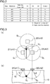
- the sum of the values of internal resistance (R b1 + R b2 ) is considered to be proportional to the sum (D 1 + D 2 ) of a distance D 1 from the electrode 21 to the signal source Vs and a distance D 2 from the electrode 22 to the signal source Vs, as illustrated in the portion (b) of FIG. 7 . Accordingly, from the eq. (12), (13), and (14), the sums of distances (D 1 + D 2 ), (D 2 + D 3 ), (D 3 + D 1 ) between each electrode and the signal source Vs are given by eqs. (15), (16), and (17), respectively. [Eq.
- ⁇ represents a constant defined, for example, by the conductivity of the living body 10.
- the signal source Vs is considered to exist at a point of intersection of an ellipse E 1 having focal points at the electrodes 21 and 22 (the channels ch 1 and ch 2 ), an ellipse E 2 having focal points at the electrodes 22 and 23 (the channels ch 2 and ch 3 ), and an ellipse E 3 having focal points at the electrodes 23 and 21 (the channels ch 3 and ch 1 ).
- the three-dimensional position coordinates (x, y, z) of the signal source Vs may be determined by solving eqs. (18), (19), and (20) of the ellipses E 1 , E 2 , and E 3 .
- the position coordinates of the electrodes 21, 22, and 23 are denoted by (a 1 , b 1 , c 1 ), (a 2 , b 2 , c 2 ), (a 3 , b 3 , c 3 ), respectively.
- x ⁇ a 1 2 + y ⁇ b 1 2 + z ⁇ c 1 2 + x ⁇ a 2 2 + y ⁇ b 2 2 + z ⁇ c 2 2 D 1 + D 2 [Eq.
- the constant ⁇ may be estimated and determined, in advance, based on a radioscopic image of the living body 10, showing the signal source Vs.
- the eqs. (18), (19), and (20) of this embodiment do not contain the value R b0 of internal resistance between the signal source Vs and the ground electrode 20. Thus, the three-dimensional position of the signal source Vs may be detected more accurately.
- FIG. 5 also illustrates a configuration of a device for detecting a position of a signal source in a living body, according to this embodiment of the present invention.
- the device for detecting a position of a signal source in a living body includes at least three electrodes 21, 22, and 23 arranged on a surface of a living body 10, and a switching means SW switching to alternately connect a first external resistance and a second external resistance in parallel between the electrodes 21, 22, and 23.
- the device further includes a differential amplifier (a measurer) 30 and a group of switches S 1 , S 2 , S 3 , SS 1 , SS 2 , and SS 3 .
- the detector may be configured as, for example, a CPU which computes measurement data from the differential amplifier 30.
- the portions (a)-(c) of FIG. 8 are a network diagram describing a method for detecting a position of a signal source in a living body, according to a third example not falling within the scope of the claims.
- the method for detecting a position of a signal source in a living body is an embodiment of the first embodiment.
- the electrode 21 (the channel ch 1 ) is connected to the ground potential.
- the electrode 22 (the channel ch 2 ) is connected to the ground potential.
- the electrode 23 (the channel ch 3 ) is connected to the ground potential.
- the living body is regarded as a network comprised of a signal source and a large number of resistances.
- the resistance values between the signal source Vs and the electrodes 21, 22, and 23 and between the signal source Vs and the ground electrode are obtained as values of combined resistance of a network between the signal source Vs and the electrodes and values of combined resistance of a network between the signal source Vs and the ground electrode. Therefore, a different combination of an electrode connected to the ground potential and an electrode subjected to the voltage measurement results in a different network from the signal source Vs to the electrodes, and different resistance values are determined even at the same electrode. Specifically, in the portions (a)-(c) of FIG.
- R b1 and R' b1 each represent a resistance value from the signal source Vs to the electrodes 21, R b2 , and R' b2 , each represent a resistance value from the signal source Vs to the electrodes 22, and R b3 , and R' b3 each represent a resistance value from the signal source Vs to the electrodes 23.
- a ratio (attenuation ratio) V' 12 /V 12 between the first voltage V 12 and the second voltage V' 12 that are generated between the electrode 21 (ground potential) and the electrode 22 (i.e., between the channels ch 1 and ch 2 ) is given by eq. (21).
- the first voltage V 12 and the second voltage V' 12 are generated between the electrodes 21 and 22 respectively when no external resistance is connected between the electrodes 21 and 22 and when external resistance Rg is connected between the electrodes 21 and 22.
- V ′ 12 V 12 R g R b 1 + R b 2 + R g
- a ratio (attenuation ratio) V' 23 /V 23 between the first voltage V 23 and the second voltage V' 23 that are generated between the electrode 22 (ground potential) and the electrode 23 (i.e., between the channels ch 2 and ch 3 ) is given by eq. (22).
- a ratio (attenuation ratio) V' 31 /V 31 between the first voltage V 31 and the second voltage V' 31 that are generated between the electrode 23 (ground potential) and the electrode 21 (i.e., between the channels ch 3 and ch 1 ) is given by eq. (23).
- V ′ 23 V 23 R g R b 2 + R b 3 + R g
- V ′ 31 V 31 R g R b 3 + R b 1 + R g
- the eqs. (21), (22), and (23) are the same as the eqs. (12), (13), and (14) described in the second embodiment.
- the sums of the distances (D 1 + D 2 ), (D 2 + D 3 ), and (D 3 + D 1 ) between the electrodes 21, 22, and 23 and the signal source Vs are expressed by the above-described eqs. (15), (16), and (17). Therefore, the three-dimensional position coordinates (x, y, z) of the signal source Vs may be determined by solving the eqs. (18), (19), and (20) of the three ellipses E 1 , E 2 , and E 3 above described.
- the ellipse E 1 has the focal points at the electrodes 21 and 22 (the channels ch 1 and ch 2 ), the ellipse E 2 has the focal points at the electrodes 22 and 23 (the channels ch 2 and ch 3 ), and the ellipse E 3 has the focal points at the electrodes 23 and 21 (the channels ch 3 and ch 1 ).
- the ground electrode does not have to be arranged on the surface of the living body 10.
- this embodiment has a simpler configuration and enables accurate detection of the three-dimensional position of the signal source Vs in the living body.
- the three-dimensional position coordinates (x, y, z) of the signal source Vs are determined by solving the eqs. (9), (10), and (11) of the three spheres Q 1 , Q 2 , and Q 3 .
- the value R b0 of internal resistance between the signal source Vs and the ground electrode 20 is defined as an unknown
- the three-dimensional position coordinates (x, y, z) of the signal source Vs are determined by solving the eqs. (18), (19), and (20) of the three ellipses E 1 , E 2 , and E 3 described in the second embodiment.
- the ellipse E 1 has the focal points at the electrode 21 (the channel ch 1 ) and the ground electrode 20
- the ellipse E 2 has the focal points at the electrode 22 (the channel ch 2 ) and the ground electrode 20
- ellipse E 3 has the focal points at the electrode 23 (the channel ch 3 ) and the ground electrode 20.
- the three-dimensional position coordinates (x, y, z) of the signal source Vs are determined by solving the eqs. (18), (19), and (20) of the three ellipses E 1 , E 2 , and E 3 .
- the eqs. (18), (19), and (20) may be changed to equations respectively expressing the three unknowns R b1 , R b2 , and R b3 , and the three-dimensional position coordinates may be determined by solving the equations of the three spheres.
- the three electrodes 21, 22, and 23 are arranged on the surface of the living body 10. However, to detect the position of the signal source Vs with higher accuracy, more than three electrodes may be arranged. Further, although one ground electrode was arranged in the embodiments described above, two or more ground electrodes may be arranged.
- the first external resistance and the second external resistance are connected in parallel between the electrodes 21, 22, and 23 and the ground electrode 20, and the switching means SW alternately switches the first and second external resistances.
- the switching means SW does not necessarily has to be used.
- the electrodes 21, 22, and 23 are comprised of adjacent electrodes 21a and 21b, adjacent electrodes 22a and 22b, and adjacent electrodes 23a and 23b, respectively.
- a first external resistance Rg1 may be connected to one of the adjacent electrodes of each electrode, namely the electrodes 21a, 22a, or 23a to form a circuit.
- a second external resistance Rg2 may be connected to the other one of the adjacent electrodes of each electrode, namely the electrodes 21b, 22b, or 23b to form another circuit. In this manner, first and second voltages generated at each of the electrodes 21, 22, and 23 may be measured, thereby detecting the position of the signal source Vs in the living body.
- FIG. 9 illustrates an exemplary network in which the switching means SW is not used.
- a signal source Vs, internal resistances R b1 , R b2 , R b3 , and R b0 between the signal source Vs and the electrode 21 (21a, 21b), the electrode 22 (22a, 22b), the electrode 23 (23a, 23b), and the ground electrode 20 are omitted from FIG. 9 .
- the first external resistance Rg1 and the second external resistance Rg2 are each connected in parallel between the three electrodes 21 (21a, 21b), 22 (22a, 22b), 23 (23a, 23b) and the ground electrode 20 that are arranged on a surface of the living body 10.
- a first voltage V 1 which is generated when the first external resistance Rg1 is connected in parallel between the electrode 21a and the ground electrode 20 is amplified and measured by an amplifier 30A 1 .
- a second voltage V' 1 generated when the second external resistance Rg2 is connected in parallel between the electrode 21b and the ground electrode 20 is amplified and measured by an amplifier 30B 1 .
- a first voltage V 2 which is generated when the first external resistance Rg1 is connected in parallel between the electrode 22a and the ground electrode 20 is amplified and measured by an amplifier 30A 2 .
- a second voltage V' 2 which is generated when the second external resistance Rg2 is connected in parallel between the electrode 22b and the ground electrode 20 is amplified and measured by an amplifier 30B 2 .
- a first voltage V 3 which is generated when the first external resistance Rg1 is connected in parallel between the electrode 23a and the ground electrode 20 is amplified and measured by an amplifier 30A 3 .
- a second voltage V' 3 which is generated when the second external resistance Rg2 is connected in parallel between the electrode 23b and the ground electrode 20 is amplified and measured by an amplifier 30B 3 .
Landscapes
- Health & Medical Sciences (AREA)
- Life Sciences & Earth Sciences (AREA)
- Medical Informatics (AREA)
- Biophysics (AREA)
- Pathology (AREA)
- Engineering & Computer Science (AREA)
- Biomedical Technology (AREA)
- Heart & Thoracic Surgery (AREA)
- Physics & Mathematics (AREA)
- Molecular Biology (AREA)
- Surgery (AREA)
- Animal Behavior & Ethology (AREA)
- General Health & Medical Sciences (AREA)
- Public Health (AREA)
- Veterinary Medicine (AREA)
- Cardiology (AREA)
- Measurement And Recording Of Electrical Phenomena And Electrical Characteristics Of The Living Body (AREA)
Claims (4)
- Verfahren zum Erfassen einer Position einer Signalquelle in einem lebenden Körper, basierend auf Spannungen, die an Elektroden erzeugt werden, die auf einer Oberfläche des lebenden Körpers angeordnet sind, wobei das Verfahren umfasst:Anordnen der Elektroden, die eine erste Elektrode, eine zweite Elektrode und eine dritte Elektrode beinhalten, auf der Oberfläche des lebenden Körpers;abwechselnd Verbinden eines ersten Außenwiderstands und eines zweiten Außenwiderstands zwischen der ersten und zweiten Elektrode, zwischen der zweiten und dritten Elektrode und zwischen der dritten und ersten Elektrode;Messen der ersten Spannungen V12, V23 und V31, die zwischen den jeweiligen Elektroden erzeugt werden, wenn der erste Außenwiderstand zwischen den jeweiligen Elektroden verbunden ist, und der zweiten Spannungen V'12, V'23 und V'31, die zwischen den jeweiligen Elektroden erzeugt werden, wenn der zweite Außenwiderstand zwischen den jeweiligen Elektroden geschaltet ist; undBerechnen von drei Verhältnissen V12/V'12, V21/V'21 und V31/V'31 jeweils aus den ersten Spannungen V12, V23, V31 und den zweiten Spannungen V'12, V'23 und V'31 und Erfassen der Position der Signalquelle im lebenden Körper basierend auf den drei Verhältnissen V12/V'12, V21/V'21 und V31/V'31 und den Positionskoordinaten der ersten, zweiten und dritten Elektrode auf der Oberfläche des lebenden Körpers und unter der Annahme, dass die Leitfähigkeit im lebenden Körper einheitlich ist.
- Verfahren nach Anspruch 1, wobei
einer von dem ersten Außenwiderstand oder dem zweiten Außenwiderstand einen unendlichen Widerstandswert aufweist,
der andere von dem ersten Außenwiderstand oder dem zweiten Außenwiderstand einen Widerstandswert von Rg aufweist, und
die Position (x, y, z) der Signalquelle im lebenden Körper durch Lösen der drei nachfolgend beschriebenen Gleichungen (A), (B) und (C) erfasst wird:


- Verfahren nach Anspruch 1 oder 2, wobei
Messungen der ersten und zweiten Spannung als ein Zyklus wiederholt werden, um Zeitreihen-Messdaten der Spannungsverhältnisse durch Wiederholung des Zyklus aufzunehmen, und
eine Bewegungsbahn der Position der Signalquelle im lebenden Körper basierend auf den aufgenommenen Zeitreihen-Messdaten erfasst wird. - Vorrichtung zum Erfassen einer Position einer Signalquelle in einem lebenden Körper, basierend auf Spannungen, die an Elektroden erzeugt werden, die auf einer Oberfläche des lebenden Körpers angeordnet sind, wobei die Vorrichtung umfasst:die Elektroden, die eine erste Elektrode, eine zweite Elektrode und eine dritte Elektrode beinhalten, die auf der Oberfläche des lebenden Körpers anordenbar sind;einen Verbinder, der abwechselnd einen ersten Außenwiderstand und einen zweiten Außenwiderstand zwischen der ersten und zweiten Elektrode, zwischen der zweiten und dritten Elektrode und zwischen der dritten und ersten Elektrode verbindet;ein Messgerät, das in einem Zustand, in dem die Elektroden auf der Oberfläche des lebenden Körpers angeordnet sind, erste Spannungen V12, V23 und V31, die zwischen den jeweiligen Elektroden erzeugt werden, wenn der Verbinder den ersten Außenwiderstand zwischen den jeweiligen Elektroden verbindet, und zweite Spannungen V'12, V'23 und V'31, die zwischen den jeweiligen Elektroden erzeugt werden, wenn die Verbinder den zweiten Außenwiderstand zwischen den jeweiligen Elektroden verbinden, misst; undeinen Detektor, der drei Verhältnisse V12/V'12, V21/V'21 bzw. V31/V'31 aus den ersten Spannungen V12, V23, V31 und den zweiten Spannungen V'12, V'23 und V'31 berechnet und die Position der Signalquelle im lebenden Körper basierend auf den drei Verhältnissen V12/V'12, V21/V'21 und V31/V'31 und den Positionskoordinaten der Elektroden der ersten, zweiten und dritten Elektrode auf der Oberfläche des lebenden Körpers erfasst und unter der Annahme, dass die Leitfähigkeit innerhalb des lebenden Körpers einheitlich ist.
Applications Claiming Priority (1)
| Application Number | Priority Date | Filing Date | Title |
|---|---|---|---|
| PCT/JP2014/005732 WO2016075726A1 (ja) | 2014-11-14 | 2014-11-14 | 生体内信号源位置検出方法及び生体内信号源位置検出装置 |
Publications (3)
| Publication Number | Publication Date |
|---|---|
| EP3202319A1 EP3202319A1 (de) | 2017-08-09 |
| EP3202319A4 EP3202319A4 (de) | 2017-10-18 |
| EP3202319B1 true EP3202319B1 (de) | 2019-04-24 |
Family
ID=55953839
Family Applications (1)
| Application Number | Title | Priority Date | Filing Date |
|---|---|---|---|
| EP14906139.2A Not-in-force EP3202319B1 (de) | 2014-11-14 | 2014-11-14 | Verfahren zur erkennung der position einer signalquelle in einem lebenden körper und vorrichtung zur erkennung der position einer signalquelle in einem lebenden körper |
Country Status (5)
| Country | Link |
|---|---|
| US (1) | US10165958B2 (de) |
| EP (1) | EP3202319B1 (de) |
| JP (1) | JP6492103B2 (de) |
| CN (1) | CN106999086B (de) |
| WO (1) | WO2016075726A1 (de) |
Families Citing this family (4)
| Publication number | Priority date | Publication date | Assignee | Title |
|---|---|---|---|---|
| JP6770266B2 (ja) * | 2016-08-18 | 2020-10-14 | 東レエンジニアリング株式会社 | 生体内信号源検出方法及び生体内信号源検出装置 |
| JP6991498B2 (ja) * | 2017-03-13 | 2022-01-12 | 東レエンジニアリング株式会社 | 生体内信号強度検出装置 |
| JP7117727B2 (ja) * | 2018-03-19 | 2022-08-15 | 東レエンジニアリング株式会社 | 生体内信号源位置検出方法 |
| EP3943003A4 (de) * | 2019-03-19 | 2022-06-22 | Toray Engineering Co., Ltd. | Verfahren und system zur bewertung der muskelermüdung |
Family Cites Families (6)
| Publication number | Priority date | Publication date | Assignee | Title |
|---|---|---|---|---|
| JP3226351B2 (ja) * | 1992-10-15 | 2001-11-05 | 中央電子株式会社 | 信号源の推定方法 |
| JP3771696B2 (ja) | 1997-10-09 | 2006-04-26 | 阿波エンジニアリング株式会社 | 体表面心電計と体表面電位分布図の表示方法 |
| US20020045836A1 (en) * | 2000-10-16 | 2002-04-18 | Dima Alkawwas | Operation of wireless biopotential monitoring system |
| US6780182B2 (en) * | 2002-05-23 | 2004-08-24 | Adiana, Inc. | Catheter placement detection system and operator interface |
| JP2007268034A (ja) * | 2006-03-31 | 2007-10-18 | Ritsumeikan | 生体信号計測方法及び装置 |
| JP5178909B2 (ja) * | 2009-02-24 | 2013-04-10 | 学校法人立命館 | インピーダンス切替型多点表面電極を用いた生体内電位の推定装置及びその方法 |
-
2014
- 2014-11-14 JP JP2016558446A patent/JP6492103B2/ja not_active Expired - Fee Related
- 2014-11-14 WO PCT/JP2014/005732 patent/WO2016075726A1/ja not_active Ceased
- 2014-11-14 CN CN201480083283.9A patent/CN106999086B/zh not_active Expired - Fee Related
- 2014-11-14 EP EP14906139.2A patent/EP3202319B1/de not_active Not-in-force
- 2014-11-14 US US15/524,892 patent/US10165958B2/en active Active
Non-Patent Citations (1)
| Title |
|---|
| None * |
Also Published As
| Publication number | Publication date |
|---|---|
| US10165958B2 (en) | 2019-01-01 |
| US20170354340A1 (en) | 2017-12-14 |
| CN106999086A (zh) | 2017-08-01 |
| JP6492103B2 (ja) | 2019-03-27 |
| EP3202319A4 (de) | 2017-10-18 |
| WO2016075726A1 (ja) | 2016-05-19 |
| CN106999086B (zh) | 2020-06-23 |
| EP3202319A1 (de) | 2017-08-09 |
| JPWO2016075726A1 (ja) | 2017-08-31 |
Similar Documents
| Publication | Publication Date | Title |
|---|---|---|
| CN112741611B (zh) | 基于毫米波感知的多人体生命体征同步监测系统及方法 | |
| US9149235B2 (en) | Oedema detection | |
| US8831898B2 (en) | Impedance measurement circuit and method | |
| US20190328258A1 (en) | Small-scale time delay and single-shot conduction velocity analysis and mapping for cardiac electrophysiology | |
| EP3209197B1 (de) | Verfahren und vorrichtung zur simultanen impedanzprüfung | |
| US20130338529A1 (en) | Bioelectric signal measurement apparatus | |
| EP3202319A1 (de) | Verfahren zur erkennung der position einer signalquelle in einem lebenden körper und vorrichtung zur erkennung der position einer signalquelle in einem lebenden körper | |
| US5694942A (en) | Analysis of heart waveforms | |
| KR101908786B1 (ko) | 데이터 유사도 평가 시스템 | |
| US10506942B2 (en) | In-vivo signal source detection method and in-vivo signal source detection device | |
| CN104346399A (zh) | 基于pk-pd的中药复方物质基础数据分析方法 | |
| JP6518084B2 (ja) | 生体内信号源位置検出装置及び生体内信号源位置検出方法 | |
| KR20170037704A (ko) | 흉부임피던스를 측정을 위한 다중 전극 및 이를 이용한 흉부 임피던스 측정방법 | |
| KR20170008516A (ko) | 맥파 전달 시간을 이용한 수축기 혈압 산출 장치 및 그 방법 | |
| JP6588614B2 (ja) | 生体内信号源位置検出方法及び生体内信号源位置検出装置 | |
| Holobar et al. | A signal-based approach for assessing the accuracy of high-density surface EMG decomposition | |
| US20040254436A1 (en) | Automatic continuous measuring device for ventricle volume | |
| JP3909710B2 (ja) | 心室容積測定装置及び心室容積測定方法 | |
| DE102008032980A1 (de) | Sonde und Vorrichtung für die Messung dielektrischer Materialeigenschaften | |
| JP7117727B2 (ja) | 生体内信号源位置検出方法 | |
| US20160113547A1 (en) | Device for detecting electric potentials | |
| Sundar et al. | Conduction velocity distribution estimation using the collision technique—Theory and simulation study | |
| RU148056U1 (ru) | Реограф | |
| KR20240174452A (ko) | Pwm을 활용한 임피던스 모니터링 장치 및 방법 | |
| RU2577178C2 (ru) | Способ измерения сопротивления участка тела человека |
Legal Events
| Date | Code | Title | Description |
|---|---|---|---|
| STAA | Information on the status of an ep patent application or granted ep patent |
Free format text: STATUS: THE INTERNATIONAL PUBLICATION HAS BEEN MADE |
|
| PUAI | Public reference made under article 153(3) epc to a published international application that has entered the european phase |
Free format text: ORIGINAL CODE: 0009012 |
|
| STAA | Information on the status of an ep patent application or granted ep patent |
Free format text: STATUS: REQUEST FOR EXAMINATION WAS MADE |
|
| 17P | Request for examination filed |
Effective date: 20170504 |
|
| AK | Designated contracting states |
Kind code of ref document: A1 Designated state(s): AL AT BE BG CH CY CZ DE DK EE ES FI FR GB GR HR HU IE IS IT LI LT LU LV MC MK MT NL NO PL PT RO RS SE SI SK SM TR |
|
| AX | Request for extension of the european patent |
Extension state: BA ME |
|
| A4 | Supplementary search report drawn up and despatched |
Effective date: 20170918 |
|
| RIC1 | Information provided on ipc code assigned before grant |
Ipc: A61B 5/0428 20060101AFI20170912BHEP Ipc: A61B 5/0408 20060101ALI20170912BHEP |
|
| DAX | Request for extension of the european patent (deleted) | ||
| STAA | Information on the status of an ep patent application or granted ep patent |
Free format text: STATUS: EXAMINATION IS IN PROGRESS |
|
| 17Q | First examination report despatched |
Effective date: 20180713 |
|
| GRAP | Despatch of communication of intention to grant a patent |
Free format text: ORIGINAL CODE: EPIDOSNIGR1 |
|
| STAA | Information on the status of an ep patent application or granted ep patent |
Free format text: STATUS: GRANT OF PATENT IS INTENDED |
|
| INTG | Intention to grant announced |
Effective date: 20190104 |
|
| GRAS | Grant fee paid |
Free format text: ORIGINAL CODE: EPIDOSNIGR3 |
|
| GRAA | (expected) grant |
Free format text: ORIGINAL CODE: 0009210 |
|
| STAA | Information on the status of an ep patent application or granted ep patent |
Free format text: STATUS: THE PATENT HAS BEEN GRANTED |
|
| AK | Designated contracting states |
Kind code of ref document: B1 Designated state(s): AL AT BE BG CH CY CZ DE DK EE ES FI FR GB GR HR HU IE IS IT LI LT LU LV MC MK MT NL NO PL PT RO RS SE SI SK SM TR |
|
| REG | Reference to a national code |
Ref country code: GB Ref legal event code: FG4D |
|
| REG | Reference to a national code |
Ref country code: CH Ref legal event code: EP |
|
| REG | Reference to a national code |
Ref country code: AT Ref legal event code: REF Ref document number: 1123142 Country of ref document: AT Kind code of ref document: T Effective date: 20190515 Ref country code: IE Ref legal event code: FG4D |
|
| REG | Reference to a national code |
Ref country code: DE Ref legal event code: R096 Ref document number: 602014045572 Country of ref document: DE |
|
| REG | Reference to a national code |
Ref country code: NL Ref legal event code: MP Effective date: 20190424 |
|
| REG | Reference to a national code |
Ref country code: LT Ref legal event code: MG4D |
|
| PG25 | Lapsed in a contracting state [announced via postgrant information from national office to epo] |
Ref country code: NL Free format text: LAPSE BECAUSE OF FAILURE TO SUBMIT A TRANSLATION OF THE DESCRIPTION OR TO PAY THE FEE WITHIN THE PRESCRIBED TIME-LIMIT Effective date: 20190424 |
|
| PG25 | Lapsed in a contracting state [announced via postgrant information from national office to epo] |
Ref country code: ES Free format text: LAPSE BECAUSE OF FAILURE TO SUBMIT A TRANSLATION OF THE DESCRIPTION OR TO PAY THE FEE WITHIN THE PRESCRIBED TIME-LIMIT Effective date: 20190424 Ref country code: AL Free format text: LAPSE BECAUSE OF FAILURE TO SUBMIT A TRANSLATION OF THE DESCRIPTION OR TO PAY THE FEE WITHIN THE PRESCRIBED TIME-LIMIT Effective date: 20190424 Ref country code: PT Free format text: LAPSE BECAUSE OF FAILURE TO SUBMIT A TRANSLATION OF THE DESCRIPTION OR TO PAY THE FEE WITHIN THE PRESCRIBED TIME-LIMIT Effective date: 20190824 Ref country code: SE Free format text: LAPSE BECAUSE OF FAILURE TO SUBMIT A TRANSLATION OF THE DESCRIPTION OR TO PAY THE FEE WITHIN THE PRESCRIBED TIME-LIMIT Effective date: 20190424 Ref country code: FI Free format text: LAPSE BECAUSE OF FAILURE TO SUBMIT A TRANSLATION OF THE DESCRIPTION OR TO PAY THE FEE WITHIN THE PRESCRIBED TIME-LIMIT Effective date: 20190424 Ref country code: NO Free format text: LAPSE BECAUSE OF FAILURE TO SUBMIT A TRANSLATION OF THE DESCRIPTION OR TO PAY THE FEE WITHIN THE PRESCRIBED TIME-LIMIT Effective date: 20190724 Ref country code: HR Free format text: LAPSE BECAUSE OF FAILURE TO SUBMIT A TRANSLATION OF THE DESCRIPTION OR TO PAY THE FEE WITHIN THE PRESCRIBED TIME-LIMIT Effective date: 20190424 Ref country code: LT Free format text: LAPSE BECAUSE OF FAILURE TO SUBMIT A TRANSLATION OF THE DESCRIPTION OR TO PAY THE FEE WITHIN THE PRESCRIBED TIME-LIMIT Effective date: 20190424 |
|
| PG25 | Lapsed in a contracting state [announced via postgrant information from national office to epo] |
Ref country code: RS Free format text: LAPSE BECAUSE OF FAILURE TO SUBMIT A TRANSLATION OF THE DESCRIPTION OR TO PAY THE FEE WITHIN THE PRESCRIBED TIME-LIMIT Effective date: 20190424 Ref country code: GR Free format text: LAPSE BECAUSE OF FAILURE TO SUBMIT A TRANSLATION OF THE DESCRIPTION OR TO PAY THE FEE WITHIN THE PRESCRIBED TIME-LIMIT Effective date: 20190725 Ref country code: PL Free format text: LAPSE BECAUSE OF FAILURE TO SUBMIT A TRANSLATION OF THE DESCRIPTION OR TO PAY THE FEE WITHIN THE PRESCRIBED TIME-LIMIT Effective date: 20190424 Ref country code: LV Free format text: LAPSE BECAUSE OF FAILURE TO SUBMIT A TRANSLATION OF THE DESCRIPTION OR TO PAY THE FEE WITHIN THE PRESCRIBED TIME-LIMIT Effective date: 20190424 Ref country code: BG Free format text: LAPSE BECAUSE OF FAILURE TO SUBMIT A TRANSLATION OF THE DESCRIPTION OR TO PAY THE FEE WITHIN THE PRESCRIBED TIME-LIMIT Effective date: 20190724 |
|
| REG | Reference to a national code |
Ref country code: AT Ref legal event code: MK05 Ref document number: 1123142 Country of ref document: AT Kind code of ref document: T Effective date: 20190424 |
|
| PG25 | Lapsed in a contracting state [announced via postgrant information from national office to epo] |
Ref country code: IS Free format text: LAPSE BECAUSE OF FAILURE TO SUBMIT A TRANSLATION OF THE DESCRIPTION OR TO PAY THE FEE WITHIN THE PRESCRIBED TIME-LIMIT Effective date: 20190824 |
|
| REG | Reference to a national code |
Ref country code: DE Ref legal event code: R097 Ref document number: 602014045572 Country of ref document: DE |
|
| PG25 | Lapsed in a contracting state [announced via postgrant information from national office to epo] |
Ref country code: AT Free format text: LAPSE BECAUSE OF FAILURE TO SUBMIT A TRANSLATION OF THE DESCRIPTION OR TO PAY THE FEE WITHIN THE PRESCRIBED TIME-LIMIT Effective date: 20190424 Ref country code: DK Free format text: LAPSE BECAUSE OF FAILURE TO SUBMIT A TRANSLATION OF THE DESCRIPTION OR TO PAY THE FEE WITHIN THE PRESCRIBED TIME-LIMIT Effective date: 20190424 Ref country code: EE Free format text: LAPSE BECAUSE OF FAILURE TO SUBMIT A TRANSLATION OF THE DESCRIPTION OR TO PAY THE FEE WITHIN THE PRESCRIBED TIME-LIMIT Effective date: 20190424 Ref country code: RO Free format text: LAPSE BECAUSE OF FAILURE TO SUBMIT A TRANSLATION OF THE DESCRIPTION OR TO PAY THE FEE WITHIN THE PRESCRIBED TIME-LIMIT Effective date: 20190424 Ref country code: CZ Free format text: LAPSE BECAUSE OF FAILURE TO SUBMIT A TRANSLATION OF THE DESCRIPTION OR TO PAY THE FEE WITHIN THE PRESCRIBED TIME-LIMIT Effective date: 20190424 Ref country code: SK Free format text: LAPSE BECAUSE OF FAILURE TO SUBMIT A TRANSLATION OF THE DESCRIPTION OR TO PAY THE FEE WITHIN THE PRESCRIBED TIME-LIMIT Effective date: 20190424 |
|
| PG25 | Lapsed in a contracting state [announced via postgrant information from national office to epo] |
Ref country code: SM Free format text: LAPSE BECAUSE OF FAILURE TO SUBMIT A TRANSLATION OF THE DESCRIPTION OR TO PAY THE FEE WITHIN THE PRESCRIBED TIME-LIMIT Effective date: 20190424 Ref country code: IT Free format text: LAPSE BECAUSE OF FAILURE TO SUBMIT A TRANSLATION OF THE DESCRIPTION OR TO PAY THE FEE WITHIN THE PRESCRIBED TIME-LIMIT Effective date: 20190424 |
|
| PLBE | No opposition filed within time limit |
Free format text: ORIGINAL CODE: 0009261 |
|
| STAA | Information on the status of an ep patent application or granted ep patent |
Free format text: STATUS: NO OPPOSITION FILED WITHIN TIME LIMIT |
|
| PG25 | Lapsed in a contracting state [announced via postgrant information from national office to epo] |
Ref country code: TR Free format text: LAPSE BECAUSE OF FAILURE TO SUBMIT A TRANSLATION OF THE DESCRIPTION OR TO PAY THE FEE WITHIN THE PRESCRIBED TIME-LIMIT Effective date: 20190424 |
|
| 26N | No opposition filed |
Effective date: 20200127 |
|
| PG25 | Lapsed in a contracting state [announced via postgrant information from national office to epo] |
Ref country code: SI Free format text: LAPSE BECAUSE OF FAILURE TO SUBMIT A TRANSLATION OF THE DESCRIPTION OR TO PAY THE FEE WITHIN THE PRESCRIBED TIME-LIMIT Effective date: 20190424 |
|
| REG | Reference to a national code |
Ref country code: CH Ref legal event code: PL |
|
| PG25 | Lapsed in a contracting state [announced via postgrant information from national office to epo] |
Ref country code: CH Free format text: LAPSE BECAUSE OF NON-PAYMENT OF DUE FEES Effective date: 20191130 Ref country code: LI Free format text: LAPSE BECAUSE OF NON-PAYMENT OF DUE FEES Effective date: 20191130 Ref country code: LU Free format text: LAPSE BECAUSE OF NON-PAYMENT OF DUE FEES Effective date: 20191114 Ref country code: MC Free format text: LAPSE BECAUSE OF FAILURE TO SUBMIT A TRANSLATION OF THE DESCRIPTION OR TO PAY THE FEE WITHIN THE PRESCRIBED TIME-LIMIT Effective date: 20190424 |
|
| REG | Reference to a national code |
Ref country code: BE Ref legal event code: MM Effective date: 20191130 |
|
| PG25 | Lapsed in a contracting state [announced via postgrant information from national office to epo] |
Ref country code: IE Free format text: LAPSE BECAUSE OF NON-PAYMENT OF DUE FEES Effective date: 20191114 |
|
| REG | Reference to a national code |
Ref country code: DE Ref legal event code: R079 Ref document number: 602014045572 Country of ref document: DE Free format text: PREVIOUS MAIN CLASS: A61B0005042800 Ipc: A61B0005308000 |
|
| PG25 | Lapsed in a contracting state [announced via postgrant information from national office to epo] |
Ref country code: BE Free format text: LAPSE BECAUSE OF NON-PAYMENT OF DUE FEES Effective date: 20191130 |
|
| PG25 | Lapsed in a contracting state [announced via postgrant information from national office to epo] |
Ref country code: CY Free format text: LAPSE BECAUSE OF FAILURE TO SUBMIT A TRANSLATION OF THE DESCRIPTION OR TO PAY THE FEE WITHIN THE PRESCRIBED TIME-LIMIT Effective date: 20190424 |
|
| PG25 | Lapsed in a contracting state [announced via postgrant information from national office to epo] |
Ref country code: HU Free format text: LAPSE BECAUSE OF FAILURE TO SUBMIT A TRANSLATION OF THE DESCRIPTION OR TO PAY THE FEE WITHIN THE PRESCRIBED TIME-LIMIT; INVALID AB INITIO Effective date: 20141114 Ref country code: MT Free format text: LAPSE BECAUSE OF FAILURE TO SUBMIT A TRANSLATION OF THE DESCRIPTION OR TO PAY THE FEE WITHIN THE PRESCRIBED TIME-LIMIT Effective date: 20190424 |
|
| PG25 | Lapsed in a contracting state [announced via postgrant information from national office to epo] |
Ref country code: MK Free format text: LAPSE BECAUSE OF FAILURE TO SUBMIT A TRANSLATION OF THE DESCRIPTION OR TO PAY THE FEE WITHIN THE PRESCRIBED TIME-LIMIT Effective date: 20190424 |
|
| PGFP | Annual fee paid to national office [announced via postgrant information from national office to epo] |
Ref country code: GB Payment date: 20221125 Year of fee payment: 9 Ref country code: FR Payment date: 20221129 Year of fee payment: 9 Ref country code: DE Payment date: 20221123 Year of fee payment: 9 |
|
| REG | Reference to a national code |
Ref country code: DE Ref legal event code: R119 Ref document number: 602014045572 Country of ref document: DE |
|
| GBPC | Gb: european patent ceased through non-payment of renewal fee |
Effective date: 20231114 |
|
| PG25 | Lapsed in a contracting state [announced via postgrant information from national office to epo] |
Ref country code: DE Free format text: LAPSE BECAUSE OF NON-PAYMENT OF DUE FEES Effective date: 20240601 |
|
| PG25 | Lapsed in a contracting state [announced via postgrant information from national office to epo] |
Ref country code: GB Free format text: LAPSE BECAUSE OF NON-PAYMENT OF DUE FEES Effective date: 20231114 |
|
| PG25 | Lapsed in a contracting state [announced via postgrant information from national office to epo] |
Ref country code: FR Free format text: LAPSE BECAUSE OF NON-PAYMENT OF DUE FEES Effective date: 20231130 |
|
| PG25 | Lapsed in a contracting state [announced via postgrant information from national office to epo] |
Ref country code: GB Free format text: LAPSE BECAUSE OF NON-PAYMENT OF DUE FEES Effective date: 20231114 Ref country code: FR Free format text: LAPSE BECAUSE OF NON-PAYMENT OF DUE FEES Effective date: 20231130 Ref country code: DE Free format text: LAPSE BECAUSE OF NON-PAYMENT OF DUE FEES Effective date: 20240601 |