EP3202015B1 - Verbesserte vorrichtung zur leistungsübertragungsverwaltung - Google Patents
Verbesserte vorrichtung zur leistungsübertragungsverwaltung Download PDFInfo
- Publication number
- EP3202015B1 EP3202015B1 EP15791683.4A EP15791683A EP3202015B1 EP 3202015 B1 EP3202015 B1 EP 3202015B1 EP 15791683 A EP15791683 A EP 15791683A EP 3202015 B1 EP3202015 B1 EP 3202015B1
- Authority
- EP
- European Patent Office
- Prior art keywords
- terminal
- diode
- switch
- current
- voltage
- Prior art date
- Legal status (The legal status is an assumption and is not a legal conclusion. Google has not performed a legal analysis and makes no representation as to the accuracy of the status listed.)
- Active
Links
Images


Classifications
-
- H—ELECTRICITY
- H02—GENERATION; CONVERSION OR DISTRIBUTION OF ELECTRIC POWER
- H02J—ELECTRIC POWER NETWORKS; CIRCUIT ARRANGEMENTS OR SYSTEMS FOR SUPPLYING OR DISTRIBUTING ELECTRIC POWER; SYSTEMS FOR STORING ELECTRIC ENERGY
- H02J7/00—Circuit arrangements for charging or discharging batteries or for supplying loads from batteries
- H02J7/14—Circuit arrangements for charging or discharging batteries or for supplying loads from batteries for charging batteries from dynamo-electric generators driven at varying speed, e.g. on vehicle
- H02J7/1423—Circuit arrangements for charging or discharging batteries or for supplying loads from batteries for charging batteries from dynamo-electric generators driven at varying speed, e.g. on vehicle with multiple batteries
-
- B—PERFORMING OPERATIONS; TRANSPORTING
- B60—VEHICLES IN GENERAL
- B60R—VEHICLES, VEHICLE FITTINGS, OR VEHICLE PARTS, NOT OTHERWISE PROVIDED FOR
- B60R16/00—Electric or fluid circuits specially adapted for vehicles and not otherwise provided for; Arrangement of elements of electric or fluid circuits specially adapted for vehicles and not otherwise provided for
- B60R16/02—Electric or fluid circuits specially adapted for vehicles and not otherwise provided for; Arrangement of elements of electric or fluid circuits specially adapted for vehicles and not otherwise provided for electric constitutive elements
- B60R16/03—Electric or fluid circuits specially adapted for vehicles and not otherwise provided for; Arrangement of elements of electric or fluid circuits specially adapted for vehicles and not otherwise provided for electric constitutive elements for supply of electrical power to vehicle subsystems or for
- B60R16/033—Electric or fluid circuits specially adapted for vehicles and not otherwise provided for; Arrangement of elements of electric or fluid circuits specially adapted for vehicles and not otherwise provided for electric constitutive elements for supply of electrical power to vehicle subsystems or for characterised by the use of electrical cells or batteries
-
- H—ELECTRICITY
- H02—GENERATION; CONVERSION OR DISTRIBUTION OF ELECTRIC POWER
- H02J—ELECTRIC POWER NETWORKS; CIRCUIT ARRANGEMENTS OR SYSTEMS FOR SUPPLYING OR DISTRIBUTING ELECTRIC POWER; SYSTEMS FOR STORING ELECTRIC ENERGY
- H02J7/00—Circuit arrangements for charging or discharging batteries or for supplying loads from batteries
- H02J7/14—Circuit arrangements for charging or discharging batteries or for supplying loads from batteries for charging batteries from dynamo-electric generators driven at varying speed, e.g. on vehicle
- H02J7/1469—Regulation of the charging current or voltage otherwise than by variation of field
- H02J7/1492—Regulation of the charging current or voltage otherwise than by variation of field by means of controlling devices between the generator output and the battery
-
- H—ELECTRICITY
- H02—GENERATION; CONVERSION OR DISTRIBUTION OF ELECTRIC POWER
- H02J—ELECTRIC POWER NETWORKS; CIRCUIT ARRANGEMENTS OR SYSTEMS FOR SUPPLYING OR DISTRIBUTING ELECTRIC POWER; SYSTEMS FOR STORING ELECTRIC ENERGY
- H02J2105/00—Networks for supplying or distributing electric power characterised by their spatial reach or by the load
- H02J2105/30—Networks for supplying or distributing electric power characterised by their spatial reach or by the load the load networks being external to vehicles, i.e. exchanging power with vehicles
- H02J2105/33—Networks for supplying or distributing electric power characterised by their spatial reach or by the load the load networks being external to vehicles, i.e. exchanging power with vehicles exchanging power with road vehicles
-
- Y—GENERAL TAGGING OF NEW TECHNOLOGICAL DEVELOPMENTS; GENERAL TAGGING OF CROSS-SECTIONAL TECHNOLOGIES SPANNING OVER SEVERAL SECTIONS OF THE IPC; TECHNICAL SUBJECTS COVERED BY FORMER USPC CROSS-REFERENCE ART COLLECTIONS [XRACs] AND DIGESTS
- Y02—TECHNOLOGIES OR APPLICATIONS FOR MITIGATION OR ADAPTATION AGAINST CLIMATE CHANGE
- Y02T—CLIMATE CHANGE MITIGATION TECHNOLOGIES RELATED TO TRANSPORTATION
- Y02T10/00—Road transport of goods or passengers
- Y02T10/80—Technologies aiming to reduce greenhouse gasses emissions common to all road transportation technologies
- Y02T10/92—Energy efficient charging or discharging systems for batteries, ultracapacitors, supercapacitors or double-layer capacitors specially adapted for vehicles
Definitions
- the invention relates to the management of the electrical energy of a vehicle in a very low voltage network (or TBT), also called 12V network.
- TBT very low voltage network
- an electrical architecture of a vehicle edge network makes it possible to make two stockists live on the same 12V network: a lead battery and a lithium battery.
- This architecture implements a first and a second MOSFET type switches each comprising a diode.
- the anode of the diode of the first switch is connected to the anode of the diode of the second switch.
- This architecture has the following drawbacks.
- the charge current of the lithium battery is not controlled. Since consumers are in parallel with the lithium battery, this architecture does not limit the current to the lithium battery pack, network system consumers. The lack of control of the charging current of the lithium battery can cause saturation of the alternator.
- an electric power management apparatus for a motor vehicle comprising: a primary power storage device for powering a motor starter device; a vehicle electrical charge; a secondary power storage device for supplying the vehicle electrical load; and a semiconductor primary diode portion coupled between the primary power storage device and the vehicle electrical load, the primary diode portion for enabling a forward current flow by itself from the primary storage device.
- primary power up to the vehicle electrical charge when the starter device is not in use and to prevent a flow of current in the opposite direction by itself from the secondary power storage device to the engine starter device when the starter is in operation. course of use.
- the invention therefore aims to overcome the aforementioned drawbacks by proposing an improved energy management device, allowing two energy storagers to coexist on a network and improving the reliability of operation of the electrical network and the stability of the power supply. on-board system voltage.
- a power transfer management device comprising a first terminal intended to be connected to an electrical mass, a second terminal intended to be connected to a first storage of electrical energy, a third terminal intended to to be connected to at least one electrical consumer, a fourth terminal intended to be connected to a second storer of electrical energy, characterized in that it comprises a first main switch connected on the one hand to the second terminal and on the other hand at the third terminal, a second main switch connected firstly to the fourth terminal and secondly to the third terminal, the first main switch having a first diode whose cathode is connected to the third terminal, the second main switch; having a second diode whose cathode is connected to the third terminal.
- connection indicates that two elements are electrically connected either directly by an electrical connection, or indirectly via one or more components (eg an inductor, a current measurement or shunt) light switch).
- components eg an inductor, a current measurement or shunt
- the element 1 is positioned between the element 2 and the element 3 indicates that the element is electrically connected to the element 2 and to the element either directly by an electrical connection, or indirectly by the intermediate of one or more component (s) (for example an inductor, a current measurement (or shunt) or a switch).
- s for example an inductor, a current measurement (or shunt) or a switch.
- common cathode switches and not common anode as in the document DE 10 2011 056 270
- the positioning the at least one electrical consumer (in particular the onboard network) between the power switches (MOSFET type for example) with common cathode diodes provides a better operating reliability. Indeed, in case of failure in the open circuit of the first switch and / or the second switch, the edge network continues to be fed via the diodes.
- the common cathode diodes allow a "natural" (non-switched) power transfer from each storer to the onboard network. The absence of switching allows an instantaneous power supply of the on-board system in case of failure, unlike a system using an emergency switch with which it is necessary to detect the failure before switching the emergency switch.
- the first main switch further comprises a first elementary switch positioned between the second terminal and the third terminal.
- the first main switch further comprises a second elementary switch, connected in parallel with the first diode.
- the second elementary switch controls the passage of the current flowing from or to the second terminal.
- the second main switch further comprises a third elementary switch, connected in parallel with the second diode.
- the control of the third elementary switch makes it possible to control the passage of the current flowing from or to the fourth terminal P3.
- the control of the second elementary switch allows a limitation of current flowing from the fourth terminal P3 to the first terminal P1 (for example to power an electrical machine connected to P1) to meet the voltage constraints of the on-board network.
- This limitation is monodirectional.
- the control of the third elementary switch allows a limitation of current flowing from the first terminal P1 to the fourth terminal P3 (for example to recharge the second storage unit from the assembly comprising the first storage unit and the alternator) while keeping a voltage respecting the voltage constraints of the on-board network.
- This limitation is monodirectional.
- This control of the charging current of the storage unit guarantees a level of voltage that complies with the quality criteria of the on-board electrical system.
- the capacity makes it possible to filter the voltage of the on-board network: to limit the variations of voltage induced by the PWM controls of the main switches. Without this, because of the inductive effects, the voltage can reach very high levels.
- the freewheel diodes also help to prevent overvoltages.
- the energy transfer management device further comprises an electromechanical switch positioned between, on the one hand, the fourth terminal and, on the other hand, an assembly comprising the anode of the second diode. and the cathode of the first freewheeling diode.
- the electromechanical switch in the open position makes it possible to isolate the second storage unit, for example if the storage limits are reached. It is also open when the vehicle is awake.
- the invention relates to an electrical system of a vehicle comprising an energy producer a first energy store, a second energy store and a main edge network comprising at least one electrical consumer characterized in that it comprises in in addition to a power transfer management device according to the invention, the second terminal being connected to the first storage unit, the third terminal being connected to the on-board network, the fourth terminal being connected to the second storage unit, the first terminal being connected to a electric mass of the vehicle, the energy producer being connected to the second terminal or the third terminal.
- the invention also relates to a vehicle comprising a power transfer management device according to the invention or an electrical system according to the invention.
- the electrical system presented is embedded in a vehicle comprising a heat engine having an edge network comprising consumers.
- the invention is not limited to this embodiment. Indeed, it relates to any electrical and electronic system comprising at least two energy storage and a consumer.
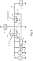
- the electrical system comprises the following elements: an electric power producer 1 (for example, an alternator), a starter 2, a first electric energy store 3, the energy transfer management device electrical 5, a main vehicle network 4a of a vehicle and possibly a secondary edge network 4b, and a second energy store 6.
- the electrical energy transfer management device 5 comprises four terminals: firstly, a first terminal M, which is a negative terminal connected to a vehicle ground, and secondly, a second terminal P1, a third terminal terminal P2 and a fourth terminal P3 which are positive terminals.
- the electric power producer 1 is electrically connected on one side to the second terminal P1 of the device 5, with an electrical harness (resistive and inductive), and on the other side to ground.
- the alternator 2 is also electrically connected on one side to the second terminal P1 of the device 5, with an electrical harness (resistive and inductive), and on the other side to ground.
- the secondary edge network 4b is also electrically connected on one side to the second terminal P1 of the device 5, with an electrical harness (resistive and inductive), and on the other side to ground.
- the first electrical energy store 3 is also electrically connected on one side to the second terminal P1 of the device 5 and on the other side to ground.
- the main edge network 4a is electrically connected on one side to the third terminal P2 of the device 5 with at least one beam and on the other side to ground.
- the second storage unit 6 is electrically connected on one side to the fourth terminal P3 of the device 5 and on the other side to ground with beams.
- the alternator 1 (or alternator-starter) is used for the supply of electrical power to the vehicle onboard network 4a, 4b, for restarting the engine and for the so-called BOOST phases.
- the alternator is used to provide torque to the engine during the driving phase. In the BOOST phase, the alternator thus becomes a current consumer.
- the starter 2 is used for the first start of the vehicle and possibly, depending on the configuration of the vehicle, for reboots of the vehicle.
- the first electrical energy store 3, for example of the 12V lead battery type, is used in particular for start-up and restart, for the consumer power supply of the main on-board network 4a and the secondary 4b during the standby phases of the vehicle.
- the vehicle also comprises a sensor 8 collecting data relating to the first storer 3: the current of the first storer 3, the voltage of the first storer 3, the temperature of the first storer 3, an estimation of the state of charge of the first storer 3.
- a sensor 8 collecting data relating to the first storer 3: the current of the first storer 3, the voltage of the first storer 3, the temperature of the first storer 3, an estimation of the state of charge of the first storer 3.
- the first storer 3 is instrumented (measurement of current and voltage), it is possible to use this information.
- the main onboard network 4a includes electrical elements of the vehicle such as computers and electrical equipment, for example, comfort equipment, security organs and other electrical equipment not falling into the categories mentioned above.
- the vehicle comprises a secondary edge network 4b comprising only consumers (or organs) that are not disturbed during the startup, restart and BOOST phases.
- the second storer 6 (or secondary storer), for example a lithium-ion battery, is used to feed the main on-board network 4a during the use of the vehicle (off-standby).
- the vehicle also includes a supervisor 7 capable of collecting and transmitting data from the vehicle.
- the vehicle also comprises a sensor 8 collecting data relating to the first storer 3: the current of the first storer 3, the voltage of the first storer 3, the temperature of the second storer 3, an estimation of the state of charge of the second storer 3.
- the vehicle also comprises electrical distribution elements 10, 11, 12.
- These electrical distribution elements 10, 11, 12 are example beams having inductive and resistive characteristics. The beams contribute to the good functioning of the system thanks to their resistive and inductive characteristic.
- the device 5 further comprises inductances (R, L) of the order of a few ⁇ H (for example less than 10 ⁇ H) in the case where the inductive effect of the beams is not not enough when controlling PWM switches.
- inductances R, L
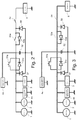
- the architecture of the figure 7 is a simplified version of the architecture of the figure 1 (for ease of understanding) and for which, two inductances have been added: a first inductor L1 and a second inductor L2. These two inductances are added to compensate for an insufficient inductive effect of the beams. This phenomenon can occur especially if the beams are relatively short (a few centimeters).
- the device 5 comprises two main switches 51, 53, also called power switches, (for example of the Metal Oxide Semiconductor Field Effect Transistor (MOSFET) type), which is translated by a metal-oxide-semiconductor field effect transistor. ):
- the first main switch 51 is composed of a first elementary switch 51a, a second elementary switch 51b and a first diode 51c.
- the first diode 51c is put in place for the safety of operation. Indeed the first diode 51c is used to feed the main network 4a if there is an open circuit failure of the second elementary switch 51b, 53, and / or 54 To confirm. In fact, if the system is in a discharge phase of the second storage unit 6 in the main network 4a and the second main switch 53 and / or the electromechanical switch 54 become out of service open, then as the first elementary switch 51a and the second switch 51b are driven open, the current will pass through the first diode 51c to supply the main edge network 4a.
- the first elementary switch 51a is normally closed. It is used to power the vehicle during a parking phase of the vehicle (vehicle standby).
- the second elementary switch 51b is controllable in voltage and current in the transfer of electrical energy (from the voltage and current setpoint for the construction of the PWM signal). As long as the current, the voltage and the power are in a mask defined by limiting values, there is no voltage clipping, limitation of the current or limitation of the power and the second elementary switch 51b is has a closed switch If the current, voltage, or power is beyond the defined pattern, there is voltage clipping, or current limiting or power limitation, and the second elementary switch 51b behaves as a one-way chopper.
- the control of 51b makes it possible to set up a current limitation in the direction of the second storage unit 6 towards the assembly comprising the first storage unit 3 and the alternator-starter 1 under tension stress of the main on-board network 4a (of to maintain a minimum voltage in the main edge network 4a).
- This current limitation is used to contribute to the BOOST function and supply current to the alternator-starter 1 which then contributes to providing torque to the engine during the vehicle running phase.
- the control 51b does not allow limitation of the current in the direction of the first storer 3 to the second storer 6 in particular because of the first diode.
- the second main switch 53 comprises a third switch 53a and a second diode 53b.
- the third switch 53a is controllable in voltage and current in the transfer of electrical energy (from the voltage and current setpoint for the construction of the PWM). As long as the current, voltage and power are in a template defined by limiting values, there is no voltage clipping, current limitation or power limitation and the third switch 53a behaves as a closed switch. If the current, voltage, or power is beyond the defined pattern, there is voltage clipping, or current limiting or power limitation, and the third switch 53a behaves as a one-way chopper.
- the control of the third switch 53a does not allow limitation of the current in the direction of the second storage unit 6 to the assembly comprising the first storage unit 3 the starter 1 and the alternator 2.
- the second diode 53b is put in place for the safety of operation.
- the second diode 53b supplies power to the main on-board network 4a if there is an open circuit failure of [51b], [53a] and [51c].
- the second elementary switch 51b and the third elementary switch 53a each behave as a monodirectional chopper.
- the device 5 overall, behaves as a bidirectional step-down.
- the device according to the invention also comprises a normally open electromechanical switch 54 enabling the second storage unit 6 to be isolated, for example if the conditions at the limits of the second storage unit 6 are reached (durability of the storer). It is also open when the vehicle is Standby: The lithium battery is not used during vehicle standby or main switch 53 failure in the state closed (always passing).
- the invention also comprises a filtering capacitor 52 connected on the one hand to the third terminal P2 and the first terminal M.
- the main switches 51 and 53 have an unconventional positioning in an electrical architecture of a vehicle.
- the diodes are common cathode with all or part of the 12V electrical network 12a connected to these cathodes.
- the main edge network is connected to the cathodes of the diodes 51c, 53c.
- the positioning of the main switches 51, 53 and diodes 51c, 53b makes it possible to ensure that the main edge network 4a can be powered regardless of the control mode of the elementary switches 51a, 51b, 53b thanks to the diodes 51c, 53c .
- the invention also comprises three voltage measurements 55a, 55b, 55c.
- the first voltage measurement 55a measures the voltage of the first storage unit 3 between the second terminal P1 and the first terminal M.
- the second voltage measurement 55b measures the voltage of the main edge network 4a between the third terminal P2 and the second terminal M.
- the third voltage measurement 55c measures the potential difference between, on the one hand, the first main switch 53 and the electromechanical switch 54 (positive potential) and, on the other hand, the terminal M (negative potential).
- the device according to the invention 5 also comprises two freewheeling diodes 56, 57.
- the first freewheeling diode 56 is indispensable during operation in PWM, otherwise the voltage becomes too high on the second storage unit 6, due to the inductive effects.
- the second freewheeling diode 57 is essential during operation in PWM, otherwise the voltage becomes too high on the first storage 3 (not starting, restarting). Without diode, overvoltages can destroy switches If the elementary switches 51b, 53a are not driven in PWM, the free wheel diodes 56, 57 are not mandatory. Indeed, the architecture according to the invention makes it possible to work in PWM (with diodes) or without PWM (without diode).
- the figure 8 shows a simplified embodiment of the invention which differs from that of the figure 1 in that it comprises only the first freewheeling diode 56 and does not include a second freewheeling diode 57.
- the device according to the invention 5 also comprises a supervisor 58.
- the supervisor 58 is configured to generate a control signal C1, C2, corresponding to the determined operating mode, for the second elementary switch 51b and the third elementary switch 53a. These control signals make it possible to open and close the switches 51b, 53a in order to regulate the values of the voltage and the current associated with the transfer of energy when a limitation of the current and / or of the voltage is necessary.
- the alternator 1 communicates [a] with the vehicle supervisor 7.
- the alternator 1 sends the vehicle supervisor 7 alternator data with for example the load of the alternator.
- the vehicle supervisor 7 sends to the alternator 1 control instructions of the alternator.
- the main on-board network 4a sends [b] to the vehicle supervisor 7 information concerning the state of the electric consumers present on the main on-board network 4a. More specifically, it is certain constituents (consumers) of the main shipboard 4a that send information to the supervisor 7. This information enables the vehicle supervisor 7 to determine a nominal operating voltage range of the main on-board network 4a by defining a minimum voltage (Umin) and a maximum voltage (Umax) to be guaranteed.
- Umin minimum voltage
- Umax maximum voltage
- the secondary edge network 4b sends [c] to the vehicle supervisor 7 information concerning the state of the electrical consumers present on the secondary edge network 4b. More specifically, it is certain constituents (consumers) of the secondary on-board network 4b that send information to the supervisor 7. This information enables the vehicle supervisor 7 to determine a nominal operating voltage range of the secondary edge network 4b by defining a minimum voltage (Umin) and a maximum voltage (Umax) to be guaranteed.
- Umin minimum voltage
- Umax maximum voltage
- the first storer communicates [d] to the vehicle supervisor 7 information concerning the first storer 3, at a minimum: the temperature of the first storer, the current of the first storer, the voltage of the first storer, estimation of the state of charge of the first storer .
- the supervisor of the device 5 receives [e] the first voltage measurement 55a between P1 and M. This measurement represents the voltage of the first storage 3 (it is a picture at the voltage drop ready).
- the supervisor 58 of the device 5 receives [f] the first current measurement 50a in the main edge network direction 4a to the first storage unit 3 on the second terminal P1 of the device 5.
- the supervisor 58 of the device 5 controls [g] the first elementary switch 51a.
- the supervisor 58 of the device 5 also drives [h] the second elementary switch 51b.
- This is an ON type control (that is, in bidirectional mode), OFF (that is, blocked in the direction of the secondary edge 4b to the main edge 4a and can be passed in the direction of the first storer 3 to main trunk network 4a through first diode 51c or switched (PWM) in current limiting mode in the direction of second storer 6 to first storer 3 and passing in the storage direction 3 to the edge network 4a.
- ON type control that is, in bidirectional mode
- OFF that is, blocked in the direction of the secondary edge 4b to the main edge 4a and can be passed in the direction of the first storer 3 to main trunk network 4a through first diode 51c or switched (PWM) in current limiting mode in the direction of second storer 6 to first storer 3 and passing in the storage direction 3 to the edge network 4a.
- PWM switched
- the supervisor 58 of the device 5 receives [i] the second measurement of voltage between P2 and M. This measurement represents the voltage of the main edge network 4a.
- the supervisor 58 of the device 5 pilot [j] the third elementary switch 53a.
- This is an ON type control (that is, switching regardless of the direction of the current and the current value), OFF or switching mode (PWM) in charge current limiting mode of the second storage unit 6 in the alternator direction 1 to second storer 6.
- PWM switching mode
- the supervisor 58 of the device 5 also controls [k] the electromechanical switch 54.
- the supervisor 58 of the device 5 receives [1] the second current measurement 50b of the second storage unit 6.
- the supervisor 58 of the device 5 receives [m] the third voltage measurement 55c This measurement represents the voltage of the second storage unit 6.
- the vehicle supervisor 7 and the supervisor 58 of the device 5 exchange information [n] .
- the vehicle supervisor 7 requests the supervisor 58 of the device 5 to contribute to the BOOST mode.
- the supervisor of the device 58 sends the vehicle supervisor 7 diagnostic information of the system: for example the states of the switches. This makes it possible to define the adapted driving mode. If there is a switch off: we switch to a degraded mode.
- the second storer communicates [o] to the vehicle supervisor 7 information concerning the second storer 6, for example: the temperature of the second storer, the current of the second storer, the voltage of the second storer, estimation of the state of charge of the second storer .
- the figure 2 shows a first mode of operation of the system according to the invention.
- the first elementary switch 51a is open
- the second elementary switch 51b is closed
- the third elementary switch 53a is open
- the electromechanical switch 54 is open.
- This mode of operation makes it possible to feed the main on-board networks 4a and 4b from the first storer 3.
- the figure 3 shows a second mode of operation of the system according to the invention.
- the first elementary switch 51a is open
- the second elementary switch 51b is driven in PWM
- the third elementary switch 53a is closed
- the electromechanical switch 54 is closed.
- This operating mode makes it possible to contribute to the BOOST function by exploiting the two storers 3, 6 with a limitation of the current supplied by the second storer 6 to the alternator-starter 1 so as to maintain a minimum voltage for the main on-board network 4a.
- This current limitation is obtained by controlling the second elementary switch 51b PWM driven by the supervisor 58 of the device 5, from a maximum current setpoint.
- the figure 4 represents four diagrams showing the evolution of different intensity and voltage measurements over time. The curves are divided into four diagrams for easy reading.
- a first curve (I_BOOST) represents the evolution of the input current of the alternator 1.
- a second curve (I_stacker 1) represents the evolution of the output current of the first storage unit 3.
- a third curve (lin_DCDC) represents the evolution current at the second terminal P1.
- a fourth curve (I_RDB) represents the evolution of the input current of the on-board network, in other words at the third terminal P2.
- a fifth curve (I_stacker2) represents the evolution of the output current of the second storage unit 6, in other words at the fourth terminal P3.
- a sixth curve (V_RDB) shows the evolution of the voltage at the edge network 4a.
- a seventh curve represents the evolution of intensity at the level of capacity 52.
- the main edge network 4a is fed exclusively by the first storer 3.
- the output current of the second storer 6 is substantially zero.
- the current at the second terminal P1 (lin_DCDC) is of the order of -20A).
- the output current of the first storage 3 is substantially equal to the input current of the main edge network 4a, of the order of 20A.
- the voltage at the level of the onboard network is of the order of 12v.
- the intensity at the level of the capacitor 52 is zero.
- the intensity at the alternator-starter gradually increases to 140A.
- the output intensity of the second storer 6 increases to about 100A.
- the intensity at the second terminal P1 is of the order of 80A.
- the output intensity of the first storer 3 is of the order of 60A.
- the input current of the main edge network 4a is always of the order of 20A.
- the inductive effects, generated by PWM control of the switch, cause voltage variations at the level of the on-board network (of the order of +/- 1V). These variations are relatively thanks to the capacity 52 which plays a role of filter and whose intensity varies between 40a and 40a
- the output current of the second storage unit 6 again becomes substantially zero.
- the current at the second terminal P1 also substantially becomes again of the order of -20A.
- the output current of the first storer 3 becomes gradually substantially equal to the input current of the main edge network 4a, of the order of 20A.
- the voltage at the level of the onboard network is of the order of 12v.
- the intensity at the level of the capacitance 52 becomes zero again.
- the input current of the main edge network 4a is always (before, during and after the activation of the BOOST) of the order of 20A. This is the desired effect: the operation of the onboard network is not affected by the activation of the BOOST.
- the figure 5 shows a third mode of operation of the system according to the invention. This is a refill of the second storer 6 with the application of a slope current directive to limit disturbances.
- the first elementary switch 51a is open, the second elementary switch 51b is controlled in OFF or in PWM.
- the third elementary switch 53a is driven in PWM.
- the electromechanical switch 54 is closed.
- the assembly comprising the first storage unit 3 and the alternator 1 supplies the main on-board network 4a and recharges the second storage unit 6.
- the figure 6 represents two diagrams, a first diagram showing the evolution of different voltage measurements over time and a second diagram showing the evolution of different intensity measurements over time.
- a first curve represents the evolution of the voltage at the main edge network 4a.
- a second curve represents the evolution of the voltage at the second storer 6.
- a third curve (I_Stocker1) represents the evolution of the current flowing through P1.
- a fourth curve (I_RDB) represents the evolution of the input current of the on-board network principal 4a.
- a fifth curve (I_stacker2) represents the evolution of the output current of the second storage unit 6.
- the main edge network 4a is fed exclusively by the first storer 3.
- the output current of the second storer 6 is substantially zero.
- the output current of the first storage 3 is substantially equal to the input current of the main edge network 4a, of the order of 20A.
- the voltage at the second storer 6 is 10V.
- the voltage at the on-board level is 14V.
- the intensity at the first storer gradually increases to 90A.
- the intensity at the second storer 6 increases to about 90A.
- the intensity at the main edge network 4a remains constant around 20A.
- the voltage at the second storage unit 6 remains around 10V (the charging current of the second storage unit 6 has reached the current limitation setpoint, therefore, there is a limitation of current, which is why it is around 10V ).
- the voltage at the on-board network remains around 14V "oscillating" by plus or minus 1V (without the filtering capacitor 52, there would be more oscillation.It is thanks to the capacitor 52 that the ripple is controlled) . This is the effect of the third PWM-controlled switch 53b which limits the charging current of the second storage unit 6.
- a third phase corresponding to the deactivation of the recharge of the second storer 6, the current at the second storer 6 becomes substantially zero again.
- the output current of the first storer 3 becomes gradually substantially equal to the input current of the main edge network 4a, of the order of 20A.
- the input current of the main edge network 4a is always (before, during and after activation of the recharge) of the order of 20A. This is the desired effect: the operation of the onboard network is not affected by the activation of the refill of the second storer 6.
- the voltage at the second storage 6 is 10V, which corresponds to a very unloaded storage.
- the voltage at the on-board level is 14V.
Landscapes
- Engineering & Computer Science (AREA)
- Power Engineering (AREA)
- Mechanical Engineering (AREA)
- Charge And Discharge Circuits For Batteries Or The Like (AREA)
- Control Of Eletrric Generators (AREA)
Claims (9)
- Vorrichtung (5) zur Leistungsübertragungsverwaltung, die eine erste Klemme (M) umfasst, die dazu bestimmt ist, mit einer elektrischen Masse verbunden zu sein, eine zweite Klemme (P1), die dazu bestimmt ist, mit einem ersten Speicher (3) elektrischer Energie verbunden zu sein, eine dritte Klemme (P2), die dazu bestimmt ist, mit mindestens einem Stromverbraucher verbunden zu sein, eine vierte Klemme (P3), die dazu bestimmt ist, mit einem zweiten Speicher (6) elektrischer Energie verbunden zu sein, wobei die Vorrichtung (5) einen ersten Hauptschalter (51) umfasst, der einerseits mit der zweiten Klemme (P1) und andererseits mit der dritten Klemme (P2) verbunden ist, einen zweiten Hauptschalter (53), der einerseits mit der vierten Klemme (P3) und andererseits mit der dritten Klemme (P2) verbunden ist, wobei der erste Hauptschalter (51) eine erste Diode (51c) umfasst, deren Kathode mit der dritten Klemme (P2) verbunden ist, wobei der zweite Hauptschalter (53) eine zweite Diode (53b) umfasst, deren Kathode mit der dritten Klemme (P2) verbunden ist, wobei der zweite Hauptschalter (53) außerdem einen dritten elementaren Schalter (53a) umfasst, der mit der zweiten Diode (53b) parallel geschaltet ist, dadurch gekennzeichnet, dass sie außerdem Folgendes umfasst:- einen Supervisor (58) der geeignet ist, ein moduliertes Signal zu dem dritten elementaren Schalter (53a) derart zu liefern, dass der Strom, der durch den dritten elementaren Schalter (53a) durchgeht, begrenzt wird, wobei der dritte elementare Schalter (53a) angepasst ist, um von einem Signal in Impulsbreitenmodulation gesteuert zu werden.- eine erste Freilaufdiode (56), deren Anode mit der ersten Klemme (M) verbunden ist, und die Kathode mit der Anode der zweiten Diode (53b) verbunden ist,- eine Kapazität (52), die einerseits mit der dritten Klemme (P2) und andererseits mit der ersten Klemme (M) verbunden ist.
- Vorrichtung (5) zur Leistungsübertragungsverwaltung nach Anspruch 1, dadurch gekennzeichnet, dass der erste Hauptschalter (51) außerdem einen ersten elementaren Schalter (51a) umfasst, der zwischen der zweiten Klemme (P1) und der dritten Klemme (P2) positioniert ist.
- Vorrichtung (5) zur Leistungsübertragungsverwaltung nach einem der Ansprüche 1 oder 2, dadurch gekennzeichnet, dass der erste Hauptschalter (51) außerdem einen zweiten elementaren Schalter (51b) umfasst, der mit der ersten Diode (51c) parallel geschaltet ist.
- Vorrichtung (5) zur Leistungsübertragungsverwaltung nach Anspruch 3, dadurch gekennzeichnet, dass der Supervisor (58) außerdem geeignet ist, Folgendes zu liefern:- ein moduliertes Signal zu dem zweiten elementaren Schalter (51b) derart, dass der Strom, der durch den zweiten elementaren Schalter (51b) durchgeht, begrenzt wird, wobei der zweite elementare Schalter (51b) angepasst ist, um von einem Signal in Impulsbreitenmodulation gesteuert zu sein.
- Vorrichtung zur Leistungsübertragungsverwaltung nach Anspruch 4, dadurch gekennzeichnet, dass sie außerdem Folgendes umfasst:- eine zweite Freilaufdiode (57), deren Anode mit der ersten Klemme (M) verbunden ist, und die Kathode mit der Anode der zweiten Klemme (51c).
- Vorrichtung (5) zur Leistungsübertragungsverwaltung nach Anspruch 5, dadurch gekennzeichnet, dass sie außerdem einen elektromechanischen Schalter (54) umfasst, der einerseits zwischen der vierten Klemme (P3) und andererseits einer Anordnung, die die Anode der zweiten Diode (53b) umfasst, und der Kathode der ersten Freilaufdiode (56) positioniert ist.
- Vorrichtung (5) zur Leistungsübertragungsverwaltung nach dem vorstehenden Anspruch, dadurch gekennzeichnet, dass sie außerdem Folgendes umfasst:- eine erste Induktanz (L1), die einerseits zwischen der zweiten Klemme (P1) und andererseits der Anordnung, die die Anode der ersten Diode (51c) umfasst, und der Kathode der zweiten Freilaufdiode (57) positioniert ist, und- eine zweite Induktanz (L2), die einerseits zwischen der vierten Klemme (P3) und andererseits der Anordnung, die die Anode der zweiten Diode (53b) umfasst, und der Kathode der ersten Freilaufdiode (56) positioniert ist.
- Elektrisches System eines Fahrzeugs, das einen Energieerzeuger (1), einen ersten Energiespeicher (3), einen zweiten Energiespeicher (6) und ein Hauptbordnetz (4a) umfasst, das mindestens einen Stromverbraucher umfasst, dadurch gekennzeichnet, dass es außerdem eine Vorrichtung (5) zur Leistungsübertragungsverwaltung nach einem der vorstehenden Ansprüche umfasst, wobei die zweite Klemme (P1) mit dem ersten Speicher (3) verbunden ist, die dritte Klemme (P2) mit dem Bordnetz (4a) verbunden ist, die vierte Klemme (P3) mit dem zweiten Speicher (6) verbunden ist, wobei die erste Klemme (M) mit einer elektrischen Masse des Fahrzeugs verbunden ist, wobei der Energieerzeuger (1) mit der zweiten Klemme (P1) oder mit der dritten Klemme (P2) verbunden ist.
- Fahrzeug, das eine Vorrichtung (5) zur Leistungsübertragungsverwaltung nach einem der Ansprüche 1 bis 7 oder ein elektrisches System nach Anspruch 8 umfasst.
Applications Claiming Priority (2)
| Application Number | Priority Date | Filing Date | Title |
|---|---|---|---|
| FR1459489A FR3026903B1 (fr) | 2014-10-03 | 2014-10-03 | Dispositif de gestion de transfert d'energie ameliore |
| PCT/FR2015/052643 WO2016051104A1 (fr) | 2014-10-03 | 2015-10-02 | Dispositif de gestion de transfert d'énergie améliore |
Publications (2)
| Publication Number | Publication Date |
|---|---|
| EP3202015A1 EP3202015A1 (de) | 2017-08-09 |
| EP3202015B1 true EP3202015B1 (de) | 2019-01-23 |
Family
ID=52423841
Family Applications (1)
| Application Number | Title | Priority Date | Filing Date |
|---|---|---|---|
| EP15791683.4A Active EP3202015B1 (de) | 2014-10-03 | 2015-10-02 | Verbesserte vorrichtung zur leistungsübertragungsverwaltung |
Country Status (4)
| Country | Link |
|---|---|
| EP (1) | EP3202015B1 (de) |
| CN (1) | CN107078536B (de) |
| FR (1) | FR3026903B1 (de) |
| WO (1) | WO2016051104A1 (de) |
Families Citing this family (3)
| Publication number | Priority date | Publication date | Assignee | Title |
|---|---|---|---|---|
| FR3047367B1 (fr) * | 2016-01-29 | 2018-02-16 | Peugeot Citroen Automobiles Sa | Dispositif de gestion de transfert d’energie avec controle actif des perturbations electromagnetiques |
| DE102020111266A1 (de) * | 2020-04-24 | 2021-10-28 | Bayerische Motoren Werke Aktiengesellschaft | Trennvorrichtung und Energieversorgungsnetz für ein Kraftfahrzeug |
| FR3132677A1 (fr) * | 2022-02-17 | 2023-08-18 | Psa Automobiles Sa | Gestion optimisée d’un groupe d’alimentation électrique à deux batteries de servitude d’un système |
Family Cites Families (7)
| Publication number | Priority date | Publication date | Assignee | Title |
|---|---|---|---|---|
| DE19842657A1 (de) * | 1998-09-17 | 2000-03-23 | Volkswagen Ag | Zwei-Batteriesystem |
| DE102009000046A1 (de) * | 2009-01-07 | 2010-07-08 | Robert Bosch Gmbh | Bordnetz für ein Fahrzeug mit Start-Stopp-System |
| JP5578014B2 (ja) * | 2010-10-19 | 2014-08-27 | 株式会社デンソー | バッテリシステム制御装置 |
| JP5541134B2 (ja) | 2010-12-13 | 2014-07-09 | 株式会社デンソー | 電源装置 |
| GB2488968A (en) * | 2011-02-01 | 2012-09-19 | Land Rover Uk Ltd | Vehicle power management using diodes |
| DE102011012958A1 (de) * | 2011-02-03 | 2012-03-22 | Audi Ag | Energiespeichersystem mit einem Lithium-Ionen-Kondensator |
| FR3001931A1 (fr) * | 2013-02-14 | 2014-08-15 | Peugeot Citroen Automobiles Sa | Dispositif de gestion de transfert d'energie depuis et vers un stockeur d'energie electrique d'un vehicule |
-
2014
- 2014-10-03 FR FR1459489A patent/FR3026903B1/fr not_active Expired - Fee Related
-
2015
- 2015-10-02 EP EP15791683.4A patent/EP3202015B1/de active Active
- 2015-10-02 WO PCT/FR2015/052643 patent/WO2016051104A1/fr not_active Ceased
- 2015-10-02 CN CN201580053441.0A patent/CN107078536B/zh not_active Expired - Fee Related
Non-Patent Citations (1)
| Title |
|---|
| None * |
Also Published As
| Publication number | Publication date |
|---|---|
| CN107078536A (zh) | 2017-08-18 |
| EP3202015A1 (de) | 2017-08-09 |
| WO2016051104A1 (fr) | 2016-04-07 |
| FR3026903B1 (fr) | 2018-03-23 |
| CN107078536B (zh) | 2020-01-14 |
| FR3026903A1 (fr) | 2016-04-08 |
Similar Documents
| Publication | Publication Date | Title |
|---|---|---|
| EP2532069B1 (de) | Ladungsausgleichssystem für batterien | |
| EP0325520B1 (de) | Kraftfahrzeugversorgungsschaltung mit zwei Betriebsspannungen | |
| EP0847124B1 (de) | Notstromversorgungseinrichtung zur provisorischen Stromversorgung im Falle eines Versagens der Hauptstromversorgung | |
| FR2972581A1 (fr) | Systeme d'equilibrage de charge pour batteries | |
| EP3202015B1 (de) | Verbesserte vorrichtung zur leistungsübertragungsverwaltung | |
| FR2782582A1 (fr) | Installation d'alimentation electrique, notamment pour le reseau embarque d'un vehicule | |
| EP1750343B1 (de) | Elektronischer Auslöser mit einer Stromversorgungsschaltung einschliesslich Spannungserhöhungsmittel und Leistungschalter mit solchem Auslöser | |
| WO2016097551A1 (fr) | Procede et dispositif de diagnostic d'un dispositif de gestion de l'energie electrique | |
| FR2917253A1 (fr) | Procede de commande d'une machine electrique tournante en cas de delestage de charge, et module de commande et de puissance correspondant | |
| EP2788228A1 (de) | Verfahren zur verwaltung der elektrischen energie eines kraftfahrzeugs und kraftfahrzeug mit diesem verfahren | |
| FR2995154A1 (fr) | Circuit electrique d'un vehicule automobile | |
| EP3408920B1 (de) | Energieübertragungssteuerungsvorrichtung mit aktiver steuerung von elektromagnetischer interferenz | |
| WO2015015115A1 (fr) | Système de gestion d'une tension d'alimentation d'un réseau électrique de bord de véhicule automobile | |
| FR3162728A1 (fr) | Système de dégivrage des pales de l’hélice d’un aéronef comprenant un enroulement primaire de mesure | |
| EP1946972A1 (de) | Vorrichtung zur vorübergehenden Erhöhung der elektrischen Spannung für Automobilelement | |
| EP2179502B1 (de) | Stromversorgungseinheit für ein hausautomatisierungsstellglied und verfahren zum betrieb der einheit | |
| CA2748227A1 (fr) | Systeme de conversion d`energie electrique | |
| EP4014309B1 (de) | Induktive halteschaltung | |
| WO2007080349A1 (fr) | Dispositif d'alimentation de l'inducteur d'une machine electrique tournante | |
| FR2973600A1 (fr) | Dispositif de regulation en tension, reversible en courant et une architecture electrique destine a equiper un vehicule automobile comprenant un tel dispositif | |
| EP2843816A1 (de) | Stromzuführung mit Partitionierung mit modulierbarem Aufbau | |
| WO2014135778A1 (fr) | Dispositif d'alimentation commute pour le réseau de bord d'un véhicule automobile | |
| EP2337199A1 (de) | Wandlerschaltung für sehr niedrige spannung | |
| FR3019396A1 (fr) | Systeme de stabilisation de tension | |
| EP2602910A1 (de) | Schnittstellenvorrichtung zwischen einem elektrischen Netz und Verbrauchersystemen |
Legal Events
| Date | Code | Title | Description |
|---|---|---|---|
| STAA | Information on the status of an ep patent application or granted ep patent |
Free format text: STATUS: THE INTERNATIONAL PUBLICATION HAS BEEN MADE |
|
| PUAI | Public reference made under article 153(3) epc to a published international application that has entered the european phase |
Free format text: ORIGINAL CODE: 0009012 |
|
| STAA | Information on the status of an ep patent application or granted ep patent |
Free format text: STATUS: REQUEST FOR EXAMINATION WAS MADE |
|
| 17P | Request for examination filed |
Effective date: 20170314 |
|
| AK | Designated contracting states |
Kind code of ref document: A1 Designated state(s): AL AT BE BG CH CY CZ DE DK EE ES FI FR GB GR HR HU IE IS IT LI LT LU LV MC MK MT NL NO PL PT RO RS SE SI SK SM TR |
|
| AX | Request for extension of the european patent |
Extension state: BA ME |
|
| RAP1 | Party data changed (applicant data changed or rights of an application transferred) |
Owner name: PSA AUTOMOBILES SA |
|
| DAV | Request for validation of the european patent (deleted) | ||
| DAX | Request for extension of the european patent (deleted) | ||
| GRAP | Despatch of communication of intention to grant a patent |
Free format text: ORIGINAL CODE: EPIDOSNIGR1 |
|
| STAA | Information on the status of an ep patent application or granted ep patent |
Free format text: STATUS: GRANT OF PATENT IS INTENDED |
|
| INTG | Intention to grant announced |
Effective date: 20180829 |
|
| GRAS | Grant fee paid |
Free format text: ORIGINAL CODE: EPIDOSNIGR3 |
|
| GRAA | (expected) grant |
Free format text: ORIGINAL CODE: 0009210 |
|
| STAA | Information on the status of an ep patent application or granted ep patent |
Free format text: STATUS: THE PATENT HAS BEEN GRANTED |
|
| AK | Designated contracting states |
Kind code of ref document: B1 Designated state(s): AL AT BE BG CH CY CZ DE DK EE ES FI FR GB GR HR HU IE IS IT LI LT LU LV MC MK MT NL NO PL PT RO RS SE SI SK SM TR |
|
| REG | Reference to a national code |
Ref country code: GB Ref legal event code: FG4D Free format text: NOT ENGLISH |
|
| REG | Reference to a national code |
Ref country code: CH Ref legal event code: EP |
|
| REG | Reference to a national code |
Ref country code: DE Ref legal event code: R096 Ref document number: 602015023752 Country of ref document: DE |
|
| REG | Reference to a national code |
Ref country code: AT Ref legal event code: REF Ref document number: 1092215 Country of ref document: AT Kind code of ref document: T Effective date: 20190215 |
|
| REG | Reference to a national code |
Ref country code: IE Ref legal event code: FG4D Free format text: LANGUAGE OF EP DOCUMENT: FRENCH |
|
| REG | Reference to a national code |
Ref country code: NL Ref legal event code: MP Effective date: 20190123 |
|
| REG | Reference to a national code |
Ref country code: DE Ref legal event code: R084 Ref document number: 602015023752 Country of ref document: DE |
|
| PG25 | Lapsed in a contracting state [announced via postgrant information from national office to epo] |
Ref country code: NL Free format text: LAPSE BECAUSE OF FAILURE TO SUBMIT A TRANSLATION OF THE DESCRIPTION OR TO PAY THE FEE WITHIN THE PRESCRIBED TIME-LIMIT Effective date: 20190123 |
|
| REG | Reference to a national code |
Ref country code: GB Ref legal event code: 746 Effective date: 20190617 |
|
| PG25 | Lapsed in a contracting state [announced via postgrant information from national office to epo] |
Ref country code: PT Free format text: LAPSE BECAUSE OF FAILURE TO SUBMIT A TRANSLATION OF THE DESCRIPTION OR TO PAY THE FEE WITHIN THE PRESCRIBED TIME-LIMIT Effective date: 20190523 Ref country code: ES Free format text: LAPSE BECAUSE OF FAILURE TO SUBMIT A TRANSLATION OF THE DESCRIPTION OR TO PAY THE FEE WITHIN THE PRESCRIBED TIME-LIMIT Effective date: 20190123 Ref country code: SE Free format text: LAPSE BECAUSE OF FAILURE TO SUBMIT A TRANSLATION OF THE DESCRIPTION OR TO PAY THE FEE WITHIN THE PRESCRIBED TIME-LIMIT Effective date: 20190123 Ref country code: NO Free format text: LAPSE BECAUSE OF FAILURE TO SUBMIT A TRANSLATION OF THE DESCRIPTION OR TO PAY THE FEE WITHIN THE PRESCRIBED TIME-LIMIT Effective date: 20190423 Ref country code: FI Free format text: LAPSE BECAUSE OF FAILURE TO SUBMIT A TRANSLATION OF THE DESCRIPTION OR TO PAY THE FEE WITHIN THE PRESCRIBED TIME-LIMIT Effective date: 20190123 Ref country code: LT Free format text: LAPSE BECAUSE OF FAILURE TO SUBMIT A TRANSLATION OF THE DESCRIPTION OR TO PAY THE FEE WITHIN THE PRESCRIBED TIME-LIMIT Effective date: 20190123 Ref country code: PL Free format text: LAPSE BECAUSE OF FAILURE TO SUBMIT A TRANSLATION OF THE DESCRIPTION OR TO PAY THE FEE WITHIN THE PRESCRIBED TIME-LIMIT Effective date: 20190123 |
|
| REG | Reference to a national code |
Ref country code: AT Ref legal event code: MK05 Ref document number: 1092215 Country of ref document: AT Kind code of ref document: T Effective date: 20190123 |
|
| PG25 | Lapsed in a contracting state [announced via postgrant information from national office to epo] |
Ref country code: BG Free format text: LAPSE BECAUSE OF FAILURE TO SUBMIT A TRANSLATION OF THE DESCRIPTION OR TO PAY THE FEE WITHIN THE PRESCRIBED TIME-LIMIT Effective date: 20190423 Ref country code: IS Free format text: LAPSE BECAUSE OF FAILURE TO SUBMIT A TRANSLATION OF THE DESCRIPTION OR TO PAY THE FEE WITHIN THE PRESCRIBED TIME-LIMIT Effective date: 20190523 Ref country code: GR Free format text: LAPSE BECAUSE OF FAILURE TO SUBMIT A TRANSLATION OF THE DESCRIPTION OR TO PAY THE FEE WITHIN THE PRESCRIBED TIME-LIMIT Effective date: 20190424 Ref country code: HR Free format text: LAPSE BECAUSE OF FAILURE TO SUBMIT A TRANSLATION OF THE DESCRIPTION OR TO PAY THE FEE WITHIN THE PRESCRIBED TIME-LIMIT Effective date: 20190123 Ref country code: LV Free format text: LAPSE BECAUSE OF FAILURE TO SUBMIT A TRANSLATION OF THE DESCRIPTION OR TO PAY THE FEE WITHIN THE PRESCRIBED TIME-LIMIT Effective date: 20190123 Ref country code: RS Free format text: LAPSE BECAUSE OF FAILURE TO SUBMIT A TRANSLATION OF THE DESCRIPTION OR TO PAY THE FEE WITHIN THE PRESCRIBED TIME-LIMIT Effective date: 20190123 |
|
| REG | Reference to a national code |
Ref country code: DE Ref legal event code: R097 Ref document number: 602015023752 Country of ref document: DE |
|
| PG25 | Lapsed in a contracting state [announced via postgrant information from national office to epo] |
Ref country code: IT Free format text: LAPSE BECAUSE OF FAILURE TO SUBMIT A TRANSLATION OF THE DESCRIPTION OR TO PAY THE FEE WITHIN THE PRESCRIBED TIME-LIMIT Effective date: 20190123 Ref country code: RO Free format text: LAPSE BECAUSE OF FAILURE TO SUBMIT A TRANSLATION OF THE DESCRIPTION OR TO PAY THE FEE WITHIN THE PRESCRIBED TIME-LIMIT Effective date: 20190123 Ref country code: SK Free format text: LAPSE BECAUSE OF FAILURE TO SUBMIT A TRANSLATION OF THE DESCRIPTION OR TO PAY THE FEE WITHIN THE PRESCRIBED TIME-LIMIT Effective date: 20190123 Ref country code: CZ Free format text: LAPSE BECAUSE OF FAILURE TO SUBMIT A TRANSLATION OF THE DESCRIPTION OR TO PAY THE FEE WITHIN THE PRESCRIBED TIME-LIMIT Effective date: 20190123 Ref country code: DK Free format text: LAPSE BECAUSE OF FAILURE TO SUBMIT A TRANSLATION OF THE DESCRIPTION OR TO PAY THE FEE WITHIN THE PRESCRIBED TIME-LIMIT Effective date: 20190123 Ref country code: EE Free format text: LAPSE BECAUSE OF FAILURE TO SUBMIT A TRANSLATION OF THE DESCRIPTION OR TO PAY THE FEE WITHIN THE PRESCRIBED TIME-LIMIT Effective date: 20190123 Ref country code: AL Free format text: LAPSE BECAUSE OF FAILURE TO SUBMIT A TRANSLATION OF THE DESCRIPTION OR TO PAY THE FEE WITHIN THE PRESCRIBED TIME-LIMIT Effective date: 20190123 |
|
| PG25 | Lapsed in a contracting state [announced via postgrant information from national office to epo] |
Ref country code: SM Free format text: LAPSE BECAUSE OF FAILURE TO SUBMIT A TRANSLATION OF THE DESCRIPTION OR TO PAY THE FEE WITHIN THE PRESCRIBED TIME-LIMIT Effective date: 20190123 |
|
| PLBE | No opposition filed within time limit |
Free format text: ORIGINAL CODE: 0009261 |
|
| STAA | Information on the status of an ep patent application or granted ep patent |
Free format text: STATUS: NO OPPOSITION FILED WITHIN TIME LIMIT |
|
| PG25 | Lapsed in a contracting state [announced via postgrant information from national office to epo] |
Ref country code: AT Free format text: LAPSE BECAUSE OF FAILURE TO SUBMIT A TRANSLATION OF THE DESCRIPTION OR TO PAY THE FEE WITHIN THE PRESCRIBED TIME-LIMIT Effective date: 20190123 |
|
| 26N | No opposition filed |
Effective date: 20191024 |
|
| PG25 | Lapsed in a contracting state [announced via postgrant information from national office to epo] |
Ref country code: SI Free format text: LAPSE BECAUSE OF FAILURE TO SUBMIT A TRANSLATION OF THE DESCRIPTION OR TO PAY THE FEE WITHIN THE PRESCRIBED TIME-LIMIT Effective date: 20190123 |
|
| PG25 | Lapsed in a contracting state [announced via postgrant information from national office to epo] |
Ref country code: TR Free format text: LAPSE BECAUSE OF FAILURE TO SUBMIT A TRANSLATION OF THE DESCRIPTION OR TO PAY THE FEE WITHIN THE PRESCRIBED TIME-LIMIT Effective date: 20190123 |
|
| PG25 | Lapsed in a contracting state [announced via postgrant information from national office to epo] |
Ref country code: MC Free format text: LAPSE BECAUSE OF FAILURE TO SUBMIT A TRANSLATION OF THE DESCRIPTION OR TO PAY THE FEE WITHIN THE PRESCRIBED TIME-LIMIT Effective date: 20190123 |
|
| REG | Reference to a national code |
Ref country code: CH Ref legal event code: PL |
|
| PG25 | Lapsed in a contracting state [announced via postgrant information from national office to epo] |
Ref country code: CH Free format text: LAPSE BECAUSE OF NON-PAYMENT OF DUE FEES Effective date: 20191031 Ref country code: LI Free format text: LAPSE BECAUSE OF NON-PAYMENT OF DUE FEES Effective date: 20191031 Ref country code: LU Free format text: LAPSE BECAUSE OF NON-PAYMENT OF DUE FEES Effective date: 20191002 |
|
| REG | Reference to a national code |
Ref country code: BE Ref legal event code: MM Effective date: 20191031 |
|
| PG25 | Lapsed in a contracting state [announced via postgrant information from national office to epo] |
Ref country code: BE Free format text: LAPSE BECAUSE OF NON-PAYMENT OF DUE FEES Effective date: 20191031 |
|
| PG25 | Lapsed in a contracting state [announced via postgrant information from national office to epo] |
Ref country code: IE Free format text: LAPSE BECAUSE OF NON-PAYMENT OF DUE FEES Effective date: 20191002 |
|
| PG25 | Lapsed in a contracting state [announced via postgrant information from national office to epo] |
Ref country code: CY Free format text: LAPSE BECAUSE OF FAILURE TO SUBMIT A TRANSLATION OF THE DESCRIPTION OR TO PAY THE FEE WITHIN THE PRESCRIBED TIME-LIMIT Effective date: 20190123 |
|
| PG25 | Lapsed in a contracting state [announced via postgrant information from national office to epo] |
Ref country code: MT Free format text: LAPSE BECAUSE OF FAILURE TO SUBMIT A TRANSLATION OF THE DESCRIPTION OR TO PAY THE FEE WITHIN THE PRESCRIBED TIME-LIMIT Effective date: 20190123 Ref country code: HU Free format text: LAPSE BECAUSE OF FAILURE TO SUBMIT A TRANSLATION OF THE DESCRIPTION OR TO PAY THE FEE WITHIN THE PRESCRIBED TIME-LIMIT; INVALID AB INITIO Effective date: 20151002 |
|
| PG25 | Lapsed in a contracting state [announced via postgrant information from national office to epo] |
Ref country code: MK Free format text: LAPSE BECAUSE OF FAILURE TO SUBMIT A TRANSLATION OF THE DESCRIPTION OR TO PAY THE FEE WITHIN THE PRESCRIBED TIME-LIMIT Effective date: 20190123 |
|
| REG | Reference to a national code |
Ref country code: DE Ref legal event code: R081 Ref document number: 602015023752 Country of ref document: DE Owner name: STELLANTIS AUTO SAS, FR Free format text: FORMER OWNER: PSA AUTOMOBILES SA, POISSY, FR |
|
| PGFP | Annual fee paid to national office [announced via postgrant information from national office to epo] |
Ref country code: GB Payment date: 20250923 Year of fee payment: 11 |
|
| PGFP | Annual fee paid to national office [announced via postgrant information from national office to epo] |
Ref country code: FR Payment date: 20250924 Year of fee payment: 11 |
|
| PGFP | Annual fee paid to national office [announced via postgrant information from national office to epo] |
Ref country code: DE Payment date: 20250923 Year of fee payment: 11 |