EP3202015B1 - Improved power transfer management device - Google Patents
Improved power transfer management device Download PDFInfo
- Publication number
- EP3202015B1 EP3202015B1 EP15791683.4A EP15791683A EP3202015B1 EP 3202015 B1 EP3202015 B1 EP 3202015B1 EP 15791683 A EP15791683 A EP 15791683A EP 3202015 B1 EP3202015 B1 EP 3202015B1
- Authority
- EP
- European Patent Office
- Prior art keywords
- terminal
- diode
- switch
- current
- voltage
- Prior art date
- Legal status (The legal status is an assumption and is not a legal conclusion. Google has not performed a legal analysis and makes no representation as to the accuracy of the status listed.)
- Active
Links
- 239000003990 capacitor Substances 0.000 claims description 7
- 238000004146 energy storage Methods 0.000 claims description 7
- 238000005259 measurement Methods 0.000 description 21
- 239000007858 starting material Substances 0.000 description 17
- 230000001939 inductive effect Effects 0.000 description 12
- 238000010586 diagram Methods 0.000 description 9
- WHXSMMKQMYFTQS-UHFFFAOYSA-N Lithium Chemical compound [Li] WHXSMMKQMYFTQS-UHFFFAOYSA-N 0.000 description 6
- 230000004913 activation Effects 0.000 description 6
- 229910052744 lithium Inorganic materials 0.000 description 6
- HEZMWWAKWCSUCB-PHDIDXHHSA-N (3R,4R)-3,4-dihydroxycyclohexa-1,5-diene-1-carboxylic acid Chemical compound O[C@@H]1C=CC(C(O)=O)=C[C@H]1O HEZMWWAKWCSUCB-PHDIDXHHSA-N 0.000 description 4
- 230000000694 effects Effects 0.000 description 3
- 239000004065 semiconductor Substances 0.000 description 3
- 230000002457 bidirectional effect Effects 0.000 description 2
- 239000000470 constituent Substances 0.000 description 2
- 238000010276 construction Methods 0.000 description 2
- 230000009849 deactivation Effects 0.000 description 2
- 230000005669 field effect Effects 0.000 description 2
- 238000001914 filtration Methods 0.000 description 2
- 210000000056 organ Anatomy 0.000 description 2
- HBBGRARXTFLTSG-UHFFFAOYSA-N Lithium ion Chemical compound [Li+] HBBGRARXTFLTSG-UHFFFAOYSA-N 0.000 description 1
- 238000013475 authorization Methods 0.000 description 1
- 230000001351 cycling effect Effects 0.000 description 1
- 230000001627 detrimental effect Effects 0.000 description 1
- 229910001416 lithium ion Inorganic materials 0.000 description 1
- 229910044991 metal oxide Inorganic materials 0.000 description 1
- 150000004706 metal oxides Chemical class 0.000 description 1
- 230000010355 oscillation Effects 0.000 description 1
Images


Classifications
-
- H—ELECTRICITY
- H02—GENERATION; CONVERSION OR DISTRIBUTION OF ELECTRIC POWER
- H02J—CIRCUIT ARRANGEMENTS OR SYSTEMS FOR SUPPLYING OR DISTRIBUTING ELECTRIC POWER; SYSTEMS FOR STORING ELECTRIC ENERGY
- H02J7/00—Circuit arrangements for charging or depolarising batteries or for supplying loads from batteries
- H02J7/14—Circuit arrangements for charging or depolarising batteries or for supplying loads from batteries for charging batteries from dynamo-electric generators driven at varying speed, e.g. on vehicle
- H02J7/1423—Circuit arrangements for charging or depolarising batteries or for supplying loads from batteries for charging batteries from dynamo-electric generators driven at varying speed, e.g. on vehicle with multiple batteries
-
- B—PERFORMING OPERATIONS; TRANSPORTING
- B60—VEHICLES IN GENERAL
- B60R—VEHICLES, VEHICLE FITTINGS, OR VEHICLE PARTS, NOT OTHERWISE PROVIDED FOR
- B60R16/00—Electric or fluid circuits specially adapted for vehicles and not otherwise provided for; Arrangement of elements of electric or fluid circuits specially adapted for vehicles and not otherwise provided for
- B60R16/02—Electric or fluid circuits specially adapted for vehicles and not otherwise provided for; Arrangement of elements of electric or fluid circuits specially adapted for vehicles and not otherwise provided for electric constitutive elements
- B60R16/03—Electric or fluid circuits specially adapted for vehicles and not otherwise provided for; Arrangement of elements of electric or fluid circuits specially adapted for vehicles and not otherwise provided for electric constitutive elements for supply of electrical power to vehicle subsystems or for
- B60R16/033—Electric or fluid circuits specially adapted for vehicles and not otherwise provided for; Arrangement of elements of electric or fluid circuits specially adapted for vehicles and not otherwise provided for electric constitutive elements for supply of electrical power to vehicle subsystems or for characterised by the use of electrical cells or batteries
-
- H—ELECTRICITY
- H02—GENERATION; CONVERSION OR DISTRIBUTION OF ELECTRIC POWER
- H02J—CIRCUIT ARRANGEMENTS OR SYSTEMS FOR SUPPLYING OR DISTRIBUTING ELECTRIC POWER; SYSTEMS FOR STORING ELECTRIC ENERGY
- H02J7/00—Circuit arrangements for charging or depolarising batteries or for supplying loads from batteries
- H02J7/14—Circuit arrangements for charging or depolarising batteries or for supplying loads from batteries for charging batteries from dynamo-electric generators driven at varying speed, e.g. on vehicle
- H02J7/1469—Regulation of the charging current or voltage otherwise than by variation of field
- H02J7/1492—Regulation of the charging current or voltage otherwise than by variation of field by means of controlling devices between the generator output and the battery
-
- H—ELECTRICITY
- H02—GENERATION; CONVERSION OR DISTRIBUTION OF ELECTRIC POWER
- H02J—CIRCUIT ARRANGEMENTS OR SYSTEMS FOR SUPPLYING OR DISTRIBUTING ELECTRIC POWER; SYSTEMS FOR STORING ELECTRIC ENERGY
- H02J2310/00—The network for supplying or distributing electric power characterised by its spatial reach or by the load
- H02J2310/40—The network being an on-board power network, i.e. within a vehicle
- H02J2310/46—The network being an on-board power network, i.e. within a vehicle for ICE-powered road vehicles
-
- Y—GENERAL TAGGING OF NEW TECHNOLOGICAL DEVELOPMENTS; GENERAL TAGGING OF CROSS-SECTIONAL TECHNOLOGIES SPANNING OVER SEVERAL SECTIONS OF THE IPC; TECHNICAL SUBJECTS COVERED BY FORMER USPC CROSS-REFERENCE ART COLLECTIONS [XRACs] AND DIGESTS
- Y02—TECHNOLOGIES OR APPLICATIONS FOR MITIGATION OR ADAPTATION AGAINST CLIMATE CHANGE
- Y02T—CLIMATE CHANGE MITIGATION TECHNOLOGIES RELATED TO TRANSPORTATION
- Y02T10/00—Road transport of goods or passengers
- Y02T10/80—Technologies aiming to reduce greenhouse gasses emissions common to all road transportation technologies
- Y02T10/92—Energy efficient charging or discharging systems for batteries, ultracapacitors, supercapacitors or double-layer capacitors specially adapted for vehicles
Definitions
- the invention relates to the management of the electrical energy of a vehicle in a very low voltage network (or TBT), also called 12V network.
- TBT very low voltage network
- an electrical architecture of a vehicle edge network makes it possible to make two stockists live on the same 12V network: a lead battery and a lithium battery.
- This architecture implements a first and a second MOSFET type switches each comprising a diode.
- the anode of the diode of the first switch is connected to the anode of the diode of the second switch.
- This architecture has the following drawbacks.
- the charge current of the lithium battery is not controlled. Since consumers are in parallel with the lithium battery, this architecture does not limit the current to the lithium battery pack, network system consumers. The lack of control of the charging current of the lithium battery can cause saturation of the alternator.
- an electric power management apparatus for a motor vehicle comprising: a primary power storage device for powering a motor starter device; a vehicle electrical charge; a secondary power storage device for supplying the vehicle electrical load; and a semiconductor primary diode portion coupled between the primary power storage device and the vehicle electrical load, the primary diode portion for enabling a forward current flow by itself from the primary storage device.
- primary power up to the vehicle electrical charge when the starter device is not in use and to prevent a flow of current in the opposite direction by itself from the secondary power storage device to the engine starter device when the starter is in operation. course of use.
- the invention therefore aims to overcome the aforementioned drawbacks by proposing an improved energy management device, allowing two energy storagers to coexist on a network and improving the reliability of operation of the electrical network and the stability of the power supply. on-board system voltage.
- a power transfer management device comprising a first terminal intended to be connected to an electrical mass, a second terminal intended to be connected to a first storage of electrical energy, a third terminal intended to to be connected to at least one electrical consumer, a fourth terminal intended to be connected to a second storer of electrical energy, characterized in that it comprises a first main switch connected on the one hand to the second terminal and on the other hand at the third terminal, a second main switch connected firstly to the fourth terminal and secondly to the third terminal, the first main switch having a first diode whose cathode is connected to the third terminal, the second main switch; having a second diode whose cathode is connected to the third terminal.
- connection indicates that two elements are electrically connected either directly by an electrical connection, or indirectly via one or more components (eg an inductor, a current measurement or shunt) light switch).
- components eg an inductor, a current measurement or shunt
- the element 1 is positioned between the element 2 and the element 3 indicates that the element is electrically connected to the element 2 and to the element either directly by an electrical connection, or indirectly by the intermediate of one or more component (s) (for example an inductor, a current measurement (or shunt) or a switch).
- s for example an inductor, a current measurement (or shunt) or a switch.
- common cathode switches and not common anode as in the document DE 10 2011 056 270
- the positioning the at least one electrical consumer (in particular the onboard network) between the power switches (MOSFET type for example) with common cathode diodes provides a better operating reliability. Indeed, in case of failure in the open circuit of the first switch and / or the second switch, the edge network continues to be fed via the diodes.
- the common cathode diodes allow a "natural" (non-switched) power transfer from each storer to the onboard network. The absence of switching allows an instantaneous power supply of the on-board system in case of failure, unlike a system using an emergency switch with which it is necessary to detect the failure before switching the emergency switch.
- the first main switch further comprises a first elementary switch positioned between the second terminal and the third terminal.
- the first main switch further comprises a second elementary switch, connected in parallel with the first diode.
- the second elementary switch controls the passage of the current flowing from or to the second terminal.
- the second main switch further comprises a third elementary switch, connected in parallel with the second diode.
- the control of the third elementary switch makes it possible to control the passage of the current flowing from or to the fourth terminal P3.
- the control of the second elementary switch allows a limitation of current flowing from the fourth terminal P3 to the first terminal P1 (for example to power an electrical machine connected to P1) to meet the voltage constraints of the on-board network.
- This limitation is monodirectional.
- the control of the third elementary switch allows a limitation of current flowing from the first terminal P1 to the fourth terminal P3 (for example to recharge the second storage unit from the assembly comprising the first storage unit and the alternator) while keeping a voltage respecting the voltage constraints of the on-board network.
- This limitation is monodirectional.
- This control of the charging current of the storage unit guarantees a level of voltage that complies with the quality criteria of the on-board electrical system.
- the capacity makes it possible to filter the voltage of the on-board network: to limit the variations of voltage induced by the PWM controls of the main switches. Without this, because of the inductive effects, the voltage can reach very high levels.
- the freewheel diodes also help to prevent overvoltages.
- the energy transfer management device further comprises an electromechanical switch positioned between, on the one hand, the fourth terminal and, on the other hand, an assembly comprising the anode of the second diode. and the cathode of the first freewheeling diode.
- the electromechanical switch in the open position makes it possible to isolate the second storage unit, for example if the storage limits are reached. It is also open when the vehicle is awake.
- the invention relates to an electrical system of a vehicle comprising an energy producer a first energy store, a second energy store and a main edge network comprising at least one electrical consumer characterized in that it comprises in in addition to a power transfer management device according to the invention, the second terminal being connected to the first storage unit, the third terminal being connected to the on-board network, the fourth terminal being connected to the second storage unit, the first terminal being connected to a electric mass of the vehicle, the energy producer being connected to the second terminal or the third terminal.
- the invention also relates to a vehicle comprising a power transfer management device according to the invention or an electrical system according to the invention.
- the electrical system presented is embedded in a vehicle comprising a heat engine having an edge network comprising consumers.
- the invention is not limited to this embodiment. Indeed, it relates to any electrical and electronic system comprising at least two energy storage and a consumer.
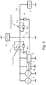
- the electrical system comprises the following elements: an electric power producer 1 (for example, an alternator), a starter 2, a first electric energy store 3, the energy transfer management device electrical 5, a main vehicle network 4a of a vehicle and possibly a secondary edge network 4b, and a second energy store 6.
- the electrical energy transfer management device 5 comprises four terminals: firstly, a first terminal M, which is a negative terminal connected to a vehicle ground, and secondly, a second terminal P1, a third terminal terminal P2 and a fourth terminal P3 which are positive terminals.
- the electric power producer 1 is electrically connected on one side to the second terminal P1 of the device 5, with an electrical harness (resistive and inductive), and on the other side to ground.
- the alternator 2 is also electrically connected on one side to the second terminal P1 of the device 5, with an electrical harness (resistive and inductive), and on the other side to ground.
- the secondary edge network 4b is also electrically connected on one side to the second terminal P1 of the device 5, with an electrical harness (resistive and inductive), and on the other side to ground.
- the first electrical energy store 3 is also electrically connected on one side to the second terminal P1 of the device 5 and on the other side to ground.
- the main edge network 4a is electrically connected on one side to the third terminal P2 of the device 5 with at least one beam and on the other side to ground.
- the second storage unit 6 is electrically connected on one side to the fourth terminal P3 of the device 5 and on the other side to ground with beams.
- the alternator 1 (or alternator-starter) is used for the supply of electrical power to the vehicle onboard network 4a, 4b, for restarting the engine and for the so-called BOOST phases.
- the alternator is used to provide torque to the engine during the driving phase. In the BOOST phase, the alternator thus becomes a current consumer.
- the starter 2 is used for the first start of the vehicle and possibly, depending on the configuration of the vehicle, for reboots of the vehicle.
- the first electrical energy store 3, for example of the 12V lead battery type, is used in particular for start-up and restart, for the consumer power supply of the main on-board network 4a and the secondary 4b during the standby phases of the vehicle.
- the vehicle also comprises a sensor 8 collecting data relating to the first storer 3: the current of the first storer 3, the voltage of the first storer 3, the temperature of the first storer 3, an estimation of the state of charge of the first storer 3.
- a sensor 8 collecting data relating to the first storer 3: the current of the first storer 3, the voltage of the first storer 3, the temperature of the first storer 3, an estimation of the state of charge of the first storer 3.
- the first storer 3 is instrumented (measurement of current and voltage), it is possible to use this information.
- the main onboard network 4a includes electrical elements of the vehicle such as computers and electrical equipment, for example, comfort equipment, security organs and other electrical equipment not falling into the categories mentioned above.
- the vehicle comprises a secondary edge network 4b comprising only consumers (or organs) that are not disturbed during the startup, restart and BOOST phases.
- the second storer 6 (or secondary storer), for example a lithium-ion battery, is used to feed the main on-board network 4a during the use of the vehicle (off-standby).
- the vehicle also includes a supervisor 7 capable of collecting and transmitting data from the vehicle.
- the vehicle also comprises a sensor 8 collecting data relating to the first storer 3: the current of the first storer 3, the voltage of the first storer 3, the temperature of the second storer 3, an estimation of the state of charge of the second storer 3.
- the vehicle also comprises electrical distribution elements 10, 11, 12.
- These electrical distribution elements 10, 11, 12 are example beams having inductive and resistive characteristics. The beams contribute to the good functioning of the system thanks to their resistive and inductive characteristic.
- the device 5 further comprises inductances (R, L) of the order of a few ⁇ H (for example less than 10 ⁇ H) in the case where the inductive effect of the beams is not not enough when controlling PWM switches.
- inductances R, L
- the architecture of the figure 7 is a simplified version of the architecture of the figure 1 (for ease of understanding) and for which, two inductances have been added: a first inductor L1 and a second inductor L2. These two inductances are added to compensate for an insufficient inductive effect of the beams. This phenomenon can occur especially if the beams are relatively short (a few centimeters).
- the device 5 comprises two main switches 51, 53, also called power switches, (for example of the Metal Oxide Semiconductor Field Effect Transistor (MOSFET) type), which is translated by a metal-oxide-semiconductor field effect transistor. ):
- the first main switch 51 is composed of a first elementary switch 51a, a second elementary switch 51b and a first diode 51c.
- the first diode 51c is put in place for the safety of operation. Indeed the first diode 51c is used to feed the main network 4a if there is an open circuit failure of the second elementary switch 51b, 53, and / or 54 To confirm. In fact, if the system is in a discharge phase of the second storage unit 6 in the main network 4a and the second main switch 53 and / or the electromechanical switch 54 become out of service open, then as the first elementary switch 51a and the second switch 51b are driven open, the current will pass through the first diode 51c to supply the main edge network 4a.
- the first elementary switch 51a is normally closed. It is used to power the vehicle during a parking phase of the vehicle (vehicle standby).
- the second elementary switch 51b is controllable in voltage and current in the transfer of electrical energy (from the voltage and current setpoint for the construction of the PWM signal). As long as the current, the voltage and the power are in a mask defined by limiting values, there is no voltage clipping, limitation of the current or limitation of the power and the second elementary switch 51b is has a closed switch If the current, voltage, or power is beyond the defined pattern, there is voltage clipping, or current limiting or power limitation, and the second elementary switch 51b behaves as a one-way chopper.
- the control of 51b makes it possible to set up a current limitation in the direction of the second storage unit 6 towards the assembly comprising the first storage unit 3 and the alternator-starter 1 under tension stress of the main on-board network 4a (of to maintain a minimum voltage in the main edge network 4a).
- This current limitation is used to contribute to the BOOST function and supply current to the alternator-starter 1 which then contributes to providing torque to the engine during the vehicle running phase.
- the control 51b does not allow limitation of the current in the direction of the first storer 3 to the second storer 6 in particular because of the first diode.
- the second main switch 53 comprises a third switch 53a and a second diode 53b.
- the third switch 53a is controllable in voltage and current in the transfer of electrical energy (from the voltage and current setpoint for the construction of the PWM). As long as the current, voltage and power are in a template defined by limiting values, there is no voltage clipping, current limitation or power limitation and the third switch 53a behaves as a closed switch. If the current, voltage, or power is beyond the defined pattern, there is voltage clipping, or current limiting or power limitation, and the third switch 53a behaves as a one-way chopper.
- the control of the third switch 53a does not allow limitation of the current in the direction of the second storage unit 6 to the assembly comprising the first storage unit 3 the starter 1 and the alternator 2.
- the second diode 53b is put in place for the safety of operation.
- the second diode 53b supplies power to the main on-board network 4a if there is an open circuit failure of [51b], [53a] and [51c].
- the second elementary switch 51b and the third elementary switch 53a each behave as a monodirectional chopper.
- the device 5 overall, behaves as a bidirectional step-down.
- the device according to the invention also comprises a normally open electromechanical switch 54 enabling the second storage unit 6 to be isolated, for example if the conditions at the limits of the second storage unit 6 are reached (durability of the storer). It is also open when the vehicle is Standby: The lithium battery is not used during vehicle standby or main switch 53 failure in the state closed (always passing).
- the invention also comprises a filtering capacitor 52 connected on the one hand to the third terminal P2 and the first terminal M.
- the main switches 51 and 53 have an unconventional positioning in an electrical architecture of a vehicle.
- the diodes are common cathode with all or part of the 12V electrical network 12a connected to these cathodes.
- the main edge network is connected to the cathodes of the diodes 51c, 53c.
- the positioning of the main switches 51, 53 and diodes 51c, 53b makes it possible to ensure that the main edge network 4a can be powered regardless of the control mode of the elementary switches 51a, 51b, 53b thanks to the diodes 51c, 53c .
- the invention also comprises three voltage measurements 55a, 55b, 55c.
- the first voltage measurement 55a measures the voltage of the first storage unit 3 between the second terminal P1 and the first terminal M.
- the second voltage measurement 55b measures the voltage of the main edge network 4a between the third terminal P2 and the second terminal M.
- the third voltage measurement 55c measures the potential difference between, on the one hand, the first main switch 53 and the electromechanical switch 54 (positive potential) and, on the other hand, the terminal M (negative potential).
- the device according to the invention 5 also comprises two freewheeling diodes 56, 57.
- the first freewheeling diode 56 is indispensable during operation in PWM, otherwise the voltage becomes too high on the second storage unit 6, due to the inductive effects.
- the second freewheeling diode 57 is essential during operation in PWM, otherwise the voltage becomes too high on the first storage 3 (not starting, restarting). Without diode, overvoltages can destroy switches If the elementary switches 51b, 53a are not driven in PWM, the free wheel diodes 56, 57 are not mandatory. Indeed, the architecture according to the invention makes it possible to work in PWM (with diodes) or without PWM (without diode).
- the figure 8 shows a simplified embodiment of the invention which differs from that of the figure 1 in that it comprises only the first freewheeling diode 56 and does not include a second freewheeling diode 57.
- the device according to the invention 5 also comprises a supervisor 58.
- the supervisor 58 is configured to generate a control signal C1, C2, corresponding to the determined operating mode, for the second elementary switch 51b and the third elementary switch 53a. These control signals make it possible to open and close the switches 51b, 53a in order to regulate the values of the voltage and the current associated with the transfer of energy when a limitation of the current and / or of the voltage is necessary.
- the alternator 1 communicates [a] with the vehicle supervisor 7.
- the alternator 1 sends the vehicle supervisor 7 alternator data with for example the load of the alternator.
- the vehicle supervisor 7 sends to the alternator 1 control instructions of the alternator.
- the main on-board network 4a sends [b] to the vehicle supervisor 7 information concerning the state of the electric consumers present on the main on-board network 4a. More specifically, it is certain constituents (consumers) of the main shipboard 4a that send information to the supervisor 7. This information enables the vehicle supervisor 7 to determine a nominal operating voltage range of the main on-board network 4a by defining a minimum voltage (Umin) and a maximum voltage (Umax) to be guaranteed.
- Umin minimum voltage
- Umax maximum voltage
- the secondary edge network 4b sends [c] to the vehicle supervisor 7 information concerning the state of the electrical consumers present on the secondary edge network 4b. More specifically, it is certain constituents (consumers) of the secondary on-board network 4b that send information to the supervisor 7. This information enables the vehicle supervisor 7 to determine a nominal operating voltage range of the secondary edge network 4b by defining a minimum voltage (Umin) and a maximum voltage (Umax) to be guaranteed.
- Umin minimum voltage
- Umax maximum voltage
- the first storer communicates [d] to the vehicle supervisor 7 information concerning the first storer 3, at a minimum: the temperature of the first storer, the current of the first storer, the voltage of the first storer, estimation of the state of charge of the first storer .
- the supervisor of the device 5 receives [e] the first voltage measurement 55a between P1 and M. This measurement represents the voltage of the first storage 3 (it is a picture at the voltage drop ready).
- the supervisor 58 of the device 5 receives [f] the first current measurement 50a in the main edge network direction 4a to the first storage unit 3 on the second terminal P1 of the device 5.
- the supervisor 58 of the device 5 controls [g] the first elementary switch 51a.
- the supervisor 58 of the device 5 also drives [h] the second elementary switch 51b.
- This is an ON type control (that is, in bidirectional mode), OFF (that is, blocked in the direction of the secondary edge 4b to the main edge 4a and can be passed in the direction of the first storer 3 to main trunk network 4a through first diode 51c or switched (PWM) in current limiting mode in the direction of second storer 6 to first storer 3 and passing in the storage direction 3 to the edge network 4a.
- ON type control that is, in bidirectional mode
- OFF that is, blocked in the direction of the secondary edge 4b to the main edge 4a and can be passed in the direction of the first storer 3 to main trunk network 4a through first diode 51c or switched (PWM) in current limiting mode in the direction of second storer 6 to first storer 3 and passing in the storage direction 3 to the edge network 4a.
- PWM switched
- the supervisor 58 of the device 5 receives [i] the second measurement of voltage between P2 and M. This measurement represents the voltage of the main edge network 4a.
- the supervisor 58 of the device 5 pilot [j] the third elementary switch 53a.
- This is an ON type control (that is, switching regardless of the direction of the current and the current value), OFF or switching mode (PWM) in charge current limiting mode of the second storage unit 6 in the alternator direction 1 to second storer 6.
- PWM switching mode
- the supervisor 58 of the device 5 also controls [k] the electromechanical switch 54.
- the supervisor 58 of the device 5 receives [1] the second current measurement 50b of the second storage unit 6.
- the supervisor 58 of the device 5 receives [m] the third voltage measurement 55c This measurement represents the voltage of the second storage unit 6.
- the vehicle supervisor 7 and the supervisor 58 of the device 5 exchange information [n] .
- the vehicle supervisor 7 requests the supervisor 58 of the device 5 to contribute to the BOOST mode.
- the supervisor of the device 58 sends the vehicle supervisor 7 diagnostic information of the system: for example the states of the switches. This makes it possible to define the adapted driving mode. If there is a switch off: we switch to a degraded mode.
- the second storer communicates [o] to the vehicle supervisor 7 information concerning the second storer 6, for example: the temperature of the second storer, the current of the second storer, the voltage of the second storer, estimation of the state of charge of the second storer .
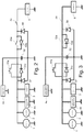
- the figure 2 shows a first mode of operation of the system according to the invention.
- the first elementary switch 51a is open
- the second elementary switch 51b is closed
- the third elementary switch 53a is open
- the electromechanical switch 54 is open.
- This mode of operation makes it possible to feed the main on-board networks 4a and 4b from the first storer 3.
- the figure 3 shows a second mode of operation of the system according to the invention.
- the first elementary switch 51a is open
- the second elementary switch 51b is driven in PWM
- the third elementary switch 53a is closed
- the electromechanical switch 54 is closed.
- This operating mode makes it possible to contribute to the BOOST function by exploiting the two storers 3, 6 with a limitation of the current supplied by the second storer 6 to the alternator-starter 1 so as to maintain a minimum voltage for the main on-board network 4a.
- This current limitation is obtained by controlling the second elementary switch 51b PWM driven by the supervisor 58 of the device 5, from a maximum current setpoint.
- the figure 4 represents four diagrams showing the evolution of different intensity and voltage measurements over time. The curves are divided into four diagrams for easy reading.
- a first curve (I_BOOST) represents the evolution of the input current of the alternator 1.
- a second curve (I_stacker 1) represents the evolution of the output current of the first storage unit 3.
- a third curve (lin_DCDC) represents the evolution current at the second terminal P1.
- a fourth curve (I_RDB) represents the evolution of the input current of the on-board network, in other words at the third terminal P2.
- a fifth curve (I_stacker2) represents the evolution of the output current of the second storage unit 6, in other words at the fourth terminal P3.
- a sixth curve (V_RDB) shows the evolution of the voltage at the edge network 4a.
- a seventh curve represents the evolution of intensity at the level of capacity 52.
- the main edge network 4a is fed exclusively by the first storer 3.
- the output current of the second storer 6 is substantially zero.
- the current at the second terminal P1 (lin_DCDC) is of the order of -20A).
- the output current of the first storage 3 is substantially equal to the input current of the main edge network 4a, of the order of 20A.
- the voltage at the level of the onboard network is of the order of 12v.
- the intensity at the level of the capacitor 52 is zero.
- the intensity at the alternator-starter gradually increases to 140A.
- the output intensity of the second storer 6 increases to about 100A.
- the intensity at the second terminal P1 is of the order of 80A.
- the output intensity of the first storer 3 is of the order of 60A.
- the input current of the main edge network 4a is always of the order of 20A.
- the inductive effects, generated by PWM control of the switch, cause voltage variations at the level of the on-board network (of the order of +/- 1V). These variations are relatively thanks to the capacity 52 which plays a role of filter and whose intensity varies between 40a and 40a
- the output current of the second storage unit 6 again becomes substantially zero.
- the current at the second terminal P1 also substantially becomes again of the order of -20A.
- the output current of the first storer 3 becomes gradually substantially equal to the input current of the main edge network 4a, of the order of 20A.
- the voltage at the level of the onboard network is of the order of 12v.
- the intensity at the level of the capacitance 52 becomes zero again.
- the input current of the main edge network 4a is always (before, during and after the activation of the BOOST) of the order of 20A. This is the desired effect: the operation of the onboard network is not affected by the activation of the BOOST.
- the figure 5 shows a third mode of operation of the system according to the invention. This is a refill of the second storer 6 with the application of a slope current directive to limit disturbances.
- the first elementary switch 51a is open, the second elementary switch 51b is controlled in OFF or in PWM.
- the third elementary switch 53a is driven in PWM.
- the electromechanical switch 54 is closed.
- the assembly comprising the first storage unit 3 and the alternator 1 supplies the main on-board network 4a and recharges the second storage unit 6.
- the figure 6 represents two diagrams, a first diagram showing the evolution of different voltage measurements over time and a second diagram showing the evolution of different intensity measurements over time.
- a first curve represents the evolution of the voltage at the main edge network 4a.
- a second curve represents the evolution of the voltage at the second storer 6.
- a third curve (I_Stocker1) represents the evolution of the current flowing through P1.
- a fourth curve (I_RDB) represents the evolution of the input current of the on-board network principal 4a.
- a fifth curve (I_stacker2) represents the evolution of the output current of the second storage unit 6.
- the main edge network 4a is fed exclusively by the first storer 3.
- the output current of the second storer 6 is substantially zero.
- the output current of the first storage 3 is substantially equal to the input current of the main edge network 4a, of the order of 20A.
- the voltage at the second storer 6 is 10V.
- the voltage at the on-board level is 14V.
- the intensity at the first storer gradually increases to 90A.
- the intensity at the second storer 6 increases to about 90A.
- the intensity at the main edge network 4a remains constant around 20A.
- the voltage at the second storage unit 6 remains around 10V (the charging current of the second storage unit 6 has reached the current limitation setpoint, therefore, there is a limitation of current, which is why it is around 10V ).
- the voltage at the on-board network remains around 14V "oscillating" by plus or minus 1V (without the filtering capacitor 52, there would be more oscillation.It is thanks to the capacitor 52 that the ripple is controlled) . This is the effect of the third PWM-controlled switch 53b which limits the charging current of the second storage unit 6.
- a third phase corresponding to the deactivation of the recharge of the second storer 6, the current at the second storer 6 becomes substantially zero again.
- the output current of the first storer 3 becomes gradually substantially equal to the input current of the main edge network 4a, of the order of 20A.
- the input current of the main edge network 4a is always (before, during and after activation of the recharge) of the order of 20A. This is the desired effect: the operation of the onboard network is not affected by the activation of the refill of the second storer 6.
- the voltage at the second storage 6 is 10V, which corresponds to a very unloaded storage.
- the voltage at the on-board level is 14V.
Description
L'invention concerne la gestion de l'énergie électrique d'un véhicule dans un réseau très basse tension (ou TBT), aussi appelé réseau 12V.The invention relates to the management of the electrical energy of a vehicle in a very low voltage network (or TBT), also called 12V network.
On connait, par le document
On connait aussi, par le document
L'invention a donc pour but de remédier aux inconvénients précités en proposant un dispositif de gestion de l'énergie amélioré, permettant de faire cohabiter deux stockeurs d'énergie sur un réseau et améliorant la sureté de fonctionnement du réseau électrique et la stabilité de la tension du réseau de bord.The invention therefore aims to overcome the aforementioned drawbacks by proposing an improved energy management device, allowing two energy storagers to coexist on a network and improving the reliability of operation of the electrical network and the stability of the power supply. on-board system voltage.
Elle propose plus précisément à cet effet un dispositif de gestion de transfert d'énergie comportant une première borne destinée à être reliée à une masse électrique, une deuxième borne destinée à être reliée à un premier stockeur d'énergie électrique, une troisième borne destinée à être reliée à au moins un consommateur électrique, une quatrième borne destinée à être reliée à un deuxième stockeur d'énergie électrique, caractérisé en ce qu'il comprend un premier interrupteur principal relié d'une part à la deuxième borne et d'autre part à la troisième borne, un deuxième interrupteur principal relié d'une part à la quatrième borne et d'autre part à la troisième borne, le premier interrupteur principal comportant une première diode dont la cathode est reliée à la troisième borne, le deuxième interrupteur principal comportant une deuxième diode dont la cathode est reliée à la troisième borne.It proposes more precisely for this purpose a power transfer management device comprising a first terminal intended to be connected to an electrical mass, a second terminal intended to be connected to a first storage of electrical energy, a third terminal intended to to be connected to at least one electrical consumer, a fourth terminal intended to be connected to a second storer of electrical energy, characterized in that it comprises a first main switch connected on the one hand to the second terminal and on the other hand at the third terminal, a second main switch connected firstly to the fourth terminal and secondly to the third terminal, the first main switch having a first diode whose cathode is connected to the third terminal, the second main switch; having a second diode whose cathode is connected to the third terminal.
Le terme « relié » indique que deux éléments sont reliés électriquement soit directement par une liaison électrique, soit indirectement par l'intermédiaire d'un ou plusieurs composant(s) (par exemple une inductance, une mesure (ou shunt) de courant ou un interrupteur).The term "connected" indicates that two elements are electrically connected either directly by an electrical connection, or indirectly via one or more components (eg an inductor, a current measurement or shunt) light switch).
L'expression « l'élément 1 est positionné entre l'élément 2 et l'élément 3 » indique que l'élément est relié électriquement à l'élément 2 et à l'élément soit directement par une liaison électrique, soit indirectement par l'intermédiaire d'un ou plusieurs composant(s) (par exemple une inductance, une mesure (ou shunt) de courant ou un interrupteur).The expression "the
L'utilisation d'interrupteurs à cathode commune (et non pas à anode commune comme dans le document
Selon une caractéristique de l'invention, le premier interrupteur principal comprend en outre un premier interrupteur élémentaire positionné entre la deuxième borne et la troisième borne.According to one characteristic of the invention, the first main switch further comprises a first elementary switch positioned between the second terminal and the third terminal.
Selon une caractéristique de l'invention, le premier interrupteur principal comporte, en outre, un deuxième interrupteur élémentaire, monté en parallèle de la première diode.According to a characteristic of the invention, the first main switch further comprises a second elementary switch, connected in parallel with the first diode.
Le deuxième interrupteur élémentaire permet de contrôler le passage du courant transitant depuis ou vers la deuxième borne.The second elementary switch controls the passage of the current flowing from or to the second terminal.
Selon une autre caractéristique de l'invention, le deuxième interrupteur principal comporte, en outre, un troisième interrupteur élémentaire, monté en parallèle de la deuxième diode.According to another characteristic of the invention, the second main switch further comprises a third elementary switch, connected in parallel with the second diode.
Le pilotage du troisième interrupteur élémentaire permet de contrôler le passage du courant transitant depuis ou vers la quatrième borne P3.The control of the third elementary switch makes it possible to control the passage of the current flowing from or to the fourth terminal P3.
De façon avantageuse, le dispositif de gestion de transfert d'énergie selon l'invention, comprend, en outre, un superviseur apte à délivrer :
- un signal modulé au deuxième interrupteur élémentaire de façon à limiter le courant transitant par ledit deuxième interrupteur élémentaire, ledit deuxième interrupteur élémentaire étant adapté pour être piloté par un signal en modulation de largeur d'impulsions, et
- un signal modulé au troisième interrupteur élémentaire de façon à limiter le courant transitant par ledit troisième interrupteur élémentaire, ledit troisième interrupteur élémentaire étant adapté pour être piloté par un signal en modulation de largeur d'impulsions.
- a modulated signal at the second elementary switch so as to limit the current flowing through said second elementary switch, said second elementary switch being adapted to be driven by a signal in pulse width modulation, and
- a modulated signal at the third elementary switch so as to limit the current flowing through said third elementary switch, said third elementary switch being adapted to be controlled by a signal in pulse width modulation.
Le pilotage du deuxième interrupteur élémentaire permet une limitation de courant transitant depuis la quatrième borne P3 vers la première borne P1 (par exemple pour alimenter une machine électrique branchée sur P1) pour respecter les contraintes en tension du réseau de bord. Cette limitation est monodirectionnelle. En limitant le courant sortant par la deuxième borne P1, on peut garantir une tension minimale aux équipements reliés à la troisième borne P2.The control of the second elementary switch allows a limitation of current flowing from the fourth terminal P3 to the first terminal P1 (for example to power an electrical machine connected to P1) to meet the voltage constraints of the on-board network. This limitation is monodirectional. By limiting the outgoing current by the second terminal P1, it is possible to guarantee a minimum voltage to the equipment connected to the third terminal P2.
Le pilotage du troisième interrupteur élémentaire permet une limitation de courant transitant depuis la première borne P1 vers la quatrième borne P3 (par exemple pour recharger le deuxième stockeur à partir de l'ensemble comprenant le premier stockeur et l'alternateur) tout en gardant une tension respectant les contraintes en tension du réseau de bord. Cette limitation est monodirectionnelle. Cette maîtrise du courant de recharge du stockeur garantit un niveau de tension conforme aux critères de qualité du réseau de bord.The control of the third elementary switch allows a limitation of current flowing from the first terminal P1 to the fourth terminal P3 (for example to recharge the second storage unit from the assembly comprising the first storage unit and the alternator) while keeping a voltage respecting the voltage constraints of the on-board network. This limitation is monodirectional. This control of the charging current of the storage unit guarantees a level of voltage that complies with the quality criteria of the on-board electrical system.
De façon avantageuse, le dispositif de gestion de transfert d'énergie selon l'invention, comprend, en outre,
- une première diode de roue libre dont l'anode est reliée à la première borne et la cathode à l'anode de la deuxième diode,
- une deuxième diode de roue libre dont l'anode est reliée à la première borne et la cathode à l'anode de la première diode et
- une capacité reliée d'une part à la troisième borne et d'autre part à la première borne.
- a first freewheeling diode whose anode is connected to the first terminal and the cathode to the anode of the second diode,
- a second freewheel diode whose anode is connected to the first terminal and the cathode to the anode of the first diode and
- a capacitor connected on the one hand to the third terminal and on the other hand to the first terminal.
La capacité permet de filtrer la tension du réseau de bord : limiter les variations de tension induite par les pilotages en PWM des interrupteurs principaux. Sans cela, du fait des effets inductifs, la tension peut atteindre des niveaux très élevés. Les diodes de roues libres permettent aussi d'éviter des surtensions.The capacity makes it possible to filter the voltage of the on-board network: to limit the variations of voltage induced by the PWM controls of the main switches. Without this, because of the inductive effects, the voltage can reach very high levels. The freewheel diodes also help to prevent overvoltages.
Avantageusement, le dispositif de gestion de transfert d'énergie selon l'invention, comprend, en outre, un interrupteur électromécanique positionné entre d'une part, la quatrième borne et d'autre part, un ensemble comprenant l'anode de la deuxième diode et la cathode de la première diode de roue libre. L'interrupteur électromécanique, en position ouverte, permet d'isoler le deuxième stockeur par exemple en cas d'atteinte aux limites du stockeur. Il est également ouvert lors de la veille du véhicule.Advantageously, the energy transfer management device according to the invention further comprises an electromechanical switch positioned between, on the one hand, the fourth terminal and, on the other hand, an assembly comprising the anode of the second diode. and the cathode of the first freewheeling diode. The electromechanical switch in the open position makes it possible to isolate the second storage unit, for example if the storage limits are reached. It is also open when the vehicle is awake.
Avantageusement, le dispositif de gestion de transfert d'énergie selon l'invention, comprend, en outre :
- une première inductance positionnée entre, d'une part, la deuxième borne et, d'autre part, l'ensemble comprenant l'anode de la première diode et la cathode de la deuxième diode de roue libre, et
- une deuxième inductance positionnée entre d'une part, la quatrième borne et, d'autre part, l'ensemble comprenant l'anode de la deuxième diode et la cathode de la première diode de roue libre.
- a first inductor positioned between, on the one hand, the second terminal and, on the other hand, the assembly comprising the anode of the first diode and the cathode of the second free-wheeling diode, and
- a second inductor positioned between, on the one hand, the fourth terminal and, on the other hand, the assembly comprising the anode of the second diode and the cathode of the first freewheeling diode.
Ces deux inductances sont ajoutées pour compenser un effet inductif insuffisant des faisceaux. Ce phénomène peut se produire notamment si les faisceaux sont relativement courts (quelques centimètres).These two inductances are added to compensate for an insufficient inductive effect of the beams. This phenomenon can occur especially if the beams are relatively short (a few centimeters).
L'invention concerne un système électrique d'un véhicule comportant un producteur d'énergie un premier stockeur d'énergie, un deuxième stockeur d'énergie et un réseau de bord principal comportant au moins un consommateur électrique caractérisé en ce qu'il comporte en outre un dispositif de gestion de transfert d'énergie selon l'invention, la deuxième borne étant reliée au premier stockeur, la troisième borne étant reliée au réseau de bord, la quatrième borne étant reliée au deuxième stockeur, la première borne étant relié à une masse électrique du véhicule, le producteur d'énergie étant relié à la deuxième borne ou à la troisième borne.The invention relates to an electrical system of a vehicle comprising an energy producer a first energy store, a second energy store and a main edge network comprising at least one electrical consumer characterized in that it comprises in in addition to a power transfer management device according to the invention, the second terminal being connected to the first storage unit, the third terminal being connected to the on-board network, the fourth terminal being connected to the second storage unit, the first terminal being connected to a electric mass of the vehicle, the energy producer being connected to the second terminal or the third terminal.
L'invention concerne aussi un véhicule comportant un dispositif de gestion de transfert d'énergie selon l'invention ou un système électrique selon l'invention.The invention also relates to a vehicle comprising a power transfer management device according to the invention or an electrical system according to the invention.
D'autres caractéristiques et avantages de l'invention apparaîtront à l'examen de la description détaillée ci-après, et des dessins annexés, sur lesquels:
- la
figure 1 illustre un système électrique selon l'invention ; - la
figure 2 illustre un premier mode de fonctionnement du système selon l'invention ; - la
figure 3 illustre un deuxième mode de fonctionnement du système selon l'invention ; - la
figure 4 représente deux diagrammes présentant l'évolution, au cours du temps, de différentes d'intensités mesurées dans le système selon l'invention. - la
figure 5 illustre un troisième mode de fonctionnement du système selon l'invention ; - la
figure 6 représente deux diagrammes présentant l'évolution, au cours du temps, de différentes d'intensités et tensions mesurées dans le système selon l'invention ; - la
figure 7 montre une variante de réalisation d'un système électrique selon l'invention. - La
figure 8 montre un mode de réalisation simplifié d'un système électrique selon l'invention.
- the
figure 1 illustrates an electrical system according to the invention; - the
figure 2 illustrates a first mode of operation of the system according to the invention; - the
figure 3 illustrates a second mode of operation of the system according to the invention; - the
figure 4 represents two diagrams showing the evolution, over time, of different intensities measured in the system according to the invention. - the
figure 5 illustrates a third mode of operation of the system according to the invention; - the
figure 6 represents two diagrams showing the evolution over time of different intensities and voltages measured in the system according to the invention; - the
figure 7 shows an alternative embodiment of an electrical system according to the invention. - The
figure 8 shows a simplified embodiment of an electrical system according to the invention.
Les dessins annexés pourront non seulement servir à compléter l'invention, mais aussi contribuer à sa définition, le cas échéant.The attached drawings may not only serve to complete the invention, but also contribute to its definition, if any.
Dans ce qui suit, on considère à titre d'exemple non limitatif que le système électrique présenté est embarqué à bord d'un véhicule comportant un moteur thermique comportant un réseau de bord comprenant des consommateurs.In what follows, it is considered by way of non-limiting example that the electrical system presented is embedded in a vehicle comprising a heat engine having an edge network comprising consumers.
Mais l'invention n'est pas limitée à ce mode de réalisation. En effet, elle concerne tout système électrique et électronique comportant au moins deux stockeurs d'énergie et un consommateur.But the invention is not limited to this embodiment. Indeed, it relates to any electrical and electronic system comprising at least two energy storage and a consumer.
En référence à la
Le dispositif de gestion de transfert d'énergie électrique 5 comporte quatre bornes : d'une part, une première borne M, qui est une borne négative connectée à une masse du véhicule, et d'autre part, une deuxième borne P1, une troisième borne P2 et une quatrième borne P3 qui sont des bornes positives.The electrical energy transfer management device 5 comprises four terminals: firstly, a first terminal M, which is a negative terminal connected to a vehicle ground, and secondly, a second terminal P1, a third terminal terminal P2 and a fourth terminal P3 which are positive terminals.
Le producteur d'énergie électrique 1 est relié électriquement d'un côté à la deuxième borne P1 du dispositif 5, avec un faisceau électrique (résistif et inductif), et de l'autre côté à la masse. L'alternateur 2 est aussi relié électriquement d'un côté à la deuxième borne P1 du dispositif 5, avec un faisceau électrique (résistif et inductif), et de l'autre côté à la masse. Le réseau de bord secondaire 4b est aussi relié électriquement d'un côté à la deuxième borne P1 du dispositif 5, avec un faisceau électrique (résistif et inductif), et de l'autre côté à la masse. Le premier stockeur d'énergie électrique 3 est aussi relié électriquement d'un côté à la deuxième borne P1 du dispositif 5 et de l'autre côté à la masse.The
Le réseau de bord principal 4a est relié électriquement d'un côté à la troisième borne P2 du dispositif 5 avec au moins un faisceau et de l'autre côté à la masse.The
Le deuxième stockeur 6 est relié électriquement d'un côté à la quatrième borne P3 du dispositif 5 et de l'autre côté à la masse avec des faisceaux.The
L'alternateur 1 (ou alterno-démarreur) est utilisé pour la fourniture de puissance électrique au réseau de bord 4a, 4b du véhicule, pour les redémarrages du moteur thermique et pour les phases dite de BOOST. Lors d'une phase de BOOST, l'alternateur est utilisé pour une fournir du couple au moteur thermique en phase de roulage. En phase de BOOST, l'alternateur devient donc consommateur de courant.The alternator 1 (or alternator-starter) is used for the supply of electrical power to the vehicle
Le démarreur 2 est utilisé pour les premiers démarrages du véhicule et éventuellement, selon la configuration du véhicule, pour les redémarrages du véhicule.The
Le premier stockeur d'énergie électrique 3, par exemple de type batterie plomb 12V, est utilisé notamment pour le démarrage et le redémarrage, pour l'alimentation des consommateurs du réseau de bord principal 4a et secondaire 4b pendant les phases de veille du véhicule.The first
Le véhicule comporte aussi un capteur 8 collectant des données relatives au premier stockeur 3 : le courant du premier stockeur 3, la tension du premier stockeur 3, la température du premier stockeur 3, une estimation de l'état de charge du premier stockeur 3. De façon alternative, si le premier stockeur 3 est instrumenté (mesure de courant et de tension), il est possible d'exploiter ces informations.The vehicle also comprises a
Le réseau de bord principal 4a inclut des éléments électriques du véhicule tels que des calculateurs et des équipements électriques, par exemple, des équipements de confort, les organes sécuritaires ainsi que les autres équipements électriques n'entrant pas dans les catégories précédemment citées.The main
De façon optionnelle, le véhicule comporte un réseau de bord secondaire 4b comportant uniquement des consommateurs (ou organes) qui ne sont pas perturbés pendant les phases de démarrage, de redémarrage et de BOOST.Optionally, the vehicle comprises a
Le deuxième stockeur 6 (ou stockeur secondaire), par exemple une batterie lithium-ion, est utilisé pour alimenter le réseau de bord principal 4a pendant l'usage du véhicule (hors veille).The second storer 6 (or secondary storer), for example a lithium-ion battery, is used to feed the main on-
Le véhicule comporte aussi un superviseur 7 apte à collecter et transmettre des données du véhicule.The vehicle also includes a supervisor 7 capable of collecting and transmitting data from the vehicle.
Le véhicule comporte aussi un capteur 8 collectant des données relatives au premier stockeur 3 : le courant du premier stockeur 3, la tension du premier stockeur 3, la température du deuxième stockeur 3, une estimation de l'état de charge du deuxième stockeur 3.The vehicle also comprises a
Le véhicule comporte aussi des éléments de distribution électrique 10, 11, 12. Ces éléments de distribution électrique 10, 11, 12 sont par exemple des faisceaux ayant des caractéristiques inductive et résistive. Les faisceaux contribue au bon fonctionnement du système grâce à leur caractéristique résistive et inductive.The vehicle also comprises
Selon une variante de réalisation de l'invention, le dispositif 5 comporte en outre des inductances (R,L) de l'ordre de quelques µH (par exemple inférieure à 10µH) dans le cas où l'effet inductif des faisceaux n'est pas suffisant lors du pilotage des interrupteurs en PWM. Une telle variante est présentée à la
Comme expliqué précédemment, le dispositif 5 comporte quatre bornes :
- la première borne M, borne négative connectée à une masse du véhicule,
- la deuxième borne P1, borne positive connectée au
premier stockeur 3, au démarreur 2 et à l'alternateur 1 et au réseau de bordsecondaire 4b ; - la troisième borne P2, borne positive connectée au réseau de bord principal 4a ;
- la quatrième borne P3, borne positive connectée au deuxième stockeur 6.
- the first terminal M, negative terminal connected to a mass of the vehicle,
- the second terminal P1, a positive terminal connected to the
first storage unit 3, thestarter 2 and thealternator 1 and thesecondary edge network 4b; - the third terminal P2, positive terminal connected to the
main edge network 4a; - the fourth terminal P3, a positive terminal connected to the
second storage unit 6.
Le dispositif 5 comporte deux interrupteurs principaux 51,53, aussi appelé interrupteurs de puissance, (par exemple de type MOSFET, acronyme anglais de Metal Oxide Semiconductor Field Effect Transistor - qui se traduit par transistor à effet de champ à structure métal-oxyde-semiconducteur) :
Le premier interrupteur principal 51 est composé d'un premier interrupteur élémentaire 51a, d'un deuxième interrupteur élémentaire 51b et d'une première diode 51c.The device 5 comprises two
The first
Il peut y avoir plusieurs deuxièmes interrupteurs élémentaires 51b et diodes 51c montés en parallèles. Dans ce cas, les deuxièmes interrupteurs élémentaires 51b sont commandés simultanément.There may be several second
La première diode 51c est mise en place pour la sûreté de fonctionnement. En effet la première diode 51c permet d'alimenter le réseau de bord principal 4a s'il y a une défaillance en circuit ouvert du deuxième interrupteur élémentaire 51b, 53, et/ou 54 A confirmer. En effet, si le système est dans une phase de décharge du second stockeur 6 dans le réseau de bord princpal 4a et que le deuxième interrupteur principal 53 et/ou l'interrupteur électromécanique 54 deviennent hors service ouvert, alors comme le premier interrupteur élémentaire 51a et le deuxième interrupteur 51b sont pilotés ouverts, le courant passera par la première diode 51c pour alimenter le réseau de bord principal 4a.The
Le premier interrupteur élémentaire (par exemple un interrupteur de type électromécanique) 51a est normalement fermé. Il est utilisé pour alimenter le véhicule pendant une phase parking du véhicule (veille du véhicule).The first elementary switch (for example an electromechanical type switch) 51a is normally closed. It is used to power the vehicle during a parking phase of the vehicle (vehicle standby).
Le deuxième interrupteur élémentaire 51b fonctionne :
- en ON (fermeture manuelle) : Dans ce mode de pilotage, il n'y a pas de limitation du courant quel que soit le sens du courant ;
- En OFF (ouverture manuelle) : pas de passage de courant dans le premier interrupteur
principal 51 dans le sens du deuxième stockeur 6 vers lepremier stockeur 3 lorsque le premier interrupteur élémentaire 51a ouvert. Par contre, si le deuxième interrupteur élémentaire 51b est de type MOSFET, il y a une possibilité du passage de courant dans le sens dupremier stockeur 3 vers le deuxième stockeur 6, ce courant passerait par la diode du MOS (ou diode 51c) si U55_a > U_55b + Vd avec Vd tension de la diode l'état passant, U55_a la tension dupremier stockeur 3 entre la deuxième borne P1 et la première borne M et U55b la tension du réseau de bord principal 4a entre la troisième borne P2 et la deuxième borne M. - En PWM (commande piloté / mode automatique) dans le sens deuxième stockeur 6 vers
premier stockeur 3 de façon à limiter la décharge du deuxième stockeur 6 vers lepremier stockeur 3. Cette limitation est obtenue à partir d'une consigne de courant et/ou de tension à respecter Dans le mode PWM, il n'y a pas de limitation de courant dans le sens stockeur 3 vers l'ensemble stockeur 6 et réseau de bord 4a, nous sommes dans un fonctionnement similaire au mode ON puisque le courant est inférieur à la consigne de courant.
- ON (manual closing): In this control mode, there is no current limitation whatever the direction of the current;
- In OFF (manual opening): no passage of current in the first
main switch 51 in the direction of thesecond storer 6 to thefirst storer 3 when the firstelementary switch 51a open. On the other hand, if the secondelementary switch 51b is of the MOSFET type, there is a possibility of the passage of current in the direction of thefirst storer 3 to thesecond storer 6, this current would pass through the diode of the MOS (ordiode 51c) if U55_a> U_55b + Vd with Vd diode voltage in the on state, U55_a the voltage of thefirst storage 3 between the second terminal P1 and the first terminal M and U55b the voltage of themain edge network 4a between the third terminal P2 and the second terminal M. - In PWM (controlled control / automatic mode) in the
second storage direction 6 tofirst storer 3 so as to limit the discharge of thesecond storer 6 to thefirst storer 3. This limitation is obtained from a current and / or voltage setpoint to be respected In the PWM mode, it is There is no current limitation in thestorage direction 3 to thestorage unit 6 and thenetwork 4a, we are in a similar operation to the ON mode since the current is lower than the current setpoint.
Le deuxième interrupteur élémentaire 51b est pilotable en tension et en courant dans le transfert d'énergie électrique (à partir de consigne de tension et de courant pour la construction du signal PWM). Tant que le courant, la tension et la puissance sont dans un gabarit défini par des valeurs de limitation, il n'y a pas d'écrêtage en tension, de limitation du courant ou de limitation de la puissance et le deuxième interrupteur élémentaire 51b se comporte comme un interrupteur fermé. Si le courant, la tension ou la puissance est au-delà du gabarit défini, il y a un écrêtage en tension, ou une limitation en courant ou une limitation de la puissance et le deuxième interrupteur élémentaire 51b se comporte comme un hâcheur monodirectionnel.The second
Le pilotage de 51b permet une mise en place d'une limitation de courant dans le sens du deuxième stockeur 6 vers l'ensemble comprenant le premier stockeur 3 et l'alterno-démarreur 1 sous contrainte de tension du réseau de bord principal 4a (de façon à maintenir un tension minimale dans le réseau de bord principal 4a). Cette limitation de courant est utilisée pour contribuer à la fonction BOOST et fournir du courant à l'alterno-démarreur 1 qui contribue alors à fournir de couple au moteur thermique en phase de roulage véhicule.The control of 51b makes it possible to set up a current limitation in the direction of the
Le pilotage de 51b ne permet pas de limitation du courant dans le sens du premier stockeur 3 vers le deuxième stockeur 6 notamment à cause de la première diode.The
Le deuxième interrupteur 51b peut être piloté :
- de façon manuelle, à partir d'une consigne de courant de décharge (de 0 à Imax);
- de façon automatique, sous autorisation : dès que la tension du
premier stockeur 3 passe sous un seuil de tension prédéterminé, le superviseur autorise de la décharge du deuxième stockeur 6 vers l'ensemble comprenant lepremier stockeur 3 et l'alterno-démarreur 1 sous la contrainte d'une consigne de courant maximal Imax de décharge et avec le respect d'une tension minimale du réseau de bord principal 4a.
- manually, from a discharge current setpoint (from 0 to Imax);
- automatically, under authorization: as soon as the voltage of the
first storer 3 passes below a predetermined voltage threshold, the supervisor authorizes the discharge of thesecond storer 6 to the assembly comprising thefirst storer 3 and the alternator-starter 1 under the constraint of a discharge current maximum Imax and with the respect of a minimum voltage of themain edge network 4a.
Le deuxième interrupteur principal 53 comporte un troisième interrupteur 53a et une deuxième diode 53b.The second
Il peut y en avoir plusieurs interrupteurs principaux 53 en parallèle. Les troisièmes interrupteurs élémentaires 53a sont alors commandés simultanément.There can be several
Le troisième interrupteur 53a fonctionne :
- en ON (fermeture « manuelle ») : Dans ce sens, il n'y a pas de limitation du courant quel que soit le sens du courant ;
- en OFF (ouverture « manuelle ») : pas de passage de courant dans 53a dans le sens stockeur 3
vers stockeur 6. Par contre,si 53a est de type MOSFET, il y a une possibilité du passage de courant dans le sens stockeur 6 vers stockeur 3, ce courant passerait par la diode du MOS (ou diode 53b) si U55_c > U_55b + Vd avec Vd tension de la diode à l'état passant. - en PWM (commande piloté / mode automatique) dans le sens de l'ensemble comprenant le
premier stockeur 3 et le générateur 1 vers le deuxième stockeur 6, de façon à limiter la recharge dupremier stockeur 6. Cette limitation est obtenue à partir d'une consigne de courant et/ou de tension à respecter Dans le mode PWM, il n'y a pas de limitation de courant dans le sens stockeur 6 vers l'ensemble stockeur 3/réseau de bordsecondaire 4b et réseau de bord principal 4a, nous sommes dans un fonctionnement similaire au mode ON puisque le courant est inférieur à la consigne de courant.
- ON ("manual" closing): In this sense, there is no current limitation regardless of the current direction;
- in OFF ("manual" opening): no passage of current in 53a in the
storage direction 3 tostorage 6. On the other hand, if 53a is of MOSFET type, there is a possibility of the current flow in thestorage direction 6 toStorer 3, this current would pass through the diode of the MOS (ordiode 53b) if U55_c> U_55b + Vd with Vd voltage of the diode in the on state. - in PWM (piloted control / automatic mode) in the direction of the assembly comprising the
first storer 3 and thegenerator 1 to thesecond storer 6, so as to limit the recharge of thefirst storer 6. This limitation is obtained from a current and / or voltage setpoint to be respected In the PWM mode, there is no current limitation in thestorage direction 6 to thestorage unit 3 /secondary edge network 4b andmain edge network 4a, we are in a mode similar to the ON mode since the current is lower than the current setpoint.
Le troisième interrupteur 53a est pilotable en tension et en courant dans le transfert d'énergie électrique (à partir de consigne en tension et en courant pour la construction du PWM). Tant que le courant, la tension et la puissance sont dans un gabarit défini par des valeurs de limitation, il n'y a pas d'écrêtage en tension, de limitation du courant ou de limitation de la puissance et le troisième interrupteur 53a se comporte comme un interrupteur fermé. Si le courant, la tension ou la puissance est au-delà du gabarit défini, il y a un écrêtage en tension, ou une limitation en courant ou une limitation de la puissance et le troisième interrupteur 53a se comporte comme un hâcheur monodirectionnel.The
Le pilotage du troisième interrupteur 53a permet la mise en place d'une limitation de courant dans le sens de l'ensemble comprenant le premier stockeur 3 le démarreur 1 et l'alternateur 2 vers le deuxième stockeur 6 sous contraintes :
- D'une consigne en courant de recharge maximal du deuxième stockeur 6 ;
- D'une tension réseau de bord principal 4a minimale à garantir ;
- D'une tension maximale admissible du deuxième stockeur 6.
- A maximum charging current setpoint of the
second storage unit 6; - A minimum main
trunk network voltage 4a to be guaranteed; - Maximum permissible voltage of the
second storage unit 6.
Le pilotage du troisième interrupteur 53a ne permet pas de limitation du courant dans le sens du deuxième stockeur 6 vers l'ensemble comprenant le premier stockeur 3 le démarreur 1 et l'alternateur 2.The control of the
La deuxième diode 53b est mise en place pour la sûreté de fonctionnement. La deuxième diode 53b permet d'alimenter le réseau de bord principal 4a s'il y a une défaillance en circuit ouvert de [51b], [53a] et [51c].The
En résumé, le deuxième interrupteur élémentaire 51b et le troisième interrupteur élémentaire 53a se comporte chacun comme un hacheur monodirectionnel. En revanche, le dispositif 5, au global, se comporte comme un abaisseur bidirectionnel.In summary, the second
Le dispositif selon l'invention 5 comporte aussi un interrupteur électromécanique 54 normalement ouvert permettant une isolation du deuxième stockeur 6 par exemple en cas d'atteinte des conditions aux limites du deuxième stockeur 6 (durabilité du stockeur) Il est également ouvert lorsque le véhicule est en veille : la batterie lithium n'est pas utilisée pendant la veille du véhicule ou d'une défaillance de l'interrupteur principal 53 à l'état fermé (toujours passant).The device according to the invention also comprises a normally open
L'invention comporte aussi une capacité de filtrage 52 relié d'une part à la troisième borne P2 et la première borne M. La capacité permet de filtrer la tension du réseau de bord principal 4a et ainsi de limiter les variations de tension induite par les pilotages en PWM des interrupteurs principaux 51,53. Sans cela, du fait des effets inductifs, la tension peut atteindre des niveaux très élevés (liés à U=L*dl/dt avec un dt très faible on obtient un U très élevé).The invention also comprises a
Les interrupteurs principaux 51 et 53 ont un positionnement non conventionnel dans une architecture électrique d'un véhicule. Les diodes sont à cathode commune avec tout ou partie du réseau de bord 4a électrique 12V connecté à ces cathodes. Autrement dit, le réseau de bord principal est connecté aux cathodes des diodes 51c, 53c.The main switches 51 and 53 have an unconventional positioning in an electrical architecture of a vehicle. The diodes are common cathode with all or part of the 12V electrical network 12a connected to these cathodes. In other words, the main edge network is connected to the cathodes of the
Le positionnement des interrupteurs principaux 51, 53 et des diodes 51c, 53b permet de s'assurer que le réseau de bord principal 4a peut être alimenté quel que soit le mode de pilotage des interrupteurs élémentaires 51a, 51b, 53b grâce aux diodes 51c, 53c.The positioning of the
Le dispositif 5 permet, en pilotant les interrupteurs principaux 51, 53, d'alimenter les consommateurs du réseau de bord 4a et 4b avec différentes sources d'énergie :
- Soit à partir de l'alternateur 1 avec une consigne de tension pouvant varier de 13 à 16V;
- Soit à partir de l'ensemble
premier stockeur 3, alternateur 1 par une gestion des interrupteurs principaux 51, 53. - Soit à partir du deuxième stockeur 6 par une gestion des interrupteurs principaux 51, 53.
- Either from the
alternator 1 with a voltage setpoint that can vary from 13 to 16V; - Either from the
first storage set 3,alternator 1 by a management of themain switches - Either from the
second storer 6 by a management of themain switches
Le dispositif selon l'invention comporte aussi deux mesures de courant 50a, 50b :
- Une première mesure de
courant 50a mesurant le courant passant par le deuxième interrupteur élémentaire 51b et la premièrediode 51c (le courant passant par le premier interrupteur élémentaire 51a n'est pas mesuré par la première decourant 50a) et qui est utilisée notamment pour la mesure de courant de recharge du premier stockeur 3 par le deuxième stockeur 6 ou pour l'aide au démarrage/ redémarrage par une fourniture de courant limité du deuxième stockeur 6 pour l'alternateur 1ou le démarreur 2. - Une deuxième mesure de
courant 50b mesurant la recharge du deuxième stockeur 6.
- A first
current measurement 50a measuring the current passing through the secondelementary switch 51b and thefirst diode 51c (the current passing through the firstelementary switch 51a is not measured by the current first 50a) and which is used in particular for measuring the charging current of thefirst storage unit 3 by thesecond storage unit 6 or for the start / restart aid by a limited current supply of thesecond storage unit 6 foralternator 1 orstarter 2. - A second
current measurement 50b measuring the recharge of thesecond storer 6.
L'invention comporte aussi trois mesures de tensions 55a, 55b, 55c.The invention also comprises three
La première mesure de tension 55a mesure la tension du premier stockeur 3 entre la deuxième borne P1 et la première borne M.The
La deuxième mesure de tension 55b mesure la tension du réseau de bord principal 4a entre la troisième borne P2 et la deuxième borne M.The
La troisième mesure de tension 55c mesure la différence de potentiel entre, d'une part, le premier interrupteur principal 53 et l'interrupteur électromécanique 54 (potentiel positif) et, d'autre part, la borne M (potentiel négatif).The third voltage measurement 55c measures the potential difference between, on the one hand, the first
Le dispositif selon l'invention 5 comporte aussi deux diodes de roue libre 56, 57.The device according to the invention 5 also comprises two
La première diode de roue libre 56 est indispensable lors du fonctionnement en PWM, sinon la tension devient trop élevée sur le deuxième stockeur 6, en raison des effets inductifs.The first
La deuxième diode de roue libre 57 est indispensable lors du fonctionnement en PWM, sinon la tension devient trop élevée sur le premier stockeur 3 (hors démarrage, redémarrage). Sans diode, les surtensions peuvent détruire les interrupteurs
Si les interrupteurs élémentaires 51b, 53a ne sont pas pilotés en PWM, les diodes de roue libres 56, 57 ne sont pas obligatoires. En effet l'architecture selon l'invention permet de travailler en PWM (avec diodes) ou sans PWM (sans diode).The second
If the
En particulier, si le deuxième interrupteur élémentaire 51b est piloté en ouvert / fermé (ON/OFF) et le troisième interrupteur élémentaire 53a est piloté en PWM la deuxième diode de roue libre 57 n'est obligatoire. La
Le dispositif selon l'invention 5 comporte aussi un superviseur 58. Le superviseur 58 est configuré pour générer un signal de pilotage C1, C2, correspondant au mode de fonctionnement déterminé, pour le deuxième interrupteur élémentaire 51b et le troisième interrupteur élémentaire 53a. Ces signaux de pilotage permettent d'ouvrir et de fermer les interrupteurs 51b, 53a afin de réguler les valeurs de la tension et du courant associées au transfert d'énergie lorsqu'une limitation du courant et/ou de la tension est nécessaire.The device according to the invention 5 also comprises a
La variante de réalisation de la
- une première inductance L1 positionnée entre, d'une part, la deuxième borne P1 et, d'autre part, l'ensemble comprenant l'anode de la première
diode 51c et la cathode de la deuxième diode de rouelibre 57, et - une deuxième inductance L2 positionnée entre d'une part, la quatrième borne P3 et, d'autre part, l'ensemble comprenant l'anode de la deuxième
diode 53b et la cathode de la première diode de rouelibre 56.
- a first inductor L1 positioned between, on the one hand, the second terminal P1 and, on the other hand, the assembly comprising the anode of the
first diode 51c and the cathode of the second free-wheelingdiode 57, and - a second inductor L2 positioned between, on the one hand, the fourth terminal P3 and, on the other hand, the assembly comprising the anode of the
second diode 53b and the cathode of the firstfreewheeling diode 56.
Les différents éléments de l'architecture de la
L'alternateur 1 communique [a] avec le superviseur véhicule 7. L'alternateur 1 envoie au superviseur véhicule 7 des données alternateur avec par exemple la charge de l'alternateur. Le superviseur véhicule 7 envoie vers l'alternateur 1 des consignes de pilotage de l'alternateur.The
Le réseau de bord principal 4a envoie [b] au superviseur véhicule 7 des informations concernant l'état des consommateurs électriques présents sur le réseau de bord principal 4a. Plus précisément, ce sont certains constituants (des consommateurs) du réseau de bord principal 4a qui envoient des informations au superviseur 7. Cette information permet au superviseur véhicule 7 de déterminer une plage de fonctionnement nominale en tension du réseau de bord principal 4a en définissant une tension minimale (Umin) et une tension maximale (Umax) à garantir.The main on-
Le réseau de bord secondaire 4b envoie [c] au superviseur véhicule 7 des informations concernant l'état des consommateurs électriques présents sur le réseau de bord secondaire 4b. Plus précisément, ce sont certains constituants (des consommateurs) du réseau de bord secondaire 4b qui envoient des informations au superviseur 7. Cette information permet au superviseur véhicule 7 de déterminer une plage de fonctionnement nominale en tension du réseau de bord secondaire 4b en définissant une tension minimale (Umin) et une tension maximale (Umax) à garantir.The
Le premier stockeur communique [d] au superviseur véhicule 7 des informations concernant le premier stockeur 3, a minima : la température du premier stockeur, le courant du premier stockeur, la tension du premier stockeur, estimation de l'état de charge du premier stockeur.The first storer communicates [d] to the vehicle supervisor 7 information concerning the
Le superviseur du dispositif 5 reçoit [e] la première mesure de tension 55a entre P1 et M. Cette mesure représente la tension du premier stockeur 3 (c'est une image à la chute de tension prêt).The supervisor of the device 5 receives [e] the
Le superviseur 58 du dispositif 5 reçoit [f] la première mesure de courant 50a dans le sens réseau de bord principale 4a vers premier stockeur 3 sur la deuxième borne P1 du dispositif 5.The
Le superviseur 58 du dispositif 5 pilote [g] le premier interrupteur élémentaire 51a.The
Le superviseur 58 du dispositif 5 pilote aussi [h] le deuxième interrupteur élémentaire 51b. Il s'agit d'un pilotage de type ON (autrement dit, en mode passant bidirectionnel), OFF (autrement dit, bloqué dans le sens réseau de bord secondaire 4b vers réseau de bord principal 4a et peut être passant dans le sens du premier stockeur 3 vers réseau de bord principal 4a à travers la première diode 51c ou en commutation (PWM) en mode limitation de courant dans le sens du deuxième stockeur 6 vers le premier stockeur 3 et passant dans le sens stockeur 3 vers réseau de bord 4a.The
Le superviseur 58 du dispositif 5 reçoit [i] la deuxième mesure de tension entre P2 et M. Cette mesure représente la tension du réseau de bord principal 4a.The
Le superviseur 58 du dispositif 5 pilote [j] le troisième interrupteur élémentaire 53a. Il s'agit d'un pilotage de type ON (autrement dit, passant quel que soit le sens du courant et la valeur du courant), OFF ou en commutation (PWM) en mode limitation de courant de recharge du deuxième stockeur 6 dans le sens alternateur 1 vers deuxième stockeur 6.The
Le superviseur 58 du dispositif 5 pilote aussi [k] l'interrupteur électromécanique 54.The
Le superviseur 58 du dispositif 5 reçoit [l] la deuxième mesure de courant 50b du deuxième stockeur 6.The
Le superviseur 58 du dispositif 5 reçoit [m] la troisième mesure de tension 55c Cette mesure représente la tension du deuxième stockeur 6.The
Le superviseur véhicule 7 et le superviseur 58 du dispositif 5 échangent [n] des informations.The vehicle supervisor 7 and the
Le superviseur véhicule 7 demande au superviseur 58 du dispositif 5 une contribution au mode BOOST.The vehicle supervisor 7 requests the
Le superviseur véhicule 7 envoie au superviseur 58 du dispositif 5 :
- une consigne de courant maximal de recharge du deuxième stockeur 6 et une tension maximale du deuxième stockeur 6 (qui peut évoluer en fonction, par exemple, de la température du stockeur) pour le pilotage du troisième interrupteur élémentaire 53a en PWM ;
- une consigne de courant maximal de décharge du deuxième stockeur 6 vers l'alternateur 1, le démarreur 2 et le premier stockeur 3 (et réseau de bord
secondaire 4b lorsqu'il est présent), pour le pilotage du deuxième interrupteur élémentaire 51b en PWM. - une consigne ON/OFF pour le pilotage du premier interrupteur élémentaire 51a ;
- une consigne ON/OFF pour le pilotage de l'interrupteur électromécanique 54.
- a maximum charging current setpoint of the
second storage unit 6 and a maximum voltage of the second storage unit 6 (which can change as a function of, for example, the storage temperature) for controlling the thirdelementary switch 53a in PWM; - a maximum discharge current setpoint of the
second storer 6 to thealternator 1, thestarter 2 and the first storer 3 (andsecondary edge network 4b when present), for controlling the secondelementary switch 51b in PWM. - an ON / OFF instruction for controlling the first
elementary switch 51a; - an ON / OFF instruction for controlling the
electromechanical switch 54.
Le superviseur du dispositif 58 envoie au superviseur véhicule 7 des informations de diagnostic du système : par exemple des états des interrupteurs. Cela permet de définir le mode de pilotage adapté. S'il y a un interrupteur hors service : on passe à un mode dégradé.The supervisor of the
Le deuxième stockeur communique [o] au superviseur véhicule 7 des informations concernant le deuxième stockeur 6, par exemple : la température du deuxième stockeur, le courant du deuxième stockeur, la tension du deuxième stockeur, estimation de l'état de charge du deuxième stockeur.The second storer communicates [o] to the vehicle supervisor 7 information concerning the
La
Ce mode de fonctionnement permet d'alimenter les réseaux de bord principal 4a et secondaire 4b à partir du premier stockeur 3.This mode of operation makes it possible to feed the main on-
La
Ce mode de fonctionnement permet de contribuer à la fonction BOOST en exploitant les deux stockeurs 3, 6 avec une limitation du courant fourni par le deuxième stockeur 6 à l'alterno-démarreur 1 de façon à maintenir une tension minimale pour le réseau de bord principal 4a. Cette limitation de courant est obtenue par le pilotage du deuxième interrupteur élémentaire 51b piloté en PWM par le superviseur 58 du dispositif 5, à partir d'une consigne de courant maximal.This operating mode makes it possible to contribute to the BOOST function by exploiting the two
La
Lors d'une première phase, correspondant à une phase nominale, le réseau de bord principal 4a est alimenté exclusivement par le premier stockeur 3. Le courant en sortie du deuxième stockeur 6 est sensiblement nul. Le courant au niveau de la deuxième borne P1 (lin_DCDC) est de l'ordre de - 20A). Le courant en sortie du premier stockeur 3 est sensiblement égal au courant en entrée du réseau de bord principal 4a, de l'ordre de 20A. La tension au niveau du réseau de bord est de l'ordre de 12v. L'intensité au niveau de la capacité 52 est nulle.During a first phase, corresponding to a nominal phase, the
Lors d'une deuxième phase, correspondant à l'activation du mode BOOST, l'intensité au niveau de l'alterno-démarreur augmente progressivement jusqu'à 140A. L'intensité en sortie du deuxième stockeur 6 augmente jusqu'au environ de 100A. L'intensité au niveau de la deuxième borne P1 est de l'ordre de 80A. L'intensité en sortie du premier stockeur 3 est de l'ordre de 60A. A chaque instant, on a I_BOOST = I_stockeur1 + lin_DCDC et I_stockeur2 = lin_DCDC+ I_RDB.During a second phase, corresponding to the activation of the BOOST mode, the intensity at the alternator-starter gradually increases to 140A. The output intensity of the
Le courant en entrée du réseau de bord principal 4a est toujours de l'ordre de 20A. Les effets inductifs, engendrés par pilotage en PWM de l'interrupteur, provoquent des variations de tensions au niveau du réseau de bord (de l'ordre de +/- 1V). Ces variations sont relativement grâce à la capacité 52 qui joue un rôle de filtre et dont l'intensité varie entre 40a et -40aThe input current of the
Lors d'une troisième phase, correspondant à la désactivation du mode BOOST, le courant en sortie du deuxième stockeur 6 redevient sensiblement nul. Le courant au niveau de la deuxième borne P1 redevient aussi sensiblement redevient de l'ordre de -20A. Le courant en sortie du premier stockeur 3 redevient progressivement sensiblement égal au courant en entrée du réseau de bord principal 4a, de l'ordre de 20A. La tension au niveau du réseau de bord est de l'ordre de 12v. L'intensité au niveau de la capacité 52 redevient nulle.During a third phase, corresponding to the deactivation of the BOOST mode, the output current of the
On peut constater que le courant en entrée du réseau de bord principal 4a est toujours (avant, pendant et après l'activation du BOOST) de l'ordre de 20A. C'est l'effet recherché : le fonctionnement du réseau de bord n'est pas affecté par l'activation du BOOST.It can be seen that the input current of the
La
La
Sur le premier diagramme, une première courbe (V_RDB) représente l'évolution du la tension au niveau du réseau de bord principal 4a. Une deuxième courbe (V_stockeur 2) représente l'évolution de la tension au niveau du deuxième stockeur 6.In the first diagram, a first curve (V_RDB) represents the evolution of the voltage at the
Sur le deuxième diagramme, une troisième courbe (I_Stockeur1) représente l'évolution du courant qui traverse P1. Une quatrième courbe (I_RDB) représente l'évolution du courant en entrée du réseau de bord principal 4a. Une cinquième courbe (I_stockeur2) représente l'évolution du courant en sortie du deuxième stockeur 6.On the second diagram, a third curve (I_Stocker1) represents the evolution of the current flowing through P1. A fourth curve (I_RDB) represents the evolution of the input current of the on-
Lors d'une première phase, correspondant à une phase nominale, le réseau de bord principal 4a est alimenté exclusivement par le premier stockeur 3. Le courant en sortie du deuxième stockeur 6 est sensiblement nul. Le courant en sortie du premier stockeur 3 est sensiblement égal au courant en entrée du réseau de bord principal 4a, de l'ordre de 20A. La tension au niveau du deuxième stockeur 6 est de 10V. La tension au niveau du réseau de bord est de 14V.During a first phase, corresponding to a nominal phase, the
Lors d'une deuxième phase, correspondant à l'activation de la recharge du deuxième stockeur 6, l'intensité au niveau du premier stockeur augmente progressivement jusqu'à 90A. L'intensité au niveau du deuxième stockeur 6 augmente jusqu'à environ de 90A. L'intensité au niveau du réseau de bord principal 4a reste constante aux alentours de 20A.In a second phase, corresponding to the activation of the refill of the
La tension au niveau du deuxième stockeur 6 reste autour de 10V (le courant de recharge du deuxième stockeur 6 a atteint la consigne de limitation de courant donc on entre en limitation de courant, c'est pour cela que l'on est autour de 10V). La tension au niveau du réseau de bord reste autour 14V en « oscillant » de plus ou moins 1V (sans la capacité de filtrage 52, on aurait plus d'oscillation. C'est grâce à la capacité 52 que l'ondulation est maitrisée). C'est l'effet du troisième interrupteur 53b piloté en PWM qui limite le courant de recharge du deuxième stockeur 6.The voltage at the
Lors d'une troisième phase, correspondant à la désactivation de la recharge du deuxième stockeur 6, le courant au niveau du deuxième stockeur 6 redevient sensiblement nul. Le courant en sortie du premier stockeur 3 redevient progressivement sensiblement égal au courant en entrée du réseau de bord principal 4a, de l'ordre de 20A.In a third phase, corresponding to the deactivation of the recharge of the
On peut constater que le courant en entrée du réseau de bord principal 4a est toujours (avant, pendant et après l'activation de la recharge) de l'ordre de 20A. C'est l'effet recherché : le fonctionnement du réseau de bord n'est pas affecté par l'activation la recharge du deuxième stockeur 6.It can be seen that the input current of the
La tension au niveau du deuxième stockeur 6 est de 10V, ce qui correspond à un stockeur très déchargé. La tension au niveau du réseau de bord est de 14V.The voltage at the
Claims (9)
- A power transfer management device (5) comprising a first terminal (M) intended to be connected to an electrical ground, a second terminal (P1) intended to be connected to a first electrical energy storage device (3), a third terminal (P2) intended to be connected to at least one electrical consumer, a fourth terminal (P3) intended to be connected to a second electrical energy storage device (6), said device (5) including a first main switch (51) connected on the one hand to the second terminal (P1) and on the other hand to the third terminal (P2), a second main switch (53) connected on the one hand to the fourth terminal (P3) and on the other hand to the third terminal (P2), the first main switch (51) comprising a first diode (51c), the cathode of which is connected to the third terminal (P2), the second main switch (53) comprising a second diode (53b), the cathode of which is connected to the third terminal (P2), the second main switch (53) comprising, in addition, a third basic switch (53a), mounted in parallel with the second diode (53b), characterized in that it further includes:- a supervisor (58) able to deliver a modulated signal to the third basic switch (53a) so as to limit the current passing through said third basic switch (53a), said third basic switch (53a) being suitable to be controlled by a pulse width modulation signal,- a first freewheeling diode (56), the anode of which is connected to the first terminal (M) and the cathode to the anode of the second diode (53b),- a capacitor (52) connected on the one hand to the third terminal (P2) and on the other hand to the first terminal (M).
- The power transfer management device (5) according to Claim 1, characterized in that the first main switch (51) further includes a first basic switch (51a) positioned between the second terminal (P1) and the third terminal (P2).
- The power transfer management device (5) according to one of Claims 1 or 2, characterized in that the first main switch (51) comprises, in addition, a second basic switch (51b), mounted in parallel to the first diode (51c).
- The power transfer management device (5) according to Claim 3, characterized in that the supervisor (58) is, in addition, able to deliver:- a modulated signal to the second basic switch (51b) so as to limit the current passing through said second basic switch (51b), said second basic switch (51b) being suitable to be controlled by a pulse width modulation signal.
- The power transfer management device (5) according to Claim 4, characterized in that it further comprises:- a second freewheeling diode (57), the anode of which is connected to the first terminal (M) and the cathode to the anode of the first diode (51c).
- The power transfer management device (5) according to Claim 5, characterized in that it further includes an electromechanical switch (54) positioned between, on the one hand, the fourth terminal (P3) and on the other hand an assembly including the anode of the second diode (53b) and the cathode of the first freewheeling diode (56).
- The power transfer management device (5) according to the preceding claim, characterized in that it further comprises:- a first inductor (L1) positioned between, on the one hand, the second terminal (P1) and, on the other hand, the assembly including the anode of the first diode (51c) and the cathode of the second freewheeling diode (57), and- a second inductor (L2) positioned between, on the one hand, the fourth terminal (P3) and, on the other hand, the assembly including the anode of the second diode (53b) and the cathode of the first freewheeling diode (56).
- An electrical system of a vehicle comprising an energy producer (1), a first energy storage device (3), a second energy storage device (6) and a main on-board network (4a) comprising at least one electrical consumer, characterized in that it further comprises a power transfer management device (5) according to one of the preceding claims, the second terminal (P1) being connected to the first energy storage device (3), the third terminal (P2) being connected to the on-board network (4a), the fourth terminal (P3) being connected to the second energy storage device (6), the first terminal (M) being connected to an electrical ground of the vehicle, the energy producer (1) being connected to the second terminal (P1) or to the third terminal (P2).
- A vehicle comprising a power transfer management device (5) according to one of Claims 1 to 7 or an electrical system according to Claim 8.
Applications Claiming Priority (2)
| Application Number | Priority Date | Filing Date | Title |
|---|---|---|---|
| FR1459489A FR3026903B1 (en) | 2014-10-03 | 2014-10-03 | IMPROVED ENERGY TRANSFER MANAGEMENT DEVICE |
| PCT/FR2015/052643 WO2016051104A1 (en) | 2014-10-03 | 2015-10-02 | Improved power transfer management device |
Publications (2)
| Publication Number | Publication Date |
|---|---|
| EP3202015A1 EP3202015A1 (en) | 2017-08-09 |
| EP3202015B1 true EP3202015B1 (en) | 2019-01-23 |
Family
ID=52423841
Family Applications (1)
| Application Number | Title | Priority Date | Filing Date |
|---|---|---|---|
| EP15791683.4A Active EP3202015B1 (en) | 2014-10-03 | 2015-10-02 | Improved power transfer management device |
Country Status (4)
| Country | Link |
|---|---|
| EP (1) | EP3202015B1 (en) |
| CN (1) | CN107078536B (en) |
| FR (1) | FR3026903B1 (en) |
| WO (1) | WO2016051104A1 (en) |
Families Citing this family (2)
| Publication number | Priority date | Publication date | Assignee | Title |
|---|---|---|---|---|
| FR3047367B1 (en) * | 2016-01-29 | 2018-02-16 | Peugeot Citroen Automobiles Sa | ENERGY TRANSFER MANAGEMENT DEVICE WITH ACTIVE CONTROL OF ELECTROMAGNETIC DISTURBANCES |
| FR3132677A1 (en) * | 2022-02-17 | 2023-08-18 | Psa Automobiles Sa | OPTIMIZED MANAGEMENT OF A POWER SUPPLY GROUP WITH TWO SERVITUDE BATTERIES OF A SYSTEM |
Family Cites Families (7)
| Publication number | Priority date | Publication date | Assignee | Title |
|---|---|---|---|---|
| DE19842657A1 (en) * | 1998-09-17 | 2000-03-23 | Volkswagen Ag | Two-battery system |
| DE102009000046A1 (en) * | 2009-01-07 | 2010-07-08 | Robert Bosch Gmbh | On-board network for a vehicle with start-stop system |
| JP5578014B2 (en) * | 2010-10-19 | 2014-08-27 | 株式会社デンソー | Battery system control device |
| JP5541134B2 (en) | 2010-12-13 | 2014-07-09 | 株式会社デンソー | Power supply |
| GB2488968A (en) * | 2011-02-01 | 2012-09-19 | Land Rover Uk Ltd | Vehicle power management using diodes |
| DE102011012958A1 (en) * | 2011-02-03 | 2012-03-22 | Audi Ag | Circuit arrangement for motor vehicle, comprises several rechargeable batteries and lithium ion capacitors that are connected in parallel |
| FR3001931A1 (en) * | 2013-02-14 | 2014-08-15 | Peugeot Citroen Automobiles Sa | Device for managing energy transfer from and towards electrical energy storage of motor vehicle, has managing unit for limiting voltage value and/or current value of electrical energy transfer |
-
2014
- 2014-10-03 FR FR1459489A patent/FR3026903B1/en active Active
-
2015
- 2015-10-02 CN CN201580053441.0A patent/CN107078536B/en active Active
- 2015-10-02 EP EP15791683.4A patent/EP3202015B1/en active Active
- 2015-10-02 WO PCT/FR2015/052643 patent/WO2016051104A1/en active Application Filing
Non-Patent Citations (1)
| Title |
|---|
| None * |
Also Published As
| Publication number | Publication date |
|---|---|
| CN107078536B (en) | 2020-01-14 |
| EP3202015A1 (en) | 2017-08-09 |
| WO2016051104A1 (en) | 2016-04-07 |
| FR3026903A1 (en) | 2016-04-08 |
| CN107078536A (en) | 2017-08-18 |
| FR3026903B1 (en) | 2018-03-23 |
Similar Documents
| Publication | Publication Date | Title |
|---|---|---|
| EP2532069B1 (en) | Charge equalization system for batteries | |
| EP0325520B1 (en) | Dual tension supply circuit for an automotive vehicle | |
| EP1750343B1 (en) | Electronic trip device with a power supply circuit comprising voltage step-up means, and circuit breaker comprising such device | |
| FR2972581A1 (en) | CHARGE BALANCING SYSTEM FOR BATTERIES | |
| EP0847124B1 (en) | Emergency power system for providing temporary power in case of failure of a principal power source | |
| EP3227137B1 (en) | Improved direct-current converter and power supply device | |
| EP3202015B1 (en) | Improved power transfer management device | |
| FR2782582A1 (en) | POWER SUPPLY INSTALLATION, ESPECIALLY FOR THE ON-VEHICLE NETWORK OF A VEHICLE | |
| EP3233576A1 (en) | Method and device for diagnosing an electric-energy management device | |
| FR2917253A1 (en) | METHOD FOR CONTROLLING A ROTATING ELECTRICAL MACHINE IN THE EVENT OF CHARGE DELAY, AND CONTROL AND CORRESPONDING POWER MODULE | |
| EP3408920B1 (en) | Energy transfer control device with active control of electromagnetic interference | |
| EP2788228A1 (en) | Method of managing the electrical energy of a motor vehicle and motor vehicle implementing such a method | |
| FR2995154A1 (en) | ELECTRICAL CIRCUIT OF A MOTOR VEHICLE | |
| EP3028356A1 (en) | System for managing a supply voltage of an onboard electrical network of a motor vehicle | |
| EP1946972A1 (en) | Device for temporarily increasing the voltage for an automobile element | |
| CA2748227C (en) | Electric power conversion system | |
| EP2179502B1 (en) | Power supply unit for a home automation actuator and method of operation of said unit | |
| EP2817865B1 (en) | Method for managing the electrical energy of an electrical architecture of a motor vehicle, and motor vehicle implementing such a method | |
| WO2007080349A1 (en) | Device for supplying the inductor of a rotating electrical machine | |
| FR2973600A1 (en) | CURRENT REVERSIBLE VOLTAGE REGULATION DEVICE AND ELECTRICAL ARCHITECTURE FOR EQUIPPING A MOTOR VEHICLE COMPRISING SUCH A DEVICE | |
| EP2843816A1 (en) | Switching power supply with scalable architecture | |
| WO2014135778A1 (en) | Switched supply device for the on-board network of a motor vehicle | |
| FR3019396A1 (en) | VOLTAGE STABILIZATION SYSTEM | |
| EP2602910A1 (en) | Interface device between an electricity grid and consumer systems | |
| EP2337199A1 (en) | Converter circuit for very low voltage |
Legal Events
| Date | Code | Title | Description |
|---|---|---|---|
| STAA | Information on the status of an ep patent application or granted ep patent |
Free format text: STATUS: THE INTERNATIONAL PUBLICATION HAS BEEN MADE |
|
| PUAI | Public reference made under article 153(3) epc to a published international application that has entered the european phase |
Free format text: ORIGINAL CODE: 0009012 |
|
| STAA | Information on the status of an ep patent application or granted ep patent |
Free format text: STATUS: REQUEST FOR EXAMINATION WAS MADE |
|
| 17P | Request for examination filed |
Effective date: 20170314 |
|
| AK | Designated contracting states |
Kind code of ref document: A1 Designated state(s): AL AT BE BG CH CY CZ DE DK EE ES FI FR GB GR HR HU IE IS IT LI LT LU LV MC MK MT NL NO PL PT RO RS SE SI SK SM TR |
|
| AX | Request for extension of the european patent |
Extension state: BA ME |
|
| RAP1 | Party data changed (applicant data changed or rights of an application transferred) |
Owner name: PSA AUTOMOBILES SA |
|
| DAV | Request for validation of the european patent (deleted) | ||
| DAX | Request for extension of the european patent (deleted) | ||
| GRAP | Despatch of communication of intention to grant a patent |
Free format text: ORIGINAL CODE: EPIDOSNIGR1 |
|
| STAA | Information on the status of an ep patent application or granted ep patent |
Free format text: STATUS: GRANT OF PATENT IS INTENDED |
|
| INTG | Intention to grant announced |
Effective date: 20180829 |
|
| GRAS | Grant fee paid |
Free format text: ORIGINAL CODE: EPIDOSNIGR3 |
|
| GRAA | (expected) grant |
Free format text: ORIGINAL CODE: 0009210 |
|
| STAA | Information on the status of an ep patent application or granted ep patent |
Free format text: STATUS: THE PATENT HAS BEEN GRANTED |
|
| AK | Designated contracting states |
Kind code of ref document: B1 Designated state(s): AL AT BE BG CH CY CZ DE DK EE ES FI FR GB GR HR HU IE IS IT LI LT LU LV MC MK MT NL NO PL PT RO RS SE SI SK SM TR |
|
| REG | Reference to a national code |
Ref country code: GB Ref legal event code: FG4D Free format text: NOT ENGLISH |
|
| REG | Reference to a national code |
Ref country code: CH Ref legal event code: EP |
|
| REG | Reference to a national code |
Ref country code: DE Ref legal event code: R096 Ref document number: 602015023752 Country of ref document: DE |
|
| REG | Reference to a national code |
Ref country code: AT Ref legal event code: REF Ref document number: 1092215 Country of ref document: AT Kind code of ref document: T Effective date: 20190215 |
|
| REG | Reference to a national code |
Ref country code: IE Ref legal event code: FG4D Free format text: LANGUAGE OF EP DOCUMENT: FRENCH |
|
| REG | Reference to a national code |
Ref country code: NL Ref legal event code: MP Effective date: 20190123 |
|
| REG | Reference to a national code |
Ref country code: DE Ref legal event code: R084 Ref document number: 602015023752 Country of ref document: DE |
|
| PG25 | Lapsed in a contracting state [announced via postgrant information from national office to epo] |
Ref country code: NL Free format text: LAPSE BECAUSE OF FAILURE TO SUBMIT A TRANSLATION OF THE DESCRIPTION OR TO PAY THE FEE WITHIN THE PRESCRIBED TIME-LIMIT Effective date: 20190123 |
|
| REG | Reference to a national code |
Ref country code: GB Ref legal event code: 746 Effective date: 20190617 |
|
| PG25 | Lapsed in a contracting state [announced via postgrant information from national office to epo] |
Ref country code: PT Free format text: LAPSE BECAUSE OF FAILURE TO SUBMIT A TRANSLATION OF THE DESCRIPTION OR TO PAY THE FEE WITHIN THE PRESCRIBED TIME-LIMIT Effective date: 20190523 Ref country code: ES Free format text: LAPSE BECAUSE OF FAILURE TO SUBMIT A TRANSLATION OF THE DESCRIPTION OR TO PAY THE FEE WITHIN THE PRESCRIBED TIME-LIMIT Effective date: 20190123 Ref country code: SE Free format text: LAPSE BECAUSE OF FAILURE TO SUBMIT A TRANSLATION OF THE DESCRIPTION OR TO PAY THE FEE WITHIN THE PRESCRIBED TIME-LIMIT Effective date: 20190123 Ref country code: NO Free format text: LAPSE BECAUSE OF FAILURE TO SUBMIT A TRANSLATION OF THE DESCRIPTION OR TO PAY THE FEE WITHIN THE PRESCRIBED TIME-LIMIT Effective date: 20190423 Ref country code: FI Free format text: LAPSE BECAUSE OF FAILURE TO SUBMIT A TRANSLATION OF THE DESCRIPTION OR TO PAY THE FEE WITHIN THE PRESCRIBED TIME-LIMIT Effective date: 20190123 Ref country code: LT Free format text: LAPSE BECAUSE OF FAILURE TO SUBMIT A TRANSLATION OF THE DESCRIPTION OR TO PAY THE FEE WITHIN THE PRESCRIBED TIME-LIMIT Effective date: 20190123 Ref country code: PL Free format text: LAPSE BECAUSE OF FAILURE TO SUBMIT A TRANSLATION OF THE DESCRIPTION OR TO PAY THE FEE WITHIN THE PRESCRIBED TIME-LIMIT Effective date: 20190123 |
|
| REG | Reference to a national code |
Ref country code: AT Ref legal event code: MK05 Ref document number: 1092215 Country of ref document: AT Kind code of ref document: T Effective date: 20190123 |
|
| PG25 | Lapsed in a contracting state [announced via postgrant information from national office to epo] |
Ref country code: BG Free format text: LAPSE BECAUSE OF FAILURE TO SUBMIT A TRANSLATION OF THE DESCRIPTION OR TO PAY THE FEE WITHIN THE PRESCRIBED TIME-LIMIT Effective date: 20190423 Ref country code: IS Free format text: LAPSE BECAUSE OF FAILURE TO SUBMIT A TRANSLATION OF THE DESCRIPTION OR TO PAY THE FEE WITHIN THE PRESCRIBED TIME-LIMIT Effective date: 20190523 Ref country code: GR Free format text: LAPSE BECAUSE OF FAILURE TO SUBMIT A TRANSLATION OF THE DESCRIPTION OR TO PAY THE FEE WITHIN THE PRESCRIBED TIME-LIMIT Effective date: 20190424 Ref country code: HR Free format text: LAPSE BECAUSE OF FAILURE TO SUBMIT A TRANSLATION OF THE DESCRIPTION OR TO PAY THE FEE WITHIN THE PRESCRIBED TIME-LIMIT Effective date: 20190123 Ref country code: LV Free format text: LAPSE BECAUSE OF FAILURE TO SUBMIT A TRANSLATION OF THE DESCRIPTION OR TO PAY THE FEE WITHIN THE PRESCRIBED TIME-LIMIT Effective date: 20190123 Ref country code: RS Free format text: LAPSE BECAUSE OF FAILURE TO SUBMIT A TRANSLATION OF THE DESCRIPTION OR TO PAY THE FEE WITHIN THE PRESCRIBED TIME-LIMIT Effective date: 20190123 |
|
| REG | Reference to a national code |
Ref country code: DE Ref legal event code: R097 Ref document number: 602015023752 Country of ref document: DE |
|
| PG25 | Lapsed in a contracting state [announced via postgrant information from national office to epo] |
Ref country code: IT Free format text: LAPSE BECAUSE OF FAILURE TO SUBMIT A TRANSLATION OF THE DESCRIPTION OR TO PAY THE FEE WITHIN THE PRESCRIBED TIME-LIMIT Effective date: 20190123 Ref country code: RO Free format text: LAPSE BECAUSE OF FAILURE TO SUBMIT A TRANSLATION OF THE DESCRIPTION OR TO PAY THE FEE WITHIN THE PRESCRIBED TIME-LIMIT Effective date: 20190123 Ref country code: SK Free format text: LAPSE BECAUSE OF FAILURE TO SUBMIT A TRANSLATION OF THE DESCRIPTION OR TO PAY THE FEE WITHIN THE PRESCRIBED TIME-LIMIT Effective date: 20190123 Ref country code: CZ Free format text: LAPSE BECAUSE OF FAILURE TO SUBMIT A TRANSLATION OF THE DESCRIPTION OR TO PAY THE FEE WITHIN THE PRESCRIBED TIME-LIMIT Effective date: 20190123 Ref country code: DK Free format text: LAPSE BECAUSE OF FAILURE TO SUBMIT A TRANSLATION OF THE DESCRIPTION OR TO PAY THE FEE WITHIN THE PRESCRIBED TIME-LIMIT Effective date: 20190123 Ref country code: EE Free format text: LAPSE BECAUSE OF FAILURE TO SUBMIT A TRANSLATION OF THE DESCRIPTION OR TO PAY THE FEE WITHIN THE PRESCRIBED TIME-LIMIT Effective date: 20190123 Ref country code: AL Free format text: LAPSE BECAUSE OF FAILURE TO SUBMIT A TRANSLATION OF THE DESCRIPTION OR TO PAY THE FEE WITHIN THE PRESCRIBED TIME-LIMIT Effective date: 20190123 |
|
| PG25 | Lapsed in a contracting state [announced via postgrant information from national office to epo] |
Ref country code: SM Free format text: LAPSE BECAUSE OF FAILURE TO SUBMIT A TRANSLATION OF THE DESCRIPTION OR TO PAY THE FEE WITHIN THE PRESCRIBED TIME-LIMIT Effective date: 20190123 |
|
| PLBE | No opposition filed within time limit |
Free format text: ORIGINAL CODE: 0009261 |
|
| STAA | Information on the status of an ep patent application or granted ep patent |
Free format text: STATUS: NO OPPOSITION FILED WITHIN TIME LIMIT |
|
| PG25 | Lapsed in a contracting state [announced via postgrant information from national office to epo] |
Ref country code: AT Free format text: LAPSE BECAUSE OF FAILURE TO SUBMIT A TRANSLATION OF THE DESCRIPTION OR TO PAY THE FEE WITHIN THE PRESCRIBED TIME-LIMIT Effective date: 20190123 |
|
| 26N | No opposition filed |
Effective date: 20191024 |
|
| PG25 | Lapsed in a contracting state [announced via postgrant information from national office to epo] |
Ref country code: SI Free format text: LAPSE BECAUSE OF FAILURE TO SUBMIT A TRANSLATION OF THE DESCRIPTION OR TO PAY THE FEE WITHIN THE PRESCRIBED TIME-LIMIT Effective date: 20190123 |
|
| PG25 | Lapsed in a contracting state [announced via postgrant information from national office to epo] |
Ref country code: TR Free format text: LAPSE BECAUSE OF FAILURE TO SUBMIT A TRANSLATION OF THE DESCRIPTION OR TO PAY THE FEE WITHIN THE PRESCRIBED TIME-LIMIT Effective date: 20190123 |
|
| PG25 | Lapsed in a contracting state [announced via postgrant information from national office to epo] |
Ref country code: MC Free format text: LAPSE BECAUSE OF FAILURE TO SUBMIT A TRANSLATION OF THE DESCRIPTION OR TO PAY THE FEE WITHIN THE PRESCRIBED TIME-LIMIT Effective date: 20190123 |
|
| REG | Reference to a national code |
Ref country code: CH Ref legal event code: PL |
|
| PG25 | Lapsed in a contracting state [announced via postgrant information from national office to epo] |
Ref country code: CH Free format text: LAPSE BECAUSE OF NON-PAYMENT OF DUE FEES Effective date: 20191031 Ref country code: LI Free format text: LAPSE BECAUSE OF NON-PAYMENT OF DUE FEES Effective date: 20191031 Ref country code: LU Free format text: LAPSE BECAUSE OF NON-PAYMENT OF DUE FEES Effective date: 20191002 |
|
| REG | Reference to a national code |
Ref country code: BE Ref legal event code: MM Effective date: 20191031 |
|
| PG25 | Lapsed in a contracting state [announced via postgrant information from national office to epo] |
Ref country code: BE Free format text: LAPSE BECAUSE OF NON-PAYMENT OF DUE FEES Effective date: 20191031 |
|
| PG25 | Lapsed in a contracting state [announced via postgrant information from national office to epo] |
Ref country code: IE Free format text: LAPSE BECAUSE OF NON-PAYMENT OF DUE FEES Effective date: 20191002 |
|
| PG25 | Lapsed in a contracting state [announced via postgrant information from national office to epo] |
Ref country code: CY Free format text: LAPSE BECAUSE OF FAILURE TO SUBMIT A TRANSLATION OF THE DESCRIPTION OR TO PAY THE FEE WITHIN THE PRESCRIBED TIME-LIMIT Effective date: 20190123 |
|
| PG25 | Lapsed in a contracting state [announced via postgrant information from national office to epo] |
Ref country code: MT Free format text: LAPSE BECAUSE OF FAILURE TO SUBMIT A TRANSLATION OF THE DESCRIPTION OR TO PAY THE FEE WITHIN THE PRESCRIBED TIME-LIMIT Effective date: 20190123 Ref country code: HU Free format text: LAPSE BECAUSE OF FAILURE TO SUBMIT A TRANSLATION OF THE DESCRIPTION OR TO PAY THE FEE WITHIN THE PRESCRIBED TIME-LIMIT; INVALID AB INITIO Effective date: 20151002 |
|
| PG25 | Lapsed in a contracting state [announced via postgrant information from national office to epo] |
Ref country code: MK Free format text: LAPSE BECAUSE OF FAILURE TO SUBMIT A TRANSLATION OF THE DESCRIPTION OR TO PAY THE FEE WITHIN THE PRESCRIBED TIME-LIMIT Effective date: 20190123 |
|
| PGFP | Annual fee paid to national office [announced via postgrant information from national office to epo] |
Ref country code: GB Payment date: 20230920 Year of fee payment: 9 |
|
| PGFP | Annual fee paid to national office [announced via postgrant information from national office to epo] |
Ref country code: FR Payment date: 20230920 Year of fee payment: 9 |
|
| PGFP | Annual fee paid to national office [announced via postgrant information from national office to epo] |
Ref country code: DE Payment date: 20230920 Year of fee payment: 9 |
|
| REG | Reference to a national code |
Ref country code: DE Ref legal event code: R081 Ref document number: 602015023752 Country of ref document: DE Owner name: STELLANTIS AUTO SAS, FR Free format text: FORMER OWNER: PSA AUTOMOBILES SA, POISSY, FR |