EP3408920B1 - Energy transfer control device with active control of electromagnetic interference - Google Patents
Energy transfer control device with active control of electromagnetic interference Download PDFInfo
- Publication number
- EP3408920B1 EP3408920B1 EP17702908.9A EP17702908A EP3408920B1 EP 3408920 B1 EP3408920 B1 EP 3408920B1 EP 17702908 A EP17702908 A EP 17702908A EP 3408920 B1 EP3408920 B1 EP 3408920B1
- Authority
- EP
- European Patent Office
- Prior art keywords
- terminal
- basic switch
- diode
- switch
- voltage
- Prior art date
- Legal status (The legal status is an assumption and is not a legal conclusion. Google has not performed a legal analysis and makes no representation as to the accuracy of the status listed.)
- Active
Links
- 238000005259 measurement Methods 0.000 description 19
- 239000007858 starting material Substances 0.000 description 14
- 230000001939 inductive effect Effects 0.000 description 8
- 238000010586 diagram Methods 0.000 description 4
- 238000001914 filtration Methods 0.000 description 3
- 230000002457 bidirectional effect Effects 0.000 description 2
- 239000000470 constituent Substances 0.000 description 2
- 238000010276 construction Methods 0.000 description 2
- 230000005669 field effect Effects 0.000 description 2
- 150000004706 metal oxides Chemical class 0.000 description 2
- 239000004065 semiconductor Substances 0.000 description 2
- 101100032284 Candida albicans (strain SC5314 / ATCC MYA-2876) URA9 gene Proteins 0.000 description 1
- WHXSMMKQMYFTQS-UHFFFAOYSA-N Lithium Chemical compound [Li] WHXSMMKQMYFTQS-UHFFFAOYSA-N 0.000 description 1
- HBBGRARXTFLTSG-UHFFFAOYSA-N Lithium ion Chemical compound [Li+] HBBGRARXTFLTSG-UHFFFAOYSA-N 0.000 description 1
- 101150011703 URA1 gene Proteins 0.000 description 1
- 238000013475 authorization Methods 0.000 description 1
- 239000003990 capacitor Substances 0.000 description 1
- 125000004122 cyclic group Chemical group 0.000 description 1
- 238000004146 energy storage Methods 0.000 description 1
- 238000002955 isolation Methods 0.000 description 1
- 229910052744 lithium Inorganic materials 0.000 description 1
- 229910001416 lithium ion Inorganic materials 0.000 description 1
- 229910044991 metal oxide Inorganic materials 0.000 description 1
- SYHGEUNFJIGTRX-UHFFFAOYSA-N methylenedioxypyrovalerone Chemical compound C=1C=C2OCOC2=CC=1C(=O)C(CCC)N1CCCC1 SYHGEUNFJIGTRX-UHFFFAOYSA-N 0.000 description 1
- 230000001360 synchronised effect Effects 0.000 description 1
Images


Classifications
-
- H—ELECTRICITY
- H02—GENERATION; CONVERSION OR DISTRIBUTION OF ELECTRIC POWER
- H02J—CIRCUIT ARRANGEMENTS OR SYSTEMS FOR SUPPLYING OR DISTRIBUTING ELECTRIC POWER; SYSTEMS FOR STORING ELECTRIC ENERGY
- H02J7/00—Circuit arrangements for charging or depolarising batteries or for supplying loads from batteries
- H02J7/14—Circuit arrangements for charging or depolarising batteries or for supplying loads from batteries for charging batteries from dynamo-electric generators driven at varying speed, e.g. on vehicle
- H02J7/1423—Circuit arrangements for charging or depolarising batteries or for supplying loads from batteries for charging batteries from dynamo-electric generators driven at varying speed, e.g. on vehicle with multiple batteries
-
- H—ELECTRICITY
- H02—GENERATION; CONVERSION OR DISTRIBUTION OF ELECTRIC POWER
- H02J—CIRCUIT ARRANGEMENTS OR SYSTEMS FOR SUPPLYING OR DISTRIBUTING ELECTRIC POWER; SYSTEMS FOR STORING ELECTRIC ENERGY
- H02J7/00—Circuit arrangements for charging or depolarising batteries or for supplying loads from batteries
- H02J7/14—Circuit arrangements for charging or depolarising batteries or for supplying loads from batteries for charging batteries from dynamo-electric generators driven at varying speed, e.g. on vehicle
- H02J7/1469—Regulation of the charging current or voltage otherwise than by variation of field
- H02J7/1492—Regulation of the charging current or voltage otherwise than by variation of field by means of controlling devices between the generator output and the battery
-
- H—ELECTRICITY
- H02—GENERATION; CONVERSION OR DISTRIBUTION OF ELECTRIC POWER
- H02J—CIRCUIT ARRANGEMENTS OR SYSTEMS FOR SUPPLYING OR DISTRIBUTING ELECTRIC POWER; SYSTEMS FOR STORING ELECTRIC ENERGY
- H02J2310/00—The network for supplying or distributing electric power characterised by its spatial reach or by the load
- H02J2310/40—The network being an on-board power network, i.e. within a vehicle
-
- Y—GENERAL TAGGING OF NEW TECHNOLOGICAL DEVELOPMENTS; GENERAL TAGGING OF CROSS-SECTIONAL TECHNOLOGIES SPANNING OVER SEVERAL SECTIONS OF THE IPC; TECHNICAL SUBJECTS COVERED BY FORMER USPC CROSS-REFERENCE ART COLLECTIONS [XRACs] AND DIGESTS
- Y02—TECHNOLOGIES OR APPLICATIONS FOR MITIGATION OR ADAPTATION AGAINST CLIMATE CHANGE
- Y02T—CLIMATE CHANGE MITIGATION TECHNOLOGIES RELATED TO TRANSPORTATION
- Y02T10/00—Road transport of goods or passengers
- Y02T10/80—Technologies aiming to reduce greenhouse gasses emissions common to all road transportation technologies
- Y02T10/92—Energy efficient charging or discharging systems for batteries, ultracapacitors, supercapacitors or double-layer capacitors specially adapted for vehicles
Definitions
- the invention relates to energy transfer management devices, in particular, devices capable of limiting voltage or current during energy transfer.
- an energy transfer management device comprising a first terminal intended to be connected to an electrical ground, a second terminal intended to be connected to a first electrical energy store, a third terminal intended to be connected to at least one electrical consumer, a fourth terminal intended to be connected to a second electrical energy store.
- the device includes a first set of switches and a second set of switches and a supervisor. The supervisor is able to control the first set of switches and the second set of switches with a signal in pulse width modulation.
- the control of the second switch allows a limitation of current flowing from the fourth terminal to the second terminal (for example to supply an electric machine connected to the second terminal) to respect the voltage constraints of the on-board network. This limitation is unidirectional. By limiting the outgoing current through the second terminal, a minimum voltage can be guaranteed for the equipment connected to the third terminal.
- the control of the third elementary switch allows a limitation of current flowing from the second terminal to the fourth terminal (for example to recharge the second storage device from the assembly comprising the first storage device and the alternator) while keeping a voltage respecting the voltage constraints of the on-board network.
- This limitation is unidirectional.
- This control of the recharging current of the storage device guarantees a voltage level in accordance with the quality criteria of the on-board network.
- This solution has the disadvantage of generating disturbances electromagnetic on the on-board network connected to the third terminal.
- a dedicated filter comprising capacitors to filter the voltage ripples. But this type of filter can be relatively expensive.
- the document WO2012104264 discloses an electric power management apparatus for a motor vehicle comprising: a primary power storage device for powering a motor starter device; an electric vehicle charge; a secondary power storage device for supplying the electric load of the vehicle; and a semiconductor primary diode portion coupled between the primary power storage device and the vehicle electrical load, the primary diode portion serving to enable forward current flow by itself from the storage device. primary power to the vehicle's electrical load when the starter device is not in use and to prevent reverse current flow by itself from the secondary power storage device to motor starter device when the starter is in use.
- the invention therefore aims to remedy the aforementioned problem by proposing an energy transfer management device, inexpensive and capable of limiting voltage variations at a terminal (intended to be connected to electrical consumers) and, in particular voltage variations occurring at the opening of the switch when the latter is controlled by a signal in pulse width modulation.
- the control module controls the fourth elementary switch in linear mode.
- the energy transfer management device further comprises a second freewheeling diode the anode of which is connected to the first terminal and the cathode is connected to the anode of the first diode or at the cathode of the third diode, the supervisor being further able to deliver a modulated signal to the second elementary switch so as to limit the current flowing through said second elementary switch, during an energy transfer from the fourth terminal towards the third terminal.
- the cathode of the first freewheeling diode is connected to the anode of the second diode or to the cathode of the fourth diode.
- the invention also relates to an electrical system of a vehicle comprising an energy producer, a first energy store, a second energy store and a main on-board network comprising at least one electrical consumer, characterized in that it comprises in addition, an energy transfer management device according to the invention, the second terminal being connected to the first storage unit and to the energy producer, the third terminal being connected to the on-board network, the fourth terminal being connected to the second storage unit, the first terminal being connected to an electrical ground of the vehicle.
- the invention also relates to a vehicle comprising an energy transfer management device according to the invention or an electrical system according to the invention.
- the electrical system presented is on board a vehicle comprising a heat engine comprising an on-board network comprising consumers.
- the invention is not limited to this embodiment. Indeed, it relates to any electrical and electronic system comprising at least two energy stores and a consumer.
- the electrical system comprises the following elements: an electrical energy producer 1 (for example, an alternator), a starter 2, a first electrical energy storage device 3, the energy transfer management device electric 5, a main on-board network 4a of a vehicle and possibly a secondary on-board network 4b, and a second energy store 6.
- an electrical energy producer 1 for example, an alternator
- a starter 2 for example, a starter 2
- a first electrical energy storage device 3 for example, a starter 2
- the energy transfer management device electric 5
- the electrical energy transfer management device 5 has four terminals: on the one hand, a first terminal M, which is a negative terminal connected to an earth of the vehicle, and on the other hand, a second terminal P1, a third terminal P2 and a fourth terminal P3 which are positive terminals.
- the producer of electrical energy 1 is electrically connected on one side to the second terminal P1 of the device 5, with an electrical harness (resistive and inductive), and on the other side to ground.
- the alternator 2 is also electrically connected on one side to the second terminal P1 of the device 5, with an electric harness (resistive and inductive), and on the other side to ground.
- the secondary edge network 4b is also electrically connected on one side to the second terminal P1 of the device 5, with an electrical harness (resistive and inductive), and on the other side to ground.
- the first electrical energy store 3 is also electrically connected on one side to the second terminal P1 of the device 5.1 and on the other side to ground.
- the main on-board network 4a is electrically connected on one side to the third terminal P2 of the device 5.1 with at least one beam and on the other side to ground.
- the second store 6 is electrically connected on one side to the fourth terminal P3 of the device 5.1 and on the other side to ground with beams.
- the alternator 1 (or alternator-starter) is used for supplying electrical power to the on-board network 4a, 4b of the vehicle, for restarting the heat engine and for the so-called BOOST phases.
- the alternator is used to supply torque to the heat engine during the running phase.
- the alternator therefore becomes a consumer of current.
- Starter 2 is used for the first vehicle starts and possibly, depending on the vehicle configuration, for vehicle restarts.
- the first electrical energy store 3 for example of the 12V lead battery type, is used in particular for starting and restarting, for supplying the consumers of the main on-board network 4a and secondary 4b during the standby phases of the vehicle.
- the vehicle also includes a sensor 8 collecting data relating to the first storage device 3: the current of the first storage device 3, the voltage of the first storage device 3, the temperature of the first storage device 3, an estimate of the state of charge of the first storage device 3.
- a sensor 8 collecting data relating to the first storage device 3: the current of the first storage device 3, the voltage of the first storage device 3, the temperature of the first storage device 3, an estimate of the state of charge of the first storage device 3.
- the main on-board network 4a includes electrical elements of the vehicle such as computers and electrical equipment, for example, comfort equipment, safety devices as well as other electrical equipment not falling into the previously mentioned categories.
- the vehicle includes a secondary on-board network 4b comprising only consumers (or members) which are not disturbed during the start-up, restart and BOOST phases.
- the second store 6 (or secondary store), for example a lithium-ion battery, is used to supply the main on-board network 4a during the use of the vehicle (outside standby).
- the vehicle also includes a supervisor 7 capable of collecting and transmitting vehicle data.
- the vehicle also includes electrical distribution elements 10, 11, 12.
- These electrical distribution elements 10, 11, 12 are for example beams having inductive and resistive characteristics. The beams contribute to the proper functioning of the system thanks to their resistive and inductive characteristics.
- the Device 5.1 comprises two sets of switches 51, 53, also called power switches, (for example of the MOSFET type, English acronym for Metal Oxide Semiconductor Field Effect Transistor - which translates as a field effect transistor with metal-oxide structure -semiconductive):
- the first set of switches 51 comprises a first elementary switch 51a, a second elementary switch 51b and a first diode 51c, a third diode 51e and an elementary switch 51d, called the fourth elementary switch.
- fourth elementary switches 51d and third diodes 51e mounted in parallel. In this case, the fourth elementary switches 51d are controlled simultaneously.
- the first diode 51c is put in place for operational safety.
- the diode is in redundancy of the elementary switches in the event of failure in open circuit.
- the first elementary switch 51a is normally closed. It is used for power the vehicle during a vehicle parking phase (vehicle standby).
- the second elementary switch 51b is controllable in voltage in the transfer of electrical energy (from voltage and current setpoint for the construction of the PWM signal). As long as the current, the voltage and the power are within a template defined by limitation values, there is no voltage clipping, current limitation or power limitation and the second elementary switch 51b is behaves like a closed switch. If the current, the voltage or the power is beyond the defined template, there is a voltage clipping, or a current limitation or a power limitation and the second elementary switch 51b behaves like a unidirectional chopper.
- the regulation strategy that we put in place allows for voltage and current regulation in the transfer of electrical energy
- the control of 51b allows a current limitation to be set up in the direction of the second storage device 6 towards the assembly comprising the first storage device 3 and the alternator-starter 1 under voltage stress from the main on-board network 4a (of so as to maintain a minimum voltage in the main on-board network 4a).
- This current limitation is used to contribute to the BOOST function and to supply current to the alternator-starter 1 which then contributes to supplying torque to the heat engine during the vehicle driving phase.
- the control of 51b does not allow limitation of the current in the direction of the first store 3 towards the second store 6 in particular because of the first diode.
- the fourth elementary switch 51d may be a power electronic component of the MOSFET type, and the state of which (open or partially open or closed) depends on a voltage command C IP , for example equal to 0.5 V.
- a voltage command C IP for example equal to 0.5 V.
- the reference C IP 1 represents the minimum voltage command of a main switch IP (it is here equal to 4 V).
- the reference C IP 2 represents the maximum voltage command of a main switch IP (it is here equal to 10 V).
- the reference RI P 1 represents the resistance of a main switch IP when its voltage command C IP is equal to C IP 2 .
- the reference R IP 2 represents the resistance of a main switch IP when its voltage command C IP is equal to C IP 1 .
- the reference P1 represents the voltage control area C IP in which the main switch IP is in its open (or non-conducting) state.
- the reference P2 represents the voltage control area C IP in which the main switch IP is in its intermediate states (partially passing). In this voltage control zone C IP P2, the main switch IP can be operated in a so-called “linear” mode in order to vary its resistance in a substantially linear manner.
- the reference P3 represents the voltage control zone C IP in which the main switch IP is in its closed (or on) state.
- the second 51b and fourth 51d switches are also piloted in PWM combined with piloting in linear mode . They can be controlled synchronously or asynchronously
- the second set of switches 53 includes a third switch 53a, a second diode 53b, a fourth diode 53d and a fifth elementary switch 53c.
- the third elementary switches 53a are then controlled simultaneously.
- fifth elementary switches 53c and fourth diodes 53d mounted in parallel. In this case, the fifth elementary switches 53c are controlled simultaneously.
- the third switch 53a is controllable in voltage in the transfer of electrical energy (from the voltage and current setpoint for the construction of the PWM). As long as the current, the voltage and the power are within a template defined by limitation values, there is no voltage clipping, current limitation or power limitation and the third switch 53a behaves like a closed switch. If the current, the voltage or the power is beyond the defined template, there is a voltage clipping, or a current limitation or a power limitation and the third switch 53a behaves like a unidirectional chopper. The regulation strategy that we put in place allows for voltage and current regulation.
- Piloting the third switch 53a does not limit the current in the direction of the second store 6 towards the assembly comprising the first store 3 the starter 1 and the alternator 2.
- the second elementary switch 51b and the third elementary switch 53a each behaves like a unidirectional chopper.
- the device 5, on the whole behaves like a bidirectional step-down.
- the device according to the invention 5.1 also includes an electromechanical switch 54 normally open allowing isolation of the second storage device 6 for example in the event of reaching the boundary conditions of the second storage device 6 (durability of the storage device) It is also open when the vehicle is standby: the lithium battery is not used during standby of the vehicle or a failure of the switch assembly 53 in the closed state (always on).
- the invention also includes three voltage measurements 55a, 55b, 55c.
- the first voltage measurement 55a measures the voltage of the first storage device 3 between the second terminal P1 and the first terminal M.
- the second voltage measurement 55b measures the voltage of the main on-board network 4a between the third terminal P2 and the second terminal M.
- the third voltage measurement 55c measures the potential difference between, on the one hand, the first set of switches 53 and the electromechanical switch 54 (positive potential) and, on the other hand, the terminal M (negative potential).
- the device according to the invention 5.1 also includes two freewheeling diodes 56, 57.
- the first freewheeling diode 56 is essential when PWM operation of the third switch 53a, otherwise the voltage becomes too high, due to the inductive effects.
- the second freewheeling diode 57 is essential during the PWM operation of the second switch 51b, otherwise the voltage becomes too high. Without diode, overvoltages can destroy switches
- the device according to the invention 5.1 also includes a supervisor 58.
- the supervisor 58 is configured to generate a control signal C1, C2, corresponding to the determined operating mode, for the second elementary switch 51b and the third elementary switch 53a. These control signals make it possible to open and close the switches 51b, 53a in order to regulate the values of the voltage and of the current associated with the energy transfer when a limitation of the current and / or of the voltage is necessary.
- the alternator 1 communicates [a] with the vehicle supervisor 7.
- the alternator 1 sends to the vehicle supervisor 7 alternator data with, for example, the load of the alternator.
- the vehicle supervisor 7 sends instructions to the alternator to the alternator 1.
- the main on-board network 4a sends [b] to the vehicle supervisor 7 information concerning the state of the electrical consumers present on the main on-board network 4a. More specifically, it is certain constituents (of consumers) of the main on-board network 4a which send information to the supervisor 7. This information enables the vehicle supervisor 7 to determine a nominal operating voltage range of the main on-board network 4a by defining a minimum voltage (Umin) and maximum voltage (Umax) to be guaranteed.
- Umin minimum voltage
- Umax maximum voltage
- the secondary on-board network 4b sends [c] to the vehicle supervisor 7 information concerning the state of the electrical consumers present on the secondary on-board network 4b. More specifically, it is certain constituents (of consumers) of the secondary on-board network 4b which send information to the supervisor 7. This information allows the vehicle supervisor 7 to determine a nominal operating range in voltage of the secondary on-board network 4b by defining a minimum voltage (Umin) and a maximum voltage (Umax) to be guaranteed.
- Umin minimum voltage
- Umax maximum voltage
- the first storage device communicates [d] to the vehicle supervisor 7 information relating to the first storage device 3, at a minimum: the temperature of the first storage device, the current of the first storage device, the voltage of the first storage device, estimation of the state of charge of the first storage device .
- the supervisor of the device 5.1 receives [e] the first voltage measurement 55a between P1 and M. This measurement represents the voltage of the first storage device 3 (this is an image at the ready voltage drop).
- the supervisor 58 of the device 5.1 receives [f] the first current measurement 50a in the main on-board network direction 4a towards the first storage device 3 on the second terminal P1 of the device 5.
- the supervisor 58 of the device 5.1 controls [g] the fourth elementary switch 51d, as explained above either in piloting of the ON, OFF type, or in piloting in switching mode (PWM) combined with a linear mode to produce an active filter.
- PWM piloting in switching mode
- the supervisor 58 of the device 5.1 controls [h] the first elementary switch 51a.
- the supervisor 58 of the device 5.1 also controls [i] the second elementary switch 51b. It is piloting of type ON (in other words, in bidirectional passing mode), OFF (in other words, blocked in the direction of secondary edge network 4b to main edge network 4a, or in switching mode (PWM) in mode current limitation in the direction of the second store 6 towards the first store 3 and passing in the store direction 3 towards on-board network 4a, or in switching mode (PWM) combined with a linear mode, together with the fourth elementary switch 51d, to achieve an active filter.
- PWM switching mode
- the supervisor 58 of the device 5.1 receives [j] the second voltage measurement between P2 and M. This measurement represents the voltage of the on-board network main 4a.
- the supervisor 58 of the device 5.1 controls [k] the third elementary switch 53a. It is an ON type control (in other words, passing regardless of the direction of the current and the current value), OFF or switching (PWM) in charging current limitation mode of the second storage device 6 in the alternator 1 direction to second storage 6, or switching (PWM) combined with a linear mode, together with the fifth elementary switch 53c, to produce an active filter.
- ON type control in other words, passing regardless of the direction of the current and the current value
- PWM OFF or switching
- PWM switching
- the supervisor 58 of the device 5.1 also controls [5] the fifth elementary switch 53c, as explained above either in piloting of the ON, OFF type, or in piloting in switching mode (PWM) combined with a linear mode to produce an active filter.
- PWM piloting in switching mode
- the supervisor 58 of the device 5.1 also controls [n] the electromechanical switch 54.
- the supervisor 58 of the device 5.1 receives [o] the second current measurement 50b from the second storage device 6.
- the supervisor 58 of the device 5.1 receives [m] the third voltage measurement 55c This measurement represents the voltage between the fifth switch 53c and the electromechanical switch 54, on the one hand, and the ground point M, on the other hand.
- the vehicle supervisor 7 [q] receives data from the second storage device 6 (for example, temperature, current, voltage, state of charge, etc.).
- a first diagram of the time evolution of the operating command C CV (here a voltage command) of the third elementary switch (53a).
- the reference T represents the switching (or switching) period which is the inverse of the switching frequency of the third elementary switch (53a).
- the third elementary switch 53a is placed for ⁇ ⁇ T in a state closed (or “ON”) by the operating command C CV 2 (called “to 1”), then placed for (1- ⁇ ) ⁇ T in an open state (or “OFF”) by the operating command C CV 1 (said to be 0).
- the reference a represents the cyclic relationship between the duration of the placement in the open state and the duration of the placement in the closed state. Note that the duty cycle a can be fixed or variable depending on the type of regulation performed using the third elementary switch (53a).
- the setpoint U RA1 lim for limiting the voltage across the terminals of the first consumption network RA1 is information which can be supplied by the supervisor 58.
- the supervisor 58 can advantageously be arranged to control the placements of at least one of the second 51b or fourth 51d elementary switches in successive states which are a function of a predefined law.
- This predefined law is capable of inducing a reduction in the voltage V2 at the third terminal terminal P2 (connected to the on-board network) as long as the voltage measurement V2 at the third terminal terminal P2 is greater than the setpoint U RA1 lim of limitation of voltage.
- this predefined law can be non-linear. But in a variant embodiment, this predefined law could be linear.
- the operating command C IP of each of the second 51b and fourth 51d elementary switches varies between C IP 1 and C IP 2 , so as to induce a drop in the voltage V2 at the third terminal P2 under or at the level of the U RA1 lim voltage limit setpoint.
- supervisor 58 can be arranged to control the placements of the second 51b and fourth 51d elementary switches in a substantially synchronized manner or else in a desynchronized manner.
- supervisor is also able to control the second set of switch 53 as an active filter when the switch 51 is controlled to limit the voltage.
- the supervisor 58 can be arranged to start the control according to the predefined law with a first predefined time offset ⁇ 1 after the reception of a first voltage measurement V2 at the third terminal P2 greater than the setpoint URA1 lim of limitation of voltage at the third terminal P2.
- This option is intended to delay the start of control according to the predefined law by ⁇ 1, in order to avoid disturbances. Physically this measured value V2 will be different from 0, because it is linked to the acquisition and processing chain.
- the first predefined time offset ⁇ 1 only occurs when the control is started.
- ⁇ 1 can be chosen equal to zero (0) by default.
- the supervisor 58 can be arranged to stop the control according to the predefined law with a second time offset ⁇ 2 as a function of the voltage measurement V2 at the third terminal P2.
- This second time offset ⁇ 2 is a time delay which is the consequence of a request to maintain the use in linear mode of the two interruption means.
- This option is intended to delay by ⁇ 2 the stop of the control according to the predefined law, in order to attenuate the inductive effect of the electrical architecture and of the current generator by a reduction of the overvoltage peaks and therefore a reduction of the electromagnetic disturbances .
- the third switch 53a can be piloted in PWM (piloted command / automatic mode) in the direction of the assembly comprising the first storage device 3 and the generator 1 towards the second storage device 6, so as to limit recharging of the first storage device 6.
- the second switch 51b and the fourth switch 51d can be piloted in PWM combined with a linear mode when, the third switch 53a is piloted in PWM with a flow of current in the direction of the first storage device 3 and the generator 1 towards the second store 6, so as to obtain active filtering.
- the second elementary switch 51b can also be piloted in PWM (piloted command / automatic mode) in the direction from second storage 6 to first storage 3 of so as to limit the discharge from the second storage device 6 to the first storage device 3.
- PWM piloted command / automatic mode
- the second freewheeling diode 57 is necessary for this piloting in PWM.
- the inductors L1, L2 are not essential.
- the figure 4 shows a fourth alternative embodiment of the energy transfer device according to the invention.
- Device 5.4 of the figure 4 has the same elements as the device 5.3 of the third variant.
- the device 5.4 of the fourth variant differs from that 5.3 of the third variant in that the cathode of the second freewheeling diode 57 is connected to the cathode of the third diode 51e.
- the figure 5 shows a fifth alternative embodiment of the energy transfer device according to the invention.
- Device 5.4 of the figure 4 has the same elements as the device 5.3 of the third variant as well as the fifth elementary switch 53c, mounted in parallel with the fourth diode 53d.
- the cathode of the first freewheeling diode 56 is connected is connected to the anode of the second diode 53b and the cathode of the second freewheeling diode 57 is connected to the cathode to the anode of the first diode 51c.
- the fifth elementary switch 53c can be controlled in PWM combined with a linear mode to produce an active filter when the second switch 51b is in PWM mode with a flow of current in the direction of second storage 6 towards the first storage 3.
- the figure 6 shows a sixth alternative embodiment of the energy transfer device according to the invention.
- Device 5.6 of the figure 6 has the same elements as the device 5.5 of the fifth variant. However, the device 5.6 of the sixth variant differs from that 5.5 of the fifth variant in that the cathode of the second freewheeling diode 57 is connected to the cathode of the third diode 51e and in that the cathode of the first diode freewheel 56 is connected is connected to the cathode of the fourth diode 53d.
- the figure 7 shows a seventh alternative embodiment of the energy transfer device according to the invention.
- Device 5.7 of the figure 7 has the same elements as the device 5.5 of the fifth variant. However, the device 5.7 of the seventh variant differs from that 5.5 of the fifth variant in that the cathode of the first freewheeling diode 56 is connected is connected to the cathode of the fourth diode 53d.
- the figure 8 shows an eighth alternative embodiment of the energy transfer device according to the invention.
- Device 5.8 of the figure 8 has the same elements as the device 5.5 of the fifth variant. However, the device 5.8 of the eighth variant differs from that 5.5 of the fifth variant in that the cathode of the second freewheeling diode 57 is connected to the cathode of the third diode 51e.
Description
L'invention concerne les dispositifs de gestion de transfert d'énergie, en particulier, les dispositifs aptes à limiter la tension ou le courant lors du transfert d'énergie.The invention relates to energy transfer management devices, in particular, devices capable of limiting voltage or current during energy transfer.
On connaît par la demande de brevet
Le pilotage du deuxième interrupteur permet une limitation de courant transitant depuis la quatrième borne vers la deuxième borne (par exemple pour alimenter une machine électrique branchée sur la deuxième borne) pour respecter les contraintes en tension du réseau de bord. Cette limitation est monodirectionnelle. En limitant le courant sortant par la deuxième borne, on peut garantir une tension minimale aux équipements reliés à la troisième borne.The control of the second switch allows a limitation of current flowing from the fourth terminal to the second terminal (for example to supply an electric machine connected to the second terminal) to respect the voltage constraints of the on-board network. This limitation is unidirectional. By limiting the outgoing current through the second terminal, a minimum voltage can be guaranteed for the equipment connected to the third terminal.
Le pilotage du troisième interrupteur élémentaire permet une limitation de courant transitant depuis la deuxième borne vers la quatrième borne (par exemple pour recharger le deuxième stockeur à partir de l'ensemble comprenant le premier stockeur et l'alternateur) tout en gardant une tension respectant les contraintes en tension du réseau de bord. Cette limitation est monodirectionnelle. Cette maîtrise du courant de recharge du stockeur garantit un niveau de tension conforme aux critères de qualité du réseau de bord.The control of the third elementary switch allows a limitation of current flowing from the second terminal to the fourth terminal (for example to recharge the second storage device from the assembly comprising the first storage device and the alternator) while keeping a voltage respecting the voltage constraints of the on-board network. This limitation is unidirectional. This control of the recharging current of the storage device guarantees a voltage level in accordance with the quality criteria of the on-board network.
Cette solution a pour inconvénient de générer des perturbations électromagnétique au niveau du réseau de bord relié à la troisième borne. Pour limiter ce phénomène, on peut avoir recours à un filtre dédié comprenant des condensateurs pour les filtrer les ondulations de tensions. Mais ce type de filtre peut être relativement couteux.This solution has the disadvantage of generating disturbances electromagnetic on the on-board network connected to the third terminal. To limit this phenomenon, one can use a dedicated filter comprising capacitors to filter the voltage ripples. But this type of filter can be relatively expensive.
Le document
L'invention a donc pour but de remédier au problème précité en proposant un dispositif de gestion de transfert de l'énergie, peu couteux et capable de limiter les variations de tensions au niveau d'une borne (destinée à être raccordé des consommateurs électriques) et, en particulier des variations de tensions se produisant à l'ouverture d'interrupteur lorsque celui-ci est piloté par une signal en modulation de largeur d'impulsion .The invention therefore aims to remedy the aforementioned problem by proposing an energy transfer management device, inexpensive and capable of limiting voltage variations at a terminal (intended to be connected to electrical consumers) and, in particular voltage variations occurring at the opening of the switch when the latter is controlled by a signal in pulse width modulation.
Elle propose plus précisément à cet effet un dispositif de gestion de transfert d'énergie comportant une première borne destinée à être reliée à une masse électrique, une deuxième borne destinée à être reliée à un premier stockeur et à un producteur d'énergie, une troisième borne destinée à être reliée à au moins un consommateur électrique, une quatrième borne destinée à être reliée à un deuxième stockeur d'énergie électrique, ledit dispositif comprenant en outre un premier ensemble d'interrupteurs couplé d'une part à la deuxième borne et d'autre part à la troisième borne, un deuxième ensemble d'interrupteurs couplé d'une part à la quatrième borne et d'autre part à la troisième borne, le premier ensemble d'interrupteurs comportant une première diode dont la cathode est reliée à la troisième borne et un deuxième interrupteur élémentaire monté en parallèle de la première diode, le deuxième ensemble d'interrupteurs comportant une deuxième diode dont la cathode est reliée à la troisième borne, une première diode de roue libre dont l'anode est reliée à la première borne et dont la cathode est couplée à l'anode de la deuxième diode, caractérisé en ce que le premier ensemble d'interrupteurs comporte en outre :
- une troisième diode dont l'anode est reliée à l'anode de la première diode, et
- un interrupteur élémentaire, dit quatrième interrupteur élémentaire, monté en parallèle de la troisième diode.
- a third diode, the anode of which is connected to the anode of the first diode, and
- an elementary switch, called the fourth elementary switch, mounted in parallel with the third diode.
L'ajout du quatrième interrupteur élémentaire, piloté de façon synchronisé avec le deuxième ensemble d'interrupteurs, permet de limiter fortement les variations de tensions au niveau de la troisième borne.The addition of the fourth elementary switch, controlled synchronously with the second set of switches, makes it possible to greatly limit the variations in voltages at the level of the third terminal.
En effet, lorsque le deuxième ensemble d'interrupteurs est piloté avec un signal en modulation de largeur d'impulsion et, en particulier, lors des phases d'ouverture du (ou des) interrupteur(s), le module de pilotage commande le quatrième interrupteur élémentaire en mode linéaire.In fact, when the second set of switches is controlled with a pulse width modulation signal and, in particular, during the opening phases of the switch (s), the control module controls the fourth elementary switch in linear mode.
Le troisième interrupteur élémentaire est adapté pour être piloté par un signal en modulation de largeur d'impulsions, lesdits deuxième interrupteur élémentaire et quatrième interrupteur élémentaire étant à au moins trois états, dont au moins un état intermédiaire partiellement passant, un état ouvert et un état fermé, et étant adaptés pour être pilotés par un signal en modulation de largeur d'impulsions, il comporte en outre un superviseur apte à délivrer :
- un signal modulé au troisième interrupteur élémentaire de façon à limiter le courant transitant par ledit troisième interrupteur élémentaire, et
- un signal modulé au deuxième interrupteur élémentaire et au quatrième interrupteur élémentaire de façon à contrôler le placement desdits interrupteurs élémentaires dans un état intermédiaire de sorte à limiter des variations de tensions, au niveau de la troisième borne, lorsque le troisième interrupteur élémentaire est piloté par un signal modulé.
- a signal modulated at the third elementary switch so as to limit the current flowing through said third elementary switch, and
- a signal modulated at the second elementary switch and at the fourth elementary switch so as to control the placement of said elementary switches in an intermediate state so as to limit voltage variations, at the third terminal, when the third elementary switch is controlled by a modulated signal.
De façon avantageuse, lors d'un transfert d'énergie de la deuxième borne vers la quatrième borne, le signal modulé commande le deuxième interrupteur élémentaire et le quatrième interrupteur élémentaire de sorte que :
- le deuxième interrupteur élémentaire et le quatrième interrupteur élémentaire sont dans l'état intermédiaire, si la tension au niveau de la troisième borne est supérieure à un seuil prédéterminé lorsque le troisième interrupteur élémentaire est dans un état ouvert au cours du pilotage par le signal modulé, le deuxième interrupteur élémentaire et le quatrième interrupteur élémentaire étant dans l'état fermé si la tension au niveau de la troisième borne est inférieure au seuil prédéterminé et
- le deuxième interrupteur élémentaire et le quatrième interrupteur élémentaire sont dans un état fermé lorsque le troisième interrupteur élémentaire est dans un état fermé.
- the second elementary switch and the fourth elementary switch are in the intermediate state, if the voltage at the third terminal is greater than a predetermined threshold when the third elementary switch is in an open state during control by the modulated signal, the second elementary switch and the fourth elementary switch being in the closed state if the voltage at the third terminal is less than the predetermined threshold and
- the second elementary switch and the fourth elementary switch are in a closed state when the third elementary switch is in a closed state.
De façon avantageuse, le dispositif de gestion de transfert d'énergie selon l'invention comporte en outre une deuxième diode de roue libre dont l'anode est reliée à la première borne et la cathode est reliée à l'anode de la première diode ou à la cathode de la troisième diode, le superviseur étant, en outre, apte à délivrer un signal modulé au deuxième interrupteur élémentaire de façon à limiter le courant transitant par ledit deuxième interrupteur élémentaire, lors d'un transfert d'énergie de la quatrième borne vers la troisième borne.Advantageously, the energy transfer management device according to the invention further comprises a second freewheeling diode the anode of which is connected to the first terminal and the cathode is connected to the anode of the first diode or at the cathode of the third diode, the supervisor being further able to deliver a modulated signal to the second elementary switch so as to limit the current flowing through said second elementary switch, during an energy transfer from the fourth terminal towards the third terminal.
De façon avantageuse, le deuxième ensemble d'interrupteurs comporte en outre :
- une quatrième diode dont l'anode est reliée à l'anode de la deuxième diode,
- un cinquième interrupteur élémentaire, monté en parallèle de la quatrième diode.
- a fourth diode whose anode is connected to the anode of the second diode,
- a fifth elementary switch, mounted in parallel with the fourth diode.
De façon avantageuse, les troisième interrupteur élémentaire et cinquième interrupteur élémentaire étant à au moins trois états, dont au moins un état intermédiaire partiellement passant, un état passant et un état non passant, le superviseur étant, en outre, apte à délivrer un signal modulé de sorte que :
- le courant transitant par ledit deuxième interrupteur élémentaire est limité,
- le troisième interrupteur élémentaire et le cinquième interrupteur élémentaire sont dans l'état intermédiaire si la tension au niveau de la troisième borne est supérieure à un seuil prédéterminée lorsque le premier interrupteur élémentaire est dans un état ouvert au cours du pilotage par le signal modulé, le troisième interrupteur élémentaire et le cinquième interrupteur élémentaire étant dans l'état fermé si la tension au niveau de la troisième borne est inférieure au seuil prédéterminé et
- le troisième interrupteur élémentaire et le cinquième interrupteur élémentaire sont dans un état fermé lorsque le premier interrupteur élémentaire est dans un état fermé.
- the current flowing through said second elementary switch is limited,
- the third elementary switch and the fifth elementary switch are in the intermediate state if the voltage at the third terminal is greater than a predetermined threshold when the first elementary switch is in an open state during control by the modulated signal, the third elementary switch and the fifth elementary switch being in the closed state if the voltage at the third terminal is less than the predetermined threshold and
- the third elementary switch and the fifth elementary switch are in a closed state when the first elementary switch is in a closed state.
De façon avantageuse, la cathode de la première diode de roue libre est reliée à l'anode de la deuxième diode ou à la cathode de la quatrième diode.Advantageously, the cathode of the first freewheeling diode is connected to the anode of the second diode or to the cathode of the fourth diode.
L'invention concerne aussi un système électrique d'un véhicule comportant un producteur d'énergie un premier stockeur d'énergie, un deuxième stockeur d'énergie et un réseau de bord principal comportant au moins un consommateur électrique caractérisé en ce qu'il comporte en outre un dispositif de gestion de transfert d'énergie selon l'invention, la deuxième borne étant reliée au premier stockeur et au producteur d'énergie, la troisième borne étant reliée au réseau de bord, la quatrième borne étant reliée au deuxième stockeur, la première borne étant relié à une masse électrique du véhicule.The invention also relates to an electrical system of a vehicle comprising an energy producer, a first energy store, a second energy store and a main on-board network comprising at least one electrical consumer, characterized in that it comprises in addition, an energy transfer management device according to the invention, the second terminal being connected to the first storage unit and to the energy producer, the third terminal being connected to the on-board network, the fourth terminal being connected to the second storage unit, the first terminal being connected to an electrical ground of the vehicle.
L'invention concerne aussi un véhicule comportant un dispositif de gestion de transfert d'énergie selon l'invention ou un système électrique selon l'invention.The invention also relates to a vehicle comprising an energy transfer management device according to the invention or an electrical system according to the invention.
D'autres caractéristiques et avantages de l'invention apparaîtront à l'examen de la description détaillée ci-après, et des dessins annexés, sur lesquels:
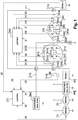
- la
figure 1 illustre un exemple de système électrique selon l'invention ; - la
figure 2 illustre une deuxième variante de réalisation du dispositif de transfert d'énergie selon l'invention ; - la
figure 3 illustre une troisième variante de réalisation du dispositif de transfert d'énergie selon l'invention ; - la
figure 4 illustre une quatrième variante de réalisation du dispositif de transfert d'énergie selon l'invention ; - la
figure 5 illustre une cinquième variante de réalisation du dispositif de transfert d'énergie selon l'invention ; - la
figure 6 illustre une sixième variante de réalisation du dispositif de transfert d'énergie selon l'invention ; - la
figure 7 illustre une septième variante de réalisation du dispositif de transfert d'énergie selon l'invention ; - la
figure 8 illustre une huitième variante de réalisation du dispositif de transfert d'énergie selon l'invention ; - la
figure 9 illustre schématiquement un diagramme d'évolution de la résistance d'un ensemble d'interrupteurs en fonction de sa commande de tension ; - la
figure 10 illustre un diagramme d'évolution temporelle d'une commande de fonctionnement d'un interrupteur élémentaire.
- the
figure 1 illustrates an example of an electrical system according to the invention; - the
figure 2 illustrates a second alternative embodiment of the energy transfer device according to the invention; - the
figure 3 illustrates a third alternative embodiment of the energy transfer device according to the invention; - the
figure 4 illustrates a fourth alternative embodiment of the energy transfer device according to the invention; - the
figure 5 illustrates a fifth alternative embodiment of the energy transfer device according to the invention; - the
figure 6 illustrates a sixth alternative embodiment of the energy transfer device according to the invention; - the
figure 7 illustrates a seventh alternative embodiment of the energy transfer device according to the invention; - the
figure 8 illustrates an eighth alternative embodiment of the energy transfer device according to the invention; - the
figure 9 schematically illustrates a diagram of the evolution of the resistance of a set of switches as a function of its voltage control; - the
figure 10 illustrates a diagram of the time evolution of an operating command of an elementary switch.
Les dessins annexés pourront non seulement servir à compléter l'invention, mais aussi contribuer à sa définition, le cas échéant.The accompanying drawings may not only serve to complete the invention, but also contribute to its definition, if necessary.
Dans ce qui suit, on considère à titre d'exemple non limitatif que le système électrique présenté est embarqué à bord d'un véhicule comportant un moteur thermique comportant un réseau de bord comprenant des consommateurs.In what follows, it is considered by way of nonlimiting example that the electrical system presented is on board a vehicle comprising a heat engine comprising an on-board network comprising consumers.
Mais l'invention n'est pas limitée à ce mode de réalisation. En effet, elle concerne tout système électrique et électronique comportant au moins deux stockeurs d'énergie et un consommateur.However, the invention is not limited to this embodiment. Indeed, it relates to any electrical and electronic system comprising at least two energy stores and a consumer.
En référence à la
Le dispositif de gestion de transfert d'énergie électrique 5 comporte quatre bornes : d'une part, une première borne M, qui est une borne négative connectée à une masse du véhicule, et d'autre part, une deuxième borne P1, une troisième borne P2 et une quatrième borne P3 qui sont des bornes positives.The electrical energy transfer management device 5 has four terminals: on the one hand, a first terminal M, which is a negative terminal connected to an earth of the vehicle, and on the other hand, a second terminal P1, a third terminal P2 and a fourth terminal P3 which are positive terminals.
Le producteur d'énergie électrique 1 est relié électriquement d'un côté à la deuxième borne P1 du dispositif 5, avec un faisceau électrique (résistif et inductif), et de l'autre côté à la masse. L'alternateur 2 est aussi relié électriquement d'un côté à la deuxième borne P1 du dispositif 5, avec un faisceau électrique (résistif et inductif), et de l'autre côté à la masse. Le réseau de bord secondaire 4b est aussi relié électriquement d'un côté à la deuxième borne P1 du dispositif 5, avec un faisceau électrique (résistif et inductif), et de l'autre côté à la masse. Le premier stockeur d'énergie électrique 3 est aussi relié électriquement d'un côté à la deuxième borne P1 du dispositif 5.1 et de l'autre côté à la masse.The producer of
Le réseau de bord principal 4a est relié électriquement d'un côté à la troisième borne P2 du dispositif 5.1 avec au moins un faisceau et de l'autre côté à la masse.The main on-
Le deuxième stockeur 6 est relié électriquement d'un côté à la quatrième borne P3 du dispositif 5.1 et de l'autre côté à la masse avec des faisceaux.The second store 6 is electrically connected on one side to the fourth terminal P3 of the device 5.1 and on the other side to ground with beams.
L'alternateur 1 (ou alterno-démarreur) est utilisé pour la fourniture de puissance électrique au réseau de bord 4a, 4b du véhicule, pour les redémarrages du moteur thermique et pour les phases dite de BOOST. Lors d'une phase de BOOST, l'alternateur est utilisé pour une fournir du couple au moteur thermique en phase de roulage. En phase de BOOST, l'alternateur devient donc consommateur de courant.The alternator 1 (or alternator-starter) is used for supplying electrical power to the on-
Le démarreur 2 est utilisé pour les premiers démarrages du véhicule et éventuellement, selon la configuration du véhicule, pour les redémarrages du véhicule.
Le premier stockeur d'énergie électrique 3, par exemple de type batterie plomb 12V, est utilisé notamment pour le démarrage et le redémarrage, pour l'alimentation des consommateurs du réseau de bord principal 4a et secondaire 4b pendant les phases de veille du véhicule.The first
Le véhicule comporte aussi un capteur 8 collectant des données relatives au premier stockeur 3 : le courant du premier stockeur 3, la tension du premier stockeur 3, la température du premier stockeur 3, une estimation de l'état de charge du premier stockeur 3. De façon alternative, si le premier stockeur 3 est instrumenté (mesure de courant et de tension), il est possible d'exploiter ces informations, sans avoir recourt au capteur 8.The vehicle also includes a
Le réseau de bord principal 4a inclut des éléments électriques du véhicule tels que des calculateurs et des équipements électriques, par exemple, des équipements de confort, les organes sécuritaires ainsi que les autres équipements électriques n'entrant pas dans les catégories précédemment citées.The main on-
De façon optionnelle, le véhicule comporte un réseau de bord secondaire 4b comportant uniquement des consommateurs (ou organes) qui ne sont pas perturbés pendant les phases de démarrage, de redémarrage et de BOOST.Optionally, the vehicle includes a secondary on-
Le deuxième stockeur 6 (ou stockeur secondaire), par exemple une batterie lithium-ion, est utilisé pour alimenter le réseau de bord principal 4a pendant l'usage du véhicule (hors veille).The second store 6 (or secondary store), for example a lithium-ion battery, is used to supply the main on-
Le véhicule comporte aussi un superviseur 7 apte à collecter et transmettre des données du véhicule.The vehicle also includes a
Le véhicule comporte aussi des éléments de distribution électrique 10, 11, 12. Ces éléments de distribution électrique 10, 11, 12 sont par exemple des faisceaux ayant des caractéristiques inductives et résistives. Les faisceaux contribuent au bon fonctionnement du système grâce à leur caractéristique résistive et inductive.The vehicle also includes
Comme expliqué précédemment, le dispositif 5.1 comporte quatre bornes :
- la première borne M, borne négative connectée à une masse du véhicule,
- la deuxième borne P1, borne positive connectée au
premier stockeur 3, au démarreur 2 et à l'alternateur 1 et au réseau de bordsecondaire 4b ; - la troisième borne P2, borne positive connectée au réseau de bord principal 4a ;
- la quatrième borne P3, borne positive connectée au deuxième stockeur 6.
- the first terminal M, negative terminal connected to an earth of the vehicle,
- the second terminal P1, positive terminal connected to the
first storage device 3, to thestarter 2 and to thealternator 1 and to the secondary on-board network 4b; - the third terminal P2, positive terminal connected to the main on-
board network 4a; - the fourth terminal P3, positive terminal connected to the second storage device 6.
Le dispositif 5.1 comporte deux ensembles d'interrupteurs 51,53, aussi appelé interrupteurs de puissance, (par exemple de type MOSFET, acronyme anglais de Metal Oxide Semiconductor Field Effect Transistor - qui se traduit par transistor à effet de champ à structure métal-oxyde-semiconducteur) :
Le premier ensemble d'interrupteurs 51 comporte un premier interrupteur élémentaire 51a, un deuxième interrupteur élémentaire 51b et une première diode 51c, une troisième diode 51e et un interrupteur élémentaire 51d, dit quatrième interrupteur élémentaire.Device 5.1 comprises two sets of
The first set of
Il peut y avoir plusieurs deuxièmes interrupteurs élémentaires 51b et diodes 51c montés en parallèles. Dans ce cas, les deuxièmes interrupteurs élémentaires 51b sont commandés simultanément.There may be several second
Il peut aussi y avoir plusieurs quatrièmes interrupteurs élémentaires 51d et troisième diodes 51e montés en parallèles. Dans ce cas, les quatrièmes interrupteurs élémentaires 51d sont commandés simultanément.There may also be several fourth
La première diode 51c est mise en place pour la sûreté de fonctionnement. La diode est en redondance des interrupteurs élémentaires en cas de défaillance en circuit ouvert.The
Le premier interrupteur élémentaire (par exemple un interrupteur de type électromécanique) 51a est normalement fermé. Il est utilisé pour alimenter le véhicule pendant une phase parking du véhicule (veille du véhicule).The first elementary switch (for example an electromechanical type switch) 51a is normally closed. It is used for power the vehicle during a vehicle parking phase (vehicle standby).
Le deuxième interrupteur élémentaire 51b fonctionne :
- en ON (fermeture): Dans ce mode de pilotage, il n'y a pas de limitation du courant quel que soit le sens du courant ;
- en OFF (ouverture): pas de passage de courant dans le
premier ensemble d'interrupteurs 51 dans le sens du deuxième stockeur 6 vers lepremier stockeur 3 lorsque le premier interrupteur élémentaire 51a ouvert. - en PWM (commande piloté / mode automatique) dans le sens deuxième stockeur 6 vers
premier stockeur 3 de façon à limiter la décharge du deuxième stockeur 6 vers lepremier stockeur 3. Cette limitation est obtenue à partir d'une consigne de courant et/ou de tension à respecter Dans le mode PWM, il n'y a pas de limitation de courant dans le sens stockeur 3 vers l'ensemble stockeur 6 et réseau de bord 4a, nous sommes dans un fonctionnement similaire au mode ON puisque le courant est inférieur à la consigne de courant, - Filtrage actif : Fonctionnement en PWM combiné à un mode linéaire (voir explication ci-après) en association avec le quatrième interrupteur élémentaire 51d lorsque le troisième interrupteur 53a est piloté en PWM avec un passage du courant dans le sens
premier stockeur 3 vers deuxième stockeur 6.
- in ON (closing): In this control mode, there is no current limitation whatever the direction of the current;
- in OFF (opening): no current flow through the first set of
switches 51 in the direction from the second storage unit 6 to thefirst storage unit 3 when the firstelementary switch 51a is open. - in PWM (piloted control / automatic mode) in the direction from second storage 6 to
first storage 3 so as to limit the discharge from the second storage 6 to thefirst storage 3. This limitation is obtained from a current setpoint and / or voltage to be respected In PWM mode, there is no current limitation in thestorage direction 3 towards the storage assembly 6 and on-board network 4a, we are in an operation similar to ON mode since the current is lower at the current setpoint, - Active filtering: Operation in PWM combined with a linear mode (see explanation below) in association with the fourth
elementary switch 51d when thethird switch 53a is controlled in PWM with a current flow in the direction from thefirst storage 3 to the second storage 6 .
Le deuxième interrupteur élémentaire 51b est pilotable en tension dans le transfert d'énergie électrique (à partir de consigne de tension et de courant pour la construction du signal PWM). Tant que le courant, la tension et la puissance sont dans un gabarit défini par des valeurs de limitation, il n'y a pas d'écrêtage en tension, de limitation du courant ou de limitation de la puissance et le deuxième interrupteur élémentaire 51b se comporte comme un interrupteur fermé. Si le courant, la tension ou la puissance est au-delà du gabarit défini, il y a un écrêtage en tension, ou une limitation en courant ou une limitation de la puissance et le deuxième interrupteur élémentaire 51b se comporte comme un hâcheur monodirectionnel. La stratégie de régulation que l'on met en place permet d'avoir une régulation en tension et en courant dans le transfert d'énergie électriqueThe second
Le pilotage de 51b permet une mise en place d'une limitation de courant dans le sens du deuxième stockeur 6 vers l'ensemble comprenant le premier stockeur 3 et l'alterno-démarreur 1 sous contrainte de tension du réseau de bord principal 4a (de façon à maintenir un tension minimale dans le réseau de bord principal 4a). Cette limitation de courant est utilisée pour contribuer à la fonction BOOST et fournir du courant à l'alterno-démarreur 1 qui contribue alors à fournir de couple au moteur thermique en phase de roulage véhicule.The control of 51b allows a current limitation to be set up in the direction of the second storage device 6 towards the assembly comprising the
Le pilotage de 51b ne permet pas de limitation du courant dans le sens du premier stockeur 3 vers le deuxième stockeur 6 notamment à cause de la première diode.The control of 51b does not allow limitation of the current in the direction of the
Le deuxième interrupteur 51b peut être piloté :
- de façon manuelle, à partir d'une consigne de courant de décharge (de 0 à Imax);
- de façon automatique, sous autorisation : dès que la tension du
premier stockeur 3 passe sous un seuil de tension prédéterminé, le superviseur autorise de la décharge du deuxième stockeur 6 vers l'ensemble comprenant lepremier stockeur 3 et l'alterno-démarreur 1 sous la contrainte d'une consigne de courant maximal Imax de décharge et avec le respect d'une tension minimale du réseau de bord principal 4a.
- manually, from a discharge current setpoint (from 0 to Imax);
- automatically, under authorization: as soon as the voltage of the
first storage device 3 falls below a predetermined voltage threshold, the supervisor authorizes the discharge of the second storage device 6 to the assembly comprising thefirst storage device 3 and the alternator-starter 1 under the constraint of a maximum current setpoint Imax of discharge and with compliance with a minimum voltage of the main on-board network 4a.
Le quatrième interrupteur élémentaire 51d fonctionne :
- en ON (fermeture manuelle), lorsque le deuxième interrupteur 51b est piloté pour transférer de l'énergie depuis la quatrième borne P3 vers la troisième borne P2.
- en PWM en mode linéaire pour réaliser un filtre actif lorsque le troisième interrupteur 53a est en mode PWM avec un passage du courant dans le sens
premier stockeur 3 vers deuxième stockeur 6.
- in ON (manual closing), when the
second switch 51b is controlled to transfer energy from the fourth terminal P3 to the third terminal P2. - in PWM in linear mode to produce an active filter when the
third switch 53a is in PWM mode with a current flow in the direction from thefirst storage device 3 to the second storage device 6.
Par exemple, le quatrième interrupteur élémentaire 51d peut être un composant électronique de puissance de type MOSFET, et dont l'état (ouvert ou partiellement ouvert ou fermé) dépend d'une commande de tension CIP, par exemple égale à 0,5 V. On a schématiquement illustré sur la
Pour résumé, lorsque la limitation en courant pour la recharge du deuxième stockeur 6 est active (autrement dit, le troisième interrupteur 53a est piloté en PWM), les deuxième 51b et quatrièmes 51d interrupteurs sont également pilotés en PWM combiné avec un pilotage en mode linéaire. Ils peuvent être pilotés de manières synchrones ou asynchronesTo summarize, when the current limitation for recharging the second storage device 6 is active (in other words, the
Le deuxième ensemble d'interrupteurs 53 comporte un troisième interrupteur 53a, une deuxième diode 53b, une quatrième diode 53d et un cinquième interrupteur élémentaire 53c.The second set of
Il peut y en avoir plusieurs interrupteurs principaux 53 en parallèle. Les troisièmes interrupteurs élémentaires 53a sont alors commandés simultanément.There may be several
Il peut aussi y avoir plusieurs cinquièmes interrupteurs élémentaires 53c et quatrièmes diodes 53d montés en parallèles. Dans ce cas, les cinquièmes interrupteurs élémentaires 53c sont commandés simultanément.There may also be several fifth
Le troisième interrupteur 53a fonctionne :
- en ON (fermeture) : Dans ce sens, il n'y a pas de limitation du courant quel que soit le sens du courant ;
- en PWM (commande piloté / mode automatique) dans le sens de l'ensemble comprenant le
premier stockeur 3 et le générateur 1 vers le deuxième stockeur 6, de façon à limiter la recharge du premier stockeur 6. Cette limitation est obtenue à partir d'une consigne de courant et/ou de tension à respecter. Dans le mode PWM, il n'y a pas de limitation de courant dans le sens stockeur 6 vers l'ensemble stockeur 3/réseau de bordsecondaire 4b et réseau de bord principal 4a, nous sommes dans un fonctionnement similaire au mode ON puisque le courant est inférieur à la consigne de courant - Filtrage actif : Fonctionnement en PWM combiné à un mode linéaire (voir explication ci-après) en association avec le cinquième interrupteur élémentaire 53c lorsque le deuxième interrupteur 51b est piloté en PWM avec un passage du courant dans le sens deuxième stockeur 6 vers le
premier stockeur 3.
- in ON (closing): In this sense, there is no current limitation whatever the direction of the current;
- in PWM (piloted control / automatic mode) in the direction of the assembly comprising the
first storage device 3 and thegenerator 1 towards the second storage device 6, so as to limit the recharging of the first storage device 6. This limitation is obtained from a current and / or voltage set point to be observed. In PWM mode, there is no current limitation in the storage direction 6 towards thestorage assembly 3 / secondary on-board network 4b and main on-board network 4a, we are in an operation similar to ON mode since the current is less than the current setpoint - Active filtering: Operation in PWM combined with a linear mode (see explanation below) in association with the fifth
elementary switch 53c when thesecond switch 51b is controlled in PWM with a current flow in the direction of the second storage device 6 towards thefirst storage device 3.
Le troisième interrupteur 53a est pilotable en tension dans le transfert d'énergie électrique (à partir de consigne en tension et en courant pour la construction du PWM). Tant que le courant, la tension et la puissance sont dans un gabarit défini par des valeurs de limitation, il n'y a pas d'écrêtage en tension, de limitation du courant ou de limitation de la puissance et le troisième interrupteur 53a se comporte comme un interrupteur fermé. Si le courant, la tension ou la puissance est au-delà du gabarit défini, il y a un écrêtage en tension, ou une limitation en courant ou une limitation de la puissance et le troisième interrupteur 53a se comporte comme un hâcheur monodirectionnel. La stratégie de régulation que l'on met en place permet d'avoir une régulation en tension et en courant.The
Le pilotage du troisième interrupteur 53a permet la mise en place d'une limitation de courant dans le sens de l'ensemble comprenant le premier stockeur 3 le démarreur 1 et l'alternateur 2 vers le deuxième stockeur 6 sous contraintes :
- D'une consigne en courant de recharge maximal du deuxième stockeur 6 ;
- D'une tension réseau de bord principal 4a minimale à garantir ;
- D'une tension maximale admissible du deuxième stockeur 6 ;
- D'une consigne de prélèvement maximal de courant sur l'alternateur.
- A setpoint for the maximum recharging current of the second storage device 6;
- A minimum main on-
board network voltage 4a to be guaranteed; - Of a maximum admissible voltage of the second storage device 6;
- A maximum current drawdown instruction on the alternator.
Le pilotage du troisième interrupteur 53a ne permet pas de limitation du courant dans le sens du deuxième stockeur 6 vers l'ensemble comprenant le premier stockeur 3 le démarreur 1 et l'alternateur 2.Piloting the
Le cinquième interrupteur élémentaire 53c fonctionne :
- en ON (fermeture manuelle), lorsque le dispositif 5.1 est piloté pour transférer de l'énergie depuis la quatrième borne P3 vers la troisième borne P2 (dans le sens deuxième stockeur 6 vers réseau de bord 4a) ou pour transférer de l'énergie depuis la deuxième borne P1 vers la quatrième borne P3 (dans le sens
premier stockeur 3 vers deuxième stockeur 6). - en PWM combiné à un mode linéaire pour réaliser un filtre actif lorsque le deuxième interrupteur 51b est en mode PWM avec un passage du courant dans le sens deuxième stockeur 6 vers le
premier stockeur 3.
- in ON (manual closing), when the device 5.1 is controlled to transfer energy from the fourth terminal P3 to the third terminal P2 (in the direction of second storage device 6 to on-
board network 4a) or to transfer energy from the second terminal P1 towards the fourth terminal P3 (in the direction of thefirst storage device 3 towards the second storage device 6). - in PWM combined with a linear mode to produce an active filter when the
second switch 51b is in PWM mode with a current flow in the direction of the second storage device 6 towards thefirst storage device 3.
En résumé, le deuxième interrupteur élémentaire 51b et le troisième interrupteur élémentaire 53a se comporte chacun comme un hacheur monodirectionnel. En revanche, le dispositif 5, au global, se comporte comme un abaisseur bidirectionnel.In summary, the second
Le dispositif selon l'invention 5.1 comporte aussi un interrupteur électromécanique 54 normalement ouvert permettant une isolation du deuxième stockeur 6 par exemple en cas d'atteinte des conditions aux limites du deuxième stockeur 6 (durabilité du stockeur) Il est également ouvert lorsque le véhicule est en veille : la batterie lithium n'est pas utilisée pendant la veille du véhicule ou d'une défaillance de l'ensemble d'interrupteurs 53 à l'état fermé (toujours passant).The device according to the invention 5.1 also includes an
Le dispositif 5.1 permet, en pilotant les interrupteurs principaux 51, 53, d'alimenter les consommateurs du réseau de bord 4a et 4b avec différentes sources d'énergie :
- Soit à partir de l'alternateur 1 avec une consigne de tension pouvant varier de 13 à 16V ;
- Soit à partir de l'ensemble
premier stockeur 3, alternateur 1 par une gestion des interrupteurs principaux 51, 53. - Soit à partir du deuxième stockeur 6 par une gestion des interrupteurs principaux 51, 53.
- Either from
alternator 1 with a voltage setpoint that can vary from 13 to 16V; - Or from the
first storage unit 3,alternator 1 by managing themain switches - Or from the second store 6 by managing the
main switches
Le dispositif selon l'invention comporte aussi deux mesures de courant 50a, 50b :
- Une première mesure de
courant 50a mesurant le courant passant par le deuxième interrupteur élémentaire 51b,la première diode 51c, le quatrième interrupteur élémentaire 51d et la troisièmediode 51e (le courant passant par le premier interrupteur élémentaire 51a n'est pas mesuré par la première decourant 50a) et qui est utilisée notamment pour la mesure de courant de recharge du premier stockeur 3 par le deuxième stockeur 6 ou pour l'aide au démarrage/ redémarrage par une fourniture de courant limité du deuxième stockeur 6 pour l'alternateur 1ou le démarreur 2. - Une deuxième mesure de
courant 50b mesurant la recharge du deuxième stockeur 6.
- A first
current measurement 50a measuring the current passing through the secondelementary switch 51b, thefirst diode 51c, the fourthelementary switch 51d and thethird diode 51e (the current passing through the firstelementary switch 51a is not measured by the first current 50a) and which is used in particular for measuring the charging current of thefirst storage device 3 by the second storage device 6 or for starting / restarting assistance by supplying limited current from the second storage device 6 for thealternator 1 orstarter 2. - A second
current measurement 50b measuring the recharge of the second storage device 6.
L'invention comporte aussi trois mesures de tensions 55a, 55b, 55c.The invention also includes three
La première mesure de tension 55a mesure la tension du premier stockeur 3 entre la deuxième borne P1 et la première borne M.The
La deuxième mesure de tension 55b mesure la tension du réseau de bord principal 4a entre la troisième borne P2 et la deuxième borne M.The
La troisième mesure de tension 55c mesure la différence de potentiel entre, d'une part, le premier ensemble d'interrupteurs 53 et l'interrupteur électromécanique 54 (potentiel positif) et, d'autre part, la borne M (potentiel négatif).The
Le dispositif selon l'invention 5.1 comporte aussi deux diodes de roue libre 56, 57.The device according to the invention 5.1 also includes two
La première diode de roue libre 56 est indispensable lors du fonctionnement en PWM du troisième interrupteur 53a, sinon la tension devient trop élevée, en raison des effets inductifs.The first
La deuxième diode de roue libre 57 est indispensable lors du fonctionnement en PWM du deuxième interrupteur 51b, sinon la tension devient trop élevée. Sans diode, les surtensions peuvent détruire les interrupteursThe second
Le dispositif selon l'invention 5.1 comporte aussi un superviseur 58. Le superviseur 58 est configuré pour générer un signal de pilotage C1, C2, correspondant au mode de fonctionnement déterminé, pour le deuxième interrupteur élémentaire 51b et le troisième interrupteur élémentaire 53a. Ces signaux de pilotage permettent d'ouvrir et de fermer les interrupteurs 51b, 53a afin de réguler les valeurs de la tension et du courant associées au transfert d'énergie lorsqu'une limitation du courant et/ou de la tension est nécessaire.The device according to the invention 5.1 also includes a
Les différents éléments de l'architecture de la
L'alternateur 1 communique [a] avec le superviseur véhicule 7. L'alternateur 1 envoie au superviseur véhicule 7 des données alternateur avec par exemple la charge de l'alternateur. Le superviseur véhicule 7 envoie vers l'alternateur 1 des consignes de pilotage de l'alternateur.The
Le réseau de bord principal 4a envoie [b] au superviseur véhicule 7 des informations concernant l'état des consommateurs électriques présents sur le réseau de bord principal 4a. Plus précisément, ce sont certains constituants (des consommateurs) du réseau de bord principal 4a qui envoient des informations au superviseur 7. Cette information permet au superviseur véhicule 7 de déterminer une plage de fonctionnement nominale en tension du réseau de bord principal 4a en définissant une tension minimale (Umin) et une tension maximale (Umax) à garantir.The main on-
Le réseau de bord secondaire 4b envoie [c] au superviseur véhicule 7 des informations concernant l'état des consommateurs électriques présents sur le réseau de bord secondaire 4b. Plus précisément, ce sont certains constituants (des consommateurs) du réseau de bord secondaire 4b qui envoient des informations au superviseur 7. Cette information permet au superviseur véhicule 7 de déterminer une plage de fonctionnement nominale en tension du réseau de bord secondaire 4b en définissant une tension minimale (Umin) et une tension maximale (Umax) à garantir.The secondary on-
Le premier stockeur communique [d] au superviseur véhicule 7 des informations concernant le premier stockeur 3, a minima : la température du premier stockeur, le courant du premier stockeur, la tension du premier stockeur, estimation de l'état de charge du premier stockeur.The first storage device communicates [d] to the
Le superviseur du dispositif 5.1 reçoit [e] la première mesure de tension 55a entre P1 et M. Cette mesure représente la tension du premier stockeur 3 (c'est une image à la chute de tension prêt).The supervisor of the device 5.1 receives [e] the
Le superviseur 58 du dispositif 5.1 reçoit [f] la première mesure de courant 50a dans le sens réseau de bord principale 4a vers premier stockeur 3 sur la deuxième borne P1 du dispositif 5.The
Le superviseur 58 du dispositif 5.1 pilote [g] le quatrième interrupteur élémentaire 51d, comme expliqué précédemment soit en pilotage de type ON, OFF, soit en pilotage en commutation (PWM) combiné à un mode linéaire pour réaliser un filtre actif.The
Le superviseur 58 du dispositif 5.1 pilote [h] le premier interrupteur élémentaire 51a.The
Le superviseur 58 du dispositif 5.1 pilote aussi [i] le deuxième interrupteur élémentaire 51b. Il s'agit d'un pilotage de type ON (autrement dit, en mode passant bidirectionnel), OFF (autrement dit, bloqué dans le sens réseau de bord secondaire 4b vers réseau de bord principal 4a, ou en commutation (PWM) en mode limitation de courant dans le sens du deuxième stockeur 6 vers le premier stockeur 3 et passant dans le sens stockeur 3 vers réseau de bord 4a, ou en commutation (PWM) combiné à un mode linéaire, conjointement avec le quatrième interrupteur élémentaire 51d, pour réaliser un filtre actif.The
Le superviseur 58 du dispositif 5.1 reçoit [j] la deuxième mesure de tension entre P2 et M. Cette mesure représente la tension du réseau de bord principal 4a.The
Le superviseur 58 du dispositif 5.1 pilote [k] le troisième interrupteur élémentaire 53a. Il s'agit d'un pilotage de type ON (autrement dit, passant quel que soit le sens du courant et la valeur du courant), OFF ou en commutation (PWM) en mode limitation de courant de recharge du deuxième stockeur 6 dans le sens alternateur 1 vers deuxième stockeur 6, ou en commutation (PWM) combiné à un mode linéaire, conjointement avec le cinquième interrupteur élémentaire 53c, pour réaliser un filtre actif.The
Le superviseur 58 du dispositif 5.1 pilote aussi [l] le cinquième interrupteur élémentaire 53c, comme expliqué précédemment soit en pilotage de type ON, OFF, soit en pilotage en commutation (PWM) combiné à un mode linéaire pour réaliser un filtre actif.The
Le superviseur 58 du dispositif 5.1 pilote aussi [n] l'interrupteur électromécanique 54.The
Le superviseur 58 du dispositif 5.1 reçoit [o] la deuxième mesure de courant 50b du deuxième stockeur 6.The
Le superviseur 58 du dispositif 5.1 reçoit [m] la troisième mesure de tension 55c Cette mesure représente la tension entre le cinquième interrupteur 53c et l'interrupteur électromécanique 54, d'une part, et le point de masse M, d'autre part.The
Le superviseur véhicule 7 et le superviseur 58 du dispositif 5.1 échangent [p] des informations
Le superviseur véhicule 7 [q] reçoit des données du deuxième stockeur 6 (par exemple, température, courant, tension, état de charge, ...).The
The vehicle supervisor 7 [q] receives data from the second storage device 6 (for example, temperature, current, voltage, state of charge, etc.).
On a schématiquement illustré sur la
Lorsque le découpage (ou la commutation) est de type dit « à modulation de largeur d'impulsion » (ou PWM (pour « Puise Width Modulation »)), la commande de fonctionnement à 0 est notée « PWM=0 » et la commande de fonctionnement à 1 est notée « PWM=1 ». On notera que lorsque la commande de fonctionnement est à 1 (PWM=1), le dispositif 5.1 de gestion de transfert d'énergie prélève de la puissance depuis la deuxième borne (P1), et donc il y a du courant qui passe dans le deuxième interrupteur élémentaire 51b et dans le quatrième interrupteur élémentaire 51d en vue d'alimenter la troisième borne P2 (reliée au réseau de bord) et la quatrième borne P3 (reliée au deuxième stockeur).When the cutting (or switching) is of the so-called “pulse width modulation” (or PWM (for “Puise Width Modulation”)) type, the operating command at 0 is denoted “PWM = 0” and the command operating at 1 is noted "PWM = 1". Note that when the operating command is at 1 (PWM = 1), the energy transfer management device 5.1 takes power from the second terminal (P1), and therefore there is current flowing in the second
La consigne URA1 lim de limitation de tension aux bornes du premier réseau de consommation RA1 est une information qui peut être fournie par le superviseur 58.The setpoint U RA1 lim for limiting the voltage across the terminals of the first consumption network RA1 is information which can be supplied by the
On notera également que lorsque le deuxième interrupteur élémentaire 51b et/ou dans le quatrième interrupteur élémentaire 51d a plusieurs états intermédiaires (comme c'est le cas de ceux de type MOSFET (voir
Par exemple, cette loi prédéfinie peut être non linéaire. Mais dans une variante de réalisation cette loi prédéfinie pourrait être linéaire.For example, this predefined law can be non-linear. But in a variant embodiment, this predefined law could be linear.
Pendant le contrôle selon la loi prédéfinie (par exemple non linéaire), la commande de fonctionnement CIP de chacun des deuxième 51b et quatrième 51d interrupteurs élémentaires varie entre CIP 1 et CIP 2, de façon à induire une chute de la tension V2 à la troisième borne P2 sous ou au niveau de la consigne URA1 lim de limitation de tension.During the control according to the predefined law (for example non-linear), the operating command C IP of each of the second 51b and fourth 51d elementary switches varies between C IP 1 and C IP 2 , so as to induce a drop in the voltage V2 at the third terminal P2 under or at the level of the U RA1 lim voltage limit setpoint.
On notera que le superviseur 58 peut être agencé pour contrôler les placements des deuxième 51b et quatrième 51d interrupteurs élémentaires de façon sensiblement synchronisée ou bien de façon désynchronisée.It will be noted that the
On peut noter que le superviseur est aussi apte à piloter le deuxième ensemble d'interrupteur 53 comme filtre actif lorsque l'interrupteur 51 est piloté pour limiter la tension.It can be noted that the supervisor is also able to control the second set of
On notera également que le superviseur 58 peut être agencé pour débuter le contrôle selon la loi prédéfinie avec un premier décalage temporel prédéfini ε1 après la réception d'une première mesure de tension V2 à la troisième borne P2 supérieure à la consigne URA1 lim de limitation de tension à la troisième borne P2. Cette option est destinée à retarder de ε1 le démarrage du contrôle selon la loi prédéfinie, afin d'éviter des perturbations. Physiquement cette valeur mesurée V2 sera différente de 0, car elle est liée à la chaîne d'acquisition et de traitement. Dans ce cas, le démarrage du contrôle selon la loi prédéfinie commence au plus tard à l'instant t = α.T + ε1. Le premier décalage temporel prédéfini ε1 n'intervient qu'au démarrage du contrôle.It will also be noted that the
Par exemple, ε1 peut être choisie égale à zéro (0) par défaut.For example, ε1 can be chosen equal to zero (0) by default.
On notera également que le superviseur 58 peut être agencé pour arrêter le contrôle selon la loi prédéfinie avec un second décalage temporel ε2 fonction de la mesure de tension V2 à la troisième borne P2. Ce second décalage temporel ε2 est un retard temporel qui est la conséquence d'une demande de maintien de l'usage en mode linéaire des deux moyens d'interruption. Cette option est destinée à retarder de ε2 l'arrêt du contrôle selon la loi prédéfinie, afin d'atténuer l'effet inductif de l'architecture électrique et du générateur de courant par une réduction des pics de surtension et donc une réduction des perturbations électromagnétiques.It will also be noted that the
La
- le premier interrupteur élémentaire 51a,
- le premier ensemble d'interrupteur 51 comprenant, le deuxième interrupteur 51b, le quatrième interrupteur élémentaire 51d,
la première diode 51c et la troisièmediode 51e, - le deuxième ensemble d'interrupteur 53 comprenant le troisième interrupteur élémentaire 53a, la deuxième
diode 53b, la première diode de rouelibre 56, l'interrupteur électromécanique 54.
- the first
elementary switch 51a, - the
first switch assembly 51 comprising, thesecond switch 51b, the fourthelementary switch 51d, thefirst diode 51c and thethird diode 51e, - the
second switch assembly 53 comprising the thirdelementary switch 53a, thesecond diode 53b, the firstfreewheeling diode 56, - the
electromechanical switch 54.
Dans ce mode de réalisation, le troisième interrupteur 53a peut être piloté en PWM (commande piloté / mode automatique) dans le sens de l'ensemble comprenant le premier stockeur 3 et le générateur 1 vers le deuxième stockeur 6, de façon à limiter la recharge du premier stockeur 6. Le deuxième 51b et le quatrième 51d interrupteur peuvent être pilotés en PWM combiné à un mode linéaire lorsque, le troisième interrupteur 53a est piloté en PWM avec un passage du courant dans le sens premier stockeur 3 et le générateur 1 vers le deuxième stockeur 6, de façon à obtenir un filtrage actif.In this embodiment, the
La
- une première inductance L1, reliée à la deuxième borne P1 et au premier interrupteur élémentaire 51a,
- une deuxième inductance L2, reliée à la quatrième borne P3 et à l'interrupteur électromécanique 54,
- une deuxième diode de roue
libre 57 dont l'anode est reliée à la première borne (M) et la cathode est reliée à l'anode de la première diode (51c).
- a first inductor L1, connected to the second terminal P1 and to the first
elementary switch 51a, - a second inductor L2, connected to the fourth terminal P3 and to the
electromechanical switch 54, - a second
freewheeling diode 57 whose anode is connected to the first terminal (M) and the cathode is connected to the anode of the first diode (51c).
Dans ce mode de réalisation, le deuxième 51b interrupteur élémentaire peut en outre être piloté en PWM (commande piloté / mode automatique) dans le sens deuxième stockeur 6 vers premier stockeur 3 de façon à limiter la décharge du deuxième stockeur 6 vers le premier stockeur 3. La deuxième diode de roue libre 57 est nécessaire pour ce pilotage en PWM. Par contre les inductances L1, L2 ne sont pas indispensables.In this embodiment, the second
La
La
Dans ce mode de réalisation, le cinquième interrupteur élémentaire 53c peut être piloté en PWM combiné à un mode linéaire pour réaliser un filtre actif lorsque le deuxième interrupteur 51b est en mode PWM avec un passage du courant dans le sens deuxième stockeur 6 vers le premier stockeur 3.In this embodiment, the fifth
La
La
La
Claims (8)
- An energy transfer control device (5.1-5.8) comprising a first terminal (M) intended to be connected to an electrical ground, second terminal (P1) intended to be connected to a first store (3) and to a producer of energy (1), a third terminal (P2) intended to be connected to at least one electrical consumer, and a fourth terminal (P3) intended to be connected to a second store (6) of electrical energy, said device (5.1-5.8) further including a first set of switches (51) coupled on the one hand to the second terminal (P1) and on the other hand to the third terminal (P2), a second set of switches (53) coupled on the one hand to the fourth terminal (P3) and on the other hand to the third terminal (P2), the first set of switches (51) comprising a first diode (51c), the cathode of which is connected to the third terminal (P2) and a second basic switch (51b) mounted in parallel with the first diode (51c), the second set of switches (53) comprising a second diode (53b), the cathode of which is connected to the third terminal (P2), characterized in that the first set of switches (51) further comprises:- a first freewheeling diode (56), the anode of which is connected to the first terminal (M) and the cathode of which is coupled to the anode of the second diode (53b),- a third diode (51e), the anode of which is connected to the anode of the first diode (51c), and- a basic switch (51d), designated as fourth basic switch, mounted in parallel with the third diode (51e),and in that, said third basic switch (53a) being adapted to be driven by a pulse width modulation signal, said second basic switch (51b) and fourth basic switch (51d) being with at least three states, including at least one partially on intermediate state, an open state and a closed state, and being adapted to be driven by a pulse width modulation signal, it further comprises a supervisor (58) able to deliver:- a modulated signal at the third basic switch (53a) so as to limit the current passing through said third basic switch (53a), and- a modulated signal at the second basic switch (51b) and at the fourth basic switch (51d) so as to control the placement of said basic switches (51b, 51d) in an intermediate state so as to limit variations of voltages, at the level of the third terminal (P2), when the third basic switch (53a) is driven by a modulated signal.
- The energy transfer control device (5.1-5.8) according to Claim 1, characterized in that, during a transfer of energy from the second terminal (P1) to the fourth terminal (P3), the modulated signal controls the second basic switch (51b) and the fourth basic switch (51d) so that:- the second basic switch (51b) and the fourth basic switch (51d) are in the intermediate state, if the voltage at the level of the third terminal (P2) is greater than a predetermined threshold when the third basic switch (53a) is in an open state during the driving by the modulated signal, the second basic switch (51b) and the fourth basic switch (51d) being in the closed state if the voltage at the level of the third terminal (P2) is less than the predetermined threshold and- the second basic switch (51b) and the fourth basic switch (51d) are in a closed state when the third basic switch (53a) is in a closed state.
- The energy transfer control device (5.2-5.8) according to one of Claims 1 to 2, characterized in that it further comprises a second freewheeling diode (57), the anode of which is connected to the first terminal (M) and the cathode is connected to the anode of the first diode (51c) or to the cathode of the third diode (51e), the supervisor (58) being, furthermore, able to be deliver a modulated signal at the second basic switch (51b) so as to limit the current passing through said second basic switch (51b), during a transfer of energy from the fourth terminal (P3) to the third terminal (P2).
- The energy transfer control device (5.4-5.8) according to the preceding claim, characterized in that the second set of switches (53) further comprises:- a fourth diode (53d), the anode of which is connected to the anode of the second diode (53b),- a fifth basic switch (53c), mounted in parallel with the fourth diode (53d).
- The energy transfer control device (5.4-5.8) according to the preceding claim, characterized in that, the third basic switch (53a) and fifth basic switch (53c) being with at least three states, including at least one partially on intermediate state, an on state and a non-on state, the supervisor (58) being, furthermore, able to delivery a modulated signal so that:- the current passing through said second basic switch (51b) is limited,- the third basic switch (53a) and the fifth basic switch (53c) are in the intermediate state if the voltage at the level of the third terminal (P2) is greater than a predetermined threshold when the first basic switch (51b) is in an open state during the driving by the modulated signal, the third basic switch (53a) and the fifth basic switch (53c) being in the closed state if the voltage at the level of the third terminal (P2) is less than the predetermined threshold and- the third basic switch (53a) and the fifth basic switch (53c) are in a closed state when the first basic switch (51b) is in a closed state.
- The energy transfer control device (5.4-5.8) according to the preceding claim, characterized in that the cathode of the first freewheeling diode (56) is connected to the anode of the second diode (53b) or to the cathode of the fourth diode (53d).
- An electrical system of a vehicle comprising a producer of energy (1), a first store of energy (3), a second store of energy (6) and a main on-board network (4a) comprising at least one electrical consumer, characterized in that it further comprises an energy transfer control device (5.1-5.8) according to one of the preceding claims, the second terminal (P1) being connected to the first store (3) and to the producer of energy (1), the third terminal (P2) being connected to the on-board network (4a), the fourth terminal (P3) being connected to the second store (6), the first terminal (M) being connected to an electrical ground of the vehicle.
- A vehicle comprising an energy transfer control device (5.1-5.8) according to one of Claims 1 to 6 or an electrical system according to Claim 7.
Applications Claiming Priority (2)
| Application Number | Priority Date | Filing Date | Title |
|---|---|---|---|
| FR1650715A FR3047367B1 (en) | 2016-01-29 | 2016-01-29 | ENERGY TRANSFER MANAGEMENT DEVICE WITH ACTIVE CONTROL OF ELECTROMAGNETIC DISTURBANCES |
| PCT/FR2017/050053 WO2017129877A1 (en) | 2016-01-29 | 2017-01-10 | Energy transfer control device with active control of electromagnetic interference |
Publications (2)
| Publication Number | Publication Date |
|---|---|
| EP3408920A1 EP3408920A1 (en) | 2018-12-05 |
| EP3408920B1 true EP3408920B1 (en) | 2020-04-22 |
Family
ID=56008684
Family Applications (1)
| Application Number | Title | Priority Date | Filing Date |
|---|---|---|---|
| EP17702908.9A Active EP3408920B1 (en) | 2016-01-29 | 2017-01-10 | Energy transfer control device with active control of electromagnetic interference |
Country Status (4)
| Country | Link |
|---|---|
| EP (1) | EP3408920B1 (en) |
| CN (1) | CN108604819B (en) |
| FR (1) | FR3047367B1 (en) |
| WO (1) | WO2017129877A1 (en) |
Families Citing this family (1)
| Publication number | Priority date | Publication date | Assignee | Title |
|---|---|---|---|---|
| FR3092210A1 (en) * | 2019-01-29 | 2020-07-31 | Psa Automobiles Sa | PROCESS FOR MANAGING THE POWER SUPPLY OF TWO ELECTRICAL NETWORKS OF A MOTOR VEHICLE CONNECTED TO EACH OTHER |
Family Cites Families (7)
| Publication number | Priority date | Publication date | Assignee | Title |
|---|---|---|---|---|
| US7880331B2 (en) * | 2006-12-29 | 2011-02-01 | Cummins Power Generation Ip, Inc. | Management of an electric power generation and storage system |
| DE102007062955B4 (en) * | 2007-12-21 | 2011-06-01 | Catem Develec Gmbh & Co. Kg | Circuit for voltage stabilization of a vehicle electrical system |
| CN102386637B (en) * | 2010-09-03 | 2013-11-13 | 凹凸电子(武汉)有限公司 | Battery management system and method for controlling vehicle |
| DE102008054706A1 (en) * | 2008-12-16 | 2010-06-17 | Robert Bosch Gmbh | Power supply network for a vehicle |
| JP5578014B2 (en) * | 2010-10-19 | 2014-08-27 | 株式会社デンソー | Battery system control device |
| GB2488968A (en) * | 2011-02-01 | 2012-09-19 | Land Rover Uk Ltd | Vehicle power management using diodes |
| FR3026903B1 (en) * | 2014-10-03 | 2018-03-23 | Psa Automobiles Sa. | IMPROVED ENERGY TRANSFER MANAGEMENT DEVICE |
-
2016
- 2016-01-29 FR FR1650715A patent/FR3047367B1/en active Active
-
2017
- 2017-01-10 WO PCT/FR2017/050053 patent/WO2017129877A1/en active Application Filing
- 2017-01-10 CN CN201780008642.8A patent/CN108604819B/en active Active
- 2017-01-10 EP EP17702908.9A patent/EP3408920B1/en active Active
Non-Patent Citations (1)
| Title |
|---|
| None * |
Also Published As
| Publication number | Publication date |
|---|---|
| FR3047367B1 (en) | 2018-02-16 |
| CN108604819B (en) | 2022-03-04 |
| FR3047367A1 (en) | 2017-08-04 |
| EP3408920A1 (en) | 2018-12-05 |
| WO2017129877A1 (en) | 2017-08-03 |
| CN108604819A (en) | 2018-09-28 |
Similar Documents
| Publication | Publication Date | Title |
|---|---|---|
| EP2718977B1 (en) | Device for generating photovoltaic energy with blocks of cells | |
| WO2010010271A2 (en) | Method and device for monitoring the start time of a heat engine of a vehicle | |
| FR2965124A1 (en) | ROTARY ELECTRIC MACHINE FOR VEHICLE | |
| WO2016097551A1 (en) | Method and device for diagnosing an electric-energy management device | |
| EP3408920B1 (en) | Energy transfer control device with active control of electromagnetic interference | |
| EP3202015B1 (en) | Improved power transfer management device | |
| EP2788228B1 (en) | Method of managing the electrical energy of a motor vehicle and motor vehicle implementing such a method | |
| WO2009000989A2 (en) | Method for controlling a rotary electric machine in case of load shedding and corresponding power control module | |
| EP3369151B1 (en) | Device for active control depending on a law, for an electric circuit with a dc/dc converter and electrical energy storage system mounted in series | |
| EP2561595B1 (en) | Method of controlling the regulation of a motor vehicle alternator, and corresponding devices | |
| EP2053720A1 (en) | Voltage-compensation interface device with low storage of energy in capacitive form and electrical network comprising this device | |
| EP2158672B1 (en) | Rotary electric machine and method for controlling same | |
| FR2996692A1 (en) | METHOD FOR MANAGING A SYSTEM FOR POWERING A DRIVING NETWORK OF A VEHICLE IN ELECTRICAL ENERGY | |
| EP3028356A1 (en) | System for managing a supply voltage of an onboard electrical network of a motor vehicle | |
| FR3039934A1 (en) | METHOD FOR MANAGING THE POWER SUPPLY OF A MOTOR VEHICLE | |
| EP1946972A1 (en) | Device for temporarily increasing the voltage for an automobile element | |
| EP2179502B1 (en) | Power supply unit for a home automation actuator and method of operation of said unit | |
| EP2817865B1 (en) | Method for managing the electrical energy of an electrical architecture of a motor vehicle, and motor vehicle implementing such a method | |
| EP2602910B1 (en) | Interface device between an electricity grid and consumer systems | |
| WO2007080349A1 (en) | Device for supplying the inductor of a rotating electrical machine | |
| FR3019396A1 (en) | VOLTAGE STABILIZATION SYSTEM | |
| FR2895953A1 (en) | Electrical network e.g. dual voltage network, protection device for motor vehicle, has control unit limiting parameters to reduce peak of current required by storage element, and regulator varying values of parameters based on network state | |
| FR2888058A1 (en) | On-board electrical installation for motor vehicle, has supervisor for regulating output power of reversible voltage converter to reduced power value and nominal power value based on speed of rotation of alternator | |
| FR3069396A1 (en) | VOLTAGE REGULATOR FOR A MOTOR VEHICLE ALTERNATOR OF AT LEAST ONE INDEPENDENT CIRCUIT FOR PROTECTION AGAINST OVERVOLTAGES | |
| FR2955433A1 (en) | Control device for adjusted power supply device of on-board network of e.g. car, has conversion unit assembled in parallel to switching unit to convert current into chosen voltage, where device determines controls according to state of load |
Legal Events
| Date | Code | Title | Description |
|---|---|---|---|
| STAA | Information on the status of an ep patent application or granted ep patent |
Free format text: STATUS: UNKNOWN |
|
| STAA | Information on the status of an ep patent application or granted ep patent |
Free format text: STATUS: THE INTERNATIONAL PUBLICATION HAS BEEN MADE |
|
| PUAI | Public reference made under article 153(3) epc to a published international application that has entered the european phase |
Free format text: ORIGINAL CODE: 0009012 |
|
| STAA | Information on the status of an ep patent application or granted ep patent |
Free format text: STATUS: REQUEST FOR EXAMINATION WAS MADE |
|
| 17P | Request for examination filed |
Effective date: 20180705 |
|
| AK | Designated contracting states |
Kind code of ref document: A1 Designated state(s): AL AT BE BG CH CY CZ DE DK EE ES FI FR GB GR HR HU IE IS IT LI LT LU LV MC MK MT NL NO PL PT RO RS SE SI SK SM TR |
|
| AX | Request for extension of the european patent |
Extension state: BA ME |
|
| RIN1 | Information on inventor provided before grant (corrected) |
Inventor name: COMTE, RAPHAEL Inventor name: BOUCLY, BERNARD |
|
| DAV | Request for validation of the european patent (deleted) | ||
| DAX | Request for extension of the european patent (deleted) | ||
| GRAP | Despatch of communication of intention to grant a patent |
Free format text: ORIGINAL CODE: EPIDOSNIGR1 |
|
| STAA | Information on the status of an ep patent application or granted ep patent |
Free format text: STATUS: GRANT OF PATENT IS INTENDED |
|
| INTG | Intention to grant announced |
Effective date: 20191119 |
|
| GRAS | Grant fee paid |
Free format text: ORIGINAL CODE: EPIDOSNIGR3 |
|
| GRAA | (expected) grant |
Free format text: ORIGINAL CODE: 0009210 |
|
| STAA | Information on the status of an ep patent application or granted ep patent |
Free format text: STATUS: THE PATENT HAS BEEN GRANTED |
|
| AK | Designated contracting states |
Kind code of ref document: B1 Designated state(s): AL AT BE BG CH CY CZ DE DK EE ES FI FR GB GR HR HU IE IS IT LI LT LU LV MC MK MT NL NO PL PT RO RS SE SI SK SM TR |
|
| REG | Reference to a national code |
Ref country code: CH Ref legal event code: EP |
|
| REG | Reference to a national code |
Ref country code: IE Ref legal event code: FG4D Free format text: LANGUAGE OF EP DOCUMENT: FRENCH |
|
| REG | Reference to a national code |
Ref country code: DE Ref legal event code: R096 Ref document number: 602017015172 Country of ref document: DE |
|
| REG | Reference to a national code |
Ref country code: AT Ref legal event code: REF Ref document number: 1261425 Country of ref document: AT Kind code of ref document: T Effective date: 20200515 |
|
| REG | Reference to a national code |
Ref country code: DE Ref legal event code: R084 Ref document number: 602017015172 Country of ref document: DE Ref country code: LT Ref legal event code: MG4D |
|
| REG | Reference to a national code |
Ref country code: NL Ref legal event code: MP Effective date: 20200422 |
|
| PG25 | Lapsed in a contracting state [announced via postgrant information from national office to epo] |
Ref country code: PT Free format text: LAPSE BECAUSE OF FAILURE TO SUBMIT A TRANSLATION OF THE DESCRIPTION OR TO PAY THE FEE WITHIN THE PRESCRIBED TIME-LIMIT Effective date: 20200824 Ref country code: LT Free format text: LAPSE BECAUSE OF FAILURE TO SUBMIT A TRANSLATION OF THE DESCRIPTION OR TO PAY THE FEE WITHIN THE PRESCRIBED TIME-LIMIT Effective date: 20200422 Ref country code: NL Free format text: LAPSE BECAUSE OF FAILURE TO SUBMIT A TRANSLATION OF THE DESCRIPTION OR TO PAY THE FEE WITHIN THE PRESCRIBED TIME-LIMIT Effective date: 20200422 Ref country code: SE Free format text: LAPSE BECAUSE OF FAILURE TO SUBMIT A TRANSLATION OF THE DESCRIPTION OR TO PAY THE FEE WITHIN THE PRESCRIBED TIME-LIMIT Effective date: 20200422 Ref country code: IS Free format text: LAPSE BECAUSE OF FAILURE TO SUBMIT A TRANSLATION OF THE DESCRIPTION OR TO PAY THE FEE WITHIN THE PRESCRIBED TIME-LIMIT Effective date: 20200822 Ref country code: NO Free format text: LAPSE BECAUSE OF FAILURE TO SUBMIT A TRANSLATION OF THE DESCRIPTION OR TO PAY THE FEE WITHIN THE PRESCRIBED TIME-LIMIT Effective date: 20200722 Ref country code: GR Free format text: LAPSE BECAUSE OF FAILURE TO SUBMIT A TRANSLATION OF THE DESCRIPTION OR TO PAY THE FEE WITHIN THE PRESCRIBED TIME-LIMIT Effective date: 20200723 Ref country code: FI Free format text: LAPSE BECAUSE OF FAILURE TO SUBMIT A TRANSLATION OF THE DESCRIPTION OR TO PAY THE FEE WITHIN THE PRESCRIBED TIME-LIMIT Effective date: 20200422 |
|
| RAP2 | Party data changed (patent owner data changed or rights of a patent transferred) |
Owner name: PSA AUTOMOBILES SA |
|
| REG | Reference to a national code |
Ref country code: AT Ref legal event code: MK05 Ref document number: 1261425 Country of ref document: AT Kind code of ref document: T Effective date: 20200422 |
|
| PG25 | Lapsed in a contracting state [announced via postgrant information from national office to epo] |
Ref country code: BG Free format text: LAPSE BECAUSE OF FAILURE TO SUBMIT A TRANSLATION OF THE DESCRIPTION OR TO PAY THE FEE WITHIN THE PRESCRIBED TIME-LIMIT Effective date: 20200722 Ref country code: LV Free format text: LAPSE BECAUSE OF FAILURE TO SUBMIT A TRANSLATION OF THE DESCRIPTION OR TO PAY THE FEE WITHIN THE PRESCRIBED TIME-LIMIT Effective date: 20200422 Ref country code: HR Free format text: LAPSE BECAUSE OF FAILURE TO SUBMIT A TRANSLATION OF THE DESCRIPTION OR TO PAY THE FEE WITHIN THE PRESCRIBED TIME-LIMIT Effective date: 20200422 Ref country code: RS Free format text: LAPSE BECAUSE OF FAILURE TO SUBMIT A TRANSLATION OF THE DESCRIPTION OR TO PAY THE FEE WITHIN THE PRESCRIBED TIME-LIMIT Effective date: 20200422 |
|
| PG25 | Lapsed in a contracting state [announced via postgrant information from national office to epo] |
Ref country code: AL Free format text: LAPSE BECAUSE OF FAILURE TO SUBMIT A TRANSLATION OF THE DESCRIPTION OR TO PAY THE FEE WITHIN THE PRESCRIBED TIME-LIMIT Effective date: 20200422 |
|
| REG | Reference to a national code |
Ref country code: DE Ref legal event code: R097 Ref document number: 602017015172 Country of ref document: DE |
|
| PG25 | Lapsed in a contracting state [announced via postgrant information from national office to epo] |
Ref country code: ES Free format text: LAPSE BECAUSE OF FAILURE TO SUBMIT A TRANSLATION OF THE DESCRIPTION OR TO PAY THE FEE WITHIN THE PRESCRIBED TIME-LIMIT Effective date: 20200422 Ref country code: RO Free format text: LAPSE BECAUSE OF FAILURE TO SUBMIT A TRANSLATION OF THE DESCRIPTION OR TO PAY THE FEE WITHIN THE PRESCRIBED TIME-LIMIT Effective date: 20200422 Ref country code: CZ Free format text: LAPSE BECAUSE OF FAILURE TO SUBMIT A TRANSLATION OF THE DESCRIPTION OR TO PAY THE FEE WITHIN THE PRESCRIBED TIME-LIMIT Effective date: 20200422 Ref country code: EE Free format text: LAPSE BECAUSE OF FAILURE TO SUBMIT A TRANSLATION OF THE DESCRIPTION OR TO PAY THE FEE WITHIN THE PRESCRIBED TIME-LIMIT Effective date: 20200422 Ref country code: SM Free format text: LAPSE BECAUSE OF FAILURE TO SUBMIT A TRANSLATION OF THE DESCRIPTION OR TO PAY THE FEE WITHIN THE PRESCRIBED TIME-LIMIT Effective date: 20200422 Ref country code: IT Free format text: LAPSE BECAUSE OF FAILURE TO SUBMIT A TRANSLATION OF THE DESCRIPTION OR TO PAY THE FEE WITHIN THE PRESCRIBED TIME-LIMIT Effective date: 20200422 Ref country code: DK Free format text: LAPSE BECAUSE OF FAILURE TO SUBMIT A TRANSLATION OF THE DESCRIPTION OR TO PAY THE FEE WITHIN THE PRESCRIBED TIME-LIMIT Effective date: 20200422 Ref country code: AT Free format text: LAPSE BECAUSE OF FAILURE TO SUBMIT A TRANSLATION OF THE DESCRIPTION OR TO PAY THE FEE WITHIN THE PRESCRIBED TIME-LIMIT Effective date: 20200422 |
|
| PG25 | Lapsed in a contracting state [announced via postgrant information from national office to epo] |
Ref country code: SK Free format text: LAPSE BECAUSE OF FAILURE TO SUBMIT A TRANSLATION OF THE DESCRIPTION OR TO PAY THE FEE WITHIN THE PRESCRIBED TIME-LIMIT Effective date: 20200422 Ref country code: PL Free format text: LAPSE BECAUSE OF FAILURE TO SUBMIT A TRANSLATION OF THE DESCRIPTION OR TO PAY THE FEE WITHIN THE PRESCRIBED TIME-LIMIT Effective date: 20200422 |
|
| PLBE | No opposition filed within time limit |
Free format text: ORIGINAL CODE: 0009261 |
|
| STAA | Information on the status of an ep patent application or granted ep patent |
Free format text: STATUS: NO OPPOSITION FILED WITHIN TIME LIMIT |
|
| REG | Reference to a national code |
Ref country code: GB Ref legal event code: 746 Effective date: 20210302 |
|
| 26N | No opposition filed |
Effective date: 20210125 |
|
| PG25 | Lapsed in a contracting state [announced via postgrant information from national office to epo] |
Ref country code: SI Free format text: LAPSE BECAUSE OF FAILURE TO SUBMIT A TRANSLATION OF THE DESCRIPTION OR TO PAY THE FEE WITHIN THE PRESCRIBED TIME-LIMIT Effective date: 20200422 |
|
| PG25 | Lapsed in a contracting state [announced via postgrant information from national office to epo] |
Ref country code: MC Free format text: LAPSE BECAUSE OF FAILURE TO SUBMIT A TRANSLATION OF THE DESCRIPTION OR TO PAY THE FEE WITHIN THE PRESCRIBED TIME-LIMIT Effective date: 20200422 |
|
| REG | Reference to a national code |
Ref country code: CH Ref legal event code: PL |
|
| PG25 | Lapsed in a contracting state [announced via postgrant information from national office to epo] |
Ref country code: LU Free format text: LAPSE BECAUSE OF NON-PAYMENT OF DUE FEES Effective date: 20210110 |
|
| REG | Reference to a national code |
Ref country code: BE Ref legal event code: MM Effective date: 20210131 |
|
| PG25 | Lapsed in a contracting state [announced via postgrant information from national office to epo] |
Ref country code: LI Free format text: LAPSE BECAUSE OF NON-PAYMENT OF DUE FEES Effective date: 20210131 Ref country code: CH Free format text: LAPSE BECAUSE OF NON-PAYMENT OF DUE FEES Effective date: 20210131 |
|
| PG25 | Lapsed in a contracting state [announced via postgrant information from national office to epo] |
Ref country code: IE Free format text: LAPSE BECAUSE OF NON-PAYMENT OF DUE FEES Effective date: 20210110 |
|
| PG25 | Lapsed in a contracting state [announced via postgrant information from national office to epo] |
Ref country code: BE Free format text: LAPSE BECAUSE OF NON-PAYMENT OF DUE FEES Effective date: 20210131 |
|
| PGFP | Annual fee paid to national office [announced via postgrant information from national office to epo] |
Ref country code: DE Payment date: 20221220 Year of fee payment: 7 |
|
| PG25 | Lapsed in a contracting state [announced via postgrant information from national office to epo] |
Ref country code: CY Free format text: LAPSE BECAUSE OF FAILURE TO SUBMIT A TRANSLATION OF THE DESCRIPTION OR TO PAY THE FEE WITHIN THE PRESCRIBED TIME-LIMIT Effective date: 20200422 |
|
| PG25 | Lapsed in a contracting state [announced via postgrant information from national office to epo] |
Ref country code: HU Free format text: LAPSE BECAUSE OF FAILURE TO SUBMIT A TRANSLATION OF THE DESCRIPTION OR TO PAY THE FEE WITHIN THE PRESCRIBED TIME-LIMIT; INVALID AB INITIO Effective date: 20170110 |
|
| PGFP | Annual fee paid to national office [announced via postgrant information from national office to epo] |
Ref country code: GB Payment date: 20231219 Year of fee payment: 8 |
|
| PGFP | Annual fee paid to national office [announced via postgrant information from national office to epo] |
Ref country code: FR Payment date: 20231219 Year of fee payment: 8 |
|
| REG | Reference to a national code |
Ref country code: DE Ref legal event code: R081 Ref document number: 602017015172 Country of ref document: DE Owner name: STELLANTIS AUTO SAS, FR Free format text: FORMER OWNER: PSA AUTOMOBILES SA, POISSY, FR |