EP3201876B1 - Vorrichtung zur verarbeitung medizinischer bilder, verfahren zur verarbeitung medizinischer bilder - Google Patents
Vorrichtung zur verarbeitung medizinischer bilder, verfahren zur verarbeitung medizinischer bilder Download PDFInfo
- Publication number
- EP3201876B1 EP3201876B1 EP15778764.9A EP15778764A EP3201876B1 EP 3201876 B1 EP3201876 B1 EP 3201876B1 EP 15778764 A EP15778764 A EP 15778764A EP 3201876 B1 EP3201876 B1 EP 3201876B1
- Authority
- EP
- European Patent Office
- Prior art keywords
- medical image
- reference point
- target site
- target
- slippage
- Prior art date
- Legal status (The legal status is an assumption and is not a legal conclusion. Google has not performed a legal analysis and makes no representation as to the accuracy of the status listed.)
- Active
Links
Images


Classifications
-
- G—PHYSICS
- G06—COMPUTING OR CALCULATING; COUNTING
- G06T—IMAGE DATA PROCESSING OR GENERATION, IN GENERAL
- G06T7/00—Image analysis
- G06T7/0002—Inspection of images, e.g. flaw detection
- G06T7/0012—Biomedical image inspection
- G06T7/0014—Biomedical image inspection using an image reference approach
- G06T7/0016—Biomedical image inspection using an image reference approach involving temporal comparison
-
- G—PHYSICS
- G06—COMPUTING OR CALCULATING; COUNTING
- G06T—IMAGE DATA PROCESSING OR GENERATION, IN GENERAL
- G06T7/00—Image analysis
- G06T7/20—Analysis of motion
- G06T7/246—Analysis of motion using feature-based methods, e.g. the tracking of corners or segments
-
- G—PHYSICS
- G06—COMPUTING OR CALCULATING; COUNTING
- G06T—IMAGE DATA PROCESSING OR GENERATION, IN GENERAL
- G06T2207/00—Indexing scheme for image analysis or image enhancement
- G06T2207/10—Image acquisition modality
- G06T2207/10072—Tomographic images
- G06T2207/10076—4D tomography; Time-sequential 3D tomography
-
- G—PHYSICS
- G06—COMPUTING OR CALCULATING; COUNTING
- G06T—IMAGE DATA PROCESSING OR GENERATION, IN GENERAL
- G06T2207/00—Indexing scheme for image analysis or image enhancement
- G06T2207/10—Image acquisition modality
- G06T2207/10072—Tomographic images
- G06T2207/10081—Computed x-ray tomography [CT]
-
- G—PHYSICS
- G06—COMPUTING OR CALCULATING; COUNTING
- G06T—IMAGE DATA PROCESSING OR GENERATION, IN GENERAL
- G06T2207/00—Indexing scheme for image analysis or image enhancement
- G06T2207/10—Image acquisition modality
- G06T2207/10072—Tomographic images
- G06T2207/10088—Magnetic resonance imaging [MRI]
-
- G—PHYSICS
- G06—COMPUTING OR CALCULATING; COUNTING
- G06T—IMAGE DATA PROCESSING OR GENERATION, IN GENERAL
- G06T2207/00—Indexing scheme for image analysis or image enhancement
- G06T2207/10—Image acquisition modality
- G06T2207/10072—Tomographic images
- G06T2207/10104—Positron emission tomography [PET]
-
- G—PHYSICS
- G06—COMPUTING OR CALCULATING; COUNTING
- G06T—IMAGE DATA PROCESSING OR GENERATION, IN GENERAL
- G06T2207/00—Indexing scheme for image analysis or image enhancement
- G06T2207/20—Special algorithmic details
- G06T2207/20072—Graph-based image processing
-
- G—PHYSICS
- G06—COMPUTING OR CALCULATING; COUNTING
- G06T—IMAGE DATA PROCESSING OR GENERATION, IN GENERAL
- G06T2207/00—Indexing scheme for image analysis or image enhancement
- G06T2207/30—Subject of image; Context of image processing
- G06T2207/30004—Biomedical image processing
- G06T2207/30061—Lung
-
- G—PHYSICS
- G06—COMPUTING OR CALCULATING; COUNTING
- G06T—IMAGE DATA PROCESSING OR GENERATION, IN GENERAL
- G06T2207/00—Indexing scheme for image analysis or image enhancement
- G06T2207/30—Subject of image; Context of image processing
- G06T2207/30004—Biomedical image processing
- G06T2207/30096—Tumor; Lesion
Definitions
- the present invention relates to a medical image processing technique.
- an image of a patient is captured by a medical imaging apparatus such as an X-ray CT (Computed Tomography) apparatus, an MRI (Magnetic Resonance Imaging) apparatus, or a PET (Position Emission Tomography) apparatus.
- a medical imaging apparatus such as an X-ray CT (Computed Tomography) apparatus, an MRI (Magnetic Resonance Imaging) apparatus, or a PET (Position Emission Tomography) apparatus.
- target sites that comprise in a human body
- organ that moves with respect to target sites in the periphery thereof.
- the lungs move in accordance with respiratory movement
- the heart moves to cause the circulation of blood in a body.
- movement due to its structure or the presence/absence of a lesion, movement (a direction of a movement or an amount of a movement) relative to the periphery differs depending on a position in the target site or on its surface (hereinafter, referred to as a position-within-target- site).
- EP 1 208 796 A1 describes a lung filling estimation system uses X-ray or video pictures or other data to record the motion of the diaphragm or other body structure moving with the lung relative to fixed structures and so estimate the lung filling.
- the present invention was conceived in view of these kinds of problems, and provides a technique for calculating information indicating a relative movement amount with respect to the periphery in each position-within-target-site of a target site, associating it with each position-within-target-site of the target site and then presenting the information.
- a medical image processing apparatus as set out in claim 1.
- a medical image processing apparatus calculates a "slippage" representing to what degree a region in a medical image slips with respect to a peripheral region, for each position-within-target-site (a position on a surface of a target site or a position in the target site) in a target site (organ).
- the position-within-target-site and the "slippage" calculated for the position-within-target-site are then associated and displayed.
- the "slippage” is a relative movement amount with respect to a target periphery. For example, due to respiratory movement of a lung, the surface of the lung (also called visceral pleura) moves so as to slip with respect to its periphery (also called parietal pleura).
- the medical image processing apparatus associates and displays a surface position of the lung and a "slippage" in the surface position. For such display, if there is adhesion between the surface of the lung and the periphery thereof (also called pleural cavity), at a surface position for which adhesion is present, less “slippage” is displayed in comparison to the periphery.
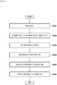
- FIG. 1 a block diagram of FIG. 1 is used to explain an example configuration of a medical image processing system that includes a medical image processing apparatus according to the present embodiment. Note that, as will be explained later, a configuration shown in FIG. 1 is merely one example of a configuration of a medical image processing system to which the present embodiment is applicable, and any configuration may be used if the configuration can realize processing explained below.
- the medical image processing system has a medical image processing apparatus 10 and a database 22, and the medical image processing apparatus 10 and the database 22 are connected to a LAN (Local Area Network) 21.
- LAN Local Area Network
- the medical image processing apparatus 10 and the database 22 may be connected so that communication is possible therebetween; the connection configuration between the medical image processing apparatus 10 and the database 22 is not limited to the LAN 21.
- the database 22 Stored in the database 22 is medical image data for various sites of various patients, various pieces of information corresponding to the medical image data (an imaging target site, an image capturing condition, information corresponding to a patient, or the like), or the like.
- the medical image data includes a plurality of slice images (medical images) of a site that is an imaging target.
- the medical image processing apparatus 10 can read the medical image data saved in the database 22 or various information corresponding to the medical image data.
- the database 22 may be a memory apparatus in the medical image processing apparatus 10, without being an apparatus separate to the medical image processing apparatus 10.
- a communication IF (Interface) 31 is realized by a LAN card or the like, and controls data communication between an external apparatus (for example, the database 22) and the medical image processing apparatus 10 via the LAN 21.
- a ROM (Read Only Memory) 32 is realized by non-volatile memory or the like, and, for example, stores setting data or a boot program for the medical image processing apparatus 10, or the like.
- a RAM (Random Access Memory) 33 is realized by volatile memory or the like, and, for example, has an area for storing a computer program or data loaded from a memory unit 34, or data read from the database 22 via the communication IF 31. Furthermore, a RAM 33 has a work area used when a control unit 37 executes processing. In this way the RAM 33 can appropriately provide various areas.
- the memory unit 34 is a large capacity information storage device realized by an HDD (Hard Disk Drive) or the like. Saved in the memory unit 34, for example, is an OS (operating system), computer programs for causing the control unit 37 to execute or control various processing described later as something the medical image processing apparatus 10 performs, data, or the like. In addition, saved in the memory unit 34 is information handled as information known beforehand in the following explanation. The computer programs, data, or the like saved in the memory unit 34 are loaded into the RAM 33 as appropriate in accordance with control by the control unit 37, and become a target of processing by the control unit 37.
- OS operating system
- An operation unit 35 is realized by a user interface such as a keyboard or a mouse, and by a user of the medical image processing apparatus 10 operating the operation unit 35, various instructions can be input to the control unit 37.
- a display unit 36 is realized by a CRT, a liquid crystal screen, or the like, and can display a result of processing by the control unit 37 through images, text, or the like to thereby enable provision of various information to a user (for example, a doctor).
- the control unit 37 is realized by a CPU (Central Processing Unit) or the like. By using a computer program, data or the like stored in the RAM 33 to execute processing, the control unit 37 performs operation control of the medical image processing apparatus 10 on the whole, and also executes or controls various later-described processing as something that the medical image processing apparatus 10 performs.
- a CPU Central Processing Unit
- the control unit 37 has, as a functional configuration thereof, a data reading unit 41, a target site extraction unit 42, a reference point setting unit 43, a registration unit 44, a movement information calculating unit 45, and a display processing unit 46.
- a functional unit as a subject of processing, but this means that a function of that functional unit is caused to be realized by the control unit 37 executing a computer program corresponding to the functional unit out of computer programs stored in the RAM 33.
- one or more of these functional units may be realized by using dedicated hardware, and software and/or hardware may used in any way to realize these functional units.
- the data reading unit 41 accesses the database 22 via the communication IF 31 or the LAN 21.
- the data reading unit 41 then reads from the database 22 at least two pieces of medical image data (for example, X-ray CT image data captured at times different to each other (X-ray CT image data for different time phases)), which become targets for registration.
- the data reading unit 41 then sends the read medical image data to the target site extraction unit 42 and the registration unit 44.
- medical image data that becomes a reference for registration is referred to as a reference image
- medical image data for which registration is performed with respect to this reference image is referred to as a floating image.
- the target site extraction unit 42 performs processing, which is described later, with respect to at least one piece of the medical image data sent from the data reading unit 41 (for example, the reference image) to thereby acquire outline information, which is information for defining an outline of the target site.
- the outline information may be any information if it is information that can define the outline of the target site on a respective slice image included in the medical image data, but hereinafter, the outline information is information that defines a pixel position (coordinates) for each pixel that configures the outline. However, the outline information may be any information that simply indicates the pixel position of each pixel that configures the outline, and, for example, may be an equation that represents the outline.
- the target site extraction unit 42 then sends the acquired outline information to the reference point setting unit 43.
- the reference point setting unit 43 sets reference points for each of a target-site side (an organ side) and a target site periphery side (a periphery side that faces the organ side) which are across from each other over the outline of the target site.
- the reference point setting unit 43 then sends information indicating a position for each set reference point to the movement information calculating unit 45.
- the registration unit 44 calculates pixel positions in the other piece of medical image data that correspond to respective pixels in the one piece of medical image data.
- the registration unit 44 then sends information indicating the pixel positions in the other piece of medical image data that correspond to the respective pixels in the one piece of medical image data, i.e. information indicating a pixel position correspondence relationship between the pieces of medical image data, as corresponding pixel position information, to the movement information calculating unit 45.
- pixel positions (coordinates) for pixels in the floating image that correspond to pixels that comprise the reference image are corresponding pixel position information.
- the movement information calculating unit 45 uses "information indicating a position of each reference point" sent from the reference point setting unit 43 and the "corresponding pixel position information” sent from the registration unit 44 to execute later described processing, and thereby calculates a "slippage” (a movement amount relative to a periphery) for each pixel (an outline configuration point) that comprises the outline of the target site. The movement information calculating unit 45 then sends the slippage obtained for each outline configuration point to the display processing unit 46.
- the display processing unit 46 displays the "slippage" for each outline configuration point calculated by the movement information calculating unit 45 on the display unit 36.
- Various display forms can be considered for a display form of the "slippage" for each outline configuration point. For example, for one or more slice images included in medical image data, displaying is performed after luminance values of outline configuration points in the slice images are converted to a grayscale value or a color scale value in accordance with the slippage obtained for the outline configuration points.
- control unit 37 may be assigned to an external apparatus (for example, a server apparatus via a network, such as a cloud server) separate to the medical image processing apparatus 10.
- an external apparatus for example, a server apparatus via a network, such as a cloud server
- the medical image processing apparatus 10 advances processing while performing data communication with the external apparatus.
- FIGS. 2 to 4A , 4B are used to give an explanation regarding operation of the medical image processing apparatus 10.
- the data reading unit 41 reads from the database 22 two pieces of medical image data acquired after capturing a chest region for a single patient at two points in time at which inhalation amounts differ by using an X-ray CT apparatus.
- the target site extraction unit 42 sets the target site (organ) for which to extract the outline as a lung, and calculates the "slippage" (slippage of pleura) in relation to the periphery (can also be called parietal pleura) of positions on the surface of the lung (can also be called visceral pleura).
- the periphery can also be called parietal pleura
- visceral pleura can also be called visceral pleura
- the data reading unit 41 accesses the database 22 via the communication IF 31 and the LAN 21, and as described above, reads "two pieces of medical image data acquired after capturing a chest region for a single patient at two points in time at which inhalation amounts differ by using an X-ray CT apparatus" from the database 22.
- the two pieces of medical image data acquired after capturing at two points in time at which inhalation amounts differ are, for example, image data that is for two points in time that are temporally different and is acquired by using a conventional X-ray 4D-CT apparatus to perform capturing without specifying a respiratory condition for a patient (without breath holding).
- the two pieces of medical image data acquired by capturing at two points in time for at which inhalation amounts differ may be two pieces of CT image data captured in a state in which the patient has fully exhaled a breath (exhalation state), and a state in which the breath is fully inhaled (inhalation state).
- step S201 the target site extraction unit 42 extracts a region in a lung field, by a method below, from one of the two pieces of medical image data read by the data reading unit 41 (a reference image), and then acquires outline information of the extracted region (outline information for the lung field).
- the target site extraction unit 42 first uses a smoothing filter to perform noise reduction on the reference image (in other words, each slice image included in the one piece of medical image data of the two pieces of medical image data read by the data reading unit 41 in step S201).
- the target site extraction unit 42 uses a predetermined threshold (for example, -200 HU) to perform binary conversion processing on the reference image on which noise reduction has been performed, to thereby separate regions in the reference image into an inside-body region and an outside-body region.
- the target site extraction unit 42 uses a different threshold (for example, -500 HU) on the inside-body region in the reference image to separate the inside-body region into a region in the lung field and another region, and to obtain a pixel position for each pixel that configures an outline (a boundary of the region in the lung field and the other region) of the region in the lung field According to this type of processing, it is possible to obtain the pixel position for each pixel that configures the outline of the target site in the reference image, i.e. the outline information.
- a different threshold for example, -500 HU
- a region determined from the reference image can be extracted, and limitation is not made to the present approach.
- conventional segmentation processing such as graph cut processing
- diagram drawing software may be used to render the outline for the target site manually by a user, and extract the outline information from the rendered outline.
- the outline information may be extracted after an automatically extracted outline is corrected manually by a user.
- the reference point setting unit 43 uses the outline information acquired by the target site extraction unit 42 to execute the processing explained below and thereby set reference points for each of a target-site side and a target site periphery side which are across from each other over the outline of the target site in the reference image.
- the reference point setting unit 43 sets a first reference point for the target-site side, sets a second reference point for the periphery side that opposes the target-site side from across the outline, and furthermore sets a plurality of first reference point and second reference point pairs.
- movement information for the second reference points is calculated with respect to the first reference points.
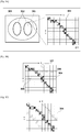
- FIGS. 3A to 3C are used to give an explanation regarding the reference point setting method by the reference point setting unit 43. Note that in FIGS.
- FIGS. 3A to 3C in order to simplify the explanation only a partial region in the reference image is shown, and below such FIGS. 3A to 3C are used to explain a method of setting reference points in the partial region. However, actually similar processing is performed with regards to all regions of the reference image.
- the reference number 302 denotes outlines of regions in a lung field acquired from a chest CT image 301 in step S202.
- the reference number 304 denotes a pixel group in a region 303 shown by broken lines in the chest CT image 301. Boxes filled in black in the pixel group 304 represent pixels that configure the outline 302 in the region 303 (outline configuration points), and boxes filled in white represent pixels that configure a region other than the outline 302 in the region 303.
- the pixel positions (coordinates) for the pixels that comprise the outline 302 become (1,1,1), (2,2,1), (3,2,1), (4,3,1), (5,4,1), (6,5,1), (6,6,1), (7,7,1), (8,8,1), (9,9,1), (9,10,1).
- reference points are set in pairs of the target-site side (in the lung field) and the periphery side (outside the lung field) for all the outline configuration points.
- reference points corresponding to an outline configuration point are set at positions separated by a fixed distance along a normal direction towards each of the target-site side and the periphery side from the center of a line segment connecting two outline configuration points that are adjacent to the outline configuration point (that sandwich the outline configuration point).
- FIGS. 3A to 3C when setting reference points corresponding to the outline configuration point at coordinates (4,3,1), firstly a line segment (reference numeral 305 of FIG.
- a reference point is set at each of a position separated a fixed distance along the normal direction from the center of the line segment 305 to the target-site side, and a position separated a fixed distance along the normal direction from the center of the line segment 305 to the periphery side.
- the "fixed distance” is "two pixels”.
- a pixel 306 and a pixel 307 (in other words a pixel at coordinates (2,5,1) and a pixel at coordinates (6,1,1)) shown with diagonal lines are set as reference points.
- the pixel 306 is a reference point for the target-site side
- the pixel 307 is a reference point for the periphery side.
- FIG. 3C shows a reference point group (the group of boxes shown with diagonal lines) set for all the outline configuration points in the pixel group 304. Note that FIG. 3C shows an example in which reference points corresponding to each outline configuration point included in the pixel group 304 are included in the pixel group 304, but in accordance with the value of the above described "fixed distance" or a distribution of the outline configuration points, there are cases in which a reference point is set outside of the pixel group 304.
- the reference points may be set at any position. For example, they may be set on straight lines extended along the normal directions of the line segment that connects the two outline configuration points adjacent to the focus outline configuration point so as to pass through the focus outline configuration point at positions that are a fixed distance from the focus outline configuration point. Also, in accordance with an orientation of the line segment connecting two outline configuration points that are adjacent to an outline configuration point, the distance by which they are separated from the line segment may be changed.
- reference points may be set both on the outline of the target site, and on either the target-site side or the periphery side of the target site with reference to the outline.
- a reference point of either the target-site side or the periphery side may be the corresponding outline configuration point itself.
- reference points may be set on the outline and on the target-site side (or on the periphery side of the target site).
- the reference point setting unit 43 uses the outline information acquired by the target site extraction unit 42 to set a reference point on each of on the outline of the target site, and either the target-site side and the periphery side of the target site, based on the outline. The reference point setting unit 43 then sends information indicating a position for each set reference point to the movement information calculating unit 45.
- the movement information calculating unit 45 uses the "information indicating the position of each reference point" sent from the reference point setting unit 43 and the "corresponding pixel position information” sent from the registration unit 44 to calculate the movement information for the reference points of the outline and the reference points set in the target-site side (or in the periphery side of the target site).
- the "slippage” (a movement amount relative to the periphery) in each pixel (outline configuration point) that configures the outline of the target site organ is calculated.
- 3A to 3C may be implemented in each slice for the reference image after setting two-dimensional coordinates therein, or three-dimensional coordinates may be set for three-dimensional volume data.
- the reference points may be set for all outline configuration points that configure the outline acquired in step S202 as in the present embodiment, or may be set only for outline configuration points at fixed intervals.
- setting may be performed with respect to only positions on the outline that a user designates.
- the registration unit 44 Towards one (the reference image) of the two pieces of medical image data that the data reading unit 41 read in step S201, the registration unit 44 performs deformation registration of the other piece (the floating image).
- conventional deformation registration processing such as an FFD (Free-Form Deformation) method or an LDDMM (Large Deformation Diffeomorphic Metric Mapping) method, is applicable. Any of such deformation registration maintains a normal structure of the target site in the medical image data.
- non-linear deformation registration processing as initially exemplified above may be performed, but if the difference in inhalation amount is large, deformation registration processing may fail.
- non-linear deformation registration processing may be performed after performing known linear deformation registration processing, such as an affine transformation, before performing non-linear deformation registration processing.
- step S204 may be performed at any time if it is performed after step S201 and before step S205.
- the processing of step S204 may be performed before step S202, and may be performed between step S202 and step S203.
- the processing of step S204 may be performed in parallel with step S202 and step S203.
- the movement information calculating unit 45 calculates movement information for the reference points set on the periphery side with respect to the reference points set on the target-site side, between the medical image for which the reference points are set and the medical image that is registered with respect to the medical image for which the reference points are set.
- the reference points set in step S203 and the corresponding pixel position information acquired in step S204 are used to calculate the "slippage" in each outline configuration point.
- the "slippage" is an amount that the outline configuration point has moved with respect to the periphery.
- FIGS. 4A and 4B are used to specifically explain processing in step S205.
- FIG. 4A shows a pixel group in a partial region of the reference image, in which boxes filled in black, including boxes a-f, indicate outline configuration points (pixels), and boxes filled in white indicate non-outline configuration points (pixels).
- the pixel position for each of the outline configuration points and the non-outline configuration points is shown in an XYZ coordinate system.
- a i -f i each indicate a target-site side reference point corresponding to the outline configuration points a-f
- a o -f o each indicate a periphery side reference point corresponding to the outline configuration points a-f.
- FIG. 4B shows a pixel group in a partial region in the floating image, and the pixel position for each pixel in the pixel group is shown in an X'Y'Z' coordinate system.
- a i - F i respectively indicate pixels defined as pixels that correspond to a i -f i by the corresponding pixel position information
- a o -F o respectively indicate pixels defined as pixels that correspond to a o -f o by the corresponding pixel position information.
- coordinates for a target-site side reference point in the reference image at an outline configuration point P are set as (x i , y i , z i ), and coordinates for a pixel on the floating image corresponding to the reference point are set as (x i ', y i ', z i ').
- coordinates for a periphery side reference point in the reference image at an outline configuration point P are set as (x o , y o , z o )
- coordinates for a pixel on the floating image corresponding to the reference point are set as (x o ', y o ', z o ').
- a "slippage" S (movement information) at the outline configuration point P can be calculated through the following equation.
- S ⁇ x i ⁇ x i ′ ⁇ x o ⁇ x o ′ 2 + y i ⁇ y i ′ ⁇ y o ⁇ y o ′ 2 + z i ⁇ z i ′ ⁇ z o ⁇ z o ′ 2
- the "slippage" S is 0.
- the "slippage" is calculated based on the difference between the pixel positions of the reference points set for the outline configuration points, and the pixel positions of the points defined by the corresponding pixel position information as points on the floating image that correspond to the reference points. Note that if in step S203 reference points are only set for a portion of outline configuration points from outline configuration point group, the "slippage" is only calculated for the outline configuration points for which reference points are set.
- the display processing unit 46 visualizes and displays on the display unit 36 the slippage. In other words, as described above, the display processing unit 46 displays the "slippage" for each outline configuration point calculated by the movement information calculating unit 45 on the display unit 36.
- the color scale or grayscale may be predetermined, or may be changed dynamically. For example, the width of the grayscale and the median value thereof may be determined from a minimum value and a maximum value from the respective slippages calculated in step S205.
- the visualization method for the "slippage"s described here is merely an example, and the visualization method is not limited to this if a position-within-target-site of the target site and the "slippage" at its position can be displayed in association.
- the luminances of the outline configuration points in a portion of the slice images may be converted to grayscale values or color scale values in accordance with the slippages obtained for those outline configuration points, and these may be displayed.
- This "a portion of the slice images” may be slice images selected by a user operating the operation unit 35, or may be slice images selected by the control unit 37 on the basis of some criteria.
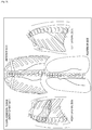
- FIG. 5 is a view in which, for a patient having adhesion in a pleura, a mark is entered at a position at which a respiratory surgery department doctor could visually observe the adhesion when an open-chest operation is actually performed. According to FIG. 5 , it is seen that the adhesion for this patient is in a wide range from the right side between the third-fifth ribs slightly towards a rearward direction.
- FIGS. 6A and 6B are views that visualize "slippage" using the approach in the present embodiment with respect to an X-ray 4D-CT image for the same patient as FIG. 5 before the operation.
- FIG. 5 is a view in which, for a patient having adhesion in a pleura, a mark is entered at a position at which a respiratory surgery department doctor could visually observe the adhesion when an open-chest operation is actually performed. According to FIG. 5 , it is seen that the adhesion for this patient is in a wide range from the right side between the third-fifth
- FIG. 6A is a view of a 3D image that visualizes the "slippage” in the present embodiment from the perspective of the right lateral side of the patient
- FIG. 6B is a view from the perspective of a left lateral side.
- the "slippage" is shown in a grayscale, and closer to white indicates a region for which the "slippage” is higher (more slippage), and closer to black indicates a region for which the "slippage” is lower (does not slip as much).
- focusing on a region 601 of FIG. 6A it is rendered as relatively black in comparison to the periphery thereof. This is more noticeable when compared to the same position of FIG. 6B , on the opposite side.
- Positions rendered as relatively black in the region 601 is substantially the same as the adhesion positions of the pleura shown in FIG. 5 . Furthermore, when a respiratory surgery department doctor and a radiation department doctor who are medical specialists in interpretation confirm the images of FIGs. 6A and 6B , a conclusion that it is possible to visualize approximately the same region from an anatomical structure of the periphery was reached. From these results, it can be said that it is actually possible to visualize the adhesion position of the pleura in the approach in the present embodiment. Accordingly, because the position of adhesion is known from the imaged medical image data before the operation, there is the effect that it is possible to avoid unnecessary risk when performing an operation.
- a user can recognize the position-within-target-site that has "slippage” that is different to the periphery, and can recognize the existence/absence of an abnormality of a target site, a position of an abnormality, or the like.
- step S201 of the first embodiment two pieces of medical image data acquired after capturing at two point in times at which the inhalation amount is different are read.
- the number of pieces of the medical image data read in step S201 may be three or more.
- configuration may be performed to use the X-ray 4D-CT apparatus in a state in which the patient does not stop respiration to read from the database 22 medical image data that is for many points in time and is captured at a specific interval.
- FIGS. 7A-7D , 8 are used to explain the medical image data for many points in time.
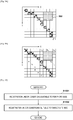
- FIGS. 7A, 7B, 7C, 7D show slice images (medical images) (portion) in medical image data captured at points in time T1, T2, T3, and Tn (n is an integer greater than or equal to 4), respectively, and pixel positions in the medical image data are expressed by an XYZ coordinate system.
- T1 is the considered as a reference.
- extraction of the outline of the target site in step S202 or setting of the reference points in step S203 is performed with respect to the medical image data captured at the point in time T1.
- a point in time other than T1 may be the reference.
- T1i is a reference point (the coordinates thereof are (2,5,1)) of the target-site side corresponding to an outline configuration point (an outline configuration point Q), and T1o is a reference point (the coordinates thereof are (3,2,1)) of the periphery side corresponding to the outline configuration point Q.
- T2i and T2o are corresponding points defined as points that correspond to T1i and T1o, respectively, by corresponding pixel position information acquired by performing the above-described deformation registration on medical image data that includes the slice image of FIG. 7A as the reference image and medical image data that includes the slice image of FIG. 7B as the floating image.
- Coordinates of point T2i are (4,5,1), and coordinates of point T2o are (4,1,1).
- the slippage S of the outline configuration point Q, acquired by substituting coordinates of the reference points T1i and T1o and coordinates of T2i and T2o into the above-described equation, is "2".
- T3i and T3o are corresponding points defined as points that correspond to T1i and T1o, respectively, by corresponding pixel position information acquired by performing the above-described deformation registration on medical image data that includes the slice image of FIG. 7A as the reference image and medical image data that includes the slice image of FIG. 7C as the floating image.
- Coordinates of point T3i are (5,5,1)
- coordinates of point T3o are (4,1,1).
- the slippage S of the outline configuration point Q acquired by substituting coordinates of the reference points T1i and T1o and coordinates of T3i and T3o into the above-described equation, is "5".
- Tni and Tno are corresponding points defined as points that correspond to T1i and T1o, respectively, by corresponding pixel position information acquired by performing the above-described deformation registration on medical image data that includes the slice image of FIG. 7A as the reference image and medical image data that includes the slice image of FIG. 7D as the floating image.
- Coordinates of point Tni are (2,5,1)
- coordinates of point Tno are (2,1,1).
- the slippage S of the outline configuration point Q acquired by substituting coordinates of the reference points T1i and T1o and coordinates of Tni and Tno into the above-described equation, is "2".
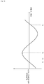
- step S205 for each outline configuration point, a portion or all of the "slippage" at each point in time obtained for the outline configuration point is used to calculate a "second slippage" for the outline configuration point. For example, an average value across all points in time of the "slippage"s of the respective point in time may be set as the "second slippage", or a maximum value of the "slippage" across all points in time may be set as the "second slippage”.
- the "slippage" for a reference point in time (T1 in the present example) in the respective points in time also changes periodically as in FIG. 8 .
- the amplitude or period of the periodic function is used to calculate the "second slippage".
- step S206 of the present variation the display processing unit 46 performs processing similar to that of the first embodiment so as to visualize the "second slippage".
- luminances of outline configuration points in the medical image data are converted to grayscale values or color scale values in accordance with the "second slippage" obtained for the outline configuration points, and the post-conversion medical image data is displayed.
- the method of calculating the "second slippage” explained here is one example, and the method of calculating the “second slippage” is not limited to this if it can use the "slippage"s of a plurality of points of time to represent a relative movement amount with respect to the periphery of each position-within-target-site in the target site.
- step S204 two differing pieces of medical image data are used to perform deformation registration.
- medical image data for a plurality of points in time may be used to gradually perform registration of the reference image and the floating image, and to calculate the "slippage".
- FIGS. 7A-7D are used to explain the present variation.
- the medical image data that includes the slice image shown in FIG. 7A is set as the reference image
- the medical image data that includes the slice image shown in FIG. 7D is set as the floating image.
- the medical image data that includes the slice image of FIG. 7A , the medical image data that includes the slice image of FIG. 7B , the medical image data that includes the slice image of FIG. 7C , and the medical image data that includes the slice image of FIG. 7D are captured in a temporal sequence in this order (in other words T1 ⁇ T2 ⁇ T3 ⁇ Tn).
- the reference image and the medical image data of point in time T2 adjacent thereto are used to perform deformation registration (called deformation processing 1), and to calculate the points T2i and T2o, on the medical image data that includes the slice image of FIG. 7B , corresponding to each of the reference points T1i and T1o.
- the medical image data that includes the slice image of FIG. 7B , and the medical image data (the medical image data that includes the slice image of FIG. 7C ) of a point in time that is a point in time adjacent thereto and that is a point in time (T3 in the case of FIGS. 7A-7D ) closer to the point in time Tn are used to perform deformation registration.
- points T3i and T3o, on the medical image data of FIG. 7C corresponding to each of the reference points T2i and T2o are calculated.
- the "slippage" is calculated by using a reference image which is the medical image data of the point in time T1, and the floating image which is the medical image data of the point in time Tn. If the above-described equation is calculated by using the coordinates of T1i (2,5,1) and the coordinates of Tni (2,5,1) as well as the coordinates of T1o (3,2,1) and the coordinates of Tno (2,1,1), 2 is calculated as the "slippage".
- the corresponding pixel position information is acquired from a result of deformation registration processing with respect to the reference image and the floating image, which have the same image condition.
- the deformation registration processing may be performed to acquire the corresponding pixel position information after changing the image condition of the reference image and the floating image in accordance with the position of a reference point.
- registration may be performed between medical images (medical image data) that are a target of registration, after correcting the medical images that are the target of registration in accordance with an image condition corresponding to a position at which a reference point is set.
- This image condition differs for a position of a reference point of the target-site side, and a position of a reference point of the periphery side of the target site.
- the target site is a lung.
- density values of the reference image and the floating image are set to conditions suitable to observation of a lung field (for example, WL at -600, WW at 1500), deformation registration processing is performed, and acquisition is performed using the result thereof.
- step S204 for a position of a point on the floating image corresponding to the reference point of the periphery side, density values of the reference image and the floating image are set to conditions suitable to observation of a mediastinum (for example, WL at 60, WW at 400), deformation registration processing is then performed, and acquisition is performed using the result thereof. Then in step S205, for each reference point, the corresponding pixel position information acquired under the suitable image condition is used to calculate the "slippage".
- a mediastinum for example, WL at 60, WW at 400
- image characteristics of the medical image data also differs. If deformation registration processing is performed collectively for such regions having differing medical image data image characteristics, there may be a failure.
- suitable image conditions are used for each of regions in which characteristics of the medical image data differ to perform the deformation registration processing. Thereby, it is possible to perform correct deformation registration processing with respect to each region. Accordingly, there is the effect that even if reference points are set with respect to regions for which characteristics of the medical image data differs, it is possible to calculate the corresponding pixel position information correctly with respect to each reference point.
- step S203 reference points for an outline configuration point are set at positions separated by a fixed distance along normal directions from the center of a line segment connecting two outline configuration points adjacent to the outline configuration point.
- an anatomical structure in the medical image data may be used to intentionally set a region (hereinafter referred to as an exclusion region) in which reference points are not set.
- a region hereinafter referred to as an exclusion region
- a bone region, a blood vessel region, or the like may be set as an exclusion region.
- the exclusion region which is a region in which reference points are not set, is acquired from the medical image (medical image data), and the reference points are set outside the exclusion region in the medical image.
- a bone region is acquired as the exclusion region and the reference points are set outside the exclusion region is explained as an example.
- a known segmentation method such as graph cut processing, is used to extract the bone region in the body from the medical image data.
- an approach for extracting the bone region is not limited to this, and configuration may be taken so that: the medical image data is displayed on the display unit 36; a user operates the operation unit 35, while watching the medical image data that is displayed, to manually select the bone region; and the selected bone region is thereby extracted.
- FIGs. 9A and 9B are used to explain details for this reference point setting method.
- FIG. 9A shows a state in which a bone region 902 is included in the pixel group 304.
- the pixel positions of each pixel that configures the bone region 902 are (7,2,1), (8,2,1), (9,2,1), (7,3,1), (8,3,1), (9,3,1), (7,4,1), (8,4,1), (9,4,1).
- Explanation is given for a case in which in such a state, as the method of setting the reference points of the outline configuration points, a method of setting at positions for which a distance separated from the center of a line segment connecting two outline configuration points adjacent to the outline configuration point and along a normal direction is just two pixels is employed.
- step S203 the coordinates of a target-site side reference point become (2,5,1), and coordinates of a periphery side reference point become (6,1,1) for the position of a point a in FIGS. 9A and 9B .
- Next reference points for the position of a point b is considered.
- the coordinate of the target-site side reference point become (3,6,1)
- coordinates of the periphery side reference point become (7,2,1) for the position of a point b
- coordinates (7,2,1) are coordinates that are inside the bone region.
- a position further separated by just one pixel along the normal direction is re-set as the position of the reference point.
- the periphery side reference point for the position of the point b is set at the coordinates (8,1,1).
- setting is performed to a position further separated by one pixel.
- the position set for the reference point is changed to a position separated along a normal direction.
- FIG. 9B shows target-site side reference points ai-fi and periphery side reference points ao-fo for positions of points a-f in FIGS. 9A and 9B .
- a reference point for an outline configuration point is set at a position separated by a fixed distance or more (for example, 50 pixels or more), it may not be possible to calculate a "slippage" that meets the intention of a user. Accordingly, if a reference point is set to a position that is separated by a predetermined fixed distance or more, configuration may be taken to not calculate a "slippage" for the outline configuration point corresponding to that reference point.
- a fixed distance or more for example, 50 pixels or more
- step S205 the reference points set in step S203 and the corresponding pixel position information acquired in step S204 are used to calculate the "slippage" for each the outline configuration point.
- other information may be used. For example, in a normal state for the lungs, the caudal side thereof (close to the diaphragm) has a large movement amount in comparison to the cranial side thereof (close to the apex pulmonis), and in other words has a large "slippage". Accordingly, if the magnitude of the "slippage” is simply visualized, there is the possibility that recognition of a region having an abnormal "slippage" will become difficult.
- a model reflecting movement of a normal lung is generated, and the model may be used to obtain a correction coefficient for "slippage" of the caudal side region and of the cranial side region, and applied to the "slippage" of each outline configuration point.
- the slippage obtained for each position on the surface of the target site or for each position in the target site may be corrected by using a correction coefficient set for each position on the surface of the target site or of for each position in the target site.
- a correction coefficient that reduces the "slippage” is calculated, and for a region in which the "slippage" is small in a normal state (for example, the cranial side region), a correction coefficient that enlarges the "slippage” is calculated. Then the movement information calculating unit 45 uses the calculated correction coefficients to normalize (correct) the "slippage" for each outline configuration point (for example, the "slippage” is multiplied by the correction coefficient). Thereby, it is possible to calculate "slippage" that better matches the intention of a user.
- the method of normalizing the "slippage" for each outline configuration point based on normal movement of the target site is just one example, and other methods may be used to achieve a similar objective.
- normalizing may be performed by using medical image data temporally captured in the past for the same patient. At that time, it is possible to visualize a region in which a difference in "slippage" is large with respect to the past.
- the "slippage" of the symmetrical target site of the target site may be used to perform normalizing.
- step S202-step S206 may be performed with respect to these two pieces of medical image data.
- a conventional rib extraction method may be used to remove the rib region from the medical image data, and thereafter conventional segmentation processing may be used to extract the lung field.
- reference points are set on the target-site side and the periphery side across from each other over an outline for each outline configuration point of the target site, and the "slippage" is calculated based on corresponding pixel position information for each reference point.
- the outside (the periphery side) of the outline of the target site is fixed, and the "slippage" is calculated from the corresponding pixel position information of each reference point in the inside (the target-site side).
- step S201-step S203 is similar to the processing in the first embodiment.
- step S204 processing in accordance with the flowchart of FIG. 10 is performed.
- the registration unit 44 performs the deformation registration processing after setting the density value for each of the reference image and the floating image to conditions (for example, WL as 60 and WW as 400) suitable to the display of the periphery side (a soft part region, such as muscle or the like).
- a provisional image an image generated by performing the deformation registration processing on the reference image with respect to the floating image under conditions suitable to display of the periphery side.
- the registration unit 44 performs the deformation registration processing after setting the density value for each of the reference image and the provisional image to conditions (for example, WL as -600 and WW as 150) suitable to the display of the target site (organ side: the lung field region). Then the registration unit 44 calculates the pixel positions on the provisional image corresponding to respective pixels on the reference image (acquires the corresponding pixel position information).
- the positions of periphery side reference points on the reference image and positions of corresponding points on the provisional image, which correspond to the reference points, should substantially match by the processing of step S1001.
- the target-site side reference points for respective outline configuration points corresponding to position having adhesion also substantially match by the processing of step S1001, similar to the periphery side reference points.
- the "slippage" of the target-site side reference points for respective outline configuration points corresponding to positions at which there is adhesion becomes smaller in comparison to a position at which there is no adhesion.
- step S205 the movement information calculating unit 45 uses the target-site side reference points from the reference points set in step S203, and the corresponding pixel position information for the target-site side reference points, from the corresponding pixel position information acquired in step S204, to calculate the "slippage" for each outline configuration point.
- the corresponding pixel position information for the periphery side reference points is not used. More specifically, coordinates for a target-site side reference point in the reference image at an outline configuration point P are set as (x i , y i , z i ), and coordinates for a pixel on the provisional image corresponding to the reference point are set as (x i ', y i ', z i ').
- step S206 is similar to that of the first embodiment.
- a user can recognize a region having "slippage” that is different to the periphery of the target site, and can recognize the presence/absence of an abnormality of the target site, the position of an abnormal location, or the like.
- the above-explained embodiments and variations may be implemented by appropriately combining all or parts thereof.
- each of the first and second embodiments and the first-sixth variations is merely an example of a medical image processing apparatus comprising: an acquisition unit that acquires medical image data for of differing time phases, an extraction unit that extracts a target site with respect to at least one piece of the medical image data acquired in accordance with the acquisition unit, a setting unit for respectively setting a reference point on an outline of the target site extracted by the extraction unit, and setting a reference point on either a target-site side or a periphery side of the target site, making the outline a reference, and a movement information calculating unit that calculates movement information for the reference point set by the setting unit, and further variations can be considered if they have a configuration that resolves to a similar configuration.
- Embodiment(s) of the present invention can also be realized by a computer of a system or apparatus that reads out and executes computer executable instructions (e.g., one or more programs) recorded on a storage medium (which may also be referred to more fully as a 'non-transitory computer-readable storage medium') to perform the functions of one or more of the above-described embodiment(s) and/or that includes one or more circuits (e.g., application specific integrated circuit (ASIC)) for performing the functions of one or more of the above-described embodiment(s), and by a method performed by the computer of the system or apparatus by, for example, reading out and executing the computer executable instructions from the storage medium to perform the functions of one or more of the above-described embodiment(s) and/or controlling the one or more circuits to perform the functions of one or more of the above-described embodiment(s).
- computer executable instructions e.g., one or more programs
- a storage medium which may also be referred to more fully as
- the computer may comprise one or more processors (e.g., central processing unit (CPU), micro processing unit (MPU)) and may include a network of separate computers or separate processors to read out and execute the computer executable instructions.
- the computer executable instructions may be provided to the computer, for example, from a network or the storage medium.
- the storage medium may include, for example, one or more of a hard disk, a random-access memory (RAM), a read only memory (ROM), a storage of distributed computing systems, an optical disk (such as a compact disc (CD), digital versatile disc (DVD), or Blu-ray Disc (BD)TM), a flash memory device, a memory card, and the like.
Landscapes
- Engineering & Computer Science (AREA)
- Theoretical Computer Science (AREA)
- Computer Vision & Pattern Recognition (AREA)
- Physics & Mathematics (AREA)
- General Physics & Mathematics (AREA)
- Health & Medical Sciences (AREA)
- General Health & Medical Sciences (AREA)
- Medical Informatics (AREA)
- Nuclear Medicine, Radiotherapy & Molecular Imaging (AREA)
- Radiology & Medical Imaging (AREA)
- Quality & Reliability (AREA)
- Multimedia (AREA)
- Apparatus For Radiation Diagnosis (AREA)
Claims (12)
- Vorrichtung (10) zum Verarbeiten medizinischer Bilder, umfassend:eine Erfassungseinrichtung (41) zum Erfassen von mehreren medizinischen Bildern in Zeitphasen;eine Extraktionseinrichtung (42) zum Extrahieren eines Zielortes aus mindestens einem medizinischen Bild aus den mehreren medizinischen Bildern;eine Einstelleinrichtung (43) zum Einstellen von mehreren Paaren aus einem ersten Referenzpunkt (306) auf einer Zielortseite und einem zweiten Referenzpunkt (307) auf einer Umgebungsseite des Zielortes, wobei die Umgebungsseite und die Zielortseite sich auf verschiedenen Seiten des Umrisses des durch die Extraktionseinrichtung extrahierten Zielortes gegenüberliegen;eine Berechnungseinrichtung (45) zum Berechnen von mehreren Verschiebungen für die mehreren Paare basierend auf Bewegungsinformationen des zweiten Referenzpunktes (307) in Bezug auf den ersten Referenzpunkt (306); undeine Anzeigeverarbeitungseinrichtung (46) zum Anzeigen des medizinischen Bilds mit den mehreren Verschiebungen, die den mehreren Paaren des ersten Referenzpunktes (306) und des zweiten Referenzpunktes (307) entsprechen, auf einer Anzeigeeinrichtung (36).
- Vorrichtung zum Verarbeiten medizinischer Bilder nach Anspruch 1, wobei die Berechnungseinrichtung (45) eine Verschiebung des Zielortes in Bezug auf die Umgebung des Zielortes basierend auf den mehreren Verschiebungen für die mehreren Paare berechnet.
- Vorrichtung zum Verarbeiten medizinischer Bilder nach Anspruch 2, ferner umfassend die Anzeigeeinrichtung (36).
- Vorrichtung zum Verarbeiten medizinischer Bilder nach einem der Ansprüche 1 bis 3, ferner umfassend:eine Registrierungseinrichtung (44) zum Durchführen einer Registrierung zwischen medizinischen Bildern unterschiedlicher Zeitphasen,wobei die Berechnungseinrichtung (45) die mehreren Verschiebungen basierend auf Bewegungsinformation des zweiten Referenzpunktes (307) in Bezug auf den ersten Referenzpunkt (306) zwischen dem medizinischen Bild, in dem die Einstelleinrichtung (43) die Referenzpunkte einstellt, und einem durch die Registrierungseinrichtung registrierten medizinischen Bild in Bezug auf dieses medizinische Bild berechnet.
- Vorrichtung zum Verarbeiten medizinischer Bilder nach Anspruch 4, wobei die Registrierungseinrichtung (44) eine Deformationsregistrierung durchführt, die eine normale Struktur eines Zielortes in einem medizinischen Bild aufrechterhält.
- Vorrichtung zum Verarbeiten medizinischer Bilder nach Anspruch 4 oder 5, wobei die Registrierungseinrichtung (44) eine Registrierung zwischen medizinischen Bildern durchführt, die Ziele zur Registrierung sind, nach dem Korrigieren der medizinischen Bilder, die Ziele für die Registrierung sind, gemäß einer Bildbedingung, die einer Position entspricht, an der die Einstelleinrichtung (43) die mehreren Paare der ersten und zweiten Referenzpunkte einstellt.
- Vorrichtung zum Verarbeiten medizinischer Bilder nach Anspruch 6, wobei sich die Bildbedingung für die Position des ersten Referenzpunktes (306) und für die Position des zweiten Referenzpunktes (307) unterscheidet.
- Vorrichtung zum Verarbeiten medizinischer Bilder nach Anspruch 2, wobei die Berechnungseinrichtung (45) die für eine jeweilige Position im Zielort oder für eine jeweilige Position auf einer Oberfläche des Zielortes erhaltene Verschiebung unter Verwendung eines für eine jeweilige Position im Zielort oder für eine jeweilige Position auf der Oberfläche des Zielortes eingestellten Korrekturkoeffizienten korrigiert.
- Vorrichtung zum Verarbeiten medizinischer Bilder nach Anspruch 2, wobei das medizinische Bild durch eine Röntgen-4D-CT-Vorrichtung aufgenommen wird, der Zielort eine Lunge ist und die Berechnungseinrichtung die Verschiebung eines Brustfells berechnet.
- Vorrichtung zum Verarbeiten medizinischer Bilder nach einem der Ansprüche 1 bis 9, ferner umfassend:eine Einrichtung zum Erfassen einer Ausschlussregion, die eine Region im medizinischen Bild ist, in der kein Referenzpunkt eingestellt ist,wobei die Einstelleinrichtung (43) die mehreren Paare der ersten und zweiten Referenzpunkte im medizinischen Bild außerhalb der Ausschlussregion einstellt.
- Verfahren zum Verarbeiten medizinischer Bilder, umfassend:einen Erfassungsschritt (S201) zum Erfassen von mehreren medizinischen Bildern in Zeitphasen;einen Extraktionsschritt (S202) zum Extrahieren eines Zielortes aus mindestens einem medizinischen Bild aus den mehreren medizinischen Bildern;einen Einstellschritt (S203) zum Einstellen von mehreren Paaren aus einem ersten Referenzpunkt (306) auf einer Zielortseite und einem zweiten Referenzpunkt (307) auf einer Umgebungsseite des Zielortes, wobei die Umgebungsseite und die Zielortseite sich auf verschiedenen Seiten des Umrisses des im Extraktionsschritt extrahierten Zielortes gegenüberliegen;einen Berechnungsschritt (S205) zum Berechnen, basierend auf Bewegungsinformation des zweiten Referenzpunktes (307) in Bezug auf den ersten Referenzpunkt (306), von mehreren Verschiebungen für die mehreren Paare; undeinen Anzeigeschritt (S206) zum Anzeigen des medizinischen Bilds mit den mehreren Verschiebungen, die den mehreren Paaren aus dem ersten Referenzpunkt (306) und dem zweiten Referenzpunkt (307) entsprechen.
- Computerprogramm um einen Computer zu veranlassen, zu funktionieren als:eine Erfassungseinrichtung (41) zum Erfassen von mehreren medizinischen Bildern in Zeitphasen;eine Extraktionseinrichtung (42) zum Extrahieren eines Zielortes aus mindestens einem medizinischen Bild aus den mehreren medizinischen Bildern;eine Einstelleinrichtung (43) zum Einstellen von mehreren Paaren aus einem ersten Referenzpunkt (306) auf einer Zielortseite und einem zweiten Referenzpunkt (307) auf einer Umgebungsseite des Zielortes, wobei die Umgebungsseite und die Zielortseite sich auf verschiedenen Seiten des Umrisses des durch die Extraktionseinrichtung extrahierten Zielortes gegenüberliegen;eine Berechnungseinrichtung (45) zum Berechnen, basierend auf Bewegungsinformation des zweiten Referenzpunktes (307) in Bezug auf den ersten Referenzpunkt (306), von mehreren Verschiebungen für die mehreren Paare; undeine Anzeigeverarbeitungseinrichtung (46) zum Anzeigen des medizinischen Bilds mit den mehreren Verschiebungen, die den mehreren Paaren des ersten Referenzpunktes (306) und des zweiten Referenzpunktes (307) entsprechen, auf einer Anzeigeeinrichtung (36).
Applications Claiming Priority (2)
| Application Number | Priority Date | Filing Date | Title |
|---|---|---|---|
| JP2014203344A JP6532206B2 (ja) | 2014-10-01 | 2014-10-01 | 医用画像処理装置、医用画像処理方法 |
| PCT/JP2015/004581 WO2016051683A1 (en) | 2014-10-01 | 2015-09-09 | Medical image processing apparatus, medical image processing method |
Publications (2)
| Publication Number | Publication Date |
|---|---|
| EP3201876A1 EP3201876A1 (de) | 2017-08-09 |
| EP3201876B1 true EP3201876B1 (de) | 2021-06-23 |
Family
ID=54292874
Family Applications (1)
| Application Number | Title | Priority Date | Filing Date |
|---|---|---|---|
| EP15778764.9A Active EP3201876B1 (de) | 2014-10-01 | 2015-09-09 | Vorrichtung zur verarbeitung medizinischer bilder, verfahren zur verarbeitung medizinischer bilder |
Country Status (4)
| Country | Link |
|---|---|
| US (4) | US10475184B2 (de) |
| EP (1) | EP3201876B1 (de) |
| JP (1) | JP6532206B2 (de) |
| WO (1) | WO2016051683A1 (de) |
Families Citing this family (11)
| Publication number | Priority date | Publication date | Assignee | Title |
|---|---|---|---|---|
| JP6565422B2 (ja) * | 2015-07-24 | 2019-08-28 | 富士通株式会社 | 画像処理プログラム、画像処理装置及び画像処理方法 |
| JP6833444B2 (ja) | 2016-10-17 | 2021-02-24 | キヤノン株式会社 | 放射線撮影装置、放射線撮影システム、放射線撮影方法、及びプログラム |
| US11138735B2 (en) | 2017-10-17 | 2021-10-05 | Canon Medical Systems Corporation | Image processing apparatus and medical image taking apparatus |
| US11151726B2 (en) * | 2018-01-10 | 2021-10-19 | Canon Medical Systems Corporation | Medical image processing apparatus, X-ray diagnostic apparatus, and medical image processing method |
| WO2020138136A1 (ja) * | 2018-12-27 | 2020-07-02 | キヤノン株式会社 | 画像処理装置、画像処理方法及びプログラム |
| JP7556715B2 (ja) * | 2020-07-27 | 2024-09-26 | キヤノン株式会社 | 情報処理装置、情報処理方法、及びプログラム |
| JP7500360B2 (ja) * | 2020-09-11 | 2024-06-17 | キヤノン株式会社 | 情報処理装置、情報処理方法、及びプログラム |
| US12193759B2 (en) * | 2020-12-30 | 2025-01-14 | Canon U.S.A., Inc. | Real-time correction of regional tissue deformation during endoscopy procedure |
| JP7643875B2 (ja) | 2021-01-15 | 2025-03-11 | キヤノン株式会社 | 情報処理装置、情報処理方法、及びプログラム |
| JP7052103B2 (ja) * | 2021-02-01 | 2022-04-11 | キヤノン株式会社 | 放射線撮影装置、放射線撮影システム、放射線撮影方法、及びプログラム |
| JP7707588B2 (ja) | 2021-03-17 | 2025-07-15 | コニカミノルタ株式会社 | 動態画像解析装置及びプログラム |
Family Cites Families (19)
| Publication number | Priority date | Publication date | Assignee | Title |
|---|---|---|---|---|
| JP3577680B2 (ja) * | 1995-04-27 | 2004-10-13 | コニカミノルタホールディングス株式会社 | 画像処理装置 |
| EP1208796B1 (de) * | 2000-11-22 | 2003-03-05 | BrainLAB AG | Verfahren zur Bestimmung der Lungenfüllung |
| CN101166470B (zh) * | 2005-04-28 | 2016-04-06 | 株式会社日立医药 | 图像显示装置及图像显示方法 |
| JP4751282B2 (ja) * | 2006-09-27 | 2011-08-17 | 株式会社日立製作所 | 超音波診断装置 |
| JP2010069099A (ja) * | 2008-09-19 | 2010-04-02 | Toshiba Corp | 画像処理装置及びx線コンピュータ断層撮影装置 |
| JP5737858B2 (ja) | 2010-04-21 | 2015-06-17 | キヤノン株式会社 | 画像処理装置、画像処理方法、及びプログラム |
| JP5872323B2 (ja) | 2011-03-29 | 2016-03-01 | 株式会社東芝 | X線ct装置及び画像処理方法 |
| JP5685133B2 (ja) | 2011-04-13 | 2015-03-18 | キヤノン株式会社 | 画像処理装置、画像処理装置の制御方法、およびプログラム |
| JP5858636B2 (ja) | 2011-04-13 | 2016-02-10 | キヤノン株式会社 | 画像処理装置、その処理方法及びプログラム |
| US10049445B2 (en) | 2011-07-29 | 2018-08-14 | Canon Kabushiki Kaisha | Image processing apparatus and image processing method of a three-dimensional medical image |
| JP5995449B2 (ja) | 2012-01-24 | 2016-09-21 | キヤノン株式会社 | 情報処理装置及びその制御方法 |
| JP6039903B2 (ja) | 2012-01-27 | 2016-12-07 | キヤノン株式会社 | 画像処理装置、及びその作動方法 |
| CN104703539B (zh) * | 2012-10-04 | 2018-04-10 | 柯尼卡美能达株式会社 | 图像处理装置和程序 |
| US20160117797A1 (en) * | 2013-06-06 | 2016-04-28 | Hitachi, Ltd. | Image Processing Apparatus and Image Processing Method |
| WO2015029571A1 (ja) | 2013-08-29 | 2015-03-05 | 三菱瓦斯化学株式会社 | 多層構造体 |
| JP6431342B2 (ja) | 2014-01-16 | 2018-11-28 | キヤノン株式会社 | 画像処理装置、画像処理方法およびプログラム |
| JP6489800B2 (ja) | 2014-01-16 | 2019-03-27 | キヤノン株式会社 | 画像処理装置、画像診断システム、画像処理方法およびプログラム |
| JP6489801B2 (ja) | 2014-01-16 | 2019-03-27 | キヤノン株式会社 | 画像処理装置、画像診断システム、画像処理方法およびプログラム |
| JP6397277B2 (ja) | 2014-09-05 | 2018-09-26 | キヤノン株式会社 | 読影レポート作成のための支援装置およびその制御方法 |
-
2014
- 2014-10-01 JP JP2014203344A patent/JP6532206B2/ja active Active
-
2015
- 2015-09-09 US US15/514,140 patent/US10475184B2/en active Active
- 2015-09-09 EP EP15778764.9A patent/EP3201876B1/de active Active
- 2015-09-09 WO PCT/JP2015/004581 patent/WO2016051683A1/en not_active Ceased
-
2019
- 2019-09-30 US US16/588,015 patent/US11176671B2/en active Active
-
2021
- 2021-10-14 US US17/501,477 patent/US11676277B2/en active Active
-
2023
- 2023-04-28 US US18/309,507 patent/US20230267613A1/en active Pending
Non-Patent Citations (1)
| Title |
|---|
| None * |
Also Published As
| Publication number | Publication date |
|---|---|
| JP6532206B2 (ja) | 2019-06-19 |
| US20200043169A1 (en) | 2020-02-06 |
| US20170309026A1 (en) | 2017-10-26 |
| US20230267613A1 (en) | 2023-08-24 |
| JP2016067832A (ja) | 2016-05-09 |
| US11176671B2 (en) | 2021-11-16 |
| WO2016051683A1 (en) | 2016-04-07 |
| EP3201876A1 (de) | 2017-08-09 |
| US10475184B2 (en) | 2019-11-12 |
| US11676277B2 (en) | 2023-06-13 |
| US20220036557A1 (en) | 2022-02-03 |
Similar Documents
| Publication | Publication Date | Title |
|---|---|---|
| US11676277B2 (en) | Medical image processing apparatus and method | |
| JP5643304B2 (ja) | 胸部トモシンセシスイメージングにおけるコンピュータ支援肺結節検出システムおよび方法並びに肺画像セグメント化システムおよび方法 | |
| EP4102461A2 (de) | Verfahren und vorrichtung zur registrierung medizinischer bilder | |
| US10867423B2 (en) | Deformation field calculation apparatus, method, and computer readable storage medium | |
| US10692198B2 (en) | Image processing apparatus, image processing method, image processing system, and non-transitory computer-readable storage medium for presenting three-dimensional images | |
| JP2016539701A (ja) | 三次元(3d)プレスキャンに基づく体積画像データ処理 | |
| US9269165B2 (en) | Rib enhancement in radiographic images | |
| US11836923B2 (en) | Image processing apparatus, image processing method, and storage medium | |
| JP2016116867A (ja) | 医用画像処理装置、医用画像診断装置及び医用画像処理プログラム | |
| CN108430376B (zh) | 提供投影数据集 | |
| US11138736B2 (en) | Information processing apparatus and information processing method | |
| JP6747785B2 (ja) | 医用画像処理装置及び医用画像処理方法 | |
| JP2019531774A (ja) | モデル正規化動き補償医用画像再構成 | |
| US20220092745A1 (en) | Information processing apparatus, information processing method, and non-transitory recording medium | |
| US11257219B2 (en) | Registration of static pre-procedural planning data to dynamic intra-procedural segmentation data | |
| JP2004152043A (ja) | 差分画像の補正方法および画像処理装置 | |
| JP7015351B2 (ja) | 医用画像処理装置、医用画像処理方法 | |
| JP6748762B2 (ja) | 医用画像処理装置、医用画像処理方法 | |
| US20250209619A1 (en) | Image processing apparatus, image processing method, and computer program | |
| JP2023080703A (ja) | 医用画像処理装置、方法及びプログラム | |
| WO2010134013A1 (en) | Interactive image registration |
Legal Events
| Date | Code | Title | Description |
|---|---|---|---|
| STAA | Information on the status of an ep patent application or granted ep patent |
Free format text: STATUS: THE INTERNATIONAL PUBLICATION HAS BEEN MADE |
|
| PUAI | Public reference made under article 153(3) epc to a published international application that has entered the european phase |
Free format text: ORIGINAL CODE: 0009012 |
|
| STAA | Information on the status of an ep patent application or granted ep patent |
Free format text: STATUS: REQUEST FOR EXAMINATION WAS MADE |
|
| 17P | Request for examination filed |
Effective date: 20170502 |
|
| AK | Designated contracting states |
Kind code of ref document: A1 Designated state(s): AL AT BE BG CH CY CZ DE DK EE ES FI FR GB GR HR HU IE IS IT LI LT LU LV MC MK MT NL NO PL PT RO RS SE SI SK SM TR |
|
| AX | Request for extension of the european patent |
Extension state: BA ME |
|
| DAV | Request for validation of the european patent (deleted) | ||
| DAX | Request for extension of the european patent (deleted) | ||
| STAA | Information on the status of an ep patent application or granted ep patent |
Free format text: STATUS: EXAMINATION IS IN PROGRESS |
|
| 17Q | First examination report despatched |
Effective date: 20190418 |
|
| REG | Reference to a national code |
Ref country code: DE Ref legal event code: R079 Ref document number: 602015070684 Country of ref document: DE Free format text: PREVIOUS MAIN CLASS: G06T0007200000 Ipc: G06T0007000000 |
|
| RIC1 | Information provided on ipc code assigned before grant |
Ipc: G06T 7/20 20170101ALI20201130BHEP Ipc: G06T 7/246 20170101ALI20201130BHEP Ipc: G06T 7/00 20170101AFI20201130BHEP |
|
| GRAP | Despatch of communication of intention to grant a patent |
Free format text: ORIGINAL CODE: EPIDOSNIGR1 |
|
| STAA | Information on the status of an ep patent application or granted ep patent |
Free format text: STATUS: GRANT OF PATENT IS INTENDED |
|
| INTG | Intention to grant announced |
Effective date: 20210112 |
|
| GRAS | Grant fee paid |
Free format text: ORIGINAL CODE: EPIDOSNIGR3 |
|
| GRAA | (expected) grant |
Free format text: ORIGINAL CODE: 0009210 |
|
| STAA | Information on the status of an ep patent application or granted ep patent |
Free format text: STATUS: THE PATENT HAS BEEN GRANTED |
|
| AK | Designated contracting states |
Kind code of ref document: B1 Designated state(s): AL AT BE BG CH CY CZ DE DK EE ES FI FR GB GR HR HU IE IS IT LI LT LU LV MC MK MT NL NO PL PT RO RS SE SI SK SM TR |
|
| REG | Reference to a national code |
Ref country code: GB Ref legal event code: FG4D |
|
| REG | Reference to a national code |
Ref country code: CH Ref legal event code: EP |
|
| REG | Reference to a national code |
Ref country code: DE Ref legal event code: R096 Ref document number: 602015070684 Country of ref document: DE Ref country code: AT Ref legal event code: REF Ref document number: 1404957 Country of ref document: AT Kind code of ref document: T Effective date: 20210715 |
|
| REG | Reference to a national code |
Ref country code: IE Ref legal event code: FG4D |
|
| REG | Reference to a national code |
Ref country code: LT Ref legal event code: MG9D |
|
| PG25 | Lapsed in a contracting state [announced via postgrant information from national office to epo] |
Ref country code: HR Free format text: LAPSE BECAUSE OF FAILURE TO SUBMIT A TRANSLATION OF THE DESCRIPTION OR TO PAY THE FEE WITHIN THE PRESCRIBED TIME-LIMIT Effective date: 20210623 Ref country code: BG Free format text: LAPSE BECAUSE OF FAILURE TO SUBMIT A TRANSLATION OF THE DESCRIPTION OR TO PAY THE FEE WITHIN THE PRESCRIBED TIME-LIMIT Effective date: 20210923 Ref country code: LT Free format text: LAPSE BECAUSE OF FAILURE TO SUBMIT A TRANSLATION OF THE DESCRIPTION OR TO PAY THE FEE WITHIN THE PRESCRIBED TIME-LIMIT Effective date: 20210623 Ref country code: FI Free format text: LAPSE BECAUSE OF FAILURE TO SUBMIT A TRANSLATION OF THE DESCRIPTION OR TO PAY THE FEE WITHIN THE PRESCRIBED TIME-LIMIT Effective date: 20210623 |
|
| REG | Reference to a national code |
Ref country code: AT Ref legal event code: MK05 Ref document number: 1404957 Country of ref document: AT Kind code of ref document: T Effective date: 20210623 |
|
| PG25 | Lapsed in a contracting state [announced via postgrant information from national office to epo] |
Ref country code: GR Free format text: LAPSE BECAUSE OF FAILURE TO SUBMIT A TRANSLATION OF THE DESCRIPTION OR TO PAY THE FEE WITHIN THE PRESCRIBED TIME-LIMIT Effective date: 20210924 Ref country code: LV Free format text: LAPSE BECAUSE OF FAILURE TO SUBMIT A TRANSLATION OF THE DESCRIPTION OR TO PAY THE FEE WITHIN THE PRESCRIBED TIME-LIMIT Effective date: 20210623 Ref country code: NO Free format text: LAPSE BECAUSE OF FAILURE TO SUBMIT A TRANSLATION OF THE DESCRIPTION OR TO PAY THE FEE WITHIN THE PRESCRIBED TIME-LIMIT Effective date: 20210923 Ref country code: SE Free format text: LAPSE BECAUSE OF FAILURE TO SUBMIT A TRANSLATION OF THE DESCRIPTION OR TO PAY THE FEE WITHIN THE PRESCRIBED TIME-LIMIT Effective date: 20210623 Ref country code: RS Free format text: LAPSE BECAUSE OF FAILURE TO SUBMIT A TRANSLATION OF THE DESCRIPTION OR TO PAY THE FEE WITHIN THE PRESCRIBED TIME-LIMIT Effective date: 20210623 |
|
| REG | Reference to a national code |
Ref country code: NL Ref legal event code: MP Effective date: 20210623 |
|
| PG25 | Lapsed in a contracting state [announced via postgrant information from national office to epo] |
Ref country code: SM Free format text: LAPSE BECAUSE OF FAILURE TO SUBMIT A TRANSLATION OF THE DESCRIPTION OR TO PAY THE FEE WITHIN THE PRESCRIBED TIME-LIMIT Effective date: 20210623 Ref country code: SK Free format text: LAPSE BECAUSE OF FAILURE TO SUBMIT A TRANSLATION OF THE DESCRIPTION OR TO PAY THE FEE WITHIN THE PRESCRIBED TIME-LIMIT Effective date: 20210623 Ref country code: EE Free format text: LAPSE BECAUSE OF FAILURE TO SUBMIT A TRANSLATION OF THE DESCRIPTION OR TO PAY THE FEE WITHIN THE PRESCRIBED TIME-LIMIT Effective date: 20210623 Ref country code: CZ Free format text: LAPSE BECAUSE OF FAILURE TO SUBMIT A TRANSLATION OF THE DESCRIPTION OR TO PAY THE FEE WITHIN THE PRESCRIBED TIME-LIMIT Effective date: 20210623 Ref country code: NL Free format text: LAPSE BECAUSE OF FAILURE TO SUBMIT A TRANSLATION OF THE DESCRIPTION OR TO PAY THE FEE WITHIN THE PRESCRIBED TIME-LIMIT Effective date: 20210623 Ref country code: RO Free format text: LAPSE BECAUSE OF FAILURE TO SUBMIT A TRANSLATION OF THE DESCRIPTION OR TO PAY THE FEE WITHIN THE PRESCRIBED TIME-LIMIT Effective date: 20210623 Ref country code: PT Free format text: LAPSE BECAUSE OF FAILURE TO SUBMIT A TRANSLATION OF THE DESCRIPTION OR TO PAY THE FEE WITHIN THE PRESCRIBED TIME-LIMIT Effective date: 20211025 Ref country code: ES Free format text: LAPSE BECAUSE OF FAILURE TO SUBMIT A TRANSLATION OF THE DESCRIPTION OR TO PAY THE FEE WITHIN THE PRESCRIBED TIME-LIMIT Effective date: 20210623 Ref country code: AT Free format text: LAPSE BECAUSE OF FAILURE TO SUBMIT A TRANSLATION OF THE DESCRIPTION OR TO PAY THE FEE WITHIN THE PRESCRIBED TIME-LIMIT Effective date: 20210623 |
|
| PG25 | Lapsed in a contracting state [announced via postgrant information from national office to epo] |
Ref country code: PL Free format text: LAPSE BECAUSE OF FAILURE TO SUBMIT A TRANSLATION OF THE DESCRIPTION OR TO PAY THE FEE WITHIN THE PRESCRIBED TIME-LIMIT Effective date: 20210623 |
|
| REG | Reference to a national code |
Ref country code: DE Ref legal event code: R097 Ref document number: 602015070684 Country of ref document: DE |
|
| PG25 | Lapsed in a contracting state [announced via postgrant information from national office to epo] |
Ref country code: DK Free format text: LAPSE BECAUSE OF FAILURE TO SUBMIT A TRANSLATION OF THE DESCRIPTION OR TO PAY THE FEE WITHIN THE PRESCRIBED TIME-LIMIT Effective date: 20210623 |
|
| PLBE | No opposition filed within time limit |
Free format text: ORIGINAL CODE: 0009261 |
|
| STAA | Information on the status of an ep patent application or granted ep patent |
Free format text: STATUS: NO OPPOSITION FILED WITHIN TIME LIMIT |
|
| REG | Reference to a national code |
Ref country code: CH Ref legal event code: PL |
|
| REG | Reference to a national code |
Ref country code: BE Ref legal event code: MM Effective date: 20210930 |
|
| GBPC | Gb: european patent ceased through non-payment of renewal fee |
Effective date: 20210923 |
|
| 26N | No opposition filed |
Effective date: 20220324 |
|
| PG25 | Lapsed in a contracting state [announced via postgrant information from national office to epo] |
Ref country code: MC Free format text: LAPSE BECAUSE OF FAILURE TO SUBMIT A TRANSLATION OF THE DESCRIPTION OR TO PAY THE FEE WITHIN THE PRESCRIBED TIME-LIMIT Effective date: 20210623 Ref country code: AL Free format text: LAPSE BECAUSE OF FAILURE TO SUBMIT A TRANSLATION OF THE DESCRIPTION OR TO PAY THE FEE WITHIN THE PRESCRIBED TIME-LIMIT Effective date: 20210623 |
|
| PG25 | Lapsed in a contracting state [announced via postgrant information from national office to epo] |
Ref country code: LU Free format text: LAPSE BECAUSE OF NON-PAYMENT OF DUE FEES Effective date: 20210909 Ref country code: IT Free format text: LAPSE BECAUSE OF FAILURE TO SUBMIT A TRANSLATION OF THE DESCRIPTION OR TO PAY THE FEE WITHIN THE PRESCRIBED TIME-LIMIT Effective date: 20210623 Ref country code: IE Free format text: LAPSE BECAUSE OF NON-PAYMENT OF DUE FEES Effective date: 20210909 Ref country code: GB Free format text: LAPSE BECAUSE OF NON-PAYMENT OF DUE FEES Effective date: 20210923 Ref country code: FR Free format text: LAPSE BECAUSE OF NON-PAYMENT OF DUE FEES Effective date: 20210930 Ref country code: BE Free format text: LAPSE BECAUSE OF NON-PAYMENT OF DUE FEES Effective date: 20210930 |
|
| PG25 | Lapsed in a contracting state [announced via postgrant information from national office to epo] |
Ref country code: LI Free format text: LAPSE BECAUSE OF NON-PAYMENT OF DUE FEES Effective date: 20210930 Ref country code: CH Free format text: LAPSE BECAUSE OF NON-PAYMENT OF DUE FEES Effective date: 20210930 |
|
| PG25 | Lapsed in a contracting state [announced via postgrant information from national office to epo] |
Ref country code: HU Free format text: LAPSE BECAUSE OF FAILURE TO SUBMIT A TRANSLATION OF THE DESCRIPTION OR TO PAY THE FEE WITHIN THE PRESCRIBED TIME-LIMIT; INVALID AB INITIO Effective date: 20150909 |
|
| PG25 | Lapsed in a contracting state [announced via postgrant information from national office to epo] |
Ref country code: CY Free format text: LAPSE BECAUSE OF FAILURE TO SUBMIT A TRANSLATION OF THE DESCRIPTION OR TO PAY THE FEE WITHIN THE PRESCRIBED TIME-LIMIT Effective date: 20210623 |
|
| PG25 | Lapsed in a contracting state [announced via postgrant information from national office to epo] |
Ref country code: MK Free format text: LAPSE BECAUSE OF FAILURE TO SUBMIT A TRANSLATION OF THE DESCRIPTION OR TO PAY THE FEE WITHIN THE PRESCRIBED TIME-LIMIT Effective date: 20210623 |
|
| PG25 | Lapsed in a contracting state [announced via postgrant information from national office to epo] |
Ref country code: TR Free format text: LAPSE BECAUSE OF FAILURE TO SUBMIT A TRANSLATION OF THE DESCRIPTION OR TO PAY THE FEE WITHIN THE PRESCRIBED TIME-LIMIT Effective date: 20210623 |
|
| PG25 | Lapsed in a contracting state [announced via postgrant information from national office to epo] |
Ref country code: MT Free format text: LAPSE BECAUSE OF FAILURE TO SUBMIT A TRANSLATION OF THE DESCRIPTION OR TO PAY THE FEE WITHIN THE PRESCRIBED TIME-LIMIT Effective date: 20210623 |
|
| PGFP | Annual fee paid to national office [announced via postgrant information from national office to epo] |
Ref country code: DE Payment date: 20250820 Year of fee payment: 11 |