EP3201376B1 - Appareil de filage a chaud - Google Patents
Appareil de filage a chaud Download PDFInfo
- Publication number
- EP3201376B1 EP3201376B1 EP15771599.6A EP15771599A EP3201376B1 EP 3201376 B1 EP3201376 B1 EP 3201376B1 EP 15771599 A EP15771599 A EP 15771599A EP 3201376 B1 EP3201376 B1 EP 3201376B1
- Authority
- EP
- European Patent Office
- Prior art keywords
- cooling
- cooling box
- melt spinning
- sleeve
- spinning device
- Prior art date
- Legal status (The legal status is an assumption and is not a legal conclusion. Google has not performed a legal analysis and makes no representation as to the accuracy of the status listed.)
- Not-in-force
Links
Images


Classifications
-
- D—TEXTILES; PAPER
- D01—NATURAL OR MAN-MADE THREADS OR FIBRES; SPINNING
- D01D—MECHANICAL METHODS OR APPARATUS IN THE MANUFACTURE OF ARTIFICIAL FILAMENTS, THREADS, FIBRES, BRISTLES OR RIBBONS
- D01D5/00—Formation of filaments, threads, or the like
- D01D5/08—Melt spinning methods
- D01D5/088—Cooling filaments, threads or the like, leaving the spinnerettes
Definitions
- the invention relates to a melt spinning apparatus with a plurality of spinnerets according to the preamble of claim 1.
- a generic melt spinning apparatus is known from DE 10 2011 117 458 A1 known.
- reheater is arranged between the spinning beam and the cooling box in the known melt spinning device, so that the freshly extruded filaments first pass through a non-coolable transition zone.
- Such non-coolable transition zones have proven to be an essential parameter in order to optimize the thread quality in a spinning process.
- the known melt spinning device requires this very complex remodeling.
- a melt spinning apparatus in which the cooling device is formed by a cooling cylinder, which is directly associated with a spinneret at the bottom of the spinner.
- a spacer sleeve is screwed to the free end of the cooling cylinder so that a protruding sleeve end determines the length of the shield without cooling between the spinneret and the cooling cylinder.
- To adjust the shielding length it is therefore necessary to change the threading length of the sleeve.
- costly conversion measures are likewise required in order to be able to set a desired length of the shield.
- very high temperatures are reached in the vicinity of the spinning beam, so that manual conversion work requires special precautions.
- the invention is based on the recognition that the spinnerets used on a spinning beam require regular maintenance such as, for example, the scraping of the nozzle plates, so that the cooling devices arranged below the spinning beam are height-adjustable.
- This height adjustability of the cooling device makes use of the invention, in which a sleeve carrier is arranged below the spinning beam, which has one of several uprising sleeves per spinneret.
- the sleeves extend between the spinnerets and the cooling device, wherein the cooling device has one or more inlet openings as a cooling box.
- the sleeve end of the sleeves opposite the inlet openings projects into an annular gap between one of the spinning nozzles and the spinning beam.
- the particular advantage of the invention is that the shielding zone at each of the spinnerets can be adjusted simultaneously by the sleeve sleeves held by the sleeve carrier.
- a first variant of the sleeve carrier is held with firmly upstanding sleeves on an upper side of the cooling box, wherein the cooling box for adjusting an immersion depth of the free sleeve ends in the spinning beam is infinitely adjustable.
- the annular gaps between the Spinneret and the spinning beam dimensioned so that the free end of the variable length sleeves are immersed in the spinning beam.
- the sleeves between the sleeve ends are each formed by a bellows, wherein the cooling box for adjusting a bellows lengths of the bellows is infinitely adjustable.
- the sleeve ends in the annular gap between the spinneret and the spinning beam can also be fixed.
- the change in length of the transition zone is realized solely by the bellows.
- the sleeve carrier is detachably connected to the cooling box and that the cooling box can be used either with or without sleeve carrier on the underside of the spinner.
- the sleeve carrier can be executed in different variants.
- the sleeve carrier in unheated Ablezone be formed in a simple manner by an upper plate of the cooling box.
- the sleeves can be advantageously integrated in the cooling box.
- the sleeve carrier by a heating box and the sleeves of a thermally conductive material, wherein the sleeve ends of the sleeves can be heated by a held within the heating medium heating medium.
- a heating medium can use a metal powder, which is heated by electric heating elements or by a heat pipe system within the heating box.
- the heating medium by a heat transfer fluid, wherein the heating box is connected directly to a heat transfer circuit.
- a heating of the sleeves can also be realized in such a way that each of the sleeves is assigned an electrical heating band on the circumference.
- a heat insulation between the sleeve carrier and the cooling box is preferably arranged in order to avoid heat losses.
- the cooling device can be designed as so-called radial blowing or as cross-flow blowing.
- the cooling box has a plurality of air-permeable cooling cylinders, which are arranged in an upper blowing chamber and form the inlet opening, and that the cooling cylinders are assigned to a plurality of pipe sockets on an outlet side, which are arranged within a distribution chamber and form a plurality of outlet openings to an underside of the cooling box.
- the supply of cooling air is preferably introduced via the distribution chamber, which is connected via a perforated plate with the blow chamber.
- the cooling box has an elongated inlet opening forming the cooling shaft, which extends downwardly along a laterally arranged blast chamber and is connected by a blowing wall with the blast chamber.
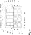
- Fig. 1.1 and 1.2 a first embodiment of the melt spinning apparatus is shown in several views.
- Fig. 1.1 is a schematic longitudinal sectional view and in Fig. 1.2 schematically shown a cross-sectional view. Unless an explicit reference is made to one of the figures, the following description applies to both figures.
- the melt spinning device has a spinning beam 1, which in the Fig. 1.1 and 1.2 only shown with a lower half.
- the spinning beam 1 is designed to be heated.
- the spinning beam 1 has a plurality of depressions 5.1, 5.2 and 5.3, which form a spinneret connection 4.1, 4.2 and 4.3 inside the spinning lime 1 in each case.
- At the spinneret ports 4.1, 4.2 and 4.3 are each a spinneret 2.1. 2.2 and 2.3 held.
- the spinnerets 2.1, 2.2 and 2.3 are usually designed as so-called spinneret packs and can be fastened by screw connections to the spinneret nozzles 4.1, 4.2 and 4.3.
- the recesses 5.1, 5.2 and 5.3 are formed larger in diameter than the spinnerets 2.1, 2.2 and 2.3, so that in each case between the recesses 5.1, 5.2 and 5.3 and the spinnerets 2.1, 2.2 and 2.3 forms an annular gap 6.1, 6.2 and 6.3.
- the spinning beam 1 also comprises a melt distribution system, not shown here, which comprises the spinnerets 2.1, 2.2 and 2.3 with a multiple spinning pump combines.
- the spinning pump, not shown here is also held on the spinning beam 1.
- a cooling device 12 which has a height-adjustable cooling box 13.
- the cooling box 13 is formed in this embodiment as a Radialanblasung.
- the cooling box 13 has an upper blow chamber 14 and a lower distribution chamber 17.
- Within the upper blow chamber 14 a plurality of cooling cylinders 16.1, 16.2 and 16.3 are arranged, each forming an inlet opening 15.1, 15.2 and 15.3.
- the inlet openings 15.1 to 15.3 and the cooling cylinders 16.1 to 16.3 are held coaxially with the spinnerets 2.1, 2.2 and 2.3 so that a filament bundle respectively generated by the spinnerets 2.1 to 2.3 can enter the cooling box 13 via the inlet openings 15.1 to 15.3.
- the cooling cylinders 16.1 to 16.3 open into a plurality of pipe sockets 18.1, 18.2 and 18.3, which are arranged in the lower distribution chamber 17.
- the pipe sockets 18.1 to 18.3 each form an outlet opening 21.1, 21.2 and 21.3 on the underside of the cooling box 13.
- the distribution chamber 17 is coupled via an air connection 19 with a cooling air source, not shown here.
- an inflowing cooling air can be guided via a perforated plate 20 into the upper blow chamber 14.
- the cooling cylinders 16.1 to 16.3 arranged within the blow chamber 14 have a gas-permeable wall, so that the cooling air entering inside a blow chamber 14 flows radially from outside to inside via the cooling cylinders 16.1 to 16.3 onto the filament strands routed through the cooling box 13.
- the distribution pipe 17 arranged pipe sockets 18.1 to 18.3 each have a closed cylinder wall.
- the sleeve carrier 10 has a plurality of firmly upstanding sleeves 18.1, 18.2 and 18.3, which are associated with a lower end of the sleeve 7.1, 7.2 and 7.3 the inlet openings 15.1, 15.2 and 15.3 and with an upper sleeve end 9.1, 9.2 and 9.3 in the recesses 5.1, 5.2 and 5.3 of the spinner 1 protrude.
- the sleeve end 9.1, 9.2 and 9.3 of the sleeves 8.1, 8.2 and 8.3 is dimensioned such that the sleeve ends 9.1 to 9.3 protrude into the annular gaps 6.1, 6.2 and 6.3.
- the sleeves 8.1 to 8.3 thus form a transition zone between the spinnerets 2.1 to 2.3 and the cooling device 12, in which the filaments receive no active cooling.
- the sleeve carrier 10 is formed by a plate 11 which is fixed to the top of the cooling box 13.
- the sleeve carrier 10 and the cooling box 13 form a structural unit which is height-adjustable relative to the spinning beam 1.
- the height adjustment of the cooling box 13 is not shown here. It can be advantageously carried out via pneumatic or hydraulic control units that can hold the cooling box 13 and thus the sleeve ends 9.1, 9.2 and 9.3 in any position relative to the spinning beam 1.
- the set between the spinnerets 2.1 to 2.3 and the cooling box 13 length of the shielding zone through the sleeves 8.1 to 8.3 can be adjusted continuously.
- the in the Fig. 1.1 and 1.2 shown number of spinnerets on the underside of the spinner 1 is an example.
- the spinnerets can be held in a plurality of single-row or multi-row on the underside of the spinner.
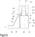
- Fig. 2.1 to 2.2 a further embodiment of the melt spinning device according to the invention is shown.
- the embodiment is in Fig. 2.1 in a longitudinal sectional view and in Fig. 2.2 shown schematically in a cross-sectional view. Unless an explicit reference is made to one of the figures, the following description applies to both figures.
- the spinning beam 1 is identical to the embodiment according to Fig. 1.1 and 1.2 executed, so that at this point to the above description, reference is made and to avoid repetition no further explanation.
- the cooling device 12 is designed as a cross-flow blowing.
- the cooling box 13 on an elongated cooling shaft 26, which forms an inlet opening 15, which extends over the spinnerets 2.1 to 2.3.
- the cooling shaft extends downwardly along a blow chamber 28, which is connected via a blowing wall 27 with the cooling shaft 26.
- the cooling shaft is open at the bottom and forms an outlet opening 21.
- the laterally adjacent to the cooling shaft 26 upstream blow chamber 28 is coupled via a Lauftan gleich 19 with a cooling air source, not shown here.
- a sleeve carrier 10 is arranged in the form of a heating box 22.
- the heating box 22 is penetrated by the sleeve ends 7.1 to 7.3 of the sleeves 8.1 to 8.3, which are associated with the inlet opening 15 at the top of the cooling box 13.
- the function for shielding and for forming a transition zone is identical to the embodiment according to FIG Fig. 1.1 and 1.2 , In the embodiment according to Fig. 2.1 and 2.2 the sleeves 8.1 to 8.3 are heated by the heating box 22.
- the heating box 22 is connected via an inlet 23 and a drain 24 to a heat transfer fluid circuit, not shown here, so that within the heating box 22, the sleeve ends 9.1 to 9.3 of the sleeves 8.1 to 8.3 are lapped with a heat transfer fluid, so that heating of the sleeves 8.1 to 8.3 takes place.
- an insulation 25 is disposed between the heating box 22 and the cooling box 13.
- This in Fig. 2.1 and 2.2 illustrated embodiment of the melt spinning device thus also allows a continuous adjustment of the length of the transition zone between the spinnerets 2.1 to 2.3 and the cooling box 13.
- a length of the transition zone between the spinning beam 1 and the cooling device 12 a This makes it possible to form variable transition zones for the slowed cooling of the filament strands after extrusion.
- the sleeve carrier 10 can be achieved with the sleeves 8.1 to 8.3 of the cooling device 12, so that the cooling device 12 can be held with the cooling box 10 and the insulation 25 directly to the bottom 3 of the spinner 1.
- the thread production can be realized without an additional shielding.
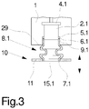
- FIG. 3 another embodiment of a melt spinning apparatus is shown schematically in a cross-sectional view.
- the spinning beam 1 with the sleeve carrier 10 and one of the sleeves 8.1 is shown.
- the cooling device 12 located below the sleeve carrier 10 has not been shown since the variant according to FIG Fig. 3 optionally with the embodiment according to Fig. 1.1 or 2.1 can be combined.
- the sleeve 8.1 is formed by a bellows 29.
- the bellows 29 extends between the sleeve ends 7.1 and 9.1.
- the sleeve end 9.1 is secured in an annular gap 6.
- the opposite sleeve end 7.1 is also attached to the sleeve carrier 10.
- the sleeve carrier can be adjusted in height, so that the bellows 29 is stretched or compressed depending on the direction of adjustment.
- the change in length can thus be realized solely by the bellows 29.
- the bellows 29 is preferably made of a wire mesh having thermally conductive properties. Therefore, the in Fig. 3 illustrated embodiment also run heated.
- a further embodiment of a sleeve carrier 10 is shown, for example, in the melt spinning device according to Fig. 1.1 or Fig. 2.1 could be used.
- the embodiment according to Fig. 4 is essentially identical to the embodiment according to Fig. 2.1 ,
- the sleeve carrier 10 is executed in this case by a heating box 22.
- the heating box is penetrated by the sleeve ends 7.1 to 7.3, wherein in Fig. 4 only the sleeve end 7.1 of the sleeve 8.1 is shown.
- a metal powder 33 is arranged, which is heated by two electrically heated heating elements 31.
- the heating elements 31 extend substantially over the entire length of the spinneret 1.
- the sleeves connected to the heating box 22 8.1 to 8.3 can be heated.
- the heating elements 31 could also be replaced by a heat pipe system.
- the metal powder 30 is heated within the heating box 22 by a respective heat pipe.
- the sleeve carrier 10 is formed as a plate 11, as in the embodiment according to Fig. 1.1 and 1.2 shown, a heating of the sleeves 8.1 to 8.3 could be done directly by an electric heating tape.
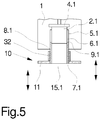
- the sleeve carrier 10 is designed as a plate 11 and carries the towering sleeves 8.1 to 8.3, wherein in Fig. 5 only the sleeve 8.1 is shown.
- the held on the sleeve carrier 10 sleeve end 7.1 is associated with a strip heater 32 in the immediate vicinity, which is held on the circumference of the sleeve 8.1.
- Sleeves 8.2 and 8.3 also have an electrical heating tape 32, so that each of the transition zones is executable with a heated sleeve.
- the embodiments shown in the figures represent only a few design options to allow by means of a height-adjustable sleeve carrier 10, a simultaneous parallel adjustment of a plurality of spinnerets associated sleeves.
- the key here is that cooperation between the cooling device 12 and the sleeve carrier 10, for setting a desired length of the transition zone for shielding possible cooling air flows immediately below the spinnerets.
Landscapes
- Engineering & Computer Science (AREA)
- Mechanical Engineering (AREA)
- Textile Engineering (AREA)
- Spinning Methods And Devices For Manufacturing Artificial Fibers (AREA)
Claims (13)
- Dispositif de filage par fusion avec plusieurs filières (2.1, 2.2) maintenues sur une tête de filage (1) pouvant être chauffée, et avec un dispositif de refroidissement (12) qui présente une boîte de refroidissement (13) réglable en hauteur au niveau d'un dessous (3) de la tête de filage (1), dans lequel la boîte de refroidissement (13) présente une ou plusieurs ouvertures d'entrée (15, 15.1, 15.2) associées aux filières (2.1, 2.2),
caractérisé en ce que, entre la boîte de refroidissement (13) et la tête de filage (1), un support de tubes (10) est disposé lequel, par filière (2.1, 2.2), présente un parmi plusieurs tubes (8.1, 8.2) dressés, lesquels sont associés avec une extrémité de tube (7.1, 7.2) à l'ouverture d'entrée, ou aux ouvertures d'entrée (15, 15.1, 15.2) de la boîte de refroidissement (13) et lesquels pénètrent avec une extrémité de tube libre (9.1, 9.2) située en vis-à-vis respectivement dans une fente annulaire (6.1, 6.2) entre l'une des filières (2.1, 2.2) et la tête de filage (1). - Dispositif de filage par fusion selon la revendication 1, caractérisé en ce que la tête de filage (10) avec des tubes (8.1, 8.2) dressés de manière fixe est maintenue au niveau d'un dessus de la boîte de refroidissement (13) et que la boîte de refroidissement (13) est réglable en continu pour le réglage d'une profondeur d'enfoncement de l'extrémité libre de tube (9.1, 9.2) dans la tête de filage (1).
- Dispositif de filage par fusion selon la revendication 1, caractérisé en ce que les tubes (8.1, 8.2) sont formés respectivement par un soufflet (29) entre les extrémités de tube (7.1, 7.2, 9.1, 9.2), dans lequel la boîte de refroidissement (13) est réglable en continu pour le réglage d'une longueur de soufflet des soufflets (29).
- Dispositif de filage par fusion selon l'une des revendications 1 à 3, caractérisé en ce que le support de tubes (10) est relié de manière détachable à la boîte de refroidissement (13) et que la boîte de refroidissement (13) peut être mise en place, avec ou sans support de tubes (10) au choix, au niveau du dessous (3) de la tête de filage (1).
- Dispositif de filage par fusion selon l'une des revendications 1 à 4, caractérisé en ce que le support de tubes (10) est formé par une plaque supérieure (11) de la boîte de refroidissement (13).
- Dispositif de filage par fusion selon l'une des revendications 1 à 4, caractérisé en ce que le support de tubes (10) est formé par une boîte de chauffage (22) et les tubes (8.1, 8.2) par un matériau thermoconducteur, dans lequel les extrémités de tube (7.1, 7.2) des tubes (8.1, 8.2) peuvent être chauffées par un milieu de chauffage conservé à l'intérieur de la boîte de chauffage (22).
- Dispositif de filage par fusion selon la revendication 6, caractérisé en ce que le milieu de chauffage est une poudre métallique (30) pouvant être chauffée par des thermoplongeurs électriques (31) ou par un système à caloducs.
- Dispositif de filage par fusion selon la revendication 6, caractérisé en ce que le milieu de chauffage est formé par un fluide caloporteur, dans lequel la boîte de chauffage (22) est raccordée à un circuit caloporteur.
- Dispositif de filage par fusion selon l'une des revendications 1 à 5, caractérisé en ce que les tubes (8.1, 8.2) peuvent être chauffés sur le pourtour respectivement par un ruban chauffant électrique (32).
- Dispositif de filage par fusion selon l'une des revendications 6 à 9, caractérisé en ce qu'une isolation thermique (25) est disposée entre le support de tubes (10) et la boîte de refroidissement (13).
- Dispositif de filage par fusion selon l'une des revendications 1 à 10, caractérisé en ce que la boîte de refroidissement (13) présente plusieurs cylindres de refroidissement perméables à l'air (16.1, 16.2), lesquels sont disposés dans une chambre de soufflage supérieure (14) et forment les ouvertures d'entrée (15.1, 15.2), et que plusieurs tubulures (18.1, 18.2) sont associées aux cylindres de refroidissement (16.1, 16.2) sur un côté de sortie, lesquelles sont disposées à l'intérieur d'une chambre de répartition (17) et forment plusieurs ouvertures de sortie (21.1, 21.2) au niveau d'un dessous de la boîte de refroidissement (13).
- Dispositif de filage par fusion selon la revendication 11, caractérisé en ce qu'une tôle perforée (20) est disposée entre la chambre de soufflage (14) et la chambre de répartition (17) et que la chambre de répartition (17) est reliée à une source d'air de refroidissement.
- Dispositif de filage par fusion selon l'une des revendications 1 à 10, caractérisé en ce que la boîte de refroidissement (13) présente un puits de refroidissement (26) allongé formant l'ouverture d'entrée (15), lequel s'étend vers le bas le long d'une chambre de soufflage (28) disposée latéralement et est relié par une paroi de soufflage (27) à la chambre de soufflage (28).
Applications Claiming Priority (2)
| Application Number | Priority Date | Filing Date | Title |
|---|---|---|---|
| DE102014014728.2A DE102014014728A1 (de) | 2014-10-04 | 2014-10-04 | Schmelzspinnvorrichtung |
| PCT/EP2015/072655 WO2016050897A1 (fr) | 2014-10-04 | 2015-10-01 | Dispositif de filage à l'état fondu |
Publications (2)
| Publication Number | Publication Date |
|---|---|
| EP3201376A1 EP3201376A1 (fr) | 2017-08-09 |
| EP3201376B1 true EP3201376B1 (fr) | 2018-09-19 |
Family
ID=54207514
Family Applications (1)
| Application Number | Title | Priority Date | Filing Date |
|---|---|---|---|
| EP15771599.6A Not-in-force EP3201376B1 (fr) | 2014-10-04 | 2015-10-01 | Appareil de filage a chaud |
Country Status (6)
| Country | Link |
|---|---|
| EP (1) | EP3201376B1 (fr) |
| JP (1) | JP2017534774A (fr) |
| KR (1) | KR20170066392A (fr) |
| CN (1) | CN107075734B (fr) |
| DE (1) | DE102014014728A1 (fr) |
| WO (1) | WO2016050897A1 (fr) |
Families Citing this family (4)
| Publication number | Priority date | Publication date | Assignee | Title |
|---|---|---|---|---|
| KR102400547B1 (ko) * | 2017-01-26 | 2022-05-19 | 코오롱인더스트리 주식회사 | 고강도 폴리에스테르 원사의 제조 장치 및 그 제조 방법 |
| CN113737291B (zh) * | 2020-05-29 | 2023-12-19 | 欧瑞康纺织有限及两合公司 | 熔纺设备 |
| CN113089114B (zh) * | 2021-03-24 | 2022-07-19 | 湖州市中跃化纤有限公司 | 一种提高粗旦多孔异形长丝pet-poy内在质量均匀性的工艺方法 |
| CN114808160B (zh) * | 2022-05-31 | 2023-08-11 | 浙江安吉华逸化纤有限公司 | 一种单层石墨烯多功能复合纤维熔体纺丝设备及工艺 |
Family Cites Families (6)
| Publication number | Priority date | Publication date | Assignee | Title |
|---|---|---|---|---|
| US4902461A (en) * | 1987-03-20 | 1990-02-20 | Barmag, Ag | Method for heating an advancing yarn |
| ITPR20010091A1 (it) | 2001-12-21 | 2003-06-21 | Moroder Sa | Camino chiuso radiale di filatura multibava e procedimento di conduzione dell'impianto di filatura. |
| DE102010020187A1 (de) * | 2010-05-11 | 2011-11-17 | Oerlikon Textile Gmbh & Co. Kg | Verfahren und Vorrichtung zum Schmelzspinnen und Abkühlen einer Vielzahl synthetischer Fäden |
| DE102011117458A1 (de) * | 2011-11-02 | 2013-05-02 | Oerlikon Textile Gmbh & Co. Kg | Vorrichtung zum Schmelzspinnen und Abkühlen von synthetischen Filamenten |
| CN103374762B (zh) * | 2012-04-26 | 2016-12-21 | 欧瑞康纺织技术(北京)有限公司 | 用于熔融纺丝和冷却合成长丝的设备 |
| CN203498516U (zh) * | 2013-10-22 | 2014-03-26 | 欧瑞康纺织有限及两合公司 | 用于熔融纺丝和冷却合成长丝的设备 |
-
2014
- 2014-10-04 DE DE102014014728.2A patent/DE102014014728A1/de not_active Withdrawn
-
2015
- 2015-10-01 EP EP15771599.6A patent/EP3201376B1/fr not_active Not-in-force
- 2015-10-01 WO PCT/EP2015/072655 patent/WO2016050897A1/fr active Application Filing
- 2015-10-01 CN CN201580053393.5A patent/CN107075734B/zh active Active
- 2015-10-01 JP JP2017518239A patent/JP2017534774A/ja active Pending
- 2015-10-01 KR KR1020177009034A patent/KR20170066392A/ko unknown
Non-Patent Citations (1)
| Title |
|---|
| None * |
Also Published As
| Publication number | Publication date |
|---|---|
| DE102014014728A1 (de) | 2016-04-07 |
| CN107075734B (zh) | 2019-05-10 |
| KR20170066392A (ko) | 2017-06-14 |
| WO2016050897A1 (fr) | 2016-04-07 |
| EP3201376A1 (fr) | 2017-08-09 |
| CN107075734A (zh) | 2017-08-18 |
| JP2017534774A (ja) | 2017-11-24 |
Similar Documents
| Publication | Publication Date | Title |
|---|---|---|
| EP3201376B1 (fr) | Appareil de filage a chaud | |
| EP1902164B1 (fr) | Dispositif de filature et procede pour produire des fils fins par epissurage afin d'obtenir un nontisse, et nontisse susceptible d'etre obtenu ainsi | |
| WO1992002316A1 (fr) | Dispositif de refroidissement de profiles extrudes | |
| EP2773798A1 (fr) | Dispositif de filage à chaud et de refroidissement de filaments synthétiques | |
| DE102013012869A1 (de) | Vorrichtung zum Schmelzspinnen und Abkühlen von Filamentsträngen | |
| WO2016173828A1 (fr) | Procédé et dispositif de filage à chaud et de refroidissement de fils multibrins | |
| DE202008015313U1 (de) | Vorrichtung zum Abkühlen mehrerer synthetischer Filamentbündel | |
| DE102016112394A1 (de) | Vorrichtung zum Schmelzspinnen und Abkühlen einer Filamentschar | |
| EP0781877B1 (fr) | Dispositif pour le filage au fondu | |
| DE102015012846A1 (de) | Schmelzspinnvorrichtung | |
| DE202008015315U1 (de) | Vorrichtung zum Schmelzspinnen und Abkühlen mehrerer synthetischer Fäden | |
| DE102014007454A1 (de) | Vorrichtung zum Abziehen und Verstecken einer synthetischen Fadenschar | |
| EP2122019B1 (fr) | Dispositif de filage à chaud de filaments synthétiques | |
| WO2002090632A1 (fr) | Dispositif de frisage par compression d'un fil mulfilament synthetique | |
| EP2049714B1 (fr) | Machine à texturer | |
| DE2218239C3 (de) | Vorrichtung zum Schmelzspinnen von Filamenten aus einem synthetischen Polymerisat | |
| DE60308469T2 (de) | Spritzgiessdüse mit einer abnehmbaren und ersetzbaren Heizvorrichtung | |
| EP2627808B1 (fr) | Dispositif pour le traitement thermique de plusiers fils | |
| WO2012097880A1 (fr) | Dispositif de refroidissement d'une pluralité de fils synthétiques | |
| DE102013014572A1 (de) | Vorrichtung zum Schmelzspinnen und Abkühlen synthetischer Filamente | |
| DE102005048334A1 (de) | Vorrichtung zum Schmelzspinnen und Kühlen einer synthetischen Filamentschar | |
| DE10053731A1 (de) | Vorrichtung zum Schmelzspinnen | |
| DE102007019353B4 (de) | Schmelzblaseinrichtung und Verfahren zum Zuführen von Prozessluft in einer Schmelzblaseinrichtung | |
| DE10348865A1 (de) | Spinndüse mit innerer Heizung für Spinnvliese und Garne | |
| DE19735571C2 (de) | Spinneinrichtung zum Ausspinnen von Filamenten aus synthetischen Polymeren |
Legal Events
| Date | Code | Title | Description |
|---|---|---|---|
| PUAI | Public reference made under article 153(3) epc to a published international application that has entered the european phase |
Free format text: ORIGINAL CODE: 0009012 |
|
| 17P | Request for examination filed |
Effective date: 20170425 |
|
| AK | Designated contracting states |
Kind code of ref document: A1 Designated state(s): AL AT BE BG CH CY CZ DE DK EE ES FI FR GB GR HR HU IE IS IT LI LT LU LV MC MK MT NL NO PL PT RO RS SE SI SK SM TR |
|
| AX | Request for extension of the european patent |
Extension state: BA ME |
|
| DAV | Request for validation of the european patent (deleted) | ||
| DAX | Request for extension of the european patent (deleted) | ||
| GRAP | Despatch of communication of intention to grant a patent |
Free format text: ORIGINAL CODE: EPIDOSNIGR1 |
|
| INTG | Intention to grant announced |
Effective date: 20180522 |
|
| GRAS | Grant fee paid |
Free format text: ORIGINAL CODE: EPIDOSNIGR3 |
|
| GRAA | (expected) grant |
Free format text: ORIGINAL CODE: 0009210 |
|
| AK | Designated contracting states |
Kind code of ref document: B1 Designated state(s): AL AT BE BG CH CY CZ DE DK EE ES FI FR GB GR HR HU IE IS IT LI LT LU LV MC MK MT NL NO PL PT RO RS SE SI SK SM TR |
|
| REG | Reference to a national code |
Ref country code: GB Ref legal event code: FG4D Free format text: NOT ENGLISH |
|
| REG | Reference to a national code |
Ref country code: CH Ref legal event code: EP |
|
| REG | Reference to a national code |
Ref country code: AT Ref legal event code: REF Ref document number: 1043381 Country of ref document: AT Kind code of ref document: T Effective date: 20181015 |
|
| REG | Reference to a national code |
Ref country code: IE Ref legal event code: FG4D Free format text: LANGUAGE OF EP DOCUMENT: GERMAN |
|
| REG | Reference to a national code |
Ref country code: DE Ref legal event code: R096 Ref document number: 502015006009 Country of ref document: DE |
|
| REG | Reference to a national code |
Ref country code: NL Ref legal event code: MP Effective date: 20180919 |
|
| PG25 | Lapsed in a contracting state [announced via postgrant information from national office to epo] |
Ref country code: NO Free format text: LAPSE BECAUSE OF FAILURE TO SUBMIT A TRANSLATION OF THE DESCRIPTION OR TO PAY THE FEE WITHIN THE PRESCRIBED TIME-LIMIT Effective date: 20181219 Ref country code: LT Free format text: LAPSE BECAUSE OF FAILURE TO SUBMIT A TRANSLATION OF THE DESCRIPTION OR TO PAY THE FEE WITHIN THE PRESCRIBED TIME-LIMIT Effective date: 20180919 Ref country code: RS Free format text: LAPSE BECAUSE OF FAILURE TO SUBMIT A TRANSLATION OF THE DESCRIPTION OR TO PAY THE FEE WITHIN THE PRESCRIBED TIME-LIMIT Effective date: 20180919 Ref country code: FI Free format text: LAPSE BECAUSE OF FAILURE TO SUBMIT A TRANSLATION OF THE DESCRIPTION OR TO PAY THE FEE WITHIN THE PRESCRIBED TIME-LIMIT Effective date: 20180919 Ref country code: SE Free format text: LAPSE BECAUSE OF FAILURE TO SUBMIT A TRANSLATION OF THE DESCRIPTION OR TO PAY THE FEE WITHIN THE PRESCRIBED TIME-LIMIT Effective date: 20180919 Ref country code: GR Free format text: LAPSE BECAUSE OF FAILURE TO SUBMIT A TRANSLATION OF THE DESCRIPTION OR TO PAY THE FEE WITHIN THE PRESCRIBED TIME-LIMIT Effective date: 20181220 Ref country code: BG Free format text: LAPSE BECAUSE OF FAILURE TO SUBMIT A TRANSLATION OF THE DESCRIPTION OR TO PAY THE FEE WITHIN THE PRESCRIBED TIME-LIMIT Effective date: 20181219 |
|
| REG | Reference to a national code |
Ref country code: LT Ref legal event code: MG4D |
|
| PG25 | Lapsed in a contracting state [announced via postgrant information from national office to epo] |
Ref country code: LV Free format text: LAPSE BECAUSE OF FAILURE TO SUBMIT A TRANSLATION OF THE DESCRIPTION OR TO PAY THE FEE WITHIN THE PRESCRIBED TIME-LIMIT Effective date: 20180919 Ref country code: AL Free format text: LAPSE BECAUSE OF FAILURE TO SUBMIT A TRANSLATION OF THE DESCRIPTION OR TO PAY THE FEE WITHIN THE PRESCRIBED TIME-LIMIT Effective date: 20180919 Ref country code: HR Free format text: LAPSE BECAUSE OF FAILURE TO SUBMIT A TRANSLATION OF THE DESCRIPTION OR TO PAY THE FEE WITHIN THE PRESCRIBED TIME-LIMIT Effective date: 20180919 |
|
| PG25 | Lapsed in a contracting state [announced via postgrant information from national office to epo] |
Ref country code: EE Free format text: LAPSE BECAUSE OF FAILURE TO SUBMIT A TRANSLATION OF THE DESCRIPTION OR TO PAY THE FEE WITHIN THE PRESCRIBED TIME-LIMIT Effective date: 20180919 Ref country code: IT Free format text: LAPSE BECAUSE OF FAILURE TO SUBMIT A TRANSLATION OF THE DESCRIPTION OR TO PAY THE FEE WITHIN THE PRESCRIBED TIME-LIMIT Effective date: 20180919 Ref country code: PL Free format text: LAPSE BECAUSE OF FAILURE TO SUBMIT A TRANSLATION OF THE DESCRIPTION OR TO PAY THE FEE WITHIN THE PRESCRIBED TIME-LIMIT Effective date: 20180919 Ref country code: RO Free format text: LAPSE BECAUSE OF FAILURE TO SUBMIT A TRANSLATION OF THE DESCRIPTION OR TO PAY THE FEE WITHIN THE PRESCRIBED TIME-LIMIT Effective date: 20180919 Ref country code: CZ Free format text: LAPSE BECAUSE OF FAILURE TO SUBMIT A TRANSLATION OF THE DESCRIPTION OR TO PAY THE FEE WITHIN THE PRESCRIBED TIME-LIMIT Effective date: 20180919 Ref country code: NL Free format text: LAPSE BECAUSE OF FAILURE TO SUBMIT A TRANSLATION OF THE DESCRIPTION OR TO PAY THE FEE WITHIN THE PRESCRIBED TIME-LIMIT Effective date: 20180919 Ref country code: ES Free format text: LAPSE BECAUSE OF FAILURE TO SUBMIT A TRANSLATION OF THE DESCRIPTION OR TO PAY THE FEE WITHIN THE PRESCRIBED TIME-LIMIT Effective date: 20180919 Ref country code: IS Free format text: LAPSE BECAUSE OF FAILURE TO SUBMIT A TRANSLATION OF THE DESCRIPTION OR TO PAY THE FEE WITHIN THE PRESCRIBED TIME-LIMIT Effective date: 20190119 |
|
| PG25 | Lapsed in a contracting state [announced via postgrant information from national office to epo] |
Ref country code: SK Free format text: LAPSE BECAUSE OF FAILURE TO SUBMIT A TRANSLATION OF THE DESCRIPTION OR TO PAY THE FEE WITHIN THE PRESCRIBED TIME-LIMIT Effective date: 20180919 Ref country code: PT Free format text: LAPSE BECAUSE OF FAILURE TO SUBMIT A TRANSLATION OF THE DESCRIPTION OR TO PAY THE FEE WITHIN THE PRESCRIBED TIME-LIMIT Effective date: 20190119 Ref country code: SM Free format text: LAPSE BECAUSE OF FAILURE TO SUBMIT A TRANSLATION OF THE DESCRIPTION OR TO PAY THE FEE WITHIN THE PRESCRIBED TIME-LIMIT Effective date: 20180919 |
|
| REG | Reference to a national code |
Ref country code: CH Ref legal event code: PL |
|
| REG | Reference to a national code |
Ref country code: DE Ref legal event code: R097 Ref document number: 502015006009 Country of ref document: DE |
|
| REG | Reference to a national code |
Ref country code: BE Ref legal event code: MM Effective date: 20181031 |
|
| PG25 | Lapsed in a contracting state [announced via postgrant information from national office to epo] |
Ref country code: LU Free format text: LAPSE BECAUSE OF NON-PAYMENT OF DUE FEES Effective date: 20181001 |
|
| REG | Reference to a national code |
Ref country code: IE Ref legal event code: MM4A |
|
| PLBE | No opposition filed within time limit |
Free format text: ORIGINAL CODE: 0009261 |
|
| STAA | Information on the status of an ep patent application or granted ep patent |
Free format text: STATUS: NO OPPOSITION FILED WITHIN TIME LIMIT |
|
| PG25 | Lapsed in a contracting state [announced via postgrant information from national office to epo] |
Ref country code: MC Free format text: LAPSE BECAUSE OF FAILURE TO SUBMIT A TRANSLATION OF THE DESCRIPTION OR TO PAY THE FEE WITHIN THE PRESCRIBED TIME-LIMIT Effective date: 20180919 Ref country code: DK Free format text: LAPSE BECAUSE OF FAILURE TO SUBMIT A TRANSLATION OF THE DESCRIPTION OR TO PAY THE FEE WITHIN THE PRESCRIBED TIME-LIMIT Effective date: 20180919 |
|
| 26N | No opposition filed |
Effective date: 20190620 |
|
| PG25 | Lapsed in a contracting state [announced via postgrant information from national office to epo] |
Ref country code: BE Free format text: LAPSE BECAUSE OF NON-PAYMENT OF DUE FEES Effective date: 20181031 Ref country code: CH Free format text: LAPSE BECAUSE OF NON-PAYMENT OF DUE FEES Effective date: 20181031 Ref country code: LI Free format text: LAPSE BECAUSE OF NON-PAYMENT OF DUE FEES Effective date: 20181031 |
|
| PG25 | Lapsed in a contracting state [announced via postgrant information from national office to epo] |
Ref country code: IE Free format text: LAPSE BECAUSE OF NON-PAYMENT OF DUE FEES Effective date: 20181001 Ref country code: SI Free format text: LAPSE BECAUSE OF FAILURE TO SUBMIT A TRANSLATION OF THE DESCRIPTION OR TO PAY THE FEE WITHIN THE PRESCRIBED TIME-LIMIT Effective date: 20180919 Ref country code: FR Free format text: LAPSE BECAUSE OF NON-PAYMENT OF DUE FEES Effective date: 20181119 |
|
| PG25 | Lapsed in a contracting state [announced via postgrant information from national office to epo] |
Ref country code: MT Free format text: LAPSE BECAUSE OF FAILURE TO SUBMIT A TRANSLATION OF THE DESCRIPTION OR TO PAY THE FEE WITHIN THE PRESCRIBED TIME-LIMIT Effective date: 20180919 |
|
| PGFP | Annual fee paid to national office [announced via postgrant information from national office to epo] |
Ref country code: DE Payment date: 20191021 Year of fee payment: 5 |
|
| PG25 | Lapsed in a contracting state [announced via postgrant information from national office to epo] |
Ref country code: TR Free format text: LAPSE BECAUSE OF FAILURE TO SUBMIT A TRANSLATION OF THE DESCRIPTION OR TO PAY THE FEE WITHIN THE PRESCRIBED TIME-LIMIT Effective date: 20180919 |
|
| PG25 | Lapsed in a contracting state [announced via postgrant information from national office to epo] |
Ref country code: MK Free format text: LAPSE BECAUSE OF NON-PAYMENT OF DUE FEES Effective date: 20180919 Ref country code: CY Free format text: LAPSE BECAUSE OF FAILURE TO SUBMIT A TRANSLATION OF THE DESCRIPTION OR TO PAY THE FEE WITHIN THE PRESCRIBED TIME-LIMIT Effective date: 20180919 Ref country code: HU Free format text: LAPSE BECAUSE OF FAILURE TO SUBMIT A TRANSLATION OF THE DESCRIPTION OR TO PAY THE FEE WITHIN THE PRESCRIBED TIME-LIMIT; INVALID AB INITIO Effective date: 20151001 |
|
| GBPC | Gb: european patent ceased through non-payment of renewal fee |
Effective date: 20191001 |
|
| PG25 | Lapsed in a contracting state [announced via postgrant information from national office to epo] |
Ref country code: GB Free format text: LAPSE BECAUSE OF NON-PAYMENT OF DUE FEES Effective date: 20191001 |
|
| REG | Reference to a national code |
Ref country code: DE Ref legal event code: R119 Ref document number: 502015006009 Country of ref document: DE |
|
| PG25 | Lapsed in a contracting state [announced via postgrant information from national office to epo] |
Ref country code: DE Free format text: LAPSE BECAUSE OF NON-PAYMENT OF DUE FEES Effective date: 20210501 |
|
| REG | Reference to a national code |
Ref country code: AT Ref legal event code: MM01 Ref document number: 1043381 Country of ref document: AT Kind code of ref document: T Effective date: 20201001 |
|
| PG25 | Lapsed in a contracting state [announced via postgrant information from national office to epo] |
Ref country code: AT Free format text: LAPSE BECAUSE OF NON-PAYMENT OF DUE FEES Effective date: 20201001 |