EP3200675B1 - Mit sensoren mit variabler impedanz ausgestattete, medizinische vorrichtung - Google Patents
Mit sensoren mit variabler impedanz ausgestattete, medizinische vorrichtung Download PDFInfo
- Publication number
- EP3200675B1 EP3200675B1 EP15771665.5A EP15771665A EP3200675B1 EP 3200675 B1 EP3200675 B1 EP 3200675B1 EP 15771665 A EP15771665 A EP 15771665A EP 3200675 B1 EP3200675 B1 EP 3200675B1
- Authority
- EP
- European Patent Office
- Prior art keywords
- medical device
- sensor
- sensors
- switch
- implantable
- Prior art date
- Legal status (The legal status is an assumption and is not a legal conclusion. Google has not performed a legal analysis and makes no representation as to the accuracy of the status listed.)
- Active
Links
Images


Classifications
-
- A—HUMAN NECESSITIES
- A61—MEDICAL OR VETERINARY SCIENCE; HYGIENE
- A61B—DIAGNOSIS; SURGERY; IDENTIFICATION
- A61B5/00—Measuring for diagnostic purposes; Identification of persons
- A61B5/68—Arrangements of detecting, measuring or recording means, e.g. sensors, in relation to patient
- A61B5/6846—Arrangements of detecting, measuring or recording means, e.g. sensors, in relation to patient specially adapted to be brought in contact with an internal body part, i.e. invasive
- A61B5/6847—Arrangements of detecting, measuring or recording means, e.g. sensors, in relation to patient specially adapted to be brought in contact with an internal body part, i.e. invasive mounted on an invasive device
- A61B5/6862—Stents
-
- A—HUMAN NECESSITIES
- A61—MEDICAL OR VETERINARY SCIENCE; HYGIENE
- A61B—DIAGNOSIS; SURGERY; IDENTIFICATION
- A61B5/00—Measuring for diagnostic purposes; Identification of persons
- A61B5/0002—Remote monitoring of patients using telemetry, e.g. transmission of vital signals via a communication network
- A61B5/0031—Implanted circuitry
-
- A—HUMAN NECESSITIES
- A61—MEDICAL OR VETERINARY SCIENCE; HYGIENE
- A61B—DIAGNOSIS; SURGERY; IDENTIFICATION
- A61B5/00—Measuring for diagnostic purposes; Identification of persons
- A61B5/05—Detecting, measuring or recording for diagnosis by means of electric currents or magnetic fields; Measuring using microwaves or radio waves
- A61B5/053—Measuring electrical impedance or conductance of a portion of the body
- A61B5/0538—Measuring electrical impedance or conductance of a portion of the body invasively, e.g. using a catheter
-
- A—HUMAN NECESSITIES
- A61—MEDICAL OR VETERINARY SCIENCE; HYGIENE
- A61B—DIAGNOSIS; SURGERY; IDENTIFICATION
- A61B5/00—Measuring for diagnostic purposes; Identification of persons
- A61B5/48—Other medical applications
- A61B5/4851—Prosthesis assessment or monitoring
-
- A—HUMAN NECESSITIES
- A61—MEDICAL OR VETERINARY SCIENCE; HYGIENE
- A61B—DIAGNOSIS; SURGERY; IDENTIFICATION
- A61B5/00—Measuring for diagnostic purposes; Identification of persons
- A61B5/68—Arrangements of detecting, measuring or recording means, e.g. sensors, in relation to patient
- A61B5/6846—Arrangements of detecting, measuring or recording means, e.g. sensors, in relation to patient specially adapted to be brought in contact with an internal body part, i.e. invasive
- A61B5/6847—Arrangements of detecting, measuring or recording means, e.g. sensors, in relation to patient specially adapted to be brought in contact with an internal body part, i.e. invasive mounted on an invasive device
- A61B5/686—Permanently implanted devices, e.g. pacemakers, other stimulators, biochips
-
- A—HUMAN NECESSITIES
- A61—MEDICAL OR VETERINARY SCIENCE; HYGIENE
- A61B—DIAGNOSIS; SURGERY; IDENTIFICATION
- A61B5/00—Measuring for diagnostic purposes; Identification of persons
- A61B5/72—Signal processing specially adapted for physiological signals or for diagnostic purposes
- A61B5/7225—Details of analogue processing, e.g. isolation amplifier, gain or sensitivity adjustment, filtering, baseline or drift compensation
-
- A—HUMAN NECESSITIES
- A61—MEDICAL OR VETERINARY SCIENCE; HYGIENE
- A61B—DIAGNOSIS; SURGERY; IDENTIFICATION
- A61B2560/00—Constructional details of operational features of apparatus; Accessories for medical measuring apparatus
- A61B2560/02—Operational features
- A61B2560/0204—Operational features of power management
- A61B2560/0214—Operational features of power management of power generation or supply
- A61B2560/0219—Operational features of power management of power generation or supply of externally powered implanted units
-
- A—HUMAN NECESSITIES
- A61—MEDICAL OR VETERINARY SCIENCE; HYGIENE
- A61B—DIAGNOSIS; SURGERY; IDENTIFICATION
- A61B2562/00—Details of sensors; Constructional details of sensor housings or probes; Accessories for sensors
- A61B2562/02—Details of sensors specially adapted for in-vivo measurements
- A61B2562/0247—Pressure sensors
-
- A—HUMAN NECESSITIES
- A61—MEDICAL OR VETERINARY SCIENCE; HYGIENE
- A61B—DIAGNOSIS; SURGERY; IDENTIFICATION
- A61B2562/00—Details of sensors; Constructional details of sensor housings or probes; Accessories for sensors
- A61B2562/02—Details of sensors specially adapted for in-vivo measurements
- A61B2562/0261—Strain gauges
-
- A—HUMAN NECESSITIES
- A61—MEDICAL OR VETERINARY SCIENCE; HYGIENE
- A61B—DIAGNOSIS; SURGERY; IDENTIFICATION
- A61B2562/00—Details of sensors; Constructional details of sensor housings or probes; Accessories for sensors
- A61B2562/02—Details of sensors specially adapted for in-vivo measurements
- A61B2562/0271—Thermal or temperature sensors
-
- A—HUMAN NECESSITIES
- A61—MEDICAL OR VETERINARY SCIENCE; HYGIENE
- A61B—DIAGNOSIS; SURGERY; IDENTIFICATION
- A61B2562/00—Details of sensors; Constructional details of sensor housings or probes; Accessories for sensors
- A61B2562/02—Details of sensors specially adapted for in-vivo measurements
- A61B2562/028—Microscale sensors, e.g. electromechanical sensors [MEMS]
-
- A—HUMAN NECESSITIES
- A61—MEDICAL OR VETERINARY SCIENCE; HYGIENE
- A61F—FILTERS IMPLANTABLE INTO BLOOD VESSELS; PROSTHESES; DEVICES PROVIDING PATENCY TO, OR PREVENTING COLLAPSING OF, TUBULAR STRUCTURES OF THE BODY, e.g. STENTS; ORTHOPAEDIC, NURSING OR CONTRACEPTIVE DEVICES; FOMENTATION; TREATMENT OR PROTECTION OF EYES OR EARS; BANDAGES, DRESSINGS OR ABSORBENT PADS; FIRST-AID KITS
- A61F2/00—Filters implantable into blood vessels; Prostheses, i.e. artificial substitutes or replacements for parts of the body; Appliances for connecting them with the body; Devices providing patency to, or preventing collapsing of, tubular structures of the body, e.g. stents
- A61F2/82—Devices providing patency to, or preventing collapsing of, tubular structures of the body, e.g. stents
Definitions
- the present invention relates to a medical device implantable in the human body provided with sensors, with variable impedance.
- the invention also relates to a medical system comprising such a medical device and a method for interrogating such a medical device, in particular in a medical system.
- the invention relates in particular to an implantable medical device such as a stent (sometimes also called “arterial endoprosthesis”, “vascular stent” or even simply “spring”) provided with sensors.
- a stent sometimes also called “arterial endoprosthesis”, “vascular stent” or even simply “spring”
- a stent is a tubular-shaped device produced by a deformable mesh, in particular of metal or of a biodegradable polymer material.
- the stent is introduced into a patient's body in a collapsed, mesh-closed condition, and then is extended inside the patient's body, for example by angioplasty which causes mesh to unfold.
- the stent deployed, keeps a cavity open in the patient's body. It is known that the placement of a stent can in particular cause tissue inflammation, hyperplasia and / or blood coagulation.
- a stent can be provided with sensors, which allow monitoring of the condition of the tissues around the stent to possibly tailor the patient's treatment accordingly. Sensors may also be provided to ensure that the stent is fulfilling its function of maintaining an open cavity.
- the patent EP-B-2 271 933 thus describes a method for characterizing cells in the vicinity of a medical device implanted in a patient, in particular a stent, by impedance measurements at different frequencies.
- Requirement WO-A-2009/1 361 677 describes an implantable medical device such as a stent, having an electrically conductive surface and an impedance sensor for measuring the impedance of the conductive surface of the implantable medical device, at different frequencies, using the conductive surface as electrode.
- the measurements carried out are used to determine the degree of restenosis of the tissues at the level of the implantable device, that is to say the thickness of tissue having grown at the level of the conductive surface of the implantable medical device.
- US-B-8,478,378 a stent provided with sensors distributed over its internal surface, oriented towards the passage through the stent, or “luminal” surface.
- the sensors are configured to send a clean characteristic output signal in response to an excitation.
- the specific characteristic signal can in particular be a wavelength specific to each of the sensors.
- US-B-8,478,378 indicates that thus an output signal including signals from all or most of the sensors suggests that a large number of sensors are not covered with a layer of endothelial cells.
- the demand WO-A-2011/121581 describes an implantable medical device capable of responding to an interrogation electromagnetic field emitted by a remote interrogation device.
- the implantable medical device is provided with a plurality of modulators constituted by RFID chips (standing for “Radio-Frequency IDentification” or radio-identification).
- RFID chips are suitable for the implantable medical device to respond to an interrogating electromagnetic field according to modulation generating a respective unique identification code.
- RFID chips as sensors in the medical device, however, limits the number of sensors with which it can be fitted.
- the proliferation of RFID chips increases the price of the medical device by the same amount.
- These RFID chips can also only be used as impedance sensors.
- the medical device must be at least in part made of a metallic material having good electrical conduction.
- the RFID chips must be implanted in the very structure of the implantable medical device, making the realization of the latter particularly complex.
- implantable medical devices have a structure implantable in the body to assist in performing a vital function in the body.
- One or several sensors are associated with this implantable structure, which makes it possible (tent) to measure a parameter associated with the structure.
- these medical devices include a communication circuit coupled to the sensor (s) to deliver a signal that is a function of the measured parameter and to transmit this signal to a reception device, outside the body, in a non-invasive manner.
- the object of the invention is to remedy the problems mentioned above.
- the object of the invention is to propose a medical device of simple structure and therefore of limited cost, making it possible to distinguish the quantities measured by various sensors with which the medical device is fitted.
- the medical device is implantable in the patient's body and configured to allow determination, without intrusion into the patient's body, if it is correctly implanted.
- the invention proposes a medical device comprising an electrical measurement circuit, in which are connected at least two sensors with variable impedance as a function of a physical quantity sensed, a source of electrical energy for supplying the electrical measurement circuit, an antenna to emit an electromagnetic field as a function of the impedance of the electrical measuring circuit, each of the sensors being associated with a switch for short-circuiting the sensor in said measuring circuit, the medical device further comprising a system for controlling switches for successively control the opening or closing of the switches one after the other, according to determined configurations and in which the control system of the switches comprises a control circuit, supplied by the source of electrical energy, the control system being configured for normally keep the switches closed and to open them successively then for ref close so that at any moment a single switch is open.
- the medical device is provided with any type of variable impedance sensors connected together in a so-called measuring circuit.
- a control system makes it possible to short-circuit the various sensors according to predetermined configurations, so that the electromagnetic field emitted by the medical device corresponds to the configuration of the measuring circuit.
- By carrying out successive measurements, corresponding to linearly independent configurations it is very easily possible to obtain qualitative information on the values measured by each of the sensors of the medical device, arranged at known locations on the medical device.
- short-circuiting a sensor is meant creating a circuit configuration such that the current flowing through the sensor is zero, the other sensors being able to be supplied with current.
- short-circuiting a sensor here means cutting off the current supply to this sensor.
- the invention also relates to a medical system comprising a medical device as described above in all its combinations and a unit for receiving information from the medical device, comprising means for picking up the electromagnetic field emitted by the antenna. of the medical device.
- the medical system may further comprise an interrogation unit of the medical device, preferably combined with the information reception unit, preferably comprising means for emitting an electromagnetic field suitable for creating an induced current in the measuring circuit. of the medical device.
- the medical system can also include a processing unit for the information received by the reception unit, for example a computer.
- the figure 1 schematically represents a first example of a medical system comprising a medical device.
- the figure 2 schematically shows a detail of the electrical circuit of the stent of the figure 1 .
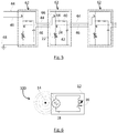
- the figure 3 schematically represents a second example of a medical system comprising a medical device.
- the figure 4 schematically represents a third example of a medical system comprising a medical device.
- the figure 5 schematically shows a detail of the medical device of the figure 4 .
- the figure 6 schematically represents a fourth example of a medical system comprising a medical device.
- the figure 1 schematically illustrates a medical system 10 comprising an implantable medical device 12 and a unit 14, here unique, for interrogating the medical device 12 and receiving information from this same medical device 12.
- a processing unit for the information received by the reception unit, for example a computer.
- the implantable medical device 12 comprises a variable impedance 15.
- the value of this variable impedance 15 is controlled by a control unit, not shown, as a function of the impedance in a measuring circuit 16, notably connecting the various sensors 22 of the medical device.
- implantable also comprises a source of electrical energy, here an electrical current source formed by the body 18 of the implantable medical device 12.
- a source of electrical energy here an electrical current source formed by the body 18 of the implantable medical device 12.
- the body 18 of the implantable medical device 12 induces a current.
- an antenna or an armature separate and electrically isolated from the body 18 of the implantable medical device 12 may also be provided, in particular in the case where the implantable medical device 12 is not suitable, in all or part, to have an armature function.
- a source of electrical energy for the measuring circuit may comprise a current conducting surface of the implantable medical device, suitable for inducing an electric current under the effect of an electromagnetic field.
- a battery or electric cell may also be provided as a source of electric energy for the implantable medical device 12.
- the body 18 of the implantable medical device 12 also serves here as a transmitting antenna, to emit an electromagnetic field towards the outside of the body in which the implantable medical device is implanted.
- the intensity of this field depends directly from the variable impedance 15, a function of the impedance in the measuring circuit 16.
- the intensity or a norm of the electromagnetic field emitted by the body 18 of the implantable medical device 12 is a function of the impedance of the measuring circuit 16.
- the implantable medical device 12 may include an antenna separate from the body of the implantable medical device or the antenna may be formed by at least part of the implantable medical device.
- the implantable medical device 12 is for example a stent.
- the stent is a tubular metal device, preferably meshed, slipped into a natural human (or animal) cavity to keep it open, as described previously in the introduction.
- the stent may for example be made of a metal alloy or of a polymer material, but other materials can also be envisaged.
- the implantable medical device 12 is provided with sensors 22 with variable impedance as a function of the physical quantity that they sense.
- physical quantity we mean here any property of the science of nature which can be quantified by measurement or calculation, and whose different possible values are expressed using any real number or a number complex.
- a physical quantity therefore includes, for example, a length, an electric current, a voltage, an impedance, a concentration of a chemical element or even the presence and / or the concentration of a biological or biochemical element.
- the sensors can be coated with an active agent, for example to limit the hyperplasia of tissues in contact with the implantable medical device, in particular when they are positioned on the abluminal surface of a stent or more generally on the outer surface of a stent.
- an implantable medical device intended to be in contact with the wall of the cavity in which the medical device is implantable.
- a single sensor in particular of a pressure sensor, on the abluminal surface of a stent, or more generally on the external surface of an implantable medical device already makes it possible to have information. relating to the incorrect positioning of the stent or the implantable medical device in the cavity. If the measured pressure is low (i.e. less than a threshold pressure), it is likely that the sensor is not in contact with a wall of the cavity, but rather with blood, for example. In the case where two or more sensors are disposed on the abluminal or outer surface, the information can be obtained more accurately by comparing the values measured by the sensors with each other.
- the sensors are arranged at the locations of the implantable medical device, in particular of a stent, undergoing the least significant deformations when the implantable medical device is put in place, in order to avoid damaging the sensors.
- the sensors 22 are variable impedance sensors, that is to say sensors whose impedance varies as a function of the amplitude or the intensity of the physical quantity captured. Consequently, in the event of a variation in the amplitude of the physical quantity picked up by a sensor of the implantable medical device 12, the impedance of this sensor varies in the measuring circuit 16, so that, in the absence of any other variation in the measuring circuit 16, the impedance of the measuring circuit 16 also varies.
- each sensor 22 is associated with a switch 24 adapted to short-circuit the sensor 22 with which it is associated.
- this is achieved by mounting the switch 24 in bypass (or in parallel) of the sensor 22 with which it is associated.
- the sensors 22 are here mounted in series in the measuring circuit 16.
- each switch is here made by a transistor 24, in this case a silicon MOS-FET transistor, more precisely. an N-channel, enriched (or n-MOS) MOS-FET transistor.
- each switch or certain switches can be produced by another type of transistor, in particular by an FET transistor, a depletion MOS-FET transistor, in particular a depletion P-channel MOS-FET transistor, by a MEMS (from the English "Microelectromechanical system", or by a mechanical switch.
- the figure 1 further illustrates a system 26 for controlling the switches 24, adapted to successively control the opening or closing of the switches 24 according to determined configurations.
- the control system 26 comprises control modules 28 arranged in series with one another, each control module 28 being adapted to control the opening or closing of the switch 24 with which it is associated.
- control system 26 is configured to normally keep the switches 24 closed and to open them successively and then to close them again so that at each instant a single switch 24 is open.
- each control module 28 is formed here of a logic circuit, produced by means of transistors 30, 32, 34, 36, 38, a resistor 40 and a capacitor 42.
- the resistor 40 and the capacitor 42 introduce a charge time of capacitor 42 and a discharge time of this same capacitor 42 into the logic circuit.
- the control module 28 controls the opening of the associated switch 24. Switch 24 is kept closed for the rest of the time, then bypassing the associated sensor 22.
- the voltage at the terminals of the measuring circuit 16 which is equal to the sum of the voltages at the terminals of each of the sensors mounted in series in the measuring circuit, exhibits successive peaks which are representative of the voltage at the terminals of each of the sensors.
- each representative of the voltage at the terminals of a sensor 22 corresponds an intensity of the electromagnetic field emitted by the body 18 of the implantable medical device 12 having a transmitting antenna function.
- a rectifier 56 as well as an alternating current generator 58 in the implantable medical device 12. They respectively make it possible to supply the control circuit 26 with direct current and the measuring circuit 16 with a current having a frequency distinct from, in particular less than, the frequency of the current induced in the antenna 18. This may be useful because the frequency of the induced current is a function of the electromagnetic field emitted by the unit 14, which frequency is preferably chosen so that the electromagnetic wave is little absorbed by the crossed tissues. The use of such a frequency in the measurement circuit could impair the accuracy of the measurements made.
- the measuring circuit 16 is also completed on the figure 1 , by a combination of sets of a fixed and known impedance 60, and of a switch 24, controlled by a control module 28, as is the case for the switches 24 associated with the sensors 22.
- This combination of known impedances makes it possible to identify the implantable medical device questioned, for example by associating a unique and known combination of impedances 60 with each implantable medical device 12. This is particularly useful in the case where several such implantable medical devices have been implanted in the body of the same patient. Certain measured electromagnetic field peaks are then used to identify the implantable medical device 12, the other peaks to determine the values measured by each of the sensors of the identified implantable medical device 12.
- the first measured electromagnetic field peaks can be used to identify the implantable medical device 12 and the subsequent peaks to determine the values measured by each of the sensors of the identified implantable medical device 12.
- these impedances are known, they also make it possible to calibrate the medical system 10. In other words, these known impedances make it possible to quantify more precisely the values measured by the various sensors of the various implantable medical devices.
- the figure 3 represents a second example of a medical system 100.
- This medical system is substantially identical to that described above.
- the known impedances 60 and the sensors are connected in series with the switch 24 which is associated with them, the assemblies formed of an impedance 60 or of a sensor 22 and a switch 24 being mounted in parallel (or bypass) from each other.
- the control modules 28 being identical to those described above, the electromagnetic field emitted following the creation of an induced current corresponds to the sum of all the impedances 60 and of all the sensors 22, minus one (e) , each of the impedances 60 and the sensors 22 being successively short-circuited.
- control module 28 having a different operation, which controls the closing of the switch 24 during one time interval only, the switch 24 being open the rest of the time.
- Such an operation can also be obtained by keeping the control module 28 as described above and by replacing the enrichment MOS-FET transistors implemented as switches 24 by depletion MOS-FET transistors.
- the figures 4 and 5 illustrate another example of a medical system 200.
- the control of the short-circuit switch 24 of the sensor 22 or of a known impedance 60 is directly implanted in a module 62 also comprising the known impedance 60 or the sensor 22, and switch 24, here produced by a transistor.
- a resistor 40 and a capacitor 42 are implemented to control the switch 24 so that it bypasses the impedance 60 or the sensor 22 except during a load time interval. capacitor 42.
- each sensor 22 and impedance 66 is successively connected to the antenna 18 to be powered, the other sensors 22 and impedances 66 being for their part short-circuited.
- FIG 6 shows a fourth exemplary embodiment of a medical system 300.
- This medical system 300 differs from the previous example 200, in that the measuring circuit 16 is directly connected to the antenna 18 for the emission of a field electromagnetic, without the intermediary of a distinct variable impedance (the measuring circuit 16 itself having a variable impedance) and of a control unit for this variable impedance as a function of the impedance of the measuring circuit 16.
- the electrical circuit on the medical device 12 is then particularly simplified.
- the implantable medical device also comprising a control circuit associated with this measuring circuit and as described for example with regard to the figures 2 and 3 .
- each module can in particular be produced in the following form.
- Two measurement electrodes for example of 60 x 60 ⁇ m 2 , made of an electrically conductive material, for example of polymer material or of a metal alloy, preferably biocompatible, are deposited on a biocompatible, electrically insulating polymeric substrate (for example parylene ).
- the electrical components of the control system and the switch are implanted in the polymeric substrate.
- This method comprises a first step consisting in supplying the measuring circuit 16.
- this supply is carried out by an induced current in an antenna or in the body of the implantable medical device 12 when the latter is configured to generate an induced current. This makes it possible to supply the measuring circuit 16 only when a measurement is carried out.
- the method continues with a step consisting in activating the control system of the implantable medical device so that it successively controls the opening or closing of each of the switches of the implantable medical device, according to determined configurations. It should be noted here that in the context of the examples described with reference to the figures, this activation is carried out simultaneously with the supply of the measuring circuit 16, by induction, in response to the emission of an electromagnetic field by the device. 'interrogation.
- the method then continues with a step consisting in measuring the electromagnetic field emitted by the antenna of the implantable medical device.
- This measurement is carried out for a long enough time for the control system to have been able to control a sufficiently large number of different configurations of the measurement circuit so that the measurement makes it possible to determine the value measured by each of the sensors 22 of the implantable medical device 12.
- the antenna 14 preferably emits a constant electromagnetic field to maintain the power supply to the measurement circuit 16 and the activation of the control system 26.
- each configuration corresponds to the case where all the sensors or impedances of the measurement circuit are short-circuited, except one (e).
- the measured electromagnetic field it is possible to first determine the implantable medical device which responded to the interrogation. Indeed, the first peaks measured in the electromagnetic field emitted by the antenna correspond to fixed impedances, the combination of which makes it possible to identify the implantable medical device.
- These measured magnetic fields can also be used to calibrate the system since the measured magnetic fields correspond to circuit impedances. known measure. Finally, the subsequent magnetic fields make it possible to determine the values measured by each of the sensors distributed over the implantable medical device.
- a processing unit can be implemented to determine the value measured by each sensor and the implantable medical device which responded to the interrogation, in particular if the ordered configurations of the measurement circuit are more complex.
- the processing unit can in particular be adapted to conduct Fourier analyzes of the measured signals of electromagnetic fields emitted by the antenna of the implantable medical device, to compare the signals received (possibly processed) with signals measured previously and in deducing therefrom the values measured by the various sensors of the implantable medical device, a location being able to be determined for each of the measured values.
- variable impedance sensor as a function of the physical quantity that it detects.
- sensors distributed over the implantable medical device can be of different types, that is to say they can pick up different physical sizes.
- the method described above can in particular be implemented to determine whether the implantable medical device is properly implanted (that is to say positioned) in the natural cavity that it is supposed to keep open, in particular, if it is well in contact with the wall of the cavity. Indeed, the effect of a stent, for example, but this is true for most implantable medical devices, is markedly reduced if it is not resting on the wall of the cavity (in particular of the vein or of the 'artery) into which it is introduced.
- sensors For example, by placing pressure sensors on the abluminal surface of the stent, that is, on the surface opposite the lumen through the stent, that which is intended to contact the wall of the cavity within. which the implantable medical device is received.
- the method described above then makes it possible to determine whether each of these sensors is in contact with the wall, since it makes it possible to determine the pressure measured by each of the sensors.
- this function of determining the proper position of the stent can be combined, i.e. sensors, for example pressure, may be disposed on the abluminal surface of the stent and sensors, optionally of another physical magnitude, may be disposed on the luminal surface of the stent.
- sensors of the same physical size are distributed over the abluminal surface and over the luminal surface, substantially at the same position on the stent or on the implantable medical device.
- sensors of the same physical size are arranged at the same point of the stent, on either side of the body of the stent.
- Comparison of the values measured by each of these pairs of stents also makes it possible to have indices of a bad position of the stent in the cavity.
- the sensor on the abluminal surface which should therefore be in contact with a wall, measures a value substantially identical to the sensor on the luminal surface, which is in contact with blood, it is likely that the sensor on the abluminal surface is in fact in contact with blood as well, not with a wall. It is therefore likely that the stent is incorrectly positioned in the cavity.
- EIS electrical impedance spectroscopy
Landscapes
- Health & Medical Sciences (AREA)
- Life Sciences & Earth Sciences (AREA)
- Engineering & Computer Science (AREA)
- Physics & Mathematics (AREA)
- Veterinary Medicine (AREA)
- Public Health (AREA)
- General Health & Medical Sciences (AREA)
- Animal Behavior & Ethology (AREA)
- Surgery (AREA)
- Biophysics (AREA)
- Pathology (AREA)
- Biomedical Technology (AREA)
- Heart & Thoracic Surgery (AREA)
- Medical Informatics (AREA)
- Molecular Biology (AREA)
- Signal Processing (AREA)
- Vascular Medicine (AREA)
- Transplantation (AREA)
- Computer Networks & Wireless Communication (AREA)
- Artificial Intelligence (AREA)
- Psychiatry (AREA)
- Power Engineering (AREA)
- Computer Vision & Pattern Recognition (AREA)
- Physiology (AREA)
- Nuclear Medicine, Radiotherapy & Molecular Imaging (AREA)
- Radiology & Medical Imaging (AREA)
- Prostheses (AREA)
- Measuring And Recording Apparatus For Diagnosis (AREA)
- Measurement Of The Respiration, Hearing Ability, Form, And Blood Characteristics Of Living Organisms (AREA)
- Electrotherapy Devices (AREA)
- Measurement And Recording Of Electrical Phenomena And Electrical Characteristics Of The Living Body (AREA)
Claims (15)
- Medizinische Vorrichtung (12), die in den menschlichen Körper implantierbar ist, wobei die medizinische Vorrichtung (12) einen elektrischen Messkreis (16) umfasst, in den mindestens zwei Sensoren (22) mit in Abhängigkeit von einer gemessenen physikalischen Größe variabler Impedanz, eine Quelle elektrischer Energie (18) zur Versorgung des elektrischen Messkreises (16), eine Antenne (18), um ein elektromagnetisches Feld als Funktion der Impedanz des elektrischen Messkreises (16) zu senden, integriert sind, wobei die medizinische Vorrichtung dadurch gekennzeichnet ist, dass jeder der Sensoren (22) einem Schalter (24) zugeordnet ist, um den Sensor (22) in dem Messkreis (16) kurzzuschließen, wobei die medizinische Vorrichtung (12) ferner ein Steuersystem (26) der Schalter (24) umfasst, um nacheinander das Öffnen oder das Schließen der Schalter (24) hintereinander gemäß bestimmten Konfigurationen zu steuern und wobei das Steuersystem (26) der Schalter (24) einen Steuerkreis (26) aufweist, der von der Quelle elektrischer Energie (18) versorgt wird, wobei das Steuersystem (26) ausgebildet ist, um die Schalter (24) normalerweise geschlossen zu halten und um sie nacheinander zu öffnen, dann um sie wieder zu schließen, derart, dass zu jedem Moment ein einziger Schalter (24) geöffnet ist.
- Medizinische Vorrichtung nach Anspruch 1, wobei jeder Schalter (24) von einem oder von Transistoren, insbesondere einem oder Transistoren mit Feldeffekt FET, spezieller einem oder Transistoren mit Feldeffekt und Metall-Oxid-Gate MOS-FET mit Enhancement oder mit Depletion, mit Kanal N oder mit Kanal P, einem oder MEMS oder einem oder mechanischen Schaltern gebildet ist.
- Medizinische Vorrichtung nach einem der Ansprüche 1 oder 2, wobei jede Anordnung aus einem Schalter (24) und einem Sensor (22) in Reihe angebracht ist und die Anordnungen aus einem Schalter (24) und einem Sensor (22) parallel zueinander angebracht sind.
- Medizinische Vorrichtung nach einem der Ansprüche 1 oder 2, wobei jede Anordnung aus einem Schalter (24) und einem Sensor (22) parallel angebracht ist und die Anordnungen aus einem Schalter (24) und einem Sensor (22) in Reihe zueinander angebracht sind.
- Medizinische Vorrichtung nach einem der vorangehenden Ansprüche, wobei die Quelle elektrischer Energie eine stromleitende Oberfläche (18) der implantierbaren medizinischen Vorrichtung (12) aufweist, die geeignet ist, unter der Wirkung eines elektromagnetischen Felds einen elektrischen Strom zu induzieren.
- Medizinische Vorrichtung nach einem der vorangehenden Ansprüche, wobei mindestens einer der Sensoren (22) auf einer äußeren Oberfläche der medizinischen Vorrichtung (12) angeordnet ist, die bestimmt ist, mit einem Teil des Körpers in Kontakt zu sein, in den die medizinische Vorrichtung implantierbar ist.
- Medizinische Vorrichtung nach einem der vorangehenden Ansprüche, wobei die Antenne von mindestens einem Teil der medizinischen Vorrichtung gebildet ist.
- Medizinische Vorrichtung nach einem der vorangehenden Ansprüche, wobei der Messkreis eine Vielzahl bestimmter Impedanzen (60) aufweist, die jeweils einem Schalter (24) zugeordnet sind, dessen Öffnen und Schließen von dem Steuersystem (26) gesteuert wird.
- Medizinische Vorrichtung nach einem der vorangehenden Ansprüche, wobei die medizinische Vorrichtung aus der Gruppe ausgewählt ist, die umfasst: eine Gefäßstütze oder Stent, wobei mindestens ein Sensor vorzugsweise auf einer abluminalen Oberfläche der Gefäßstütze angeordnet ist, eine Herzklappe, einen Herzschrittmacher, ein Cochlearimplantat, ein Halsimplantat, ein orthopädisches Implantat oder ein Zellgewebe.
- Medizinische Vorrichtung nach einem der vorangehenden Ansprüche, wobei jeder Sensor ausgewählt ist aus: einem Scherkraftsensor, einem Drucksensor, einem Impedanzsensor, einem Wärmeableitungssensor, einem Dehnungsmesser und einem Durchflusssensor, insbesondere vom Typ mit Hitzdraht.
- Medizinische Vorrichtung nach den Ansprüchen 9 und 10, wobei die implantierbare medizinische Vorrichtung eine Gefäßstütze mit mindestens einem Impedanzsensor ist.
- Medizinisches System, umfassend eine medizinische Vorrichtung (12) nach einem der vorangehenden Ansprüche und eine Einheit zum Empfangen von Informationen von der implantierbaren medizinischen Vorrichtung, umfassend Mittel, um das von der Antenne der implantierbaren medizinischen Vorrichtung (12) gesendete elektromagnetische Signal aufzufangen.
- System nach Anspruch 12, umfassend ferner eine Einheit zum Abfragen der medizinischen Vorrichtung, die vorzugsweise mit der Einheit zum Empfangen von Informationen zusammenfällt, umfassend vorzugsweise Mittel, um ein elektromagnetisches Feld zu senden, das geeignet ist, einen in dem Messkreis der medizinischen Vorrichtung induzierten Strom zu erzeugen.
- System nach Anspruch 12 oder 13, umfassend ferner eine Einheit zum Empfangen der von der Empfangseinheit empfangenen Informationen, beispielsweise einen Rechner.
- Verfahren zum Abfragen einer medizinischen Vorrichtung nach einem der Ansprüche 1 bis 11, insbesondere in einem medizinischen System nach einem der Ansprüche 12 bis 14, umfassend Schritte, die darin bestehen: Versorgen des Messkreises der medizinischen Vorrichtung mit elektrischer Energie, Aktivieren des Steuersystems, damit es nacheinander das Öffnen oder das Schließen von jedem der Schalter steuert, gemäß bestimmten Konfigurationen, und Messen des von der Antenne der medizinischen Vorrichtung gesendeten elektromagnetischen Felds.
Applications Claiming Priority (2)
| Application Number | Priority Date | Filing Date | Title |
|---|---|---|---|
| FR1459531A FR3026631B1 (fr) | 2014-10-03 | 2014-10-03 | Dispositif medical implantable muni de capteurs |
| PCT/EP2015/072859 WO2016050972A1 (fr) | 2014-10-03 | 2015-10-02 | Dispositif medical muni de capteurs a impedance variable |
Publications (2)
| Publication Number | Publication Date |
|---|---|
| EP3200675A1 EP3200675A1 (de) | 2017-08-09 |
| EP3200675B1 true EP3200675B1 (de) | 2021-02-17 |
Family
ID=52130417
Family Applications (1)
| Application Number | Title | Priority Date | Filing Date |
|---|---|---|---|
| EP15771665.5A Active EP3200675B1 (de) | 2014-10-03 | 2015-10-02 | Mit sensoren mit variabler impedanz ausgestattete, medizinische vorrichtung |
Country Status (6)
| Country | Link |
|---|---|
| US (1) | US11172885B2 (de) |
| EP (1) | EP3200675B1 (de) |
| JP (1) | JP6756705B2 (de) |
| CN (1) | CN107405071B (de) |
| FR (1) | FR3026631B1 (de) |
| WO (1) | WO2016050972A1 (de) |
Families Citing this family (12)
| Publication number | Priority date | Publication date | Assignee | Title |
|---|---|---|---|---|
| FR3026631B1 (fr) | 2014-10-03 | 2016-12-09 | Ecole Polytech | Dispositif medical implantable muni de capteurs |
| FR3042873A1 (fr) | 2015-10-23 | 2017-04-28 | Ecole Polytech | Procede et systeme de discrimination de cellules |
| FR3049843A1 (fr) | 2016-04-06 | 2017-10-13 | Instent | Dispositif medical muni de capteurs |
| WO2017216645A2 (en) | 2016-04-11 | 2017-12-21 | Instent Sas | Medical device making treatment recommendations based on sensed characteristics of a lesion |
| LU93035B1 (en) * | 2016-04-20 | 2017-10-27 | Technische Univ Hamburg Harburg | Tissue Stent |
| CN105902261A (zh) * | 2016-06-06 | 2016-08-31 | 任勇 | 基于胸降主动脉支架的血液流速监测装置及其方法 |
| WO2018091746A1 (en) | 2016-11-21 | 2018-05-24 | Sensome | Characterizing and identifying biological structure |
| EP3544488A2 (de) | 2016-11-28 | 2019-10-02 | Sensome | Einsetzbare vorrichtung zur in-vivo-messung |
| EP3485800A1 (de) * | 2017-11-15 | 2019-05-22 | Koninklijke Philips N.V. | Erfassungsvorrichtung und -verfahren für mehrere fernsensoren |
| GB202010923D0 (en) * | 2020-07-15 | 2020-08-26 | Frisense Ltd | Electronic tag |
| FR3123149B1 (fr) * | 2021-05-18 | 2023-12-15 | Inst Nat Sante Rech Med | Dispositif optoélectronique, générateur de photons uniques, mémoire, multiplexeur, implant et procédé associés |
| WO2026014486A1 (ja) * | 2024-07-09 | 2026-01-15 | 株式会社Gel Coat Biomaterials | バイオ電池、電子デバイス、及び体内留置のためのステント |
Family Cites Families (86)
| Publication number | Priority date | Publication date | Assignee | Title |
|---|---|---|---|---|
| ZA948393B (en) | 1993-11-01 | 1995-06-26 | Polartechnics Ltd | Method and apparatus for tissue type recognition |
| SE9600333D0 (sv) | 1995-06-22 | 1996-01-30 | Radi Medical Systems | Sensor arrangement |
| US6023638A (en) | 1995-07-28 | 2000-02-08 | Scimed Life Systems, Inc. | System and method for conducting electrophysiological testing using high-voltage energy pulses to stun tissue |
| JP3940879B2 (ja) | 2000-06-19 | 2007-07-04 | セイコーエプソン株式会社 | 発振回路、電子回路、半導体装置、電子機器および時計 |
| US6063028A (en) | 1997-03-20 | 2000-05-16 | Luciano; Joanne Sylvia | Automated treatment selection method |
| US6090052A (en) | 1997-03-25 | 2000-07-18 | Radi Medical Systems Ab | Guide wire having a male connector |
| ES2246530T3 (es) | 1997-03-25 | 2006-02-16 | Radi Medical Systems Ab | Conector hembra. |
| US5938624A (en) | 1997-09-10 | 1999-08-17 | Radi Medical Systems Ab | Male connector with a continous surface for a guide wire and method therefor |
| US6231516B1 (en) * | 1997-10-14 | 2001-05-15 | Vacusense, Inc. | Endoluminal implant with therapeutic and diagnostic capability |
| US6106486A (en) | 1997-12-22 | 2000-08-22 | Radi Medical Systems Ab | Guide wire |
| US7558616B2 (en) | 1999-03-11 | 2009-07-07 | Biosense, Inc. | Guidance of invasive medical procedures using implantable tags |
| US6206835B1 (en) * | 1999-03-24 | 2001-03-27 | The B. F. Goodrich Company | Remotely interrogated diagnostic implant device with electrically passive sensor |
| EP1162914A1 (de) * | 1999-03-24 | 2001-12-19 | Noveon IP Holdings Corp. | Fernabgefragtes diagnostisches implantat mit elektrisch passivem sensor |
| JP4161460B2 (ja) | 1999-03-26 | 2008-10-08 | 松下電工株式会社 | 生体インピーダンス測定装置 |
| US6437551B1 (en) | 1999-11-02 | 2002-08-20 | The Regents Of The University Of California | Microfabricated AC impedance sensor |
| AU1795601A (en) * | 1999-11-23 | 2001-06-04 | Noveon Ip Holdings Corp. | Remotely interrogated medical implant with sensor |
| US6672172B2 (en) | 2000-01-31 | 2004-01-06 | Radi Medical Systems Ab | Triggered flow measurement |
| EP1136036B1 (de) | 2000-03-21 | 2003-02-19 | Radi Medical Systems Ab | Auf Resonanz basierendes Druckwandlersystem |
| US8251070B2 (en) | 2000-03-27 | 2012-08-28 | Asthmatx, Inc. | Methods for treating airways |
| JP2004520865A (ja) | 2000-07-25 | 2004-07-15 | リタ メディカル システムズ インコーポレイテッド | 局在化インピーダンス測定を使用する腫瘍の検出および処置のための装置 |
| US7273457B2 (en) * | 2000-10-16 | 2007-09-25 | Remon Medical Technologies, Ltd. | Barometric pressure correction based on remote sources of information |
| US6675045B2 (en) * | 2001-01-16 | 2004-01-06 | Cardiac Pacemakers, Inc. | Split-can dipole antenna for an implantable medical device |
| DE10103503A1 (de) | 2001-01-26 | 2002-08-14 | Fraunhofer Ges Forschung | Endoluminales expandierbares Implantat mit integrierter Sensorik |
| AU2003206396A1 (en) | 2002-01-04 | 2003-07-24 | Canswers Llc | Systems and methods for predicting disease behavior |
| US8512252B2 (en) | 2002-10-07 | 2013-08-20 | Integrated Sensing Systems Inc. | Delivery method and system for monitoring cardiovascular pressures |
| JP4036798B2 (ja) | 2003-07-29 | 2008-01-23 | アルプス電気株式会社 | 容量検出回路および検出方法並びに指紋センサ |
| US20050065592A1 (en) | 2003-09-23 | 2005-03-24 | Asher Holzer | System and method of aneurism monitoring and treatment |
| US9713730B2 (en) | 2004-09-10 | 2017-07-25 | Boston Scientific Scimed, Inc. | Apparatus and method for treatment of in-stent restenosis |
| US7493174B2 (en) * | 2004-09-23 | 2009-02-17 | Medtronic, Inc. | Implantable medical lead |
| US8277386B2 (en) | 2004-09-27 | 2012-10-02 | Volcano Corporation | Combination sensor guidewire and methods of use |
| WO2006070369A2 (en) | 2004-12-30 | 2006-07-06 | Given Imaging Ltd. | Device, system and method for orienting a sensor in-vivo |
| EP2386854A1 (de) | 2005-04-19 | 2011-11-16 | Prediction Sciences LLC | Diagnostische Marker von Brustkrebsbehandlung und -progression sowie Verwendungsverfahren dafür |
| CN100475138C (zh) | 2005-12-23 | 2009-04-08 | 梁文锋 | 人体穴位查找及诊断、治疗仪 |
| CN101004424B (zh) | 2006-01-20 | 2011-04-27 | 深圳迈瑞生物医疗电子股份有限公司 | 生化分析仪样本针堵塞检测装置及方法 |
| US7785286B2 (en) | 2006-03-30 | 2010-08-31 | Volcano Corporation | Method and system for imaging, diagnosing, and/or treating an area of interest in a patient's body |
| WO2007115307A2 (en) | 2006-04-04 | 2007-10-11 | Volcano Corporation | Ultrasound catheter and hand-held device for manipulating a transducer on the catheter's distal end |
| US20070255270A1 (en) | 2006-04-27 | 2007-11-01 | Medtronic Vascular, Inc. | Intraluminal guidance system using bioelectric impedance |
| US20070255145A1 (en) | 2006-04-28 | 2007-11-01 | Radi Medical Systems Ab | Sensor and guide wire assembly |
| US8233979B1 (en) * | 2007-03-21 | 2012-07-31 | Pacesetter, Inc. | Distributed anode cardiac pacing and sensing |
| US8496653B2 (en) | 2007-04-23 | 2013-07-30 | Boston Scientific Scimed, Inc. | Thrombus removal |
| US9121806B1 (en) | 2007-07-26 | 2015-09-01 | University Of South Florida | Impedance spectroscopy-based cellular analysis device |
| US8478378B2 (en) | 2007-09-04 | 2013-07-02 | The Regents Of The University Of California | Devices, systems and methods to detect endothelialization of implantable medical devices |
| AU2009217184B2 (en) | 2008-02-20 | 2015-03-19 | Digital Medical Experts Inc. | Expert system for determining patient treatment response |
| EP2265171B1 (de) | 2008-03-12 | 2016-03-09 | The Trustees of the University of Pennsylvania | Flexible und skalierbare sensoranordnungen zur aufzeichnung und modulation von physiologischer aktivität |
| GB0808266D0 (en) | 2008-05-07 | 2008-06-11 | Univ Strathclyde | System for characterising or monitoring implanted devices |
| WO2009136157A2 (en) | 2008-05-07 | 2009-11-12 | University Of Strathclyde | A system and method for cell characterisation |
| US20100191141A1 (en) | 2009-01-27 | 2010-07-29 | Peter Aberg | Method and apparatus for diagnosing a diseased condition in tissue of a subject |
| BR112012003078A2 (pt) | 2009-08-17 | 2019-09-24 | Univ California | sistema de sensor externo interrogável para obter uma ou mais características biológicas de uma superfície ou região de tecido interno do corpo de um paciente, método para obter uma ou mais características biológicas de uma superfície ou regiaõ de tecido interno de um paciente, sistema de sensor transdérmico para obter uma ou mais características biológicas de uma regiaõ de tecido interno de paciente, método para obter uma ou mais características biológicas de uma região do tecido interno de um paciente e sistema de sensor interrogável para obter uma oumais características biológicas de uma regiaõ de tecido interno de um paciente |
| SE534637C2 (sv) | 2009-09-15 | 2011-11-01 | St Jude Medical Systems Ab | Snabbväxlingsguideenhet med trycksensor |
| US9301699B2 (en) | 2009-09-18 | 2016-04-05 | St. Jude Medical Coordination Center Bvba | Device for acquiring physiological variables measured in a body |
| TWI517050B (zh) | 2009-11-04 | 2016-01-11 | 普羅托斯數位健康公司 | 供應鏈管理之系統 |
| ITRM20100153A1 (it) | 2010-04-02 | 2011-10-03 | Uni Degli Studi Di Roma To R Vergata | Dispositivo impiantabile in condotti biologici |
| US8348841B2 (en) | 2010-04-09 | 2013-01-08 | The Board Of Trustees Of The University Of Arkansas | Wireless nanotechnology based system for diagnosis of neurological and physiological disorders |
| CA2797130A1 (en) | 2010-05-12 | 2011-11-17 | Shifamed Holdings, Llc | Low profile electrode assembly |
| US8655682B2 (en) | 2010-07-16 | 2014-02-18 | Gitika Srivastava | Treatment decision engine with applicability measure |
| DE202010011341U1 (de) | 2010-08-11 | 2010-10-21 | Klann-Spezial-Werkzeugbau-Gmbh | Vorrichtung zum Aufpressen einer Doppelkupplung |
| US20120061257A1 (en) | 2010-09-14 | 2012-03-15 | University Of Southern California | Concentric bipolar electrochemical impedance spectroscopy to assess vascular oxidative stress |
| DE102010048768A1 (de) | 2010-10-15 | 2012-04-19 | Fraunhofer-Gesellschaft zur Förderung der angewandten Forschung e.V. | Sensorsystem zum Implantieren in einen Körper |
| EP2670317B1 (de) | 2011-01-31 | 2021-09-15 | Boston Scientific Scimed, Inc. | Medizinische vorrichtungen mit einer lösbaren kopplung |
| US11083391B2 (en) | 2011-06-10 | 2021-08-10 | Cochlear Limited | Electrode impedance spectroscopy |
| CN102370476B (zh) | 2011-09-28 | 2013-07-10 | 上海交通大学 | 心血管血液流速传感器 |
| US20130274712A1 (en) | 2011-11-02 | 2013-10-17 | Stuart O. Schecter | Haptic system for balloon tipped catheter interventions |
| US20140005558A1 (en) | 2012-06-29 | 2014-01-02 | Boston Scientific Scimed, Inc. | Pressure sensing guidewire |
| US10582860B2 (en) | 2012-08-27 | 2020-03-10 | Boston Scientific Scimed, Inc. | Pressure-sensing medical devices and medical device systems |
| EP2890291B1 (de) | 2012-08-31 | 2020-06-24 | Volcano Corporation | Montagestrukturen für komponenten intravaskulärer vorrichtungen |
| US9895108B2 (en) | 2012-08-31 | 2018-02-20 | Volcano Corporation | Pressure sensing intravascular devices with reduced drift and associated systems and methods |
| JP6086984B2 (ja) | 2012-09-17 | 2017-03-01 | ボストン サイエンティフィック サイムド,インコーポレイテッドBoston Scientific Scimed,Inc. | 圧力検知ガイドワイヤ |
| US20140180031A1 (en) | 2012-12-21 | 2014-06-26 | Volcano Corporation | Multi-sensor devices |
| US10028666B2 (en) | 2013-03-15 | 2018-07-24 | Boston Scientific Scimed, Inc. | Pressure sensing guidewire |
| US10117620B2 (en) | 2013-03-15 | 2018-11-06 | St. Jude Medical Coordination Center Bvba | Sensor guide wire device and system including a sensor guide wire device |
| US20140284422A1 (en) | 2013-03-21 | 2014-09-25 | Itzhak Sapir | Hovering Surveillance Air Vehicle |
| WO2014186643A2 (en) | 2013-05-17 | 2014-11-20 | Xhale, Inc. | Methods and systems for using a thermistor in probe identification circuits in or associated with pulse oximeter sensors |
| US11076765B2 (en) | 2013-07-26 | 2021-08-03 | Boston Scientific Scimed, Inc. | FFR sensor head design that minimizes stress induced pressure offsets |
| EP3033004B1 (de) | 2013-08-14 | 2023-06-21 | Boston Scientific Scimed, Inc. | Systeme aus medizinischen vorrichtungen mit einer optischen faser mit konischem kern |
| EP3094273A1 (de) | 2014-01-14 | 2016-11-23 | Volcano Corporation | Verfahren und vorrichtungen zur bildung eines gefässzugangs |
| WO2015116944A1 (en) | 2014-01-30 | 2015-08-06 | Volcano Corporation | Devices and methods for treating fistulas |
| EP3861928B1 (de) | 2014-04-04 | 2024-03-27 | St. Jude Medical Systems AB | Diagnostisches system für intravaskulären druck und flussdaten |
| CN107072636A (zh) | 2014-08-21 | 2017-08-18 | 皇家飞利浦有限公司 | 用于穿通闭塞的装置和方法 |
| WO2016030794A1 (en) | 2014-08-28 | 2016-03-03 | Koninklijke Philips N.V. | Intravascular devices, systems, and methods having an adhesive filled distal tip element |
| EP3357413A1 (de) | 2014-08-28 | 2018-08-08 | Koninklijke Philips N.V. | Intravaskuläre vorrichtungen mit strahlenundurchlässigem markerelement mit variabler neigung |
| WO2016038488A1 (en) | 2014-09-11 | 2016-03-17 | Koninklijke Philips N.V. | Intravascular devices, systems, and methods having a sensing element embedded in adhesive |
| FR3026631B1 (fr) | 2014-10-03 | 2016-12-09 | Ecole Polytech | Dispositif medical implantable muni de capteurs |
| WO2016071822A1 (en) | 2014-11-03 | 2016-05-12 | Koninklijke Philips N.V. | Intravascular devices, systems, and methods having a radiopaque patterned flexible tip |
| US20160287178A1 (en) | 2015-03-30 | 2016-10-06 | St. Jude Medical Coordination Center Bvba | Sensor guide wire having a proximal tube with improved torque performance and maintained low bending stiffness |
| EP3282927B1 (de) | 2015-04-14 | 2020-08-26 | Koninklijke Philips N.V. | Intravaskuläre vorrichtungen und verfahren mit einer polymerumhüllung, die um kommunikationsleitungen geformt ist, die um ein kernelement gewickelten sind |
| FR3049843A1 (fr) | 2016-04-06 | 2017-10-13 | Instent | Dispositif medical muni de capteurs |
-
2014
- 2014-10-03 FR FR1459531A patent/FR3026631B1/fr active Active
-
2015
- 2015-10-02 EP EP15771665.5A patent/EP3200675B1/de active Active
- 2015-10-02 WO PCT/EP2015/072859 patent/WO2016050972A1/fr not_active Ceased
- 2015-10-02 JP JP2017518090A patent/JP6756705B2/ja active Active
- 2015-10-02 CN CN201580061368.1A patent/CN107405071B/zh active Active
- 2015-10-02 US US15/516,531 patent/US11172885B2/en active Active
Non-Patent Citations (1)
| Title |
|---|
| None * |
Also Published As
| Publication number | Publication date |
|---|---|
| US20180235545A1 (en) | 2018-08-23 |
| FR3026631A1 (fr) | 2016-04-08 |
| WO2016050972A1 (fr) | 2016-04-07 |
| EP3200675A1 (de) | 2017-08-09 |
| JP2017531484A (ja) | 2017-10-26 |
| US11172885B2 (en) | 2021-11-16 |
| CN107405071B (zh) | 2021-04-06 |
| FR3026631B1 (fr) | 2016-12-09 |
| CN107405071A (zh) | 2017-11-28 |
| JP6756705B2 (ja) | 2020-09-16 |
Similar Documents
| Publication | Publication Date | Title |
|---|---|---|
| EP3439540B1 (de) | Mit sensoren ausgestattete medizinische vorrichtung | |
| EP3200675A1 (de) | Mit sensoren mit variabler impedanz ausgestattete, medizinische vorrichtung | |
| WO2003052672A1 (fr) | Lecteur de circuit integre sans contact comprenant un mode de veille active a faible consommation electrique | |
| FR2728799A1 (fr) | Dispositif implantable actif, notamment stimulateur ou defibrillateur cardiaque, comportant des moyens de protection contre les perturbations electromagnetiques d'origine externe | |
| FR2965485A3 (fr) | Detection d'emissions radiofrequences | |
| CA2671042A1 (fr) | Transpondeur miniature et systeme d'identification comportant un tel transpondeur et un lecteur adapte | |
| WO1991011063A1 (fr) | Transmission inductive bidirectionnelle de donnees a station esclave alimentee par le maitre | |
| FR3006793A1 (fr) | Dispositif, capteur et procede de detection de la presence d'un utilisateur pour l'ouverture d'un acces a un vehicule automobile | |
| EP2509227B1 (de) | Verfahren zur automatischen impedanzanpassung einer radiofrequenzschaltung, und modulare funkemissions- oder empfangskette | |
| EP1216723B1 (de) | Vorrichtung zur Messung der komplexen Impedanz einer Sonde, einer aktiven implantierbaren medizinischen Vorrichtung, insbesondere eines Herzschrittmacher, Defibrillator, und/oder Kardiovertierer | |
| WO2020030696A1 (fr) | Circuit de collecte d'énergie radiofréquence et dispositif de communication intégrant un tel circuit de collecte radiofréquence | |
| EP3170252B1 (de) | Autonome elektronische vorrichtung mit versorgung durch elektrostatische transduktion, die von einem drehkondensator erzeugt wird | |
| EP3591475B1 (de) | Thermoelektrische armbanduhr, die bei der produktion oder im rahmen des kundendienstes getestet werden kann | |
| CA3126786A1 (fr) | Dispositif de mesure d'une congestion du tractus digestif | |
| EP2581108B1 (de) | Über eine multiplexierte Sonde gesteuertes Schaltmodul für ein implantierbares aktives medizinisches Gerät | |
| EP1196926B1 (de) | Spannungserzeugungsschaltung für smart card | |
| FR3046676A1 (fr) | Systeme multifonctionnel implantable et communiquant sans fil. | |
| FR2991589A1 (fr) | Alimentation photovoltaique transcutanee d'un dispositif electronique ou electrique implante. | |
| EP3855352A1 (de) | Vorrichtung zum erfassen von fingerabdrücken | |
| FR2881253A1 (fr) | Etiquette d'identification d'un animal | |
| FR2858419A1 (fr) | Procede et dispositif de detection d'un courant de fuite de surface sur un materiau isolant, constitutif d'un element d'outil. | |
| FR2485742A1 (fr) | Appareil detecteur de tension sur conducteurs electriques | |
| CH708515A2 (fr) | Batterie intelligente munie d'un circuit électronique de gestion de la tension d'alimentation. |
Legal Events
| Date | Code | Title | Description |
|---|---|---|---|
| STAA | Information on the status of an ep patent application or granted ep patent |
Free format text: STATUS: THE INTERNATIONAL PUBLICATION HAS BEEN MADE |
|
| PUAI | Public reference made under article 153(3) epc to a published international application that has entered the european phase |
Free format text: ORIGINAL CODE: 0009012 |
|
| STAA | Information on the status of an ep patent application or granted ep patent |
Free format text: STATUS: REQUEST FOR EXAMINATION WAS MADE |
|
| 17P | Request for examination filed |
Effective date: 20170503 |
|
| AK | Designated contracting states |
Kind code of ref document: A1 Designated state(s): AL AT BE BG CH CY CZ DE DK EE ES FI FR GB GR HR HU IE IS IT LI LT LU LV MC MK MT NL NO PL PT RO RS SE SI SK SM TR |
|
| AX | Request for extension of the european patent |
Extension state: BA ME |
|
| DAV | Request for validation of the european patent (deleted) | ||
| DAX | Request for extension of the european patent (deleted) | ||
| STAA | Information on the status of an ep patent application or granted ep patent |
Free format text: STATUS: EXAMINATION IS IN PROGRESS |
|
| 17Q | First examination report despatched |
Effective date: 20200205 |
|
| GRAP | Despatch of communication of intention to grant a patent |
Free format text: ORIGINAL CODE: EPIDOSNIGR1 |
|
| STAA | Information on the status of an ep patent application or granted ep patent |
Free format text: STATUS: GRANT OF PATENT IS INTENDED |
|
| RIC1 | Information provided on ipc code assigned before grant |
Ipc: A61F 2/82 20130101ALN20200728BHEP Ipc: A61B 5/00 20060101AFI20200728BHEP |
|
| INTG | Intention to grant announced |
Effective date: 20200817 |
|
| GRAS | Grant fee paid |
Free format text: ORIGINAL CODE: EPIDOSNIGR3 |
|
| GRAA | (expected) grant |
Free format text: ORIGINAL CODE: 0009210 |
|
| STAA | Information on the status of an ep patent application or granted ep patent |
Free format text: STATUS: THE PATENT HAS BEEN GRANTED |
|
| AK | Designated contracting states |
Kind code of ref document: B1 Designated state(s): AL AT BE BG CH CY CZ DE DK EE ES FI FR GB GR HR HU IE IS IT LI LT LU LV MC MK MT NL NO PL PT RO RS SE SI SK SM TR |
|
| REG | Reference to a national code |
Ref country code: GB Ref legal event code: FG4D Free format text: NOT ENGLISH |
|
| REG | Reference to a national code |
Ref country code: CH Ref legal event code: EP |
|
| REG | Reference to a national code |
Ref country code: DE Ref legal event code: R096 Ref document number: 602015065633 Country of ref document: DE |
|
| REG | Reference to a national code |
Ref country code: AT Ref legal event code: REF Ref document number: 1360369 Country of ref document: AT Kind code of ref document: T Effective date: 20210315 |
|
| REG | Reference to a national code |
Ref country code: IE Ref legal event code: FG4D Free format text: LANGUAGE OF EP DOCUMENT: FRENCH |
|
| REG | Reference to a national code |
Ref country code: LT Ref legal event code: MG9D |
|
| REG | Reference to a national code |
Ref country code: NL Ref legal event code: MP Effective date: 20210217 |
|
| PG25 | Lapsed in a contracting state [announced via postgrant information from national office to epo] |
Ref country code: PT Free format text: LAPSE BECAUSE OF FAILURE TO SUBMIT A TRANSLATION OF THE DESCRIPTION OR TO PAY THE FEE WITHIN THE PRESCRIBED TIME-LIMIT Effective date: 20210617 Ref country code: LT Free format text: LAPSE BECAUSE OF FAILURE TO SUBMIT A TRANSLATION OF THE DESCRIPTION OR TO PAY THE FEE WITHIN THE PRESCRIBED TIME-LIMIT Effective date: 20210217 Ref country code: NO Free format text: LAPSE BECAUSE OF FAILURE TO SUBMIT A TRANSLATION OF THE DESCRIPTION OR TO PAY THE FEE WITHIN THE PRESCRIBED TIME-LIMIT Effective date: 20210517 Ref country code: BG Free format text: LAPSE BECAUSE OF FAILURE TO SUBMIT A TRANSLATION OF THE DESCRIPTION OR TO PAY THE FEE WITHIN THE PRESCRIBED TIME-LIMIT Effective date: 20210517 Ref country code: FI Free format text: LAPSE BECAUSE OF FAILURE TO SUBMIT A TRANSLATION OF THE DESCRIPTION OR TO PAY THE FEE WITHIN THE PRESCRIBED TIME-LIMIT Effective date: 20210217 Ref country code: HR Free format text: LAPSE BECAUSE OF FAILURE TO SUBMIT A TRANSLATION OF THE DESCRIPTION OR TO PAY THE FEE WITHIN THE PRESCRIBED TIME-LIMIT Effective date: 20210217 Ref country code: GR Free format text: LAPSE BECAUSE OF FAILURE TO SUBMIT A TRANSLATION OF THE DESCRIPTION OR TO PAY THE FEE WITHIN THE PRESCRIBED TIME-LIMIT Effective date: 20210518 |
|
| REG | Reference to a national code |
Ref country code: AT Ref legal event code: MK05 Ref document number: 1360369 Country of ref document: AT Kind code of ref document: T Effective date: 20210217 |
|
| PG25 | Lapsed in a contracting state [announced via postgrant information from national office to epo] |
Ref country code: RS Free format text: LAPSE BECAUSE OF FAILURE TO SUBMIT A TRANSLATION OF THE DESCRIPTION OR TO PAY THE FEE WITHIN THE PRESCRIBED TIME-LIMIT Effective date: 20210217 Ref country code: LV Free format text: LAPSE BECAUSE OF FAILURE TO SUBMIT A TRANSLATION OF THE DESCRIPTION OR TO PAY THE FEE WITHIN THE PRESCRIBED TIME-LIMIT Effective date: 20210217 Ref country code: NL Free format text: LAPSE BECAUSE OF FAILURE TO SUBMIT A TRANSLATION OF THE DESCRIPTION OR TO PAY THE FEE WITHIN THE PRESCRIBED TIME-LIMIT Effective date: 20210217 Ref country code: PL Free format text: LAPSE BECAUSE OF FAILURE TO SUBMIT A TRANSLATION OF THE DESCRIPTION OR TO PAY THE FEE WITHIN THE PRESCRIBED TIME-LIMIT Effective date: 20210217 Ref country code: SE Free format text: LAPSE BECAUSE OF FAILURE TO SUBMIT A TRANSLATION OF THE DESCRIPTION OR TO PAY THE FEE WITHIN THE PRESCRIBED TIME-LIMIT Effective date: 20210217 |
|
| PG25 | Lapsed in a contracting state [announced via postgrant information from national office to epo] |
Ref country code: IS Free format text: LAPSE BECAUSE OF FAILURE TO SUBMIT A TRANSLATION OF THE DESCRIPTION OR TO PAY THE FEE WITHIN THE PRESCRIBED TIME-LIMIT Effective date: 20210617 |
|
| PG25 | Lapsed in a contracting state [announced via postgrant information from national office to epo] |
Ref country code: EE Free format text: LAPSE BECAUSE OF FAILURE TO SUBMIT A TRANSLATION OF THE DESCRIPTION OR TO PAY THE FEE WITHIN THE PRESCRIBED TIME-LIMIT Effective date: 20210217 Ref country code: CZ Free format text: LAPSE BECAUSE OF FAILURE TO SUBMIT A TRANSLATION OF THE DESCRIPTION OR TO PAY THE FEE WITHIN THE PRESCRIBED TIME-LIMIT Effective date: 20210217 Ref country code: SM Free format text: LAPSE BECAUSE OF FAILURE TO SUBMIT A TRANSLATION OF THE DESCRIPTION OR TO PAY THE FEE WITHIN THE PRESCRIBED TIME-LIMIT Effective date: 20210217 Ref country code: AT Free format text: LAPSE BECAUSE OF FAILURE TO SUBMIT A TRANSLATION OF THE DESCRIPTION OR TO PAY THE FEE WITHIN THE PRESCRIBED TIME-LIMIT Effective date: 20210217 |
|
| REG | Reference to a national code |
Ref country code: DE Ref legal event code: R097 Ref document number: 602015065633 Country of ref document: DE |
|
| PG25 | Lapsed in a contracting state [announced via postgrant information from national office to epo] |
Ref country code: RO Free format text: LAPSE BECAUSE OF FAILURE TO SUBMIT A TRANSLATION OF THE DESCRIPTION OR TO PAY THE FEE WITHIN THE PRESCRIBED TIME-LIMIT Effective date: 20210217 Ref country code: SK Free format text: LAPSE BECAUSE OF FAILURE TO SUBMIT A TRANSLATION OF THE DESCRIPTION OR TO PAY THE FEE WITHIN THE PRESCRIBED TIME-LIMIT Effective date: 20210217 Ref country code: DK Free format text: LAPSE BECAUSE OF FAILURE TO SUBMIT A TRANSLATION OF THE DESCRIPTION OR TO PAY THE FEE WITHIN THE PRESCRIBED TIME-LIMIT Effective date: 20210217 |
|
| PLBE | No opposition filed within time limit |
Free format text: ORIGINAL CODE: 0009261 |
|
| STAA | Information on the status of an ep patent application or granted ep patent |
Free format text: STATUS: NO OPPOSITION FILED WITHIN TIME LIMIT |
|
| 26N | No opposition filed |
Effective date: 20211118 |
|
| PG25 | Lapsed in a contracting state [announced via postgrant information from national office to epo] |
Ref country code: AL Free format text: LAPSE BECAUSE OF FAILURE TO SUBMIT A TRANSLATION OF THE DESCRIPTION OR TO PAY THE FEE WITHIN THE PRESCRIBED TIME-LIMIT Effective date: 20210217 Ref country code: ES Free format text: LAPSE BECAUSE OF FAILURE TO SUBMIT A TRANSLATION OF THE DESCRIPTION OR TO PAY THE FEE WITHIN THE PRESCRIBED TIME-LIMIT Effective date: 20210217 |
|
| PG25 | Lapsed in a contracting state [announced via postgrant information from national office to epo] |
Ref country code: SI Free format text: LAPSE BECAUSE OF FAILURE TO SUBMIT A TRANSLATION OF THE DESCRIPTION OR TO PAY THE FEE WITHIN THE PRESCRIBED TIME-LIMIT Effective date: 20210217 |
|
| PG25 | Lapsed in a contracting state [announced via postgrant information from national office to epo] |
Ref country code: IT Free format text: LAPSE BECAUSE OF FAILURE TO SUBMIT A TRANSLATION OF THE DESCRIPTION OR TO PAY THE FEE WITHIN THE PRESCRIBED TIME-LIMIT Effective date: 20210217 |
|
| REG | Reference to a national code |
Ref country code: CH Ref legal event code: PL |
|
| PG25 | Lapsed in a contracting state [announced via postgrant information from national office to epo] |
Ref country code: IS Free format text: LAPSE BECAUSE OF FAILURE TO SUBMIT A TRANSLATION OF THE DESCRIPTION OR TO PAY THE FEE WITHIN THE PRESCRIBED TIME-LIMIT Effective date: 20210617 |
|
| REG | Reference to a national code |
Ref country code: BE Ref legal event code: MM Effective date: 20211031 |
|
| PG25 | Lapsed in a contracting state [announced via postgrant information from national office to epo] |
Ref country code: MC Free format text: LAPSE BECAUSE OF FAILURE TO SUBMIT A TRANSLATION OF THE DESCRIPTION OR TO PAY THE FEE WITHIN THE PRESCRIBED TIME-LIMIT Effective date: 20210217 |
|
| PG25 | Lapsed in a contracting state [announced via postgrant information from national office to epo] |
Ref country code: LU Free format text: LAPSE BECAUSE OF NON-PAYMENT OF DUE FEES Effective date: 20211002 Ref country code: BE Free format text: LAPSE BECAUSE OF NON-PAYMENT OF DUE FEES Effective date: 20211031 |
|
| PG25 | Lapsed in a contracting state [announced via postgrant information from national office to epo] |
Ref country code: LI Free format text: LAPSE BECAUSE OF NON-PAYMENT OF DUE FEES Effective date: 20211031 Ref country code: CH Free format text: LAPSE BECAUSE OF NON-PAYMENT OF DUE FEES Effective date: 20211031 |
|
| PG25 | Lapsed in a contracting state [announced via postgrant information from national office to epo] |
Ref country code: IE Free format text: LAPSE BECAUSE OF NON-PAYMENT OF DUE FEES Effective date: 20211002 |
|
| PG25 | Lapsed in a contracting state [announced via postgrant information from national office to epo] |
Ref country code: HU Free format text: LAPSE BECAUSE OF FAILURE TO SUBMIT A TRANSLATION OF THE DESCRIPTION OR TO PAY THE FEE WITHIN THE PRESCRIBED TIME-LIMIT; INVALID AB INITIO Effective date: 20151002 |
|
| P01 | Opt-out of the competence of the unified patent court (upc) registered |
Effective date: 20230516 |
|
| PG25 | Lapsed in a contracting state [announced via postgrant information from national office to epo] |
Ref country code: CY Free format text: LAPSE BECAUSE OF FAILURE TO SUBMIT A TRANSLATION OF THE DESCRIPTION OR TO PAY THE FEE WITHIN THE PRESCRIBED TIME-LIMIT Effective date: 20210217 |
|
| PG25 | Lapsed in a contracting state [announced via postgrant information from national office to epo] |
Ref country code: MK Free format text: LAPSE BECAUSE OF FAILURE TO SUBMIT A TRANSLATION OF THE DESCRIPTION OR TO PAY THE FEE WITHIN THE PRESCRIBED TIME-LIMIT Effective date: 20210217 |
|
| PG25 | Lapsed in a contracting state [announced via postgrant information from national office to epo] |
Ref country code: MT Free format text: LAPSE BECAUSE OF FAILURE TO SUBMIT A TRANSLATION OF THE DESCRIPTION OR TO PAY THE FEE WITHIN THE PRESCRIBED TIME-LIMIT Effective date: 20210217 |
|
| PG25 | Lapsed in a contracting state [announced via postgrant information from national office to epo] |
Ref country code: TR Free format text: LAPSE BECAUSE OF FAILURE TO SUBMIT A TRANSLATION OF THE DESCRIPTION OR TO PAY THE FEE WITHIN THE PRESCRIBED TIME-LIMIT Effective date: 20210217 |
|
| PGFP | Annual fee paid to national office [announced via postgrant information from national office to epo] |
Ref country code: DE Payment date: 20251021 Year of fee payment: 11 |
|
| PGFP | Annual fee paid to national office [announced via postgrant information from national office to epo] |
Ref country code: GB Payment date: 20251024 Year of fee payment: 11 |
|
| PGFP | Annual fee paid to national office [announced via postgrant information from national office to epo] |
Ref country code: FR Payment date: 20251030 Year of fee payment: 11 |