EP3200330B1 - Reduktion von harmonischen am eingang einer gleichrichtereinheit in einem elektrischen stromversorgungssystem eines flugzeugs - Google Patents
Reduktion von harmonischen am eingang einer gleichrichtereinheit in einem elektrischen stromversorgungssystem eines flugzeugs Download PDFInfo
- Publication number
- EP3200330B1 EP3200330B1 EP16153595.0A EP16153595A EP3200330B1 EP 3200330 B1 EP3200330 B1 EP 3200330B1 EP 16153595 A EP16153595 A EP 16153595A EP 3200330 B1 EP3200330 B1 EP 3200330B1
- Authority
- EP
- European Patent Office
- Prior art keywords
- power
- adaptive
- input
- frequency
- filter
- Prior art date
- Legal status (The legal status is an assumption and is not a legal conclusion. Google has not performed a legal analysis and makes no representation as to the accuracy of the status listed.)
- Active
Links
Images


Classifications
-
- H—ELECTRICITY
- H02—GENERATION; CONVERSION OR DISTRIBUTION OF ELECTRIC POWER
- H02J—CIRCUIT ARRANGEMENTS OR SYSTEMS FOR SUPPLYING OR DISTRIBUTING ELECTRIC POWER; SYSTEMS FOR STORING ELECTRIC ENERGY
- H02J3/00—Circuit arrangements for AC mains or AC distribution networks
- H02J3/01—Arrangements for reducing harmonics or ripples
-
- H—ELECTRICITY
- H02—GENERATION; CONVERSION OR DISTRIBUTION OF ELECTRIC POWER
- H02M—APPARATUS FOR CONVERSION BETWEEN AC AND AC, BETWEEN AC AND DC, OR BETWEEN DC AND DC, AND FOR USE WITH MAINS OR SIMILAR POWER SUPPLY SYSTEMS; CONVERSION OF DC OR AC INPUT POWER INTO SURGE OUTPUT POWER; CONTROL OR REGULATION THEREOF
- H02M7/00—Conversion of AC power input into DC power output; Conversion of DC power input into AC power output
- H02M7/02—Conversion of AC power input into DC power output without possibility of reversal
- H02M7/04—Conversion of AC power input into DC power output without possibility of reversal by static converters
- H02M7/06—Conversion of AC power input into DC power output without possibility of reversal by static converters using discharge tubes without control electrode or semiconductor devices without control electrode
-
- H—ELECTRICITY
- H02—GENERATION; CONVERSION OR DISTRIBUTION OF ELECTRIC POWER
- H02M—APPARATUS FOR CONVERSION BETWEEN AC AND AC, BETWEEN AC AND DC, OR BETWEEN DC AND DC, AND FOR USE WITH MAINS OR SIMILAR POWER SUPPLY SYSTEMS; CONVERSION OF DC OR AC INPUT POWER INTO SURGE OUTPUT POWER; CONTROL OR REGULATION THEREOF
- H02M1/00—Details of apparatus for conversion
- H02M1/08—Circuits specially adapted for the generation of control voltages for semiconductor devices incorporated in static converters
-
- H—ELECTRICITY
- H02—GENERATION; CONVERSION OR DISTRIBUTION OF ELECTRIC POWER
- H02M—APPARATUS FOR CONVERSION BETWEEN AC AND AC, BETWEEN AC AND DC, OR BETWEEN DC AND DC, AND FOR USE WITH MAINS OR SIMILAR POWER SUPPLY SYSTEMS; CONVERSION OF DC OR AC INPUT POWER INTO SURGE OUTPUT POWER; CONTROL OR REGULATION THEREOF
- H02M1/00—Details of apparatus for conversion
- H02M1/12—Arrangements for reducing harmonics from AC input or output
-
- H—ELECTRICITY
- H02—GENERATION; CONVERSION OR DISTRIBUTION OF ELECTRIC POWER
- H02M—APPARATUS FOR CONVERSION BETWEEN AC AND AC, BETWEEN AC AND DC, OR BETWEEN DC AND DC, AND FOR USE WITH MAINS OR SIMILAR POWER SUPPLY SYSTEMS; CONVERSION OF DC OR AC INPUT POWER INTO SURGE OUTPUT POWER; CONTROL OR REGULATION THEREOF
- H02M1/00—Details of apparatus for conversion
- H02M1/14—Arrangements for reducing ripples from DC input or output
- H02M1/15—Arrangements for reducing ripples from DC input or output using active elements
-
- H—ELECTRICITY
- H02—GENERATION; CONVERSION OR DISTRIBUTION OF ELECTRIC POWER
- H02M—APPARATUS FOR CONVERSION BETWEEN AC AND AC, BETWEEN AC AND DC, OR BETWEEN DC AND DC, AND FOR USE WITH MAINS OR SIMILAR POWER SUPPLY SYSTEMS; CONVERSION OF DC OR AC INPUT POWER INTO SURGE OUTPUT POWER; CONTROL OR REGULATION THEREOF
- H02M1/00—Details of apparatus for conversion
- H02M1/0003—Details of control, feedback or regulation circuits
- H02M1/0009—Devices or circuits for detecting current in a converter
-
- Y—GENERAL TAGGING OF NEW TECHNOLOGICAL DEVELOPMENTS; GENERAL TAGGING OF CROSS-SECTIONAL TECHNOLOGIES SPANNING OVER SEVERAL SECTIONS OF THE IPC; TECHNICAL SUBJECTS COVERED BY FORMER USPC CROSS-REFERENCE ART COLLECTIONS [XRACs] AND DIGESTS
- Y02—TECHNOLOGIES OR APPLICATIONS FOR MITIGATION OR ADAPTATION AGAINST CLIMATE CHANGE
- Y02E—REDUCTION OF GREENHOUSE GAS [GHG] EMISSIONS, RELATED TO ENERGY GENERATION, TRANSMISSION OR DISTRIBUTION
- Y02E40/00—Technologies for an efficient electrical power generation, transmission or distribution
- Y02E40/20—Active power filtering [APF]
-
- Y—GENERAL TAGGING OF NEW TECHNOLOGICAL DEVELOPMENTS; GENERAL TAGGING OF CROSS-SECTIONAL TECHNOLOGIES SPANNING OVER SEVERAL SECTIONS OF THE IPC; TECHNICAL SUBJECTS COVERED BY FORMER USPC CROSS-REFERENCE ART COLLECTIONS [XRACs] AND DIGESTS
- Y02—TECHNOLOGIES OR APPLICATIONS FOR MITIGATION OR ADAPTATION AGAINST CLIMATE CHANGE
- Y02T—CLIMATE CHANGE MITIGATION TECHNOLOGIES RELATED TO TRANSPORTATION
- Y02T50/00—Aeronautics or air transport
- Y02T50/50—On board measures aiming to increase energy efficiency
Definitions
- the present disclosure is related generally to aircraft electrical power systems and more specifically to a rectifier unit for an AC to DC power converter.
- Multipulse power conversion is one of several technologies capable of AC-DC power conversion with low distortion levels that meet aerospace power quality standards.
- a typical autotransformer-based multipulse converter contains two major functional blocks - a multipulse autotransformer and a rectifier.
- Autotransformer rectifier units (ATRU) have a low part count and are highly reliable. They have only few low frequency switching components, so EMI emissions are low. However the ATRU adds considerable weight and cost to an aircraft system equipped that way.
- a multiphase converter performs a phase shifting process through transformers to convert from an original three-phase ac supply to multiphase ac supply to result in a higher number of pulses in dc output to result in a close to sinusoidal current draw with reduced harmonic distortion at the ATRU input.
- An n-pulse ATRU is composed of n/6 6-pulse diode bridges (n/2 diode pairs) and uses phase-shifting of the secondary voltages in the autotransformer.
- a three phase fixed or variable frequency - constant amplitude voltage source supplies power to the ATRU, thus providing three different phase shifted sinusoidal 3 phase voltages
- ATRUs used in aircraft are typically 18-pulse converters, but others, e.g. 12-pulse, 24-pulse, etc. may be used.
- a 12-pulse ATRU for example, is described in " Polyphase Transformer Arrangements with Reduced kVA Capacities for Harmonic Current Reduction in Rectifier-Type Utility Interface", S. Choi, P.N. Enjeti and I.J. Pitel. IEEE Transactions on Power Electronics, vol. 11, pp 680-690, 1996 .
- An overview of multipulse AC-DC converters can be found in " Multipulse AC-DC Converters for improving Power Quality: A Review", B. Singh, S. Gairola, B.N. Singh, A. Chandra; K. AI-Haddad.
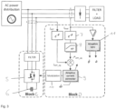
- Fig. 1 shows a block diagram of a typical 18-pulse rectifier unit including the Autotransformer Rectifier Unit (ATRU), diode bridges and Interphase Transformers (IPTs).
- ATRU Autotransformer Rectifier Unit
- IPTs Interphase Transformers
- the output voltage of the multi-phase winding is rectified by a number of basic 6-pulse rectifier cells 2, thus improving the input current total harmonic distortion.
- the input current quality is limited by the number of 6-pulse stages. If additional 6-pulse cells are added to achieve a lower distortion, this results in an undesirable increase in the weight of the rectifier unit.
- the aim of the present disclosure is to provide a power converter that mitigates harmonic distortion and adds redundancy to the rectification stage with either fixed frequency or variable frequency AC power source, while avoiding the use of the autotransformer unit and the IPT, thus reducing the rectifier unit weight compared with the existing ATRU solution.
- the invention provides an aircraft electrical power system according to claim 1. Preferred embodiments are defined in the dependent claims.
- n/6 6-pulse diode bridges where n is an integer
- the ATRU and the use of n/6 6-pulse diode bridges is substituted by a single 6-pulse rectifier cell connected directly to the AC power distribution system (which can be fixed or variable frequency) and an active power filter (APF) connected in parallel to the rectifier cell, as a shunt APF.
- AC power distribution system which can be fixed or variable frequency
- APF active power filter
- the shunt APF is designed to locally compensate for the non-linear current harmonics, thus allowing the harmonics content of the current drawn by the power distribution system to be below the permitted maximum.
- the shunt APF control includes an adaptive control algorithm able to assure proper current harmonics compensation within a predefined frequency variation range, typically 350 - 800 Hz.
- the active filter is arranged to modify the amplitude and/or phase characteristics of the current provided by the AC power signal so as to compensate for harmonic currents drawn by the load.
- the proposed power converter unit is shown in Figure 2 , where block A and block B represent the main parts of the unit. Both block A and block B are connected to the AC power distribution system.
- Block A is a rectifier composed of a 3-phase diode bridge 3, a filter 4 and the load.
- the current drawn by the block A contains harmonics from the fundamental AC power distribution frequency that need to be filtered out to meet power quality requirements.
- the current solution is to use an ATRU to eliminate or minimise harmonics.
- the present disclosure presents an alternative solution.
- a shunt active power filter or APF depicted in block B is proposed in this disclosure.
- the APF is composed by at least six semiconductors 5 operated in switching mode and a storage element 6, which could be a capacitor.
- the APF is controlled so that it locally injects the harmonics other than the fundamental frequency drawn by the block A, so that a cancelling-out effect occurs and the current provided by the AC power distribution contains only the fundamental frequency.
- the APF shown in block B includes an adaptive control algorithm which is able to compensate the undesired harmonics drawn by block A no matter what the variation in the frequency of the AC power distribution main harmonic is, which typically varies from 350 - 800 Hz in a variable frequency AC power supply system.
- Block C represents the power stage comprising the semiconductors 5 and storage element 6 explained in the previous section
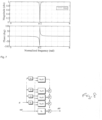
- block D represents the control architecture of the control algorithm to achieve the harmonics compensation regardless of frequency variations of the AC power distribution system.
- the preferred control algorithm is composed by:
- the adaptive features of block D are provided by the adaptive grid synchronization algorithm 11 and the adaptive current controller 9 as described further below.
- the adaptive grid synchronization algorithm 11 is responsible for synchronising the shunt APF with the AC power distribution system. This algorithm is based on the standard Synchronous Reference Frame Phase Locked Loop (SRF-PLL) and adds adaptive filtering features to cope with the lack of synchronization accuracy that occurs when the AC power distribution voltage is polluted with voltage harmonics and its frequency is not fixed.
- SRF-PLL Synchronous Reference Frame Phase Locked Loop
- ALSRF-PLL Adaptive Lattice Synchronous Reference Frame Phase Locked Loop
- Figure 4 The ALSRF-PLL has been described in " An adaptive synchronous-Reference-Frame Phase-Locked-Loop for Power Quality Improvement in a Polluted Utility Grid.”
- F. Gonzalez-Espin, E. Figueres, and G. Garcera IEEE Transactions on Industrial Electronics, vol. 59, pp. 2718-2731, 2012 , and is composed of three main blocks:
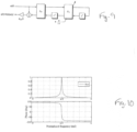
- the adaptive notch filters 12 are preferably implemented by using the Schur-lattice IIR structure shown in Figure 5 , which carries out the rotation over the transfer function involving the filtering process shown in Figure 6 .
- the transfer function of the notch filter is shown in equation (1), and can be derived from Block H, where the normalized center frequency, ⁇ 0 , and the bandwidth, BW , can be adjusted by equation (2) and (3), respectively.
- the Gradient Adaptive Lattice (GAL) recursive algorithm can be used to automatically adjust in real-time the parameter ⁇ 1 , so that the center frequency of the filters are able to filter out the undesired variable frequency harmonics.
- GAL Gradient Adaptive Lattice
- An important feature of the Schur Lattice filter with GAL recursive algorithm is that the filter does not need a reference to adaptively tune its center frequency, which is of great importance when filtering out the ALSRF-PLL harmonics.
- Block I in Figure 5 implements the GAL algorithms expressed in equation (4), where ⁇ is the adaptation gain.
- the adaptive current controller is preferably based on the control architecture shown in Figure 8 .
- the Proportional+Lattice controller is composed of a gain, K D , in parallel with harmonic compensators, H hn (z).
- the harmonic compensators are band-pass filters tuned at the corresponding harmonics (h1 to hn in the figure).
- the band-pass filters offer a high gain in the control loop, so the shunt APF is able to accurately compensate for the harmonics drawn by the non-linear load.
- the information about the frequency of the AC voltage estimated by the Adaptive grid synchronization algorithm 11 (ALSRF-PLL) is used to adjust in real time the band-pass filter center frequency, so that the tracking of the harmonics is accurate through all of the frequency range of operation, typically 350 - 800 Hz.
- Schur Lattice IIR band-pass Filter structure shown in Figure 9 is preferably used in this disclosure and allows implementing an inherently stable IIR filter, which is of paramount importance when adjusting coefficients in real-time, so that the stability of the closed loop APF current control is not compromised by the coefficient adaptation process.
- the system of this disclosure by doing away with the ATRU, reduces the weight of the rectifier unit.
- the shunt APF is digitally controlled and can use high frequency pulse with modulation (PWM) or other switching modulation techniques and an adaptive control algorithm, which allows very accurate fixed or variable frequency harmonics compensation.
- PWM pulse with modulation
- the provision of the shunt APF in parallel with the rectifier also provides redundancy - i.e. if the APF fails, the rectifier will continue to operate, albeit in a degraded mode, so that the load will still receive power even though the current provided by the AC power system will be of a lower quality with more harmonic distortion.
Landscapes
- Engineering & Computer Science (AREA)
- Power Engineering (AREA)
- Supply And Distribution Of Alternating Current (AREA)
- Rectifiers (AREA)
- Power Conversion In General (AREA)
Claims (8)
- Elektrisches Stromversorgungssystem eines Flugzeugs, umfassend eine Leistungswandlereinheit (Blöcke A-F), umfassend eine einzelne 6-Puls-Gleichrichterzelle (3), die dazu konfiguriert ist, einen AC-Eingang in dem Bereich von 350-800 Hz von einer AC-Leistungsquelle mit 115 V oder 230 V zu empfangen, und einen aktiven Leistungsfilter (Block B, C), der als ein Shunt zwischen dem AC-Eingang und der 6-Puls-Gleichrichterzelle (3) verbunden ist;wobei der aktive Leistungsfilter einen Steueralgorithmus umfasst, der dazu konfiguriert ist, die Entfernung von Stromharmonischenfrequenzen aus dem AC-Eingang zu veranlassen, jedoch nicht von einer Stromgrundfrequenz des AC-Eingangs; wobei der Steueralgorithmus Folgendes umfasst:- eine Umwandlungsstufe (7), die dazu konfiguriert ist, erfasste AC-Eingangsströme aus einem natürlichen Referenzrahmen in einen Synchronreferenzrahmen zu drehen;- einen Hochpassfilter (8), der dazu konfiguriert ist, eine Grundharmonische aus einem erfassten Laststrom herauszufiltern und lediglich Harmonische der Grundschwingung an einem Ausgang bereitzustellen;- adaptive Stromsteuermittel (9), die dazu konfiguriert sind, eine hohe Steuerschleifenverstärkung bei der Frequenz der Harmonischen von dem Ausgang des Hochpassfilters (8) ungeachtet der Grundfrequenz der AC-Leistungsquelle bereitzustellen;einen Pulsbreitenmodulator oder einen Raumvektormodulator (10), der dazu konfiguriert ist, den Ausgang der adaptiven Stromsteuermittel (9) zu modulieren; undeinen Synchronisierungsalgorithmus, der dazu konfiguriert ist, adaptive Gitter-Synchronreferenzrahmen-Phasenregelschleife-Synchronisierung (Adaptive Lattice Synchronous Reference Frame Phase Locked Loop, ALSRF-PLL) (11) zum Synchronisieren des aktiven Leistungsfilters (Block B, C) mit der AC-Stromquelle zu verwenden.
- Stromversorgungssystem nach Anspruch 1, bei dem die 6-Puls-Gleichrichterzelle (3) dazu konfiguriert ist, den AC-Eingang von einer AC-Leistungsquelle mit feststehender oder variabler Frequenz zu empfangen.
- Stromversorgungssystem nach Anspruch 1 oder 2, wobei die 6-Puls-Gleichrichterzelle (3) eine 3-phasige Diodenbrücke umfasst.
- Stromversorgungssystem nach einem der vorhergehenden Ansprüche, wobei der aktive Leistungsfilter (Block B, C) eine Vielzahl von Halbleiterschaltern (5) und ein Speicherelement (6) umfasst.
- Stromversorgungssystem nach einem der vorhergehenden Ansprüche, wobei das adaptive Stromsteuermittel (9) adaptive Bandpassfilter beinhaltet, die dazu konfiguriert sind, eine Schur-Gitter-IIR-Struktur zu verwenden.
- Stromversorgungssystem nach Anspruch 1, wobei der Synchronisierungsalgorithmus (11) Folgendes umfasst:- Mittel zum Umwandeln eines AC-Spannungsvektors des AC-Eingangs in eine Synchronreferenzphase;- einen Regler und einen Integrator, die in Reihe verbunden sind, die dazu konfiguriert sind, einen Eingang für die Mittel zum Umwandeln bereitzustellen;- eine Vielzahl von adaptiven Bandsperrfiltern (12), die dazu konfiguriert sind, unerwünschten Harmonischengehalt mit variabler Frequenz aus der erfassten AC-Eingangsspannung auszusondern, ungeachtet der Grundfrequenz der AC-Leistungsquelle.
- Stromversorgungssystem nach Anspruch 6, wobei die Vielzahl von adaptiven Bandsperrfiltern (12) dazu konfiguriert ist, eine Schur-Gitter-IIR-Struktur zu verwenden.
- Stromversorgungssystem nach Anspruch 7, wobei die Zentrumsfrequenzen der Vielzahl von Bandsperrfiltern (12) dazu konfiguriert sind, in Echtzeit angepasst zu werden, um Frequenzänderungen der AC-Leistungsquelle unter Verwendung eines Gradientengitteralgorithmus zu verfolgen.
Priority Applications (2)
| Application Number | Priority Date | Filing Date | Title |
|---|---|---|---|
| EP16153595.0A EP3200330B1 (de) | 2016-02-01 | 2016-02-01 | Reduktion von harmonischen am eingang einer gleichrichtereinheit in einem elektrischen stromversorgungssystem eines flugzeugs |
| US15/421,766 US10050549B2 (en) | 2016-02-01 | 2017-02-01 | Power converter unit including a rectifier and an active power filter |
Applications Claiming Priority (1)
| Application Number | Priority Date | Filing Date | Title |
|---|---|---|---|
| EP16153595.0A EP3200330B1 (de) | 2016-02-01 | 2016-02-01 | Reduktion von harmonischen am eingang einer gleichrichtereinheit in einem elektrischen stromversorgungssystem eines flugzeugs |
Publications (2)
| Publication Number | Publication Date |
|---|---|
| EP3200330A1 EP3200330A1 (de) | 2017-08-02 |
| EP3200330B1 true EP3200330B1 (de) | 2024-12-25 |
Family
ID=55272395
Family Applications (1)
| Application Number | Title | Priority Date | Filing Date |
|---|---|---|---|
| EP16153595.0A Active EP3200330B1 (de) | 2016-02-01 | 2016-02-01 | Reduktion von harmonischen am eingang einer gleichrichtereinheit in einem elektrischen stromversorgungssystem eines flugzeugs |
Country Status (2)
| Country | Link |
|---|---|
| US (1) | US10050549B2 (de) |
| EP (1) | EP3200330B1 (de) |
Families Citing this family (11)
| Publication number | Priority date | Publication date | Assignee | Title |
|---|---|---|---|---|
| CN107332245A (zh) * | 2017-08-29 | 2017-11-07 | 云南电力试验研究院(集团)有限公司 | 一种谐波与无功的治理方法 |
| US10541601B2 (en) * | 2017-10-30 | 2020-01-21 | University Of Florida Research Foundation, Inc. | EMI energy mitigation |
| US10998899B2 (en) | 2017-10-30 | 2021-05-04 | University Of Florida Research Foundation, Inc. | EMI energy mitigation |
| US20190326828A1 (en) * | 2018-04-19 | 2019-10-24 | Hamilton Sundstrand Corporation | Fault tolerant ac rectification |
| US10901026B2 (en) * | 2018-09-18 | 2021-01-26 | Tci, Llc | Passive harmonic filter power quality monitor and communications device |
| CN109193658B (zh) * | 2018-10-31 | 2019-07-09 | 国网江苏省电力有限公司苏州供电分公司 | 一种利用有源电力滤波器进行谐波电流补偿的方法 |
| CN109599868B (zh) * | 2018-11-28 | 2022-05-20 | 广州锐翔电力科技有限公司 | 一种有源滤波器输出电流的控制系统及方法 |
| EP4160891A1 (de) * | 2021-10-04 | 2023-04-05 | Hamilton Sundstrand Corporation | Oberschwingungskompensator für aktiven gleichrichter |
| EP4212891A1 (de) | 2022-01-08 | 2023-07-19 | Goodrich Aerospace Services Private Limited | Fehlererkennungsverfahren und systeme dafür |
| JP2024045981A (ja) * | 2022-09-22 | 2024-04-03 | 東芝キヤリア株式会社 | 高調波抑制装置 |
| US20240405572A1 (en) * | 2023-05-31 | 2024-12-05 | Hamilton Sundstrand Corporation | Reactive Current Injenction for Active Aerospace Rectification |
Citations (1)
| Publication number | Priority date | Publication date | Assignee | Title |
|---|---|---|---|---|
| GB2519590A (en) * | 2013-10-28 | 2015-04-29 | Mohamad Hussein Taha | Single phase parallel active filter for aircraft applications |
Family Cites Families (2)
| Publication number | Priority date | Publication date | Assignee | Title |
|---|---|---|---|---|
| CA2838384C (en) * | 2013-01-02 | 2022-11-22 | Tci, Llc | Paralleling of active filters with independent controls |
| US9584039B2 (en) * | 2014-05-27 | 2017-02-28 | Hamilton Sundstrand Corporation | Regulated AC-DC hybrid rectifier |
-
2016
- 2016-02-01 EP EP16153595.0A patent/EP3200330B1/de active Active
-
2017
- 2017-02-01 US US15/421,766 patent/US10050549B2/en active Active
Patent Citations (1)
| Publication number | Priority date | Publication date | Assignee | Title |
|---|---|---|---|---|
| GB2519590A (en) * | 2013-10-28 | 2015-04-29 | Mohamad Hussein Taha | Single phase parallel active filter for aircraft applications |
Non-Patent Citations (1)
| Title |
|---|
| VENTURINI R P ET AL: "Adaptive Selective Compensation for Variable Frequency Active Power Filters in More Electrical Aircraft", IEEE TRANSACTIONS ON AEROSPACE AND ELECTRONIC SYSTEMS, IEEE SERVICE CENTER, PISCATAWAY, NJ, US, vol. 48, no. 2, 1 April 2012 (2012-04-01), pages 1319 - 1328, XP011440815, ISSN: 0018-9251, DOI: 10.1109/TAES.2012.6178064 * |
Also Published As
| Publication number | Publication date |
|---|---|
| US10050549B2 (en) | 2018-08-14 |
| EP3200330A1 (de) | 2017-08-02 |
| US20170222571A1 (en) | 2017-08-03 |
Similar Documents
| Publication | Publication Date | Title |
|---|---|---|
| EP3200330B1 (de) | Reduktion von harmonischen am eingang einer gleichrichtereinheit in einem elektrischen stromversorgungssystem eines flugzeugs | |
| US6950322B2 (en) | Regulated AC to DC converter for aerospace applications | |
| US6650557B2 (en) | 18-pulse rectification system using a wye-connected autotransformer | |
| Jensen et al. | A new control method for 400 Hz ground power units for airplanes | |
| Thomas et al. | Design and performance of active power filters | |
| Hu et al. | Design considerations for DSP-controlled 400 Hz shunt active power filter in an aircraft power system | |
| EP3497782B1 (de) | Zweistufige steuerung eines wandlersystems mit schwebenden zellen | |
| Chen et al. | A novel parallel configured 48-pulse autotransformer rectifier for aviation application | |
| Mihalache | DSP control of 400 Hz inverters for aircraft applications | |
| Liang et al. | A solid state variable capacitor with minimum DC capacitance | |
| Heo et al. | Robust predictive current control of a grid-connected inverter with harmonics compensation | |
| US20230170818A1 (en) | Power conversion system | |
| US12230964B2 (en) | DC power supply device and railway substation incorporating it | |
| Peng et al. | A study of active power filters using quad-series voltage-source PWM converters for harmonic compensation | |
| JP2002359927A (ja) | フィルタ装置 | |
| Cho et al. | LCL filter design and control for grid-connected PWM converter | |
| US6208540B1 (en) | Combined power inverter and auxilliary power supply using null vector modulation | |
| Rajesh et al. | A shunt active power filter for 12 pulse converter using source current detection approach | |
| KR20130092539A (ko) | 교류 모터를 제어하는 제어 장치 및 방법 | |
| JP3128742B2 (ja) | 電源装置 | |
| Taha | Power electronics application for more electric aircraft | |
| Liu et al. | LCL+ L filter for three-phase four-wire high power density converter | |
| Taha | Active rectifier using DQ vector control for aircraft power system | |
| Akihiro et al. | Unbalanced load compensation for solid-state transformer using smoothing capacitors of cascaded h-bridges as energy buffer | |
| Frangopol et al. | A Solution for Reducing Harmonic Regime and Reactive Power Absorbed by a Cycloconverter |
Legal Events
| Date | Code | Title | Description |
|---|---|---|---|
| PUAI | Public reference made under article 153(3) epc to a published international application that has entered the european phase |
Free format text: ORIGINAL CODE: 0009012 |
|
| STAA | Information on the status of an ep patent application or granted ep patent |
Free format text: STATUS: THE APPLICATION HAS BEEN PUBLISHED |
|
| AK | Designated contracting states |
Kind code of ref document: A1 Designated state(s): AL AT BE BG CH CY CZ DE DK EE ES FI FR GB GR HR HU IE IS IT LI LT LU LV MC MK MT NL NO PL PT RO RS SE SI SK SM TR |
|
| AX | Request for extension of the european patent |
Extension state: BA ME |
|
| STAA | Information on the status of an ep patent application or granted ep patent |
Free format text: STATUS: REQUEST FOR EXAMINATION WAS MADE |
|
| 17P | Request for examination filed |
Effective date: 20180202 |
|
| RBV | Designated contracting states (corrected) |
Designated state(s): AL AT BE BG CH CY CZ DE DK EE ES FI FR GB GR HR HU IE IS IT LI LT LU LV MC MK MT NL NO PL PT RO RS SE SI SK SM TR |
|
| STAA | Information on the status of an ep patent application or granted ep patent |
Free format text: STATUS: EXAMINATION IS IN PROGRESS |
|
| 17Q | First examination report despatched |
Effective date: 20200706 |
|
| RAP1 | Party data changed (applicant data changed or rights of an application transferred) |
Owner name: HAMILTON SUNDSTRAND CORPORATION |
|
| GRAP | Despatch of communication of intention to grant a patent |
Free format text: ORIGINAL CODE: EPIDOSNIGR1 |
|
| STAA | Information on the status of an ep patent application or granted ep patent |
Free format text: STATUS: GRANT OF PATENT IS INTENDED |
|
| RIC1 | Information provided on ipc code assigned before grant |
Ipc: H02M 1/00 20060101ALI20240710BHEP Ipc: H02M 1/15 20060101ALI20240710BHEP Ipc: H02J 3/01 20060101ALI20240710BHEP Ipc: H02M 1/12 20060101AFI20240710BHEP |
|
| INTG | Intention to grant announced |
Effective date: 20240808 |
|
| GRAS | Grant fee paid |
Free format text: ORIGINAL CODE: EPIDOSNIGR3 |
|
| GRAA | (expected) grant |
Free format text: ORIGINAL CODE: 0009210 |
|
| STAA | Information on the status of an ep patent application or granted ep patent |
Free format text: STATUS: THE PATENT HAS BEEN GRANTED |
|
| AK | Designated contracting states |
Kind code of ref document: B1 Designated state(s): AL AT BE BG CH CY CZ DE DK EE ES FI FR GB GR HR HU IE IS IT LI LT LU LV MC MK MT NL NO PL PT RO RS SE SI SK SM TR |
|
| REG | Reference to a national code |
Ref country code: GB Ref legal event code: FG4D |
|
| REG | Reference to a national code |
Ref country code: CH Ref legal event code: EP |
|
| REG | Reference to a national code |
Ref country code: DE Ref legal event code: R096 Ref document number: 602016090710 Country of ref document: DE |
|
| REG | Reference to a national code |
Ref country code: IE Ref legal event code: FG4D |
|
| REG | Reference to a national code |
Ref country code: LT Ref legal event code: MG9D |
|
| PG25 | Lapsed in a contracting state [announced via postgrant information from national office to epo] |
Ref country code: HR Free format text: LAPSE BECAUSE OF FAILURE TO SUBMIT A TRANSLATION OF THE DESCRIPTION OR TO PAY THE FEE WITHIN THE PRESCRIBED TIME-LIMIT Effective date: 20241225 |
|
| PGFP | Annual fee paid to national office [announced via postgrant information from national office to epo] |
Ref country code: DE Payment date: 20250122 Year of fee payment: 10 |
|
| PG25 | Lapsed in a contracting state [announced via postgrant information from national office to epo] |
Ref country code: FI Free format text: LAPSE BECAUSE OF FAILURE TO SUBMIT A TRANSLATION OF THE DESCRIPTION OR TO PAY THE FEE WITHIN THE PRESCRIBED TIME-LIMIT Effective date: 20241225 |
|
| PG25 | Lapsed in a contracting state [announced via postgrant information from national office to epo] |
Ref country code: BG Free format text: LAPSE BECAUSE OF FAILURE TO SUBMIT A TRANSLATION OF THE DESCRIPTION OR TO PAY THE FEE WITHIN THE PRESCRIBED TIME-LIMIT Effective date: 20241225 |
|
| PG25 | Lapsed in a contracting state [announced via postgrant information from national office to epo] |
Ref country code: NO Free format text: LAPSE BECAUSE OF FAILURE TO SUBMIT A TRANSLATION OF THE DESCRIPTION OR TO PAY THE FEE WITHIN THE PRESCRIBED TIME-LIMIT Effective date: 20250325 |
|
| PG25 | Lapsed in a contracting state [announced via postgrant information from national office to epo] |
Ref country code: GR Free format text: LAPSE BECAUSE OF FAILURE TO SUBMIT A TRANSLATION OF THE DESCRIPTION OR TO PAY THE FEE WITHIN THE PRESCRIBED TIME-LIMIT Effective date: 20250326 Ref country code: LV Free format text: LAPSE BECAUSE OF FAILURE TO SUBMIT A TRANSLATION OF THE DESCRIPTION OR TO PAY THE FEE WITHIN THE PRESCRIBED TIME-LIMIT Effective date: 20241225 |
|
| PGFP | Annual fee paid to national office [announced via postgrant information from national office to epo] |
Ref country code: FR Payment date: 20250122 Year of fee payment: 10 |
|
| PGFP | Annual fee paid to national office [announced via postgrant information from national office to epo] |
Ref country code: GB Payment date: 20250123 Year of fee payment: 10 |
|
| PG25 | Lapsed in a contracting state [announced via postgrant information from national office to epo] |
Ref country code: RS Free format text: LAPSE BECAUSE OF FAILURE TO SUBMIT A TRANSLATION OF THE DESCRIPTION OR TO PAY THE FEE WITHIN THE PRESCRIBED TIME-LIMIT Effective date: 20250325 |
|
| REG | Reference to a national code |
Ref country code: NL Ref legal event code: MP Effective date: 20241225 |
|
| PG25 | Lapsed in a contracting state [announced via postgrant information from national office to epo] |
Ref country code: NL Free format text: LAPSE BECAUSE OF FAILURE TO SUBMIT A TRANSLATION OF THE DESCRIPTION OR TO PAY THE FEE WITHIN THE PRESCRIBED TIME-LIMIT Effective date: 20241225 |
|
| REG | Reference to a national code |
Ref country code: AT Ref legal event code: MK05 Ref document number: 1755021 Country of ref document: AT Kind code of ref document: T Effective date: 20241225 |
|
| PG25 | Lapsed in a contracting state [announced via postgrant information from national office to epo] |
Ref country code: SM Free format text: LAPSE BECAUSE OF FAILURE TO SUBMIT A TRANSLATION OF THE DESCRIPTION OR TO PAY THE FEE WITHIN THE PRESCRIBED TIME-LIMIT Effective date: 20241225 |
|
| PG25 | Lapsed in a contracting state [announced via postgrant information from national office to epo] |
Ref country code: PL Free format text: LAPSE BECAUSE OF FAILURE TO SUBMIT A TRANSLATION OF THE DESCRIPTION OR TO PAY THE FEE WITHIN THE PRESCRIBED TIME-LIMIT Effective date: 20241225 |
|
| PG25 | Lapsed in a contracting state [announced via postgrant information from national office to epo] |
Ref country code: ES Free format text: LAPSE BECAUSE OF FAILURE TO SUBMIT A TRANSLATION OF THE DESCRIPTION OR TO PAY THE FEE WITHIN THE PRESCRIBED TIME-LIMIT Effective date: 20241225 |
|
| PG25 | Lapsed in a contracting state [announced via postgrant information from national office to epo] |
Ref country code: IS Free format text: LAPSE BECAUSE OF FAILURE TO SUBMIT A TRANSLATION OF THE DESCRIPTION OR TO PAY THE FEE WITHIN THE PRESCRIBED TIME-LIMIT Effective date: 20250425 |
|
| PG25 | Lapsed in a contracting state [announced via postgrant information from national office to epo] |
Ref country code: PT Free format text: LAPSE BECAUSE OF FAILURE TO SUBMIT A TRANSLATION OF THE DESCRIPTION OR TO PAY THE FEE WITHIN THE PRESCRIBED TIME-LIMIT Effective date: 20250428 |
|
| PG25 | Lapsed in a contracting state [announced via postgrant information from national office to epo] |
Ref country code: EE Free format text: LAPSE BECAUSE OF FAILURE TO SUBMIT A TRANSLATION OF THE DESCRIPTION OR TO PAY THE FEE WITHIN THE PRESCRIBED TIME-LIMIT Effective date: 20241225 |
|
| PG25 | Lapsed in a contracting state [announced via postgrant information from national office to epo] |
Ref country code: RO Free format text: LAPSE BECAUSE OF FAILURE TO SUBMIT A TRANSLATION OF THE DESCRIPTION OR TO PAY THE FEE WITHIN THE PRESCRIBED TIME-LIMIT Effective date: 20241225 Ref country code: AT Free format text: LAPSE BECAUSE OF FAILURE TO SUBMIT A TRANSLATION OF THE DESCRIPTION OR TO PAY THE FEE WITHIN THE PRESCRIBED TIME-LIMIT Effective date: 20241225 |
|
| PG25 | Lapsed in a contracting state [announced via postgrant information from national office to epo] |
Ref country code: SK Free format text: LAPSE BECAUSE OF FAILURE TO SUBMIT A TRANSLATION OF THE DESCRIPTION OR TO PAY THE FEE WITHIN THE PRESCRIBED TIME-LIMIT Effective date: 20241225 |
|
| PG25 | Lapsed in a contracting state [announced via postgrant information from national office to epo] |
Ref country code: CZ Free format text: LAPSE BECAUSE OF FAILURE TO SUBMIT A TRANSLATION OF THE DESCRIPTION OR TO PAY THE FEE WITHIN THE PRESCRIBED TIME-LIMIT Effective date: 20241225 |
|
| PG25 | Lapsed in a contracting state [announced via postgrant information from national office to epo] |
Ref country code: IT Free format text: LAPSE BECAUSE OF FAILURE TO SUBMIT A TRANSLATION OF THE DESCRIPTION OR TO PAY THE FEE WITHIN THE PRESCRIBED TIME-LIMIT Effective date: 20241225 |
|
| PG25 | Lapsed in a contracting state [announced via postgrant information from national office to epo] |
Ref country code: SE Free format text: LAPSE BECAUSE OF FAILURE TO SUBMIT A TRANSLATION OF THE DESCRIPTION OR TO PAY THE FEE WITHIN THE PRESCRIBED TIME-LIMIT Effective date: 20241225 |
|
| PG25 | Lapsed in a contracting state [announced via postgrant information from national office to epo] |
Ref country code: MC Free format text: LAPSE BECAUSE OF FAILURE TO SUBMIT A TRANSLATION OF THE DESCRIPTION OR TO PAY THE FEE WITHIN THE PRESCRIBED TIME-LIMIT Effective date: 20241225 |
|
| REG | Reference to a national code |
Ref country code: DE Ref legal event code: R097 Ref document number: 602016090710 Country of ref document: DE |
|
| REG | Reference to a national code |
Ref country code: CH Ref legal event code: PL |
|
| PG25 | Lapsed in a contracting state [announced via postgrant information from national office to epo] |
Ref country code: DK Free format text: LAPSE BECAUSE OF FAILURE TO SUBMIT A TRANSLATION OF THE DESCRIPTION OR TO PAY THE FEE WITHIN THE PRESCRIBED TIME-LIMIT Effective date: 20241225 |
|
| PG25 | Lapsed in a contracting state [announced via postgrant information from national office to epo] |
Ref country code: LU Free format text: LAPSE BECAUSE OF NON-PAYMENT OF DUE FEES Effective date: 20250201 |
|
| PG25 | Lapsed in a contracting state [announced via postgrant information from national office to epo] |
Ref country code: CH Free format text: LAPSE BECAUSE OF NON-PAYMENT OF DUE FEES Effective date: 20250228 |
|
| PLBE | No opposition filed within time limit |
Free format text: ORIGINAL CODE: 0009261 |
|
| STAA | Information on the status of an ep patent application or granted ep patent |
Free format text: STATUS: NO OPPOSITION FILED WITHIN TIME LIMIT |
|
| 26N | No opposition filed |
Effective date: 20250926 |
|
| REG | Reference to a national code |
Ref country code: BE Ref legal event code: MM Effective date: 20250228 |
|
| PG25 | Lapsed in a contracting state [announced via postgrant information from national office to epo] |
Ref country code: BE Free format text: LAPSE BECAUSE OF NON-PAYMENT OF DUE FEES Effective date: 20250228 |
|
| PG25 | Lapsed in a contracting state [announced via postgrant information from national office to epo] |
Ref country code: IE Free format text: LAPSE BECAUSE OF NON-PAYMENT OF DUE FEES Effective date: 20250201 |