EP3199708A1 - Excavation enclosure and method for creating an excavation enclosure - Google Patents
Excavation enclosure and method for creating an excavation enclosure Download PDFInfo
- Publication number
- EP3199708A1 EP3199708A1 EP16153356.7A EP16153356A EP3199708A1 EP 3199708 A1 EP3199708 A1 EP 3199708A1 EP 16153356 A EP16153356 A EP 16153356A EP 3199708 A1 EP3199708 A1 EP 3199708A1
- Authority
- EP
- European Patent Office
- Prior art keywords
- receiving bore
- sealing element
- joint
- wall
- vertical
- Prior art date
- Legal status (The legal status is an assumption and is not a legal conclusion. Google has not performed a legal analysis and makes no representation as to the accuracy of the status listed.)
- Granted
Links
Images


Classifications
-
- E—FIXED CONSTRUCTIONS
- E02—HYDRAULIC ENGINEERING; FOUNDATIONS; SOIL SHIFTING
- E02D—FOUNDATIONS; EXCAVATIONS; EMBANKMENTS; UNDERGROUND OR UNDERWATER STRUCTURES
- E02D5/00—Bulkheads, piles, or other structural elements specially adapted to foundation engineering
- E02D5/02—Sheet piles or sheet pile bulkheads
- E02D5/14—Sealing joints between adjacent sheet piles
-
- E—FIXED CONSTRUCTIONS
- E02—HYDRAULIC ENGINEERING; FOUNDATIONS; SOIL SHIFTING
- E02D—FOUNDATIONS; EXCAVATIONS; EMBANKMENTS; UNDERGROUND OR UNDERWATER STRUCTURES
- E02D17/00—Excavations; Bordering of excavations; Making embankments
- E02D17/02—Foundation pits
-
- E—FIXED CONSTRUCTIONS
- E02—HYDRAULIC ENGINEERING; FOUNDATIONS; SOIL SHIFTING
- E02D—FOUNDATIONS; EXCAVATIONS; EMBANKMENTS; UNDERGROUND OR UNDERWATER STRUCTURES
- E02D19/00—Keeping dry foundation sites or other areas in the ground
- E02D19/02—Restraining of open water
Definitions
- the invention relates to a method for constructing a construction pit enclosure in which a substantially vertical enclosure wall of slotted wall panels is created in the ground, the vertical joints are sealed by means of a joint sealing strip, the floor is dug within the enclosure wall, and a substantially horizontal floor slab is provided, which adjoins the enclosing wall, according to the preamble of claim 1.
- the invention further relates to a construction pit enclosure having a substantially vertical enclosure wall in the bottom formed by slot wall panels whose vertical joints are sealed by a joint sealing strip and a substantially horizontal floor plate adjacent to the enclosure wall and sealing the excavation downwardly the preamble of claim 10.
- the invention relates to a sealing element for such a method and such Baugrubenumsch proof.
- the enclosure wall is composed of prefabricated reinforced concrete parts, which are arranged vertically one above the other and clamped together.
- an enclosure wall is first created in the ground.
- the enclosure wall is created from individual stitches or Schlitzwandpanelen, which form an annularly closed Umsch widelyungswand together. Subsequently, the soil is excavated within the enclosure wall to form the excavation.
- a bottom plate In a lower area, a bottom plate is provided, which seals the pit against a groundwater passage from below.
- the bottom plate may be formed by a water-barrier bottom layer or made as a structural part. Between the vertical Schlitzwandpanelen form joints, which represent leaking areas.
- a generic method for producing a trench wall for a Baugrubenumschbine is described in detail.
- a slot is first created in the ground, which is filled with a curable composition.
- a formwork element is used in the not yet cured mass, which is provided with a joint sealing tape.
- the formwork element is removed leaving the joint sealing strip in a central area along the vertical butt joint between the two trench wall panels thus created.
- the joint sealing tape ensures that no water flows laterally into the excavated excavation along the joint between the two slotted wall panels.
- a horizontal seal may be provided along the horizontal butt joint, which is formed between the bottom plate and the surrounding enclosing wall. That's how it describes EP 2 549 021 B1 a water reservoir with a shaft wall made of slotted wall panels and a concrete floor slab. The bottom plate is connected via dowels or a projection with the shaft wall. In the corner region between shaft wall and bottom plate, a horizontal annular sealing device is provided.
- joint sealing strips and sealing devices are often not sufficient to seal a construction pit enclosure thus created against water penetration.
- the invention has for its object to provide a Baugrubenumsch admiration and a method for creating a Baugrubenumschiff, which is made possible in an efficient manner, a particularly dense Baugrubenumschmother. It is another object of the invention to provide a sealing element for this purpose.
- the object is achieved on the one hand by a method having the features of claim 1, a construction pit enclosure having the features of claim 10 or by a sealing element having the features of claim 13.
- a method having the features of claim 1 a construction pit enclosure having the features of claim 10 or by a sealing element having the features of claim 13.
- Preferred embodiments are given in the respective dependent claims.
- the inventive method for creating a Baugrubenumsch well is characterized in that at least one vertical butt joint between two adjacent Schlitzwandpanelen in the Umsch conductedungswand a extending to the joint sealing tape receiving bore is introduced and that in the receiving bore a sealing element is introduced to form a horizontal seal.
- the invention is based on the finding that when water enters a generously constructed excavation enclosure, the water substantially penetrates along the vertical joints in a region which extends between a substantially centrally located joint tape between the diaphragm wall panels and the floor slab.
- the water can rise due to capillary forces vertically in the butt joint upwards and thus penetrate past the bottom plate in the excavation.
- an approximately horizontal receiving bore is introduced at the vertical butt joint between two adjacent Schlitzwandpanelen in the Umsch thoroughlyungswand, which extends to the joint sealing tape.
- a sealing element is then introduced, which seals the receiving bore and thus the critical area of the vertical butt joint between the vertical joint sealing strip and the adjacent base plate.
- a preferred embodiment of the invention is that the at least one receiving bore is introduced at the level of the bottom plate in the Umsch widelyungswand.
- the receiving bore can preferably be created horizontally or at an oblique angle. This allows the shortest possible and thus efficient bore.
- the bottom plate may be formed by a water-barrier bottom layer, which is natural or sealed by gel injections, or as a structural part, such as concrete.
- the receiving bore can be introduced directly over an existing base plate in the Umsch solvedungswand.
- the bottom plate is created and that the at least one receiving bore is introduced before the bottom plate is produced.
- the receiving bore can be created in particular at the height level of the bottom plate. After sealing, a bottom plate can then be made separately, such as by concreting.
- the receiving bore is introduced from an inner side of the enclosing wall to the vertical joint sealing tape or beyond in the Umsch widelyungswand.
- the receiving bore extends horizontally or at a certain angle of inclination until the receiving bore comes close to the joint sealing tape or this preferably contacted.
- the receiving bore thus extends transversely to the vertical butt joint, so that after introduction of the sealing element capillary rising of water between the vertical joint sealing strip and the bottom plate is prevented.
- the receiving bore can be introduced beyond the sealing strip into the enclosing wall. In this case, the joint sealing strip is removed during the introduction of the bore in this area and the sealing function is then taken over by the introduced sealing element.
- the receiving bore to the outside of the enclosing wall so that the sealing band extends transversely through the enclosure wall and the vertical butt joint between the two adjacent slot wall panels is sealed over the entire panel width.
- the bottom plate adjoins the enclosing wall to form a horizontal butt joint, which is sealed with a horizontal seal.
- the horizontal seal may be an annular sealing device, in particular a sealing tape which has been folded over the corner.
- the horizontal seal extends annularly along the edge of the entire bottom plate.
- the vertical joint sealing tape can be arranged between the individual slot wall panels in any suitable manner.
- the slot wall panels also called sealing wall panels, can be made in any way by creating and filling a hole in the ground, such as by drilling.
- the slot or sealing wall thus produced may be referred to as a bored pile wall.
- a preferred embodiment of the invention is that the trench wall panels are made progressively by means of a trench grab or wall trench by creating slots in the ground which are filled with a curable composition and prior to curing the vertical joint sealant tape is inserted into the slot.
- the insertion of the vertical joint sealing strip can in particular be effected in a known manner with a shuttering element, by means of which a defined side surface of each slot wall panel is predetermined.
- the Abschalelement is removed in a known manner again from the slot.
- the method according to the invention is further developed in a preferred manner in that the sealing element has a cylindrical outer circumference, which is suitably inserted into the receiving bore.
- the sealing element has a length which is smaller than, equal to or greater than the introduced receiving bore.
- the Inserted sealing element with a press fit or clearance in the receiving bore.
- the sealing element has a fixed metal sleeve which is fastened with a connecting mass and / or a fastening element in the receiving bore.
- the sealing element is formed overall as a metal sleeve, wherein the metal sleeve may be a tubular body or an at least largely solid rod member.
- the metal sleeve is preferably used with a defined clearance in the receiving bore, with a clearance between the bore wall and the outside of the metal sleeve is given. In this space, a mortar or other compound and sealant can be injected, through which the metal sleeve is anchored fluid-tight in the receiving bore.
- any suitable material in particular a mortar, can be used as the sealing and anchoring compound.
- the metal sleeve can extend over the entire length of the receiving bore or only over a partial area.
- the metal sleeve can be anchored to the enclosing wall with a fastening element, such as an annular flange.
- the sealing element has a flexible hose sleeve which is inserted with play into the receiving bore, and that the hose sleeve is filled with a filling compound which expands the hose sleeve and anchored firmly and sealingly in the receiving bore ,
- the hose sleeve has a clearance fit to the diameter of the receiving bore, so that the hose sleeve can be easily used.
- the hose may be formed of rubber, a plastic or a textile material.
- the outer circumference of the hose sleeve is widened and pressed tightly against the wall of the receiving bore. After hardening of the filling compound, a sealing element fitting tightly in the receiving bore is produced.
- the hose sleeve preferably extends over the entire length of the receiving bore or only over a partial area.
- a combination of hose sleeve and metal sleeve may be provided be, wherein one or more length ranges of the sealing element are each formed from a hose sleeve or a metal sleeve.
- the invention further comprises a construction pit enclosure, which in particular is produced according to the method described above.
- the construction pit enclosure according to the invention is characterized in that at at least one vertical butt joint between two adjacent Schlitzwandpanelen in the Umsch conductedungswand a extending to the joint sealing tape receiving bore is formed, and that in the receiving bore a sealing element is introduced for forming a horizontal seal.
- a preferred development of the construction pit enclosure according to the invention is that a receiving bore with sealing element is arranged on each vertical butt joint.
- a particularly reliable sealing is achieved according to a development of the invention in that the sealing element extends from an inner side of the enclosing wall at least as far as the joint sealing strip along the vertical butt joint.
- the sealing element which is arranged horizontally or with a certain helix angle to the horizontal, so a reliable blocking of the vertical butt joint against rising water is achieved.
- the invention comprises a sealing element for a method or a construction pit enclosure, which have been described above.
- This is according to the invention characterized in that the sealing element is cylindrical and adapted to a receiving bore in a Umsch conductedungswand a Baugrubenumschmother.
- a preferred embodiment according to the invention is that the sealing element has a solid metal sleeve.
- the metal sleeve is suitable, in particular formed with a clearance fit to the diameter of the receiving bore.
- the solid metal sleeve is firmly and sealingly anchored in the receiving bore by means of a sealant.
- the sealing element has a flexible hose sleeve, which is preferably filled with a swellable filling compound.
- a swellable filling compound By swelling the filling compound, the elastic hose sleeve, which may be a rubber or plastic hose in particular, defined in diameter widens, so that the outer circumference of the hose sleeve tight and water-tight against the wall of the receiving bore.
- the swellable filling compound can harden, so that a reliable and stable anchoring of the sealing element takes place in the enclosing wall.
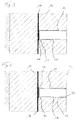
- the construction pit enclosure 10 has an annularly closed enclosure wall 12, of which only partially two slotted wall panels 14 according to FIG Fig. 1 are shown.
- the slot wall panels 14 have a substantially rectangular cross section. However, it may also be provided oval-shaped or circular cross-sections. Due to the process, the individual slot wall panels 14 are produced separately, with a vertical butt joint 16 forming between two adjacent slot wall panels 14.
- the vertical butt joint 16 extends from a bottom portion to the upper end of the respective adjacent slot wall panels 14.
- a joint tape 18 is placed in the creation of the slot wall panels 14, even before the Slot wall panels 14 are cured.
- the slot wall panels 14 are made in a conventional manner from a mortar or concrete and are optionally provided with a metal reinforcement.
- the construction pit enclosure 10 has a base plate 20.
- the bottom plate 20 is in the illustrated embodiment according to Fig. 2 also made of concrete and is connected via a projection 22 form-fitting manner with the enclosing wall 12.
- a horizontal butt joint 24 is formed, which forms in an annular manner along the enclosing wall 12 to the bottom plate 20.
- a receiving bore 15 is introduced before creating the bottom plate 22 in the enclosing wall 12 in the region of the vertical butt joint 16.
- a cylindrical sealing element 30 is inserted, through which the vertical butt joint 16 is sealed horizontally.
- Adjacent to the sealing element 30 is in the illustrated embodiment in the lower region of the bottom plate 20 along the horizontal butt joint 24, a horizontal seal 28, which is formed as an annular sealing band provided. The horizontal seal 28 prevents ingress of moisture or water along the annular horizontal butt joint 24 on the bottom plate 20.
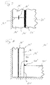
- a detail view of the seal according to the invention is shown, wherein in the receiving bore 15 in the slot wall panel 14, a sealing element 30 is inserted, which is designed as a hose sleeve 34.
- the hose sleeve 34 is completed on the one hand with a bottom.
- the receiving bore 15 is brought down to the joint tape 18.
- a sealing washer 36 may be provided from an elastic material. In principle, it is possible to introduce the sealing disc 36 before the creation of the receiving bore 15 with the joint tape 18 or in the created receiving bore 15.
- the hose sleeve 34 is provided with a fillable filling material, through which the flexible hose sleeve 34 is widened in its circumference and is pressed so tight against the wall of the receiving bore 15.
- FIG Fig. 4 An alternative embodiment of the sealing element 30 is shown in FIG Fig. 4 shown.
- the sealing element 30 is formed as a tubular metal sleeve 32 with a closed bottom portion. The bottom region adjoins the joint tape 18 in the slot wall panel 14 via a sealing washer 36.
- the metal sleeve 32 is inserted into the receiving bore 15 substantially by means of a press fit, wherein on the outer circumference a sealant, not shown, for sealing the gap between the wall of the receiving bore 15 and the metal sleeve 32 may be provided.
- the metal sleeve 32 is additionally anchored to the slot wall panel 14 at its end pointing to the inside of the enclosing wall 12 or to the interior of the excavation by means of an annular fastening element 33.
- the fastener 33 is formed as a flange-shaped retaining ring.
- the receiving bore 15 is initially introduced only to an intermediate portion 13 in the Umsch widelyungswand 12. Subsequently, a probing bore 19 with a small diameter, wherein the probing bore 19 is preferably carried out done by hand. Once the joint sealing tape 18 is reached, the probing hole 19 is terminated and the receiving bore 15 is performed up to the final depth according to the probing hole 19. Then, a sealing washer 36 for sealing any damage to the joint sealing strip 18 and then the sealing element 30, not shown, are used.
- FIG. 6 An alternative arrangement variant is in Fig. 6 shown.
- the receiving bore 15 is created by the joint sealing tape 18 through.
- the joint sealing strip 18 is pierced, so that the sealing element to be used takes over the function of the joint sealing strip 18 with.
- FIGS. 7 and 8 To illustrate the invention is in the FIGS. 7 and 8 a conventional excavation enclosure 10 'with a partially shown Umsch widelyungswand 12' of Schlitzwandpanelen 14 'and a bottom plate 20' shown.
- the vertical butt joints 16 'between adjacent Schlitzwandpanelen 14' are each sealed by a vertical joint sealing strip 18 ', so that no water from the bottom can penetrate into the pit laterally.
- a horizontal butt joint 24 'formed between the horizontal bottom plate 20' and the vertical enclosing wall 12 ' is sealed by means of a horizontal seal 28'.
- the enclosing wall 12 ' ends flush with the bottom plate 20'.
Abstract
Die Erfindung betrifft eine Baugrubenumschließung und ein Verfahren zum Erstellen einer Baugrubenumschließung, wobei im Boden eine im Wesentlichen vertikale Umschließungswand aus Schlitzwandpanelen erstellt wird, deren vertikale Stoßfugen mittels eines Fugendichtbandes abgedichtet sind, der Boden innerhalb der Umschließungswand ausgehoben wird, und eine im Wesentlichen horizontale Bodenplatte vorgesehen wird, welche an die Umschließungswand angrenzt. Gemäß der Erfindung ist vorgesehen, dass an mindestens einer vertikalen Stoßfuge zwischen zwei angrenzenden Schlitzwandpanelen in die Umschließungswand eine sich zum Fugendichtband erstreckende Aufnahmebohrung eingebracht wird und dass in die Aufnahmebohrung ein Dichtelement zum Bilden einer horizontalen Abdichtung eingebracht wird.The invention relates to a construction pit enclosure and a method of constructing a construction pit enclosure, wherein a substantially vertical enclosure wall of slotted wall panels is created in the ground, the vertical joints are sealed by a joint sealing strip, the soil is excavated within the enclosure wall, and provided a substantially horizontal bottom plate which adjoins the enclosure wall. According to the invention it is provided that at least one vertical butt joint between two adjacent Schlitzwandpanelen in the Umschließungswand a extending to the joint sealing tape receiving bore is introduced and that in the receiving bore a sealing element is introduced to form a horizontal seal.
Description
Die Erfindung betrifft ein Verfahren zum Erstellen einer Baugrubenumschließung, bei welchem im Boden eine im Wesentlichen vertikale Umschließungswand aus Schlitzwandpanelen erstellt wird, deren vertikale Stoßfugen mittels eines Fugendichtbandes abgedichtet sind, der Boden innerhalb der Umschließungswand ausgehoben wird, und eine im Wesentlichen horizontale Bodenplatte vorgesehen wird, welche an die Umschließungswand angrenzt, gemäß dem Oberbegriff des Anspruchs 1.The invention relates to a method for constructing a construction pit enclosure in which a substantially vertical enclosure wall of slotted wall panels is created in the ground, the vertical joints are sealed by means of a joint sealing strip, the floor is dug within the enclosure wall, and a substantially horizontal floor slab is provided, which adjoins the enclosing wall, according to the preamble of claim 1.
Die Erfindung betrifft weiterhin eine Baugrubenumschließung mit einer im Wesentlichen vertikalen Umschließungswand im Boden, welche aus Schlitzwandpanelen gebildet ist, deren vertikale Stoßfugen mittels eines Fugendichtbandes abgedichtet sind, und einer im Wesentlichen horizontalen Bodenplatte, welche an die Umschließungswand angrenzt und die Baugrube nach unten abdichtet, gemäß dem Oberbegriff des Anspruchs 10.The invention further relates to a construction pit enclosure having a substantially vertical enclosure wall in the bottom formed by slot wall panels whose vertical joints are sealed by a joint sealing strip and a substantially horizontal floor plate adjacent to the enclosure wall and sealing the excavation downwardly the preamble of
Weiterhin betrifft die Erfindung ein Dichtelement für ein derartiges Verfahren und eine derartige Baugrubenumschließung.Furthermore, the invention relates to a sealing element for such a method and such Baugrubenumschließ.
Aus der
In einem unteren Bereich ist eine Bodenplatte vorgesehen, welche die Baugrube gegen einen Grundwasserdurchtritt von unten abdichtet. Die Bodenplatte kann durch eine wassersperrende Bodenschicht gebildet oder als ein Bauwerkteil hergestellt sein. Zwischen den vertikalen Schlitzwandpanelen bilden sich Stoßfugen aus, die undichte Bereiche darstellen.In a lower area, a bottom plate is provided, which seals the pit against a groundwater passage from below. The bottom plate may be formed by a water-barrier bottom layer or made as a structural part. Between the vertical Schlitzwandpanelen form joints, which represent leaking areas.
In der
Eine ähnliche Anordnung mit zwei parallelen vertikalen Fugenbändern ist aus der
Entlang der horizontalen Stoßfuge, welche zwischen der Bodenplatte und der umgebenden Umschließungswand gebildet ist, kann eine horizontale Dichtung vorgesehen sein. So beschreibt die
Allerdings sind die Fugendichtbänder und Dichteinrichtungen oftmals nicht ausreichend, eine so erstellte Baugrubenumschließung gegen Wasserdurchtritt abzudichten.However, the joint sealing strips and sealing devices are often not sufficient to seal a construction pit enclosure thus created against water penetration.
Aus der
Weiterhin ist es bekannt, den unteren Bereich einer Baugrubenumschließung mit aufwändigen Dichtungsmaßnahmen zu versehen, um gezielt undichte Stellen zu beseitigen. Dies ist ebenfalls sehr zeit- und kostenaufwändig.Furthermore, it is known to provide the lower portion of a Baugrubenumschließ with elaborate sealing measures to selectively eliminate leaks. This is also very time consuming and costly.
Der Erfindung liegt die Aufgabe zugrunde, eine Baugrubenumschließung und ein Verfahren zum Erstellen einer Baugrubenumschließung anzugeben, mit welchen in effizienter Weise eine besonders dichte Baugrubenumschließung ermöglicht wird. Weiterhin ist es Aufgabe der Erfindung, ein Dichtelement hierfür anzugeben.The invention has for its object to provide a Baugrubenumschließ and a method for creating a Baugrubenumschließ, which is made possible in an efficient manner, a particularly dense Baugrubenumschließ. It is another object of the invention to provide a sealing element for this purpose.
Nach der Erfindung wird die Aufgabe zum einen durch ein Verfahren mit den Merkmalen des Anspruchs 1, eine Baugrubenumschließung mit den Merkmalen des Anspruchs 10 beziehungsweise durch ein Dichtelement mit den Merkmalen des Anspruchs 13 gelöst. Bevorzugte Ausführungsformen sind in den jeweils abhängigen Ansprüchen angegeben.According to the invention, the object is achieved on the one hand by a method having the features of claim 1, a construction pit enclosure having the features of
Das erfindungsgemäße Verfahren zum Erstellen einer Baugrubenumschließung ist dadurch gekennzeichnet, dass an mindestens einer vertikalen Stoßfuge zwischen zwei angrenzenden Schlitzwandpanelen in die Umschließungswand eine sich zum Fugendichtband erstreckende Aufnahmebohrung eingebracht wird und dass in die Aufnahmebohrung ein Dichtelement zum Bilden einer horizontalen Abdichtung eingebracht wird.The inventive method for creating a Baugrubenumschließ is characterized in that at least one vertical butt joint between two adjacent Schlitzwandpanelen in the Umschließungswand a extending to the joint sealing tape receiving bore is introduced and that in the receiving bore a sealing element is introduced to form a horizontal seal.
Die Erfindung beruht auf der Erkenntnis, dass beim Eintritt von Wasser in eine gattungsgemäß erstellte Baugrubenumschließung das Wasser maßgeblich entlang der vertikalen Stoßfugen in einem Bereich eindringt, welcher sich zwischen einem im Wesentlichen mittig angeordneten Fugenband zwischen den Schlitzwandpanelen und der Bodenplatte erstreckt. Dabei kann das Wasser aufgrund von Kapillarkräften vertikal in der Stoßfuge nach oben steigen und so an der Bodenplatte vorbei in die Baugrube eindringen. Um dies zu verhindern, wird an der vertikalen Stoßfuge zwischen zwei angrenzenden Schlitzwandpanelen in die Umschließungswand eine etwa horizontale Aufnahmebohrung eingebracht, welche sich zum Fugendichtband erstreckt. In dieser Aufnahmebohrung wird dann ein Dichtelement eingebracht, welches die Aufnahmebohrung und damit den kritischen Bereich der vertikalen Stoßfuge zwischen dem vertikalen Fugendichtband und der angrenzenden Bodenplatte abdichtet. Ein nach oben Steigen des Wassers entlang der vertikalen Stoßfuge wird damit unterbunden. Hierdurch wird eine sehr gute Abdichtung des unteren Bereiches der Baugrubenumschließung erzielt. Damit kann das Erstellen einer Innenwanne entfallen, so dass die Baugrubenumschließung unmittelbar als eine Innenwand des Bauwerkes dienen kann.The invention is based on the finding that when water enters a generously constructed excavation enclosure, the water substantially penetrates along the vertical joints in a region which extends between a substantially centrally located joint tape between the diaphragm wall panels and the floor slab. The water can rise due to capillary forces vertically in the butt joint upwards and thus penetrate past the bottom plate in the excavation. To prevent this, an approximately horizontal receiving bore is introduced at the vertical butt joint between two adjacent Schlitzwandpanelen in the Umschließungswand, which extends to the joint sealing tape. In this receiving bore, a sealing element is then introduced, which seals the receiving bore and thus the critical area of the vertical butt joint between the vertical joint sealing strip and the adjacent base plate. An upward rising of the water along the vertical butt joint will thus prevented. As a result, a very good seal of the lower portion of Baugrubenumschließ achieved. Thus, the creation of an inner tub omitted, so that the Baugrubenumschließ can serve directly as an inner wall of the building.
Eine bevorzugte Ausführungsform der Erfindung besteht darin, dass die mindestens eine Aufnahmebohrung auf Höhe der Bodenplatte in die Umschließungswand eingebracht wird. Die Aufnahmebohrung kann dabei vorzugsweise horizontal oder in einem schrägen Winkel erstellt werden. Dies ermöglicht eine möglichst kurze und damit effiziente Bohrung. Die Bodenplatte kann durch eine wassersperrende Bodenschicht, welche natürlich besteht oder durch Gelinjektionen abgedichtet wurde, oder als ein Bauwerkteil, etwa aus Beton, gebildet sein.A preferred embodiment of the invention is that the at least one receiving bore is introduced at the level of the bottom plate in the Umschließungswand. The receiving bore can preferably be created horizontally or at an oblique angle. This allows the shortest possible and thus efficient bore. The bottom plate may be formed by a water-barrier bottom layer, which is natural or sealed by gel injections, or as a structural part, such as concrete.
Grundsätzlich kann die Aufnahmebohrung unmittelbar über einer bestehenden Bodenplatte in die Umschließungswand eingebracht werden.In principle, the receiving bore can be introduced directly over an existing base plate in the Umschließungswand.
Besonders bevorzugt ist es nach einer Verfahrensvariante der Erfindung, dass die Bodenplatte erstellt wird und dass die mindestens eine Aufnahmebohrung vor dem Erstellen der Bodenplatte eingebracht wird. Die Aufnahmebohrung kann insbesondere auf dem Höhenniveau der Bodenplatte erstellt werden. Nach dem Abdichten kann dann eine Bodenplatte separat gefertigt werden, etwa durch Betonieren.According to a variant of the invention, it is particularly preferred that the bottom plate is created and that the at least one receiving bore is introduced before the bottom plate is produced. The receiving bore can be created in particular at the height level of the bottom plate. After sealing, a bottom plate can then be made separately, such as by concreting.
Gemäß einer Weiterbildung der Erfindung ist es bevorzugt, dass die Aufnahmebohrung von einer Innenseite der Umschließungswand bis zum vertikalen Fugendichtband oder darüber hinaus in die Umschließungswand eingebracht wird. Die Aufnahmebohrung verläuft aber horizontal oder in einem gewissen Schrägungswinkel, bis die Aufnahmebohrung nahe an das Fugendichtband heranreicht oder dieses vorzugsweise kontaktiert. Die Aufnahmebohrung erstreckt sich somit quer zur vertikalen Stoßfuge, so dass nach Einbringung des Dichtelementes ein kapillares Aufsteigen von Wasser zwischen dem vertikalen Fugendichtband und der Bodenplatte unterbunden ist. In bestimmten Fällen kann die Aufnahmebohrung über das Dichtband hinaus in die Umschließungswand eingebracht werden. Dabei wird das Fugendichtband beim Einbringen der Bohrung in diesem Bereich entfernt und die Dichtfunktion dann von dem eingebrachten Dichtelement übernommen. In Einzelfällen ist es auch möglich, die Aufnahmebohrung bis zur Außenseite der Umschließungswand durchzuführen, so dass das Dichtband sich quer durch die Umschließungswand erstreckt und die vertikale Stoßfuge zwischen den zwei angrenzenden Schlitzwandpanelen über die gesamte Panelbreite abgedichtet ist.According to one embodiment of the invention, it is preferred that the receiving bore is introduced from an inner side of the enclosing wall to the vertical joint sealing tape or beyond in the Umschließungswand. However, the receiving bore extends horizontally or at a certain angle of inclination until the receiving bore comes close to the joint sealing tape or this preferably contacted. The receiving bore thus extends transversely to the vertical butt joint, so that after introduction of the sealing element capillary rising of water between the vertical joint sealing strip and the bottom plate is prevented. In certain cases, the receiving bore can be introduced beyond the sealing strip into the enclosing wall. In this case, the joint sealing strip is removed during the introduction of the bore in this area and the sealing function is then taken over by the introduced sealing element. In some cases, it is also possible, the receiving bore to the outside of the enclosing wall so that the sealing band extends transversely through the enclosure wall and the vertical butt joint between the two adjacent slot wall panels is sealed over the entire panel width.
Abhängig von der Art und Weise der Erstellung der Bodenplatte ist es nicht zwingend erforderlich, dass im Eckbereich zwischen Bodenplatte und der Umschließungswand eine separate Dichtung vorgesehen ist. Für eine besonders zuverlässige Abdichtung ist es jedoch nach einer Ausführungsform der Erfindung vorteilhaft, dass die Bodenplatte an die Umschließungswand unter Ausbildung einer horizontalen Stoßfuge angrenzt, welche mit einer horizontalen Dichtung abgedichtet wird. Die horizontale Dichtung kann dabei eine ringförmige Dichteinrichtung, insbesondere ein über Eck geschlagenes Dichtband sein. Vorzugsweise erstreckt sich die horizontale Dichtung ringförmig entlang dem Rand der gesamten Bodenplatte.Depending on the manner in which the bottom plate is produced, it is not absolutely necessary for a separate seal to be provided in the corner region between the bottom plate and the enclosing wall. For a particularly reliable seal, however, it is advantageous according to an embodiment of the invention that the bottom plate adjoins the enclosing wall to form a horizontal butt joint, which is sealed with a horizontal seal. The horizontal seal may be an annular sealing device, in particular a sealing tape which has been folded over the corner. Preferably, the horizontal seal extends annularly along the edge of the entire bottom plate.
Grundsätzlich kann das vertikale Fugendichtband zwischen den einzelnen Schlitzwandpanelen auf jede geeignete Weise angeordnet werden. Auch können die Schlitzwandpanele, auch Dichtwandpanele genannt, auf eine beliebige Weise durch Erstellen und Auffüllen eines Loches im Boden gefertigt werden, etwa mittels Bohren. Die so erzeugte Schlitz- oder Dichtwand kann als Bohrpfahlwand bezeichnet werden. Eine bevorzugte Ausführungsform der Erfindung besteht darin, dass die Schlitzwandpanele schrittweise mittels eines Schlitzwandgreifers oder einer Schlitzwandfräse durch Erzeugen von Schlitzen im Boden erstellt werden, welche mit einer aushärtbaren Masse verfüllt werden, und dass vor dem Aushärten das vertikale Fugendichtband in den Schlitz eingesetzt wird. Das Einsetzen des vertikalen Fugendichtbandes kann insbesondere in bekannter Weise mit einem Abschalelement erfolgen, durch welches eine definierte Seitenfläche jedes Schlitzwandpanels vorgegeben wird. Das Abschalelement wird in bekannter Weise wieder aus dem Schlitz entfernt.In principle, the vertical joint sealing tape can be arranged between the individual slot wall panels in any suitable manner. Also, the slot wall panels, also called sealing wall panels, can be made in any way by creating and filling a hole in the ground, such as by drilling. The slot or sealing wall thus produced may be referred to as a bored pile wall. A preferred embodiment of the invention is that the trench wall panels are made progressively by means of a trench grab or wall trench by creating slots in the ground which are filled with a curable composition and prior to curing the vertical joint sealant tape is inserted into the slot. The insertion of the vertical joint sealing strip can in particular be effected in a known manner with a shuttering element, by means of which a defined side surface of each slot wall panel is predetermined. The Abschalelement is removed in a known manner again from the slot.
Weiterhin ist das erfindungsgemäße Verfahren in bevorzugter Weise dadurch weitergebildet, dass das Dichtelement einen zylindrischen Außenumfang aufweist, welches in die Aufnahmebohrung passend eingesetzt wird. Das Dichtelement weist dabei eine Länge auf, welche kleiner, gleich oder größer als die eingebrachte Aufnahmebohrung ist. Je nach Art der Ausbildung und des Materiales des Dichtelementes, welche aus einem starren oder flexiblen Material bestehen kann, wird das Dichtelement mit einer Presspassung oder Spielpassung in die Aufnahmebohrung eingesetzt.Furthermore, the method according to the invention is further developed in a preferred manner in that the sealing element has a cylindrical outer circumference, which is suitably inserted into the receiving bore. The sealing element has a length which is smaller than, equal to or greater than the introduced receiving bore. Depending on the type of training and the material of the sealing element, which may consist of a rigid or flexible material, the Inserted sealing element with a press fit or clearance in the receiving bore.
Gemäß einer Weiterentwicklung der Erfindung ist es bevorzugt, dass das Dichtelement eine feste Metallhülse aufweist, welche mit einer Verbindungsmasse und/oder einem Befestigungselement in der Aufnahmebohrung befestigt wird. Vorzugsweise ist das Dichtelement insgesamt als eine Metallhülse ausgebildet, wobei die Metallhülse ein Rohrkörper oder ein zumindest weitgehendes massives Stangenelement sein kann. Die Metallhülse wird dabei vorzugsweise mit einer definierten Spielpassung in die Aufnahmebohrung eingesetzt, wobei ein Freiraum zwischen der Bohrungswand und der Außenseite der Metallhülse gegeben ist. In diesen Freiraum kann ein Mörtel oder eine andere Verbindungs- und Dichtmasse eingespritzt werden, durch welche die Metallhülse in der Aufnahmebohrung fluiddicht verankert wird. Als Dicht- und Verankerungsmasse kann grundsätzlich jedes geeignete Material, insbesondere ein Mörtel, eingesetzt werden. Die Metallhülse kann sich dabei über die gesamte Länge der Aufnahmebohrung oder nur über einen Teilbereich erstrecken. Alternativ oder ergänzend kann die Metallhülse mit einem Befestigungselement, etwa einem Ringflansch, an der Umschließungswand verankert sein.According to a further development of the invention, it is preferred that the sealing element has a fixed metal sleeve which is fastened with a connecting mass and / or a fastening element in the receiving bore. Preferably, the sealing element is formed overall as a metal sleeve, wherein the metal sleeve may be a tubular body or an at least largely solid rod member. The metal sleeve is preferably used with a defined clearance in the receiving bore, with a clearance between the bore wall and the outside of the metal sleeve is given. In this space, a mortar or other compound and sealant can be injected, through which the metal sleeve is anchored fluid-tight in the receiving bore. In principle, any suitable material, in particular a mortar, can be used as the sealing and anchoring compound. The metal sleeve can extend over the entire length of the receiving bore or only over a partial area. Alternatively or additionally, the metal sleeve can be anchored to the enclosing wall with a fastening element, such as an annular flange.
Gemäß einer weiteren Ausführungsvariante der Erfindung ist es vorteilhaft, dass das Dichtelement eine flexible Schlauchhülse aufweist, welche mit Spiel in die Aufnahmebohrung eingesetzt wird, und dass die Schlauchhülse mit einer Füllmasse verfüllt wird, welche die Schlauchhülse erweitert und dabei fest und abdichtend in der Aufnahmebohrung verankert. In einem Grundzustand weist die Schlauchhülse eine Spielpassung zum Durchmesser der Aufnahmebohrung auf, so dass die Schlauchhülse einfach eingesetzt werden kann. Der Schlauch kann aus Gummi, einem Kunststoff oder einem Textilmaterial gebildet sein. Durch Einleiten einer Füllmasse, insbesondere einer aufquellbaren und aushärtbaren Füllmasse, wird der Außenumfang der Schlauchhülse erweitert und dicht gegen die Wand der Aufnahmebohrung gedrückt. Nach Aushärtung der Füllmasse wird so ein dicht in der Aufnahmebohrung anliegendes Dichtelement erzeugt. Die Schlauchhülse erstreckt sich vorzugsweise über die gesamte Länge der Aufnahmebohrung oder nur über einen Teilbereich. Insbesondere kann auch eine Kombination aus Schlauchhülse und Metallhülse vorgesehen sein, wobei ein oder mehrere Längenbereiche des Dichtelementes jeweils aus einer Schlauchhülse oder einer Metallhülse gebildet sind.According to a further embodiment of the invention, it is advantageous that the sealing element has a flexible hose sleeve which is inserted with play into the receiving bore, and that the hose sleeve is filled with a filling compound which expands the hose sleeve and anchored firmly and sealingly in the receiving bore , In a basic state, the hose sleeve has a clearance fit to the diameter of the receiving bore, so that the hose sleeve can be easily used. The hose may be formed of rubber, a plastic or a textile material. By introducing a filling compound, in particular a swellable and curable filling compound, the outer circumference of the hose sleeve is widened and pressed tightly against the wall of the receiving bore. After hardening of the filling compound, a sealing element fitting tightly in the receiving bore is produced. The hose sleeve preferably extends over the entire length of the receiving bore or only over a partial area. In particular, a combination of hose sleeve and metal sleeve may be provided be, wherein one or more length ranges of the sealing element are each formed from a hose sleeve or a metal sleeve.
Die Erfindung umfasst weiterhin eine Baugrubenumschließung, welche insbesondere nach dem zuvor beschriebenen Verfahren hergestellt ist. Die erfindungsgemäße Baugrubenumschließung ist dadurch gekennzeichnet, dass an mindestens einer vertikalen Stoßfuge zwischen zwei angrenzenden Schlitzwandpanelen in die Umschließungswand eine sich zum Fugendichtband erstreckende Aufnahmebohrung ausgebildet ist, und dass in die Aufnahmebohrung ein Dichtelement zum Bilden einer horizontalen Abdichtung eingebracht ist. Hierdurch wird eine Baugrubenumschließung erreicht, bei der eine besonders gute Abdichtung gegen Flüssigkeitseintritt durch die vertikale Stoßfuge gegeben ist.The invention further comprises a construction pit enclosure, which in particular is produced according to the method described above. The construction pit enclosure according to the invention is characterized in that at at least one vertical butt joint between two adjacent Schlitzwandpanelen in the Umschließungswand a extending to the joint sealing tape receiving bore is formed, and that in the receiving bore a sealing element is introduced for forming a horizontal seal. As a result, a Baugrubenumschließ is achieved in which a particularly good seal against liquid entry is given by the vertical butt joint.
Eine bevorzugte Weiterbildung der erfindungsgemäßen Baugrubenumschließung besteht darin, dass an jeder vertikalen Stoßfuge eine Aufnahmebohrung mit Dichtelement angeordnet ist. Durch die Dichtelemente wird so verhindert, dass insbesondere Grundwasser entlang den vertikalen Stoßfugen an der Bodenplatte vorbei durch die Kapillarkräfte nach oben steigt und so in die Baugrube gelangen kann.A preferred development of the construction pit enclosure according to the invention is that a receiving bore with sealing element is arranged on each vertical butt joint. By sealing elements is thus prevented in particular groundwater along the vertical joints on the bottom plate over by the capillary forces rises and so can get into the pit.
Eine besonders zuverlässige Abdichtung wird nach einer Weiterbildung der Erfindung dadurch erreicht, dass sich das Dichtelement von einer Innenseite der Umschließungswand mindestens bis zu dem Fugendichtband entlang der vertikalen Stoßfuge erstreckt. Durch das Dichtelement, welches horizontal oder mit einem gewissen Schrägungswinkel zur Horizontalen angeordnet ist, wird so eine zuverlässige Sperrung der vertikalen Stoßfuge gegenüber aufsteigendem Wasser erzielt.A particularly reliable sealing is achieved according to a development of the invention in that the sealing element extends from an inner side of the enclosing wall at least as far as the joint sealing strip along the vertical butt joint. By the sealing element, which is arranged horizontally or with a certain helix angle to the horizontal, so a reliable blocking of the vertical butt joint against rising water is achieved.
Weiterhin umfasst die Erfindung ein Dichtelement für ein Verfahren oder eine Baugrubenumschließung, welche zuvor beschrieben wurden. Dieses ist nach der Erfindung dadurch gekennzeichnet, dass das Dichtelement zylindrisch und passend zu einer Aufnahmebohrung in einer Umschließungswand einer Baugrubenumschließung ausgebildet ist. Mit dem erfindungsgemäßen Dichtelement können die zuvor beschriebenen Vorteile bei einer Baugrubenumschließung und ein Verfahren zum Erstellen einer Baugrubenumschließung erzielt werden.Furthermore, the invention comprises a sealing element for a method or a construction pit enclosure, which have been described above. This is according to the invention characterized in that the sealing element is cylindrical and adapted to a receiving bore in a Umschließungswand a Baugrubenumschließ. With the sealing element according to the invention, the advantages described above can be achieved in a construction pit enclosure and a method for creating a construction pit enclosure.
Eine bevorzugte Ausführungsform besteht nach der Erfindung darin, dass das Dichtelement eine feste Metallhülse aufweist. Die Metallhülse ist passend, insbesondere mit einer Spielpassung, zum Durchmesser der Aufnahmebohrung ausgebildet. Die feste Metallhülse wird mittels einer Dichtmasse fest und abdichtend in der Aufnahmebohrung verankert.A preferred embodiment according to the invention is that the sealing element has a solid metal sleeve. The metal sleeve is suitable, in particular formed with a clearance fit to the diameter of the receiving bore. The solid metal sleeve is firmly and sealingly anchored in the receiving bore by means of a sealant.
Alternativ oder ergänzend kann es nach einer Weiterbildung der Erfindung vorgesehen sein, dass das Dichtelement eine flexible Schlauchhülse aufweist, welche vorzugsweise mit einer aufquellbaren Füllmasse verfüllt ist. Durch ein Aufquellen der Füllmasse wird die elastische Schlauchhülse, welche insbesondere ein Gummi- oder Kunststoffschlauch sein kann, definiert im Durchmesser erweitert, so dass der Außenumfang der Schlauchhülse sich dicht und wassersperrend an die Wand der Aufnahmebohrung anlegt. Die aufquellbare Füllmasse kann aushärten, so dass eine zuverlässige und stabile Verankerung des Dichtelementes in der Umschließungswand erfolgt.Alternatively or additionally, it may be provided according to a development of the invention that the sealing element has a flexible hose sleeve, which is preferably filled with a swellable filling compound. By swelling the filling compound, the elastic hose sleeve, which may be a rubber or plastic hose in particular, defined in diameter widens, so that the outer circumference of the hose sleeve tight and water-tight against the wall of the receiving bore. The swellable filling compound can harden, so that a reliable and stable anchoring of the sealing element takes place in the enclosing wall.
Die Erfindung wird nachfolgend anhand von bevorzugten Ausführungsbeispielen weiter erläutert, welche schematisch in den Zeichnungen dargestellt sind. In den Zeichnungen zeigen:
- Fig. 1
- eine Querschnittsansicht von oben auf einen Ausschnitt einer Umschließungswand mit Stoßfuge;
- Fig. 2
- eine Querschnittsansicht durch den Schnitt A-A von
Fig. 1 mit dem Eckbereich zur angrenzenden Bodenplatte; - Fig. 3
- eine schematische Querschnittsansicht durch eine Umschließungswand mit einem eingesetzten schlauchförmigen Dichtelement;
- Fig. 4
- eine Querschnittsansicht entsprechend
Fig. 3 mit einem eingesetzten hülsenförmigen Dichtelement; - Fig. 5
- eine Querschnittsansicht durch eine Umschließungswand mit einer eingebrachten ersten Aufnahmebohrung;
- Fig. 6
- eine Querschnittsansicht durch eine Umschließungswand mit einer eingebrachten zweiten Aufnahmebohrung;
- Fig. 7
- eine Teilansicht zu einer Baugrubenumschließung von oben gemäß dem Stand der Technik; und
- Fig. 8
- eine Teilquerschnittsansicht von der Seite zu dem Ausschnitt einer Baugrubenumschließung gemäß
Fig. 7
- Fig. 1
- a cross-sectional view from above of a portion of a Umschließungswand with butt joint;
- Fig. 2
- a cross-sectional view through the section AA of
Fig. 1 with the corner area to the adjacent floor panel; - Fig. 3
- a schematic cross-sectional view through a Umschließungswand with an inserted tubular sealing element;
- Fig. 4
- a cross-sectional view accordingly
Fig. 3 with an inserted sleeve-shaped sealing element; - Fig. 5
- a cross-sectional view through a Umschließungswand with an introduced first receiving bore;
- Fig. 6
- a cross-sectional view through a Umschließungswand with an introduced second receiving bore;
- Fig. 7
- a partial view of a construction pit enclosure from above according to the prior art; and
- Fig. 8
- a partial cross-sectional view from the side to the section of a construction pit enclosure according to
Fig. 7
Gemäß den
In einem unteren Bereich der Umschließungswand 12 weist die Baugrubenumschließung 10 eine Bodenplatte 20 auf. Die Bodenplatte 20 ist in dem dargestellten Ausführungsbeispiel gemäß
Zum Unterbinden des Eindringens von Feuchtigkeit und des Einsickerns von Wasser entlang der vertikalen Stoßfuge 16 zwischen dem Fugenband 18 und der Bodenplatte 22 wird vor dem Erstellen der Bodenplatte 22 in die Umschließungswand 12 im Bereich der vertikalen Stoßfuge 16 eine Aufnahmebohrung 15 eingebracht. In die Aufnahmebohrung 15 wird ein zylindrisches Dichtelement 30 eingesetzt, durch welches die vertikale Stoßfuge 16 horizontal abgedichtet wird. Angrenzend an das Dichtelement 30 ist bei dem dargestellten Ausführungsbeispiel im unteren Bereich der Bodenplatte 20 entlang der horizontalen Stoßfuge 24 eine horizontale Dichtung 28, welche als ein ringförmiges Dichtband ausgebildet ist, vorgesehen. Die horizontale Dichtung 28 verhindert ein Eindringen von Feuchtigkeit oder Wasser entlang der ringförmigen horizontalen Stoßfuge 24 an der Bodenplatte 20.To prevent the ingress of moisture and the infiltration of water along the vertical joint 16 between the
In
Eine alternative Ausgestaltung des Dichtelementes 30 ist in
Eine Möglichkeit des Einbringens der Aufnahmebohrung 15 unter besonderer Schonung des Fugendichtbandes 18 ist im Zusammenhang mit
Eine alternative Anordnungsvariante ist in
Zur Verdeutlichung der Erfindung ist in die
Nach einer Erkenntnis der Erfindung kann trotz dieser bekannten Dichtmaßnahmen in nicht unerheblicher Weise Feuchtigkeit und Wasser entlang den vertikalen Stoßfugen 16' über einen Bereich zwischen dem Fugendichtband 18' und der Bodenplatte 20' von unten in die Baugrube eindringen, wie schematisch durch den Pfeil P1 angedeutet ist. Das Wasser kann dabei aufgrund von Kapillarkräften entlang der vertikalen Stoßfuge 16 nach oben steigen. Dieses Eindringen von Wasser wird durch die erfindungsgemäße Lösung verhindert.According to a finding of the invention, despite these known sealing measures moisture and water can penetrate along the vertical joints 16 'over an area between the joint sealing tape 18' and the bottom plate 20 'from below into the excavation, as indicated schematically by the arrow P1 is. The water can rise due to capillary forces along the vertical butt joint 16 upwards. This ingress of water is prevented by the solution according to the invention.
Claims (15)
dadurch gekennzeichnet,
dass die mindestens eine Aufnahmebohrung (15) auf Höhe der Bodenplatte (20) in die Umschließungswand (12) eingebracht wird.Method according to claim 1,
characterized,
the at least one receiving bore (15) is introduced at the level of the bottom plate (20) in the containment wall (12).
dadurch gekennzeichnet,
dass die Bodenplatte (20) erstellt wird und
dass die mindestens eine Aufnahmebohrung (15) vor dem Erstellen der Bodenplatte (20) eingebracht wird.Method according to claim 1 or 2,
characterized,
that the bottom plate (20) is created and
the at least one receiving bore (15) is introduced prior to creating the base plate (20).
dadurch gekennzeichnet,
dass die Aufnahmebohrung (15) von einer Innenseite der Umschließungswand (12) bis zum vertikalen Fugendichtband (18) oder darüber hinaus in die Umschließungswand (12) eingebracht wird.Method according to one of claims 1 to 3,
characterized,
in that the receiving bore (15) is introduced from an inner side of the enclosing wall (12) to the vertical joint sealing strip (18) or beyond into the enclosing wall (12).
dadurch gekennzeichnet,
dass die Bodenplatte (20) an die Umschließungswand (12) unter Ausbildung einer horizontalen Stoßfuge (24) angrenzt, welche mit einer horizontalen Dichtung (28) abgedichtet wird.Method according to one of claims 1 to 4,
characterized,
in that the bottom plate (20) adjoins the enclosing wall (12) to form a horizontal butt joint (24) which is sealed with a horizontal seal (28).
dadurch gekennzeichnet,
dass die Schlitzwandpanele (14) schrittweise mittels eines Schlitzwandgreifers oder einer Schlitzwandfräse durch Erzeugen von Schlitzen im Boden erstellt werden, welche mit einer aushärtbaren Masse verfüllt werden, und
dass vor dem Aushärten das vertikale Fugendichtband 15 in den Schlitz eingesetzt wird.Method according to one of claims 1 to 5,
characterized,
that the slotted wall panels (14) are made stepwise by means of a trench wall grab or a trench wall cutter by creating slots in the ground which are filled with a hardenable mass, and
that the vertical joint sealing band is inserted into the slot 15 prior to curing.
dadurch gekennzeichnet,
dass das Dichtelement (30) einen zylindrischen Außenumfang aufweist, welches in die Aufnahmebohrung (15) passend eingesetzt wird.Method according to one of claims 1 to 6,
characterized,
in that the sealing element (30) has a cylindrical outer circumference, which is suitably inserted into the receiving bore (15).
dadurch gekennzeichnet,
dass das Dichtelement (30) eine feste Metallhülse (32) aufweist, welche mit einer Verbindungsmasse und/oder einem Befestigungselement (33) in der Aufnahmebohrung (15) befestigt wird.Method according to one of claims 1 to 7,
characterized,
in that the sealing element (30) has a fixed metal sleeve (32) which is fastened with a connecting mass and / or a fastening element (33) in the receiving bore (15).
dadurch gekennzeichnet,
dass das Dichtelement (30) eine flexible Schlauchhülse (34) aufweist, welche mit Spiel in die Aufnahmebohrung (15) eingesetzt wird, und
dass die Schlauchhülse (34) mit einer Füllmasse verfüllt wird, welche die Schlauchhülse (34) erweitert und dabei fest und abdichtend in der Aufnahmebohrung (15) verankert.Method according to one of claims 1 to 8,
characterized,
in that the sealing element (30) has a flexible hose sleeve (34) which is inserted into the receiving bore (15) with play, and
in that the hose sleeve (34) is filled with a filling compound which expands the hose sleeve (34) and anchors it firmly and sealingly in the receiving bore (15).
dadurch gekennzeichnet,
dass an jeder vertikalen Stoßfuge (16) eine Aufnahmebohrung (15) mit Dichtelement (30) angeordnet ist.Construction pit enclosure according to claim 10,
characterized,
in that a receiving bore (15) with sealing element (30) is arranged on each vertical butt joint (16).
dadurch gekennzeichnet,
dass sich das Dichtelement (30) von einer Innenseite der Umschließungswand (12) mindestens bis zu dem Fugendichtband (18) entlang der vertikalen Stoßfuge (16) erstreckt.Construction pit enclosure according to claim 10 or 11,
characterized,
in that the sealing element (30) extends from an inner side of the enclosing wall (12) at least as far as the joint sealing strip (18) along the vertical butt joint (16).
dadurch gekennzeichnet,
characterized,
dadurch gekennzeichnet,
dass das Dichtelement (30) eine feste Metallhülse (32) aufweist.Sealing element according to claim 13,
characterized,
in that the sealing element (30) has a fixed metal sleeve (32).
dadurch gekennzeichnet,
dass das Dichtelement (30) eine flexible Schlauchhülse (34) aufweist, welche mit einer aufquellbaren Füllmasse verfüllt ist.Sealing element according to claim 13 or 14,
characterized,
that the sealing element (30) comprises a flexible hose sleeve (34) which is filled with a filling material swellable.
Priority Applications (2)
| Application Number | Priority Date | Filing Date | Title |
|---|---|---|---|
| EP16153356.7A EP3199708B1 (en) | 2016-01-29 | 2016-01-29 | Excavation enclosure and method for creating an excavation enclosure |
| PCT/EP2016/081441 WO2017129319A1 (en) | 2016-01-29 | 2016-12-16 | Foundation surrounding means and method for creating a foundation surrounding means |
Applications Claiming Priority (1)
| Application Number | Priority Date | Filing Date | Title |
|---|---|---|---|
| EP16153356.7A EP3199708B1 (en) | 2016-01-29 | 2016-01-29 | Excavation enclosure and method for creating an excavation enclosure |
Publications (2)
| Publication Number | Publication Date |
|---|---|
| EP3199708A1 true EP3199708A1 (en) | 2017-08-02 |
| EP3199708B1 EP3199708B1 (en) | 2018-12-19 |
Family
ID=55274989
Family Applications (1)
| Application Number | Title | Priority Date | Filing Date |
|---|---|---|---|
| EP16153356.7A Active EP3199708B1 (en) | 2016-01-29 | 2016-01-29 | Excavation enclosure and method for creating an excavation enclosure |
Country Status (2)
| Country | Link |
|---|---|
| EP (1) | EP3199708B1 (en) |
| WO (1) | WO2017129319A1 (en) |
Cited By (1)
| Publication number | Priority date | Publication date | Assignee | Title |
|---|---|---|---|---|
| CN111172990A (en) * | 2019-11-11 | 2020-05-19 | 浙江省建筑设计研究院 | Vertical connection structure of sleeve-type prefabricated underground continuous wall of pre-buried front and back row reinforcing bar |
Citations (6)
| Publication number | Priority date | Publication date | Assignee | Title |
|---|---|---|---|---|
| NL1008925C1 (en) * | 1998-03-13 | 1999-09-14 | Alex Blokker Duik En Bergingsb | Building floor by pouring concrete into foundation pit enclosed by dam walls |
| US6164873A (en) | 1997-09-12 | 2000-12-26 | Finic B.V. | Double-wing deformable stop-end pipe for forming the joining surfaces of concrete-cast wall elements |
| DE10334730A1 (en) | 2003-07-30 | 2005-02-24 | Ed. Züblin Ag | Construction of water-proof inner shell and ceiling edges of building constructed in under-cover method with cover being without contact to excavation walls in areas where vertical wall sections contact each other |
| DE102005052162A1 (en) | 2004-11-12 | 2006-05-18 | Ed. Züblin Ag | Thermal insulated slotted walls for fluids has thermal insulation which is part of precast concrete parts or part of prefabricated finished parts made from reinforcing cage and thermal insulation |
| EP2549021B1 (en) | 2011-07-18 | 2013-09-11 | Bauer Spezialtiefbau GmbH | Pump storage power plant and method for its production |
| EP2647765A1 (en) | 2012-04-03 | 2013-10-09 | Bauer Spezialtiefbau GmbH | Shuttering element for a diaphragm wall and method for producing a diaphragm wall |
-
2016
- 2016-01-29 EP EP16153356.7A patent/EP3199708B1/en active Active
- 2016-12-16 WO PCT/EP2016/081441 patent/WO2017129319A1/en active Application Filing
Patent Citations (6)
| Publication number | Priority date | Publication date | Assignee | Title |
|---|---|---|---|---|
| US6164873A (en) | 1997-09-12 | 2000-12-26 | Finic B.V. | Double-wing deformable stop-end pipe for forming the joining surfaces of concrete-cast wall elements |
| NL1008925C1 (en) * | 1998-03-13 | 1999-09-14 | Alex Blokker Duik En Bergingsb | Building floor by pouring concrete into foundation pit enclosed by dam walls |
| DE10334730A1 (en) | 2003-07-30 | 2005-02-24 | Ed. Züblin Ag | Construction of water-proof inner shell and ceiling edges of building constructed in under-cover method with cover being without contact to excavation walls in areas where vertical wall sections contact each other |
| DE102005052162A1 (en) | 2004-11-12 | 2006-05-18 | Ed. Züblin Ag | Thermal insulated slotted walls for fluids has thermal insulation which is part of precast concrete parts or part of prefabricated finished parts made from reinforcing cage and thermal insulation |
| EP2549021B1 (en) | 2011-07-18 | 2013-09-11 | Bauer Spezialtiefbau GmbH | Pump storage power plant and method for its production |
| EP2647765A1 (en) | 2012-04-03 | 2013-10-09 | Bauer Spezialtiefbau GmbH | Shuttering element for a diaphragm wall and method for producing a diaphragm wall |
Cited By (2)
| Publication number | Priority date | Publication date | Assignee | Title |
|---|---|---|---|---|
| CN111172990A (en) * | 2019-11-11 | 2020-05-19 | 浙江省建筑设计研究院 | Vertical connection structure of sleeve-type prefabricated underground continuous wall of pre-buried front and back row reinforcing bar |
| CN111172990B (en) * | 2019-11-11 | 2021-09-10 | 浙江省建筑设计研究院 | Vertical connection structure of sleeve-type prefabricated underground continuous wall of pre-buried front and back row reinforcing bar |
Also Published As
| Publication number | Publication date |
|---|---|
| EP3199708B1 (en) | 2018-12-19 |
| WO2017129319A1 (en) | 2017-08-03 |
Similar Documents
| Publication | Publication Date | Title |
|---|---|---|
| DE1759338C3 (en) | Method for producing a grout anchor and device for carrying out the method | |
| DE2651023C2 (en) | Method for producing an in-situ concrete pile with a foot extension and device for carrying out the method | |
| EP0642620B1 (en) | Process, tubular spreader and device for erecting concrete walls by means of braced shutterings | |
| DE102007055878A1 (en) | sealing | |
| DE102008014700A1 (en) | Corrosion-protected self-drilling anchor and method for its production | |
| DE3535320A1 (en) | METHOD AND DEVICE FOR SETTING A ROD, WIRE OR TUBULAR INSTALLATION COMPONENT IN A FLOOR INFORMATION WITH PRESSING WATER | |
| DE3445965A1 (en) | COMPACTING DEPTH, METHOD AND DEVICE FOR PRODUCING THE SAME | |
| CH696445A5 (en) | Concrete element for covering a tunnel. | |
| DE2226169C2 (en) | Device for the formation of a grouting anchor | |
| DE4422648C2 (en) | Sollriß joint rail | |
| CH600077A5 (en) | Seal for gaps in concrete structures | |
| EP3199708B1 (en) | Excavation enclosure and method for creating an excavation enclosure | |
| DE102008018382A1 (en) | Method for securing retaining walls | |
| DE2722978A1 (en) | Seal for piling section fixings - is liq. sealant injected over mesh between adjacent locking edges and plate to set hard | |
| EP1922449A1 (en) | Method and device for consolidating soils and stabilizing foundations | |
| DE3322198C2 (en) | ||
| DE2354764A1 (en) | Process for passing anchor tube through a wall - uses temporary sealing sleeve with frusto-conical lip on the end | |
| DE3838880C1 (en) | Method of producing a grouted anchor, and grouted anchor for carrying out the method | |
| DE3634906A1 (en) | Precast concrete member and method of constructing a trench wall with the use of the precast concrete member | |
| DE10104376C1 (en) | Process for sealing a building joint and joint tape therefor | |
| EP0405520B1 (en) | Method of making shafts | |
| DE4217711A1 (en) | Sealing strip with lengthwise ribs between concrete components - has integral mounting for injection hose or expanding seal | |
| DE2617758C3 (en) | Process for injecting plastic fillings into walls, walls, facade walls and the like, as well as injection tubes for carrying out the process | |
| DE3404074A1 (en) | Method of making a concrete trench wall | |
| DE6609772U (en) | COMPONENT FOR THE PRODUCTION OF SLOTTED OR DRILLED PILE WALLS. |
Legal Events
| Date | Code | Title | Description |
|---|---|---|---|
| PUAI | Public reference made under article 153(3) epc to a published international application that has entered the european phase |
Free format text: ORIGINAL CODE: 0009012 |
|
| STAA | Information on the status of an ep patent application or granted ep patent |
Free format text: STATUS: THE APPLICATION HAS BEEN PUBLISHED |
|
| AK | Designated contracting states |
Kind code of ref document: A1 Designated state(s): AL AT BE BG CH CY CZ DE DK EE ES FI FR GB GR HR HU IE IS IT LI LT LU LV MC MK MT NL NO PL PT RO RS SE SI SK SM TR |
|
| AX | Request for extension of the european patent |
Extension state: BA ME |
|
| STAA | Information on the status of an ep patent application or granted ep patent |
Free format text: STATUS: REQUEST FOR EXAMINATION WAS MADE |
|
| 17P | Request for examination filed |
Effective date: 20180124 |
|
| RBV | Designated contracting states (corrected) |
Designated state(s): AL AT BE BG CH CY CZ DE DK EE ES FI FR GB GR HR HU IE IS IT LI LT LU LV MC MK MT NL NO PL PT RO RS SE SI SK SM TR |
|
| GRAP | Despatch of communication of intention to grant a patent |
Free format text: ORIGINAL CODE: EPIDOSNIGR1 |
|
| STAA | Information on the status of an ep patent application or granted ep patent |
Free format text: STATUS: GRANT OF PATENT IS INTENDED |
|
| INTG | Intention to grant announced |
Effective date: 20180622 |
|
| RIN1 | Information on inventor provided before grant (corrected) |
Inventor name: IDDA, KLAUS, DR. Inventor name: ACKERMANN, ANDREAS Inventor name: LORENZ, CHRISTIAN |
|
| GRAS | Grant fee paid |
Free format text: ORIGINAL CODE: EPIDOSNIGR3 |
|
| GRAJ | Information related to disapproval of communication of intention to grant by the applicant or resumption of examination proceedings by the epo deleted |
Free format text: ORIGINAL CODE: EPIDOSDIGR1 |
|
| GRAL | Information related to payment of fee for publishing/printing deleted |
Free format text: ORIGINAL CODE: EPIDOSDIGR3 |
|
| STAA | Information on the status of an ep patent application or granted ep patent |
Free format text: STATUS: REQUEST FOR EXAMINATION WAS MADE |
|
| GRAR | Information related to intention to grant a patent recorded |
Free format text: ORIGINAL CODE: EPIDOSNIGR71 |
|
| STAA | Information on the status of an ep patent application or granted ep patent |
Free format text: STATUS: GRANT OF PATENT IS INTENDED |
|
| INTC | Intention to grant announced (deleted) | ||
| GRAA | (expected) grant |
Free format text: ORIGINAL CODE: 0009210 |
|
| STAA | Information on the status of an ep patent application or granted ep patent |
Free format text: STATUS: THE PATENT HAS BEEN GRANTED |
|
| INTG | Intention to grant announced |
Effective date: 20181107 |
|
| AK | Designated contracting states |
Kind code of ref document: B1 Designated state(s): AL AT BE BG CH CY CZ DE DK EE ES FI FR GB GR HR HU IE IS IT LI LT LU LV MC MK MT NL NO PL PT RO RS SE SI SK SM TR |
|
| REG | Reference to a national code |
Ref country code: GB Ref legal event code: FG4D Free format text: NOT ENGLISH |
|
| REG | Reference to a national code |
Ref country code: CH Ref legal event code: EP |
|
| REG | Reference to a national code |
Ref country code: IE Ref legal event code: FG4D Free format text: LANGUAGE OF EP DOCUMENT: GERMAN |
|
| REG | Reference to a national code |
Ref country code: DE Ref legal event code: R096 Ref document number: 502016002872 Country of ref document: DE |
|
| REG | Reference to a national code |
Ref country code: AT Ref legal event code: REF Ref document number: 1078862 Country of ref document: AT Kind code of ref document: T Effective date: 20190115 |
|
| REG | Reference to a national code |
Ref country code: NL Ref legal event code: MP Effective date: 20181219 |
|
| PG25 | Lapsed in a contracting state [announced via postgrant information from national office to epo] |
Ref country code: LV Free format text: LAPSE BECAUSE OF FAILURE TO SUBMIT A TRANSLATION OF THE DESCRIPTION OR TO PAY THE FEE WITHIN THE PRESCRIBED TIME-LIMIT Effective date: 20181219 Ref country code: HR Free format text: LAPSE BECAUSE OF FAILURE TO SUBMIT A TRANSLATION OF THE DESCRIPTION OR TO PAY THE FEE WITHIN THE PRESCRIBED TIME-LIMIT Effective date: 20181219 Ref country code: LT Free format text: LAPSE BECAUSE OF FAILURE TO SUBMIT A TRANSLATION OF THE DESCRIPTION OR TO PAY THE FEE WITHIN THE PRESCRIBED TIME-LIMIT Effective date: 20181219 Ref country code: BG Free format text: LAPSE BECAUSE OF FAILURE TO SUBMIT A TRANSLATION OF THE DESCRIPTION OR TO PAY THE FEE WITHIN THE PRESCRIBED TIME-LIMIT Effective date: 20190319 Ref country code: FI Free format text: LAPSE BECAUSE OF FAILURE TO SUBMIT A TRANSLATION OF THE DESCRIPTION OR TO PAY THE FEE WITHIN THE PRESCRIBED TIME-LIMIT Effective date: 20181219 Ref country code: NO Free format text: LAPSE BECAUSE OF FAILURE TO SUBMIT A TRANSLATION OF THE DESCRIPTION OR TO PAY THE FEE WITHIN THE PRESCRIBED TIME-LIMIT Effective date: 20190319 |
|
| REG | Reference to a national code |
Ref country code: LT Ref legal event code: MG4D |
|
| PG25 | Lapsed in a contracting state [announced via postgrant information from national office to epo] |
Ref country code: RS Free format text: LAPSE BECAUSE OF FAILURE TO SUBMIT A TRANSLATION OF THE DESCRIPTION OR TO PAY THE FEE WITHIN THE PRESCRIBED TIME-LIMIT Effective date: 20181219 Ref country code: SE Free format text: LAPSE BECAUSE OF FAILURE TO SUBMIT A TRANSLATION OF THE DESCRIPTION OR TO PAY THE FEE WITHIN THE PRESCRIBED TIME-LIMIT Effective date: 20181219 Ref country code: GR Free format text: LAPSE BECAUSE OF FAILURE TO SUBMIT A TRANSLATION OF THE DESCRIPTION OR TO PAY THE FEE WITHIN THE PRESCRIBED TIME-LIMIT Effective date: 20190320 Ref country code: AL Free format text: LAPSE BECAUSE OF FAILURE TO SUBMIT A TRANSLATION OF THE DESCRIPTION OR TO PAY THE FEE WITHIN THE PRESCRIBED TIME-LIMIT Effective date: 20181219 |
|
| PG25 | Lapsed in a contracting state [announced via postgrant information from national office to epo] |
Ref country code: NL Free format text: LAPSE BECAUSE OF FAILURE TO SUBMIT A TRANSLATION OF THE DESCRIPTION OR TO PAY THE FEE WITHIN THE PRESCRIBED TIME-LIMIT Effective date: 20181219 |
|
| PG25 | Lapsed in a contracting state [announced via postgrant information from national office to epo] |
Ref country code: ES Free format text: LAPSE BECAUSE OF FAILURE TO SUBMIT A TRANSLATION OF THE DESCRIPTION OR TO PAY THE FEE WITHIN THE PRESCRIBED TIME-LIMIT Effective date: 20181219 Ref country code: PT Free format text: LAPSE BECAUSE OF FAILURE TO SUBMIT A TRANSLATION OF THE DESCRIPTION OR TO PAY THE FEE WITHIN THE PRESCRIBED TIME-LIMIT Effective date: 20190419 Ref country code: IT Free format text: LAPSE BECAUSE OF FAILURE TO SUBMIT A TRANSLATION OF THE DESCRIPTION OR TO PAY THE FEE WITHIN THE PRESCRIBED TIME-LIMIT Effective date: 20181219 Ref country code: CZ Free format text: LAPSE BECAUSE OF FAILURE TO SUBMIT A TRANSLATION OF THE DESCRIPTION OR TO PAY THE FEE WITHIN THE PRESCRIBED TIME-LIMIT Effective date: 20181219 Ref country code: PL Free format text: LAPSE BECAUSE OF FAILURE TO SUBMIT A TRANSLATION OF THE DESCRIPTION OR TO PAY THE FEE WITHIN THE PRESCRIBED TIME-LIMIT Effective date: 20181219 |
|
| PG25 | Lapsed in a contracting state [announced via postgrant information from national office to epo] |
Ref country code: RO Free format text: LAPSE BECAUSE OF FAILURE TO SUBMIT A TRANSLATION OF THE DESCRIPTION OR TO PAY THE FEE WITHIN THE PRESCRIBED TIME-LIMIT Effective date: 20181219 Ref country code: SK Free format text: LAPSE BECAUSE OF FAILURE TO SUBMIT A TRANSLATION OF THE DESCRIPTION OR TO PAY THE FEE WITHIN THE PRESCRIBED TIME-LIMIT Effective date: 20181219 Ref country code: IS Free format text: LAPSE BECAUSE OF FAILURE TO SUBMIT A TRANSLATION OF THE DESCRIPTION OR TO PAY THE FEE WITHIN THE PRESCRIBED TIME-LIMIT Effective date: 20190419 Ref country code: SM Free format text: LAPSE BECAUSE OF FAILURE TO SUBMIT A TRANSLATION OF THE DESCRIPTION OR TO PAY THE FEE WITHIN THE PRESCRIBED TIME-LIMIT Effective date: 20181219 Ref country code: EE Free format text: LAPSE BECAUSE OF FAILURE TO SUBMIT A TRANSLATION OF THE DESCRIPTION OR TO PAY THE FEE WITHIN THE PRESCRIBED TIME-LIMIT Effective date: 20181219 |
|
| REG | Reference to a national code |
Ref country code: CH Ref legal event code: PL |
|
| REG | Reference to a national code |
Ref country code: DE Ref legal event code: R097 Ref document number: 502016002872 Country of ref document: DE |
|
| PG25 | Lapsed in a contracting state [announced via postgrant information from national office to epo] |
Ref country code: LU Free format text: LAPSE BECAUSE OF NON-PAYMENT OF DUE FEES Effective date: 20190129 |
|
| REG | Reference to a national code |
Ref country code: BE Ref legal event code: MM Effective date: 20190131 |
|
| PLBE | No opposition filed within time limit |
Free format text: ORIGINAL CODE: 0009261 |
|
| STAA | Information on the status of an ep patent application or granted ep patent |
Free format text: STATUS: NO OPPOSITION FILED WITHIN TIME LIMIT |
|
| REG | Reference to a national code |
Ref country code: IE Ref legal event code: MM4A |
|
| PG25 | Lapsed in a contracting state [announced via postgrant information from national office to epo] |
Ref country code: DK Free format text: LAPSE BECAUSE OF FAILURE TO SUBMIT A TRANSLATION OF THE DESCRIPTION OR TO PAY THE FEE WITHIN THE PRESCRIBED TIME-LIMIT Effective date: 20181219 Ref country code: MC Free format text: LAPSE BECAUSE OF FAILURE TO SUBMIT A TRANSLATION OF THE DESCRIPTION OR TO PAY THE FEE WITHIN THE PRESCRIBED TIME-LIMIT Effective date: 20181219 |
|
| 26N | No opposition filed |
Effective date: 20190920 |
|
| PG25 | Lapsed in a contracting state [announced via postgrant information from national office to epo] |
Ref country code: BE Free format text: LAPSE BECAUSE OF NON-PAYMENT OF DUE FEES Effective date: 20190131 |
|
| PG25 | Lapsed in a contracting state [announced via postgrant information from national office to epo] |
Ref country code: CH Free format text: LAPSE BECAUSE OF NON-PAYMENT OF DUE FEES Effective date: 20190131 Ref country code: LI Free format text: LAPSE BECAUSE OF NON-PAYMENT OF DUE FEES Effective date: 20190131 |
|
| PG25 | Lapsed in a contracting state [announced via postgrant information from national office to epo] |
Ref country code: IE Free format text: LAPSE BECAUSE OF NON-PAYMENT OF DUE FEES Effective date: 20190129 |
|
| PG25 | Lapsed in a contracting state [announced via postgrant information from national office to epo] |
Ref country code: SI Free format text: LAPSE BECAUSE OF FAILURE TO SUBMIT A TRANSLATION OF THE DESCRIPTION OR TO PAY THE FEE WITHIN THE PRESCRIBED TIME-LIMIT Effective date: 20181219 Ref country code: FR Free format text: LAPSE BECAUSE OF NON-PAYMENT OF DUE FEES Effective date: 20190219 |
|
| PG25 | Lapsed in a contracting state [announced via postgrant information from national office to epo] |
Ref country code: TR Free format text: LAPSE BECAUSE OF FAILURE TO SUBMIT A TRANSLATION OF THE DESCRIPTION OR TO PAY THE FEE WITHIN THE PRESCRIBED TIME-LIMIT Effective date: 20181219 |
|
| PG25 | Lapsed in a contracting state [announced via postgrant information from national office to epo] |
Ref country code: MT Free format text: LAPSE BECAUSE OF FAILURE TO SUBMIT A TRANSLATION OF THE DESCRIPTION OR TO PAY THE FEE WITHIN THE PRESCRIBED TIME-LIMIT Effective date: 20181219 |
|
| GBPC | Gb: european patent ceased through non-payment of renewal fee |
Effective date: 20200129 |
|
| PG25 | Lapsed in a contracting state [announced via postgrant information from national office to epo] |
Ref country code: GB Free format text: LAPSE BECAUSE OF NON-PAYMENT OF DUE FEES Effective date: 20200129 |
|
| PG25 | Lapsed in a contracting state [announced via postgrant information from national office to epo] |
Ref country code: CY Free format text: LAPSE BECAUSE OF FAILURE TO SUBMIT A TRANSLATION OF THE DESCRIPTION OR TO PAY THE FEE WITHIN THE PRESCRIBED TIME-LIMIT Effective date: 20181219 |
|
| PG25 | Lapsed in a contracting state [announced via postgrant information from national office to epo] |
Ref country code: HU Free format text: LAPSE BECAUSE OF FAILURE TO SUBMIT A TRANSLATION OF THE DESCRIPTION OR TO PAY THE FEE WITHIN THE PRESCRIBED TIME-LIMIT; INVALID AB INITIO Effective date: 20160129 |
|
| REG | Reference to a national code |
Ref country code: AT Ref legal event code: MM01 Ref document number: 1078862 Country of ref document: AT Kind code of ref document: T Effective date: 20210129 |
|
| PG25 | Lapsed in a contracting state [announced via postgrant information from national office to epo] |
Ref country code: AT Free format text: LAPSE BECAUSE OF NON-PAYMENT OF DUE FEES Effective date: 20210129 |
|
| PG25 | Lapsed in a contracting state [announced via postgrant information from national office to epo] |
Ref country code: MK Free format text: LAPSE BECAUSE OF FAILURE TO SUBMIT A TRANSLATION OF THE DESCRIPTION OR TO PAY THE FEE WITHIN THE PRESCRIBED TIME-LIMIT Effective date: 20181219 |
|
| PGFP | Annual fee paid to national office [announced via postgrant information from national office to epo] |
Ref country code: DE Payment date: 20230120 Year of fee payment: 8 |