EP3199441A2 - Mehrgängigesgetriebe - Google Patents
Mehrgängigesgetriebe Download PDFInfo
- Publication number
- EP3199441A2 EP3199441A2 EP17154971.0A EP17154971A EP3199441A2 EP 3199441 A2 EP3199441 A2 EP 3199441A2 EP 17154971 A EP17154971 A EP 17154971A EP 3199441 A2 EP3199441 A2 EP 3199441A2
- Authority
- EP
- European Patent Office
- Prior art keywords
- gear
- epicyclical
- shift
- section
- unit
- Prior art date
- Legal status (The legal status is an assumption and is not a legal conclusion. Google has not performed a legal analysis and makes no representation as to the accuracy of the status listed.)
- Pending
Links
Images


Classifications
-
- F—MECHANICAL ENGINEERING; LIGHTING; HEATING; WEAPONS; BLASTING
- F16—ENGINEERING ELEMENTS AND UNITS; GENERAL MEASURES FOR PRODUCING AND MAINTAINING EFFECTIVE FUNCTIONING OF MACHINES OR INSTALLATIONS; THERMAL INSULATION IN GENERAL
- F16H—GEARING
- F16H3/00—Toothed gearings for conveying rotary motion with variable gear ratio or for reversing rotary motion
- F16H3/44—Toothed gearings for conveying rotary motion with variable gear ratio or for reversing rotary motion using gears having orbital motion
- F16H3/78—Special adaptation of synchronisation mechanisms to these gearings
-
- B—PERFORMING OPERATIONS; TRANSPORTING
- B62—LAND VEHICLES FOR TRAVELLING OTHERWISE THAN ON RAILS
- B62M—RIDER PROPULSION OF WHEELED VEHICLES OR SLEDGES; POWERED PROPULSION OF SLEDGES OR SINGLE-TRACK CYCLES; TRANSMISSIONS SPECIALLY ADAPTED FOR SUCH VEHICLES
- B62M11/00—Transmissions characterised by the use of interengaging toothed wheels or frictionally-engaging wheels
- B62M11/04—Transmissions characterised by the use of interengaging toothed wheels or frictionally-engaging wheels of changeable ratio
- B62M11/14—Transmissions characterised by the use of interengaging toothed wheels or frictionally-engaging wheels of changeable ratio with planetary gears
- B62M11/16—Transmissions characterised by the use of interengaging toothed wheels or frictionally-engaging wheels of changeable ratio with planetary gears built in, or adjacent to, the ground-wheel hub
-
- B—PERFORMING OPERATIONS; TRANSPORTING
- B62—LAND VEHICLES FOR TRAVELLING OTHERWISE THAN ON RAILS
- B62M—RIDER PROPULSION OF WHEELED VEHICLES OR SLEDGES; POWERED PROPULSION OF SLEDGES OR SINGLE-TRACK CYCLES; TRANSMISSIONS SPECIALLY ADAPTED FOR SUCH VEHICLES
- B62M11/00—Transmissions characterised by the use of interengaging toothed wheels or frictionally-engaging wheels
- B62M11/04—Transmissions characterised by the use of interengaging toothed wheels or frictionally-engaging wheels of changeable ratio
- B62M11/14—Transmissions characterised by the use of interengaging toothed wheels or frictionally-engaging wheels of changeable ratio with planetary gears
- B62M11/18—Transmissions characterised by the use of interengaging toothed wheels or frictionally-engaging wheels of changeable ratio with planetary gears with a plurality of planetary gear units
-
- F—MECHANICAL ENGINEERING; LIGHTING; HEATING; WEAPONS; BLASTING
- F16—ENGINEERING ELEMENTS AND UNITS; GENERAL MEASURES FOR PRODUCING AND MAINTAINING EFFECTIVE FUNCTIONING OF MACHINES OR INSTALLATIONS; THERMAL INSULATION IN GENERAL
- F16H—GEARING
- F16H3/00—Toothed gearings for conveying rotary motion with variable gear ratio or for reversing rotary motion
- F16H3/44—Toothed gearings for conveying rotary motion with variable gear ratio or for reversing rotary motion using gears having orbital motion
- F16H3/62—Gearings having three or more central gears
- F16H3/66—Gearings having three or more central gears composed of a number of gear trains without drive passing from one train to another
-
- F—MECHANICAL ENGINEERING; LIGHTING; HEATING; WEAPONS; BLASTING
- F16—ENGINEERING ELEMENTS AND UNITS; GENERAL MEASURES FOR PRODUCING AND MAINTAINING EFFECTIVE FUNCTIONING OF MACHINES OR INSTALLATIONS; THERMAL INSULATION IN GENERAL
- F16H—GEARING
- F16H2200/00—Transmissions for multiple ratios
- F16H2200/003—Transmissions for multiple ratios characterised by the number of forward speeds
- F16H2200/0043—Transmissions for multiple ratios characterised by the number of forward speeds the gear ratios comprising four forward speeds
-
- F—MECHANICAL ENGINEERING; LIGHTING; HEATING; WEAPONS; BLASTING
- F16—ENGINEERING ELEMENTS AND UNITS; GENERAL MEASURES FOR PRODUCING AND MAINTAINING EFFECTIVE FUNCTIONING OF MACHINES OR INSTALLATIONS; THERMAL INSULATION IN GENERAL
- F16H—GEARING
- F16H2200/00—Transmissions for multiple ratios
- F16H2200/003—Transmissions for multiple ratios characterised by the number of forward speeds
- F16H2200/0056—Transmissions for multiple ratios characterised by the number of forward speeds the gear ratios comprising seven forward speeds
-
- F—MECHANICAL ENGINEERING; LIGHTING; HEATING; WEAPONS; BLASTING
- F16—ENGINEERING ELEMENTS AND UNITS; GENERAL MEASURES FOR PRODUCING AND MAINTAINING EFFECTIVE FUNCTIONING OF MACHINES OR INSTALLATIONS; THERMAL INSULATION IN GENERAL
- F16H—GEARING
- F16H2200/00—Transmissions for multiple ratios
- F16H2200/20—Transmissions using gears with orbital motion
- F16H2200/2002—Transmissions using gears with orbital motion characterised by the number of sets of orbital gears
- F16H2200/201—Transmissions using gears with orbital motion characterised by the number of sets of orbital gears with three sets of orbital gears
-
- F—MECHANICAL ENGINEERING; LIGHTING; HEATING; WEAPONS; BLASTING
- F16—ENGINEERING ELEMENTS AND UNITS; GENERAL MEASURES FOR PRODUCING AND MAINTAINING EFFECTIVE FUNCTIONING OF MACHINES OR INSTALLATIONS; THERMAL INSULATION IN GENERAL
- F16H—GEARING
- F16H2200/00—Transmissions for multiple ratios
- F16H2200/20—Transmissions using gears with orbital motion
- F16H2200/203—Transmissions using gears with orbital motion characterised by the engaging friction means not of the freewheel type, e.g. friction clutches or brakes
- F16H2200/2053—Transmissions using gears with orbital motion characterised by the engaging friction means not of the freewheel type, e.g. friction clutches or brakes with nine engaging means
-
- F—MECHANICAL ENGINEERING; LIGHTING; HEATING; WEAPONS; BLASTING
- F16—ENGINEERING ELEMENTS AND UNITS; GENERAL MEASURES FOR PRODUCING AND MAINTAINING EFFECTIVE FUNCTIONING OF MACHINES OR INSTALLATIONS; THERMAL INSULATION IN GENERAL
- F16H—GEARING
- F16H2200/00—Transmissions for multiple ratios
- F16H2200/20—Transmissions using gears with orbital motion
- F16H2200/2097—Transmissions using gears with orbital motion comprising an orbital gear set member permanently connected to the housing, e.g. a sun wheel permanently connected to the housing
Definitions
- the present invention relates to epicyclical multispeed internally geared hubs for bicycles, tricycles and other wholly or partially pedally or otherwise manually propelled vehicles.
- the advance of the sport of mountain biking has brought with it a need for gear units with a broad selection of different speeds for use in particularly mountainous terrain, sufficiently robust for use in rough terrain, and with features enabling high performance in competitive application.
- a problem herein lies in that internally geared hubs of today are not in these regards considered attractive.
- Such hubs are limited by their insufficient robustness, number of speeds, gear width, lateral rigidity, number of gear ratio alternatives, ease of operation, and their complexity and manufacturing costs.
- the present invention provides a hub gear that overcomes these issues.
- Rigidity in the rear frame of the pedally propelled vehicle is imperative for performance-oriented use in rough terrain.
- the rear wheel on a mountain bike used in rough terrain is exposed to higher and more sudden lateral forces than a road or urban bike used on pavement.
- the lateral forces are transferred as torsion forces to the rear frame by the wheel hub. If the hub bolt is too flexible or insufficiently pre tensioned, the frame wheel attachment flanges will be allowed to have slight separation from the hub ends during high lateral load.
- the frame itself will in this case be the major provider of system stiffness, and the system will be considered insufficiently rigid.
- Means for vertical shear force load carrying of the weight of the vehicle and rider are according to prior art provided in two basic variants.
- the hub comprises an axle defining an axis of rotation
- the first variant comprising hub-integrated or separable hub stubs or taps in both axial ends of the hub, of the same dimensions as the indentations standard on such frames, carrying the vertical shear forces, however not securing the hub to the frame.
- the hub is secured to the frame by powerful nuts, providing adequate rigidity for active riding in rough terrain. Removal of the wheel however, for example in case of a puncture, a tire change, maintenance, or for other reasons, is with such nuts complicated and time-consuming, requiring special tools, force, and in some instances, the competence of a specialist.
- a quick release system comprising a non load-bearing ⁇ 5mm through-bolt, with a nut in one end and a cup operated by a quick release lever in the other, the lever operated from an open longitudinal position in an arc towards a 90 degree angle relative to the through-bolt, the cup contracting along the through-bolt towards the nut, and when the bolt is pierced through the load bearing shaft of the hub, the hub taps mounted correctly in the frame's hub mounts, and in this manner operated, the quick release system clamps the frame against the hub, and by this pre load overcomes the separation forces thus securing the hub to the frame, keeping the wheel and frame connected.
- Patent DE202010012075 describes a hub featuring internal gear mechanisms as well as a shear force load carrying through-bolt. Said hub is provided with means for bolt-on frame mounting requiring special tools and potentially the skill of a specialist for operation, although the use of a quick release solution with the hub is conceivable.
- the gear mechanisms are of a hybrid solution, comprising both an epicyclical unit and a standard rear derailleur gear system.
- the epicyclical unit offers only three different speeds, while inclusion of a derailleur system means the system compromises on robustness, reliability, and maintenance-requirements.
- the combination of a derailleur system with internal gear mechanisms enables only the elimination of the front derailleur, rather than the disposal of the whole flawed multispeed derailleur gear system.
- a high performance multispeed internally geared hub with attractive overall characteristics is described in DE19720796A1 , comprising a primary and a secondary epicyclical gear unit, the primary unit comprising four series of two mirrored sections with stepped planets, two ring gears, four sun gears, a primary shift mechanism with pawls selectively locking each sun and clutches selectively locking each set of planets to direct drive, the secondary gear unit featuring an epicyclical range gear with stepped planets providing direct drive or a full range reduction, operated by axially operated dog clutches.
- a particularly relevant feature of said epicyclical structure is its large number of alternative gear ratios and total gear ratio width, on gearfeatures making it the only realized internally geared substitute to the weak and primitive derailleur gear solution. Only few other epicyclical gear hubs with gear features achieving near this have been realized, most notable being said unit, DE4342347 and EP2008927 . Shifting is achieved by mechanisms generally known such as a rotatable shift axle with a non-rotatable surrounding hub shaft supporting the epicyclical mechanisms, the pawls hinged on the outer axle, the rotatable shift axle having detents which operate the pawls, thus locking or releasing elements in the epicyclical structure.
- All axially operated dog clutches are similarly shifted by the rotatable shift axle, which has circumferential tracks with an axial deviation, a rod being placed through an axial slot in the non-rotatable surrounding shaft such that when the shift axle is rotated, the rod is moved axially, thus operating dog clutches axially. If only one slot and rod is used per axial dog clutch, the ring will not operate evenly along its circumference, and rather be drawn or pulled by the rod from the circumferential region at where it abuts the ring. This may cause imprecise operation, ghost-shifting, and uneven wear.
- each rod requires also an axial slot on the rotatable shift axle for operation, and there are limitations as to how many such slots can be used if the axle is to rotate more than 360 degrees.
- the sun gear which is non-rotatably connected to the internal shaft is realized by the traditional means of the shaft and sun gear being separately manufactured, after which the sun gear is permanently and non-rotatably mounted to the shaft, in effect causing the two to operate as a single unit throughout the lifespan of the product. Manufacturing these two items separately and joining them in this manner contributes in making it challenging to realize said epicyclical unit in combination with a shear force load carrying through-bolt. Furthermore, the mechanisms of this realized body take up as much space axially as a traditional three-speed hub, yet do not offer a sufficient number of speeds to be considered a substitute to derailleur gears on gear ratio alternatives.
- An objective of the present invention is to provide an enclosed speed change gear unit, with key features enabling the unit to be considered attractive for active use in rough terrain. It should at least offer a large number of alternative speeds and a broad overall gear width, a compact and light weight design, a rigid interface to the vehicle, and user friendly means for hub to frame de/attachment.
- a further objective is to provide a speed change gear unit having an shaft defining an axis of rotation, a hub shell rotatably mounted on the shaft, the shaft being securable to frames with at least one frame stay, a transmission changeable among several speeds between the shell and shaft, one drive gear in drive connection with an input element of the transmission, one output element of the transmission in connection with the shell, and a rotatable shift sleeve for changing between speeds.
- a relatively wide gear width and options for at least four different ratios in between is desirable, preferably a minimum of seven speeds in total.
- the multispeed internally geared hub would in a preferred embodiment be provided with a massive, vertical shear force load carrying, quick release through-bolt, which without exposing the inner gear mechanisms of the hub is slidable into a hollow tunnel the whole axial length of the hub gear, as well as securable to the frame.
- the use of such through-bolt requires redesign of the epicyclical mechanisms and moving of the centrally located shift mechanisms radially towards the hub shell, which unless mitigated by a favourable redesign of the structure, causes an increase in hub casing size and overall weight. While definite measures of the minimum diameter sufficient for high performance are not available, it is widely considered that the ⁇ 5mm through-bolts which are typically used today for non load bearing quick release bolts are insufficiently rigid to be applied as shear force load carrying.
- a still further objective of the present invention is to provide an epicyclical multispeed internally geared hub comprising a hub shaft non-rotatably mounted to the vehicle frame, a driver, an epicyclical gear system according to the principles described in DE19745419A1 , with at least a first and a second epicyclical gear section, a sun gear joined non-rotatably to the hub shaft, a ring gear at least partially surrounding the epicyclical gearing system, a hub shell rotatably mounted to the hub shaft and downstream of the epicyclical gear mechanism, a shift mechanism connecting the driver to the gear system and the gear system to the driven unit, the gear shift control device enabling operation and selection of a desired gear ratio between the driver and the hub shell and consisting of an actuator, a carrier, and the particular locking mechanisms selected.
- Either of the first or second epicyclical gear section can be of a simple or stepped configuration, as this is known in the art, see e.g. DE102004011052A1 .
- the application of other epicyclical structures are also conceivable, such as the traditional one of several stepped planets mounted in series, offering 8-14 speeds, operated by traditional pawls or axial dog clutches.
- a redesign may be needed, encompassing integration of elements of the epicyclical gear system, such as sun wheels with the load bearing shaft of the epicyclical system, wherein the shaft and the sun gear is manufactured in one piece.
- the outer edges of the sun gear teeth may in certain such embodiments have to be not larger than the diameter of the shaft.
- the shaft could be reduced to allow for shift mechanisms on both axial sides of the machined sun gear and for lower weight.
- the above described multispeed gear structure may be provided with a range gear.
- the range gear does not necessarily have to offer a repetition of the full range of the primary unit, nor does the epicyclical structure have to make use of all available speeds of the primary unit.
- Each planet may be simple or staged, singe planets being preferred for axial and radial space considerations as well as ease of assembly.
- a simple planet range gear would have at least one planet meshed with the ring and sun gear in a straight radial line, while a stepped unit might have a sun gear meshed with a planet, non-rotatably connected to a different size planet, which meshes with a ring gear.
- shift mechanisms and means for selective connection of gear elements are conceivable for application to said structure. Operation may be achieved by means of circumferential rotation of a shift axle, axial sliding of rods or other motions appropriate, and for locking the epicyclical elements generally known shift mechanisms such as radially operated pawls and axial dog clutches may be provided.
- shift mechanisms such as radially operated pawls and axial dog clutches
- the use of radially working pawls for locking one or more sun gears to the shaft limits the number of locking positions per revolution of the sun gears, normally to less than 10 different positions per revolution.
- the gear unit may have a higher number of locking positions per revolution. Achieving more than 24 positions per revolution with such lock mechanisms is simple and preferable for the intended active use in rough terrain. Hence, such axial dog clutches mechanisms are preferred.
- a preferred embodiment employs also a rotatable shift axle within the tunnel of a hollow main epicyclical shaft, such shaft being considered as non shear force load carrying against the bicycle frame while at the same time epicyclically load bearing, as the gear mechanisms are attached to or supported by said shaft while said shaft not bearing the weight of the rider and vehicle against the wheel.
- the rotatable shift axle is provided with cams of differing levels partially or wholly surrounding the shaft circumferentially, each cam pushing a circular ball or an otherwise free, non-hinged member radially through openings in the main epicyclical shaft, operating shift rings axially or radially.
- each cam should have at least two different levels, enabling each cam and shift mechanism to operate and selectively lock or release more than one pair of shift rings.
- Said new shift mechanisms are capable of operating traditional epicyclical structures with two or more alternative gear ratios. For example, in a preferred embodiment it may be applied to the range gear, selectively engaging one pair of dog clutches axially, providing there shifting between only two different gear ratios.
- the shift cams are provided with several shift levels radially and that one such shift mechanism is applied to shift more than one pair of shift rings, one axially disposed shift mechanism thus providing more than two different gear ratios.
- these elements may be displaced radially, although such elements may also be axially displaced.
- a hub with 14 or a greater number of speeds may be realized, operated by merely three, in many manners advantageous, shift mechanisms.
- the shift mechanisms are simple and small yet comprise relatively large and easy to handle components, thus are easy to manufacture and assemble, robust and reliable, and when combined with said primary structure and range gear, enables an epicyclical multispeed internally geared hub for the type of use envisaged which is also particularly suitable for mass manufacturing and mass penetration of the market.
- Other shift configurations than these preferred are conceivable, for example hinged pawls or rod operated axial dog clutches, which are well known in the art.
- the invention is not limited to use within the hub of a wheel, and could for example be used as an intermediate shaft mechanism and arranged for this purpose at a location between the bottom bracket bearing and the hub of one of the two wheels of a bicycle at the behest of the bicycle designer, in which case the gear mechanisms could be connected via appropriate gear wheels, chains or the like on the driven side with the bottom bracket bearing, and on the driving side with a wheel, or within the bottom bracket bearing if such is found appropriate.
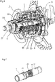
- Figure 1 shows a preferred embodiment of the multispeed epicyclical speed change gear hub, comprising a hub shell 1 with spoke mounts 2, for spokes (not shown) of a wheel, rotatably mounted on a hollow load bearing internal shaft 7.
- a torque arm 14 Non-rotatably mounted to one end of the internal shaft 7 is a torque arm 14 that transfers torque from the internal shaft 7 to the bicycle frame 10.
- a clamp ring or bolts 5 are used for attachment of a brake disc 6 to the hub shell 1.
- a left end piece 9 is non-rotatably mounted to the internal shaft 7.
- a right end piece 12 is non-rotatably mounted to the internal shaft 7.
- a load bearing, quick release through-bolt 15 is slided through the load bearing internal shaft 7.
- the multispeed epicyclical speed change gear hub also comprises a primary epicyclical unit 18, an intermediate shaft 21, and a secondary epicyclical unit 23, wherein the primary epicyclical unit 18 is selectively connectable with a rotatable inbound axle 19 through the inbound speed change mechanism 20 and selectably connectable through the outbound speed change mechanism 22 to the intermediate shaft 21, and the intermediate shaft 21 is selectively connectable with a secondary epicyclical unit 23 by means of a speed change mechanism 65, transferring outgoing torque to the hub shell 1 through the outbound element 66 of the secondary epicyclical unit 23.
- the reaction-torque of the primary epicyclical unit 18 and the secondary epicyclical unit 23 is transferred to the internal shaft 7.
- the quick release through-bolt 15 is slided through the internal tunnel of a shift axle 25, which in turn extends through the internal shaft 7.
- the through-bolt 15 quick release system buckles the frame 10 against the hub, and by this pre-tension overcomes the separation forces that might arise between the frame and parts, thus securing the frame to the hub, keeping the wheel and frame 10 rigidly connected.
- Inbound torque is transferred from the bicycle's chain (not shown), turning a cog 32, which is non-rotatably connected to the rotatable inbound axle 19, transferring torque to the inbound speed change mechanism 20.
- the inbound speed change mechanism 20 transfers torque to either of an inner 33, a middle 34, or an outer 35 rotating element of the primary epicyclical units 18. Said elements 33, 34 and 35 are always rotating with the same ratio of rotational speed relative to each other, where the inner element 33 rotates with the lowest speed, and the outer element 35 with the highest speed.
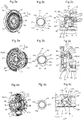
- first and preferred one is shown schematically in figure 5a . It consists of three epicyclical gear sections; a first epicyclical gear section 82, which has a sun wheel 84, a planet carrier 85, a ring gear 86 and planet gears 103, a second epicyclical gear section 83, which has a sun wheel 87, a planet carrier 88, a ring gear 89 and planet gears 104, and a third epicyclical gear section 23, which has a sun wheel 98, a planet carrier 100, a ring gear 101 and planet gears 99.
- the gear sections 82, 83, and 23 are coupled as follows; the sun wheel 84 of the first epicyclical gear section 82 is non-rotatably connected to the planet carrier 88 of the second epicyclical gear section 83, the ring gear 89 of the second epicyclical gear section 83 non-rotatably connected to the planet carrier 85 of the first epicyclical gear section 82, the ring gear 86 of the first epicyclical gear section 82 surrounding the second epicyclical gear section 83, and the sun gear 87 of the second epicyclical gear section 83 non-rotatably connected to the axle 7.
- Alternative speed gear ratios are enabled by selectively connecting the driving unit 19 to the sun wheel 84 of the first epicyclical gear section 82, the epicyclical holder 85 of the first epicyclical gear section 82 or the ring wheel 86 of the first epicyclical gear section 82, and selectively connecting the ring gear 89 of the second epicyclical gear section 83, the ring gear 86 of the first epicyclical gear section 82 or the epicyclical holder 88 of the second epicyclical gear section 83, to the driven unit 21.
- the third epicyclical gear section 23 is coupled to the second epicyclical gear section 83 through the intermediate shaft 21, which is connected to the sun wheel 98 of the third epicyclical section 23, which meshes with at least one simple planet gear 99 of the third epicyclical section 23, which mesh with the ring gear 101 of the third epicyclical section 23, which is connected with the load bearing internal shaft 7 through an automatic freewheel coupling 72.
- the sun wheel 98 of the third epicyclical section 23 and intermediate shaft 21 are selectively connectable to the ring gear 101 of the third epicyclical section 23, locking the section to direct drive.
- the planet carrier 100 of the third epicyclical section 23 connects to the hub shell 1 through the outbound element 66 of the third epicyclical section 23.
- a second embodiment is shown schematically in figure 5b and also consists of three epicyclical gear sections; a first epicyclical gear section 90, which has a sun wheel 92, a planet carrier 96, a ring gear 97 and planet gears 111, a second epicyclical gear section 91, which has a sun wheel 95, a planet carrier 96, a ring gear 97 and planet gears 112.
- the gear sections 90, 91 are coupled as follows; the sun gear 95 of the first epicyclical gear section 90 is non-rotatably connected to the axle 7, the ring gear 97 of the second epicyclical gear section 91 surrounding the first epicyclical gear section 90, the planet carrier 96 of the second epicyclical gear section 91 non-rotatably connected to the ring gear 94 of the first epicyclical gear section 90, and the planet carrier 93 of the first epicyclical gear section 90 non-rotatably connected to the sun wheel 95 of the second epicyclical gear section 91.
- Alternative speed gear ratios are enabled by selectively connecting the driving unit 19 to the ring gear 97 of the second epicyclical gear section 91, the ring gear 94 of the first epicyclical gear section 90 or the epicyclical holder 93 of the first epicyclical gear section 90, and selectively connecting the sun wheel 95 of the second epicyclical gear section 91, the epicyclical holder 96 of the second epicyclical gear section 91 or the ring wheel 97 of the second epicyclical gear section 91 to the driven unit 21.
- the third epicyclical gear section 23 is in this embodiment identical to the third epicyclical gear section 23 of the embodiment of figure 5 .
- a third embodiment is shown schematically in figure 5c , and consists of four epicyclical gear sections; a first epicyclical gear section 82 or 90, has a sun wheel 84 or 92, a planet carrier 85 or 96, a ring gear 86 or 97 and planet gears 103 or 111, a second epicyclical gear section 83 or 91, which has a sun wheel 87 or 95, a planet carrier 88 or 96, a ring gear 89 or 97 and planet gears 104 or 112, a third 113 and fourth epicyclical gear section 114 with a third sun wheel 105 coupled to the second epicyclical gear section 83 or 91 through the intermediate shaft 21, the sun wheel 105 of the third epicyclical section 113, meshing with at least one planet gear 106 of the third epicyclical section 113, the planet gears 106 of the third epicyclical section 113 non-rotatably connected with the planet gears 108 of the fourth epicyclical section 114, meshing with the ring gear 109
- the sun wheel 105 of the third epicyclical section 113 and the intermediate shaft 21 are selectively connectable to the ring gear 109 of the fourth epicyclical section 114, locking the third 113 and fourth 114 epicyclical sections to direct drive.
- the planet carrier 100 of the third 113 and fourth 114 epicyclical sections connect to the hub shell 1 through the outbound element 66 of the third epicyclical section 113.
- Alternative input and output elements of the third and fourth epicyclical sections are conceivable where this is known in the art.
- the sun wheel 87 is machined from the material of the shaft 7.
- Holes 73, 74, 75 through which shift balls 37, 51, 71 (shown in figures 1 , 2c, 3c and 4c ) operate shift rings 38, 39; 52, 53; 69, 70 (shown in figures 1 , 2c, 3c and 4c ) are not axial slots, rather relatively round if not circular penetrations of the shaft 7.
- the shift balls 37, 51, 71 can move axially and radially yet not tangentially to the shaft 7. This will be explained in detail below.
- the shift mechanisms consist of an inbound speed change mechanism 20, an outbound speed change mechanism 22 and a secondary epicyclical control mechanism 65.
- the inbound change mechanism 20 has three members 40, 41, 44 which selectively transfer the rotation of the driving unit 19 to one of the following elements of the first epicyclical gear section 82: the sun wheel 84, the planet carrier 85 or the ring gear 86.
- the outbound change mechanism 22 has three members 54, 55, 58, which selectively transfer the rotation of either the sun wheel 84 of the first epicyclical gear section 82 or the ring gear 89 or the planet carrier 88 of the second epicyclical gear section 83 to the sun wheel of the third epicyclical gear section 23.
- FIG. 8a shows the shift mechanism in a closed, locked position
- figure 8b shows the shift mechanism in open, free position
- Two wedge rings 200, 201 can either be free to move axially, or one of them can act as a reference and be axially fixed to a shaft 202, while the other will separate shift rings 203, 204.
- the two shift rings 203, 204 can either be of two way locking, dog type or freewheeling, one way locking.
- the angle or profile of the wedge surfaces 200a, 201a of the wedge rings 200, 201 can be varied to optimize shift characteristics.
- the wedge rings 200, 201 are preferably rotationally locked to the shaft 202.
- the wedge ring pair 200, 201 is separated by a shift body 207 in the form of a ball.
- the shift body 207 is axially positioned by a shift cam 208.
- the shift body 207 is tangentially positioned by a slot 210 in the shaft 202 but free to move radially and axially in the slot.
- the inbound shift ring 203 is rotatably locked to the inbound axle 205, but movable axially, and preloaded by a spring 209.
- the outbound shift ring 204 is rotationally locked to an outbound axle 206and either axially free to move and preloaded by a spring in a similar manner as the inbound shift ring 203, or axially positioned by the outbound axle 206.
- a cam 208 is mounted on a rotatable shift axle 211 and consists of two high levels 208a and two low levels 208b. Depending on the rotational angle of the shift axle 211, the shift body will rest on one of the high levels 208a or on one of the low levels 208b.
- the shift body 207 will separate the two wedge rings 200, 201 and the shift rings 203, 204 by a specific axial distance, depending only on the radial position of the shift body 207 given by the cam height 208a, 208b, making the shift system independent of axial tolerances of the gear box component stack.
- the generally described shift mechanisms can be applied to shift in principle any kind of epicyclical gear system for pedally propelled vehicles, independent of e.g. number of speeds or structure of the epicyclical unit or the epicyclical unit's section.
- a selectively rotatable shift axle 25 Within the internal shaft 7 is provided a selectively rotatable shift axle 25.
- the shift axle 25 is coupled to a shift actuator 26.
- the rotatable shift axle 25 is rotated between shift positions by means of the shift actuator 26.
- An indexing mechanism 27 ensures that the shift axle 25 is positioned in the appropriate shift position to provide the selected gear transmission ratio.
- the indexing mechanism comprises a plurality of index balls 28.
- the index balls 28 are spring loaded by index springs 29, which push the index balls 28 against an indexing ring 30, which is permanently attached to the shift axle 25.
- the shift axle 25 comprises an inbound shift cam 36, which acts on two inbound shift balls 37 (of which only one is shown in figure 1 ). It also comprises an outbound shift cam 50, which acts on two outbound shift balls 51 (of which only one is shown in figure 1 ).
- the primary epicyclical unit 18 is operated only by these inbound 37 and outbound shift balls 51.
- the inbound shift cam 36 is shown in detail in figure 2b , showing a cross section of the shift axle 25.
- the cam 36 consists of two diametrically opposite first high cam levels 47, two diametrically opposite second high cam levels 47a, two diametrically opposite first intermediate cam levels 48, two diametrically opposite second intermediate cam levels 48a and two diametrically opposite low cam levels 49.
- the outbound shift cam 50 is shown in detail in figure 3b , showing a cross section of the shift axle 25.
- the cam 50 consists of two diametrically opposite high cam levels 61, two diametrically opposite first intermediate cam levels 62, two diametrically opposite second intermediate cam levels 62a, two diametrically opposite first low cam levels 63 and two diametrically opposite second low cam levels 63a.
- Figure 2c shows the function of the inbound shift mechanism 20 in detail.
- the inbound balls 37 act against a first inbound shift ring 38 on one side and a second inbound shift ring 39 on the opposite side, to push these rings axially apart against the force of inbound control springs 43.
- the shift rings 38, 39 are not free to rotate relative to the main shaft 7.
- the first inbound shift ring 38 pushes against an inner shift element 41 of the inbound speed change mechanism 20.
- the inner shift element 41 has a toothed section 41a.
- the second inbound shift ring 39 pushes against the inner element 33 of the primary epicyclical unit 18.
- the inner element 33 has a toothed section 33a that meshes with the toothed section 41a of the inner shift element 41.
- the inner shift element 41 pushes against a middle shift element 40, which has a toothed section 40a that meshes with a toothed section 33a on the middle element 33 of the primary epicyclical unit 18.
- the inner shift element 41 has an amount of play so that when the first inbound shift ring 38 pushes against the inner shift element 41, the inner shift element 41 moves a certain distance before it abuts the middle shift element 40. Thereby the rotational coupling between the middle shift element 40 and the middle element 33 is not broken until the balls 37 lies on top of the high levels 47 or 47a of the cams 36.
- the inbound shift elements 41, 40, 44 are all rotationally coupled to the driving unit 19.
- Figure 3c shows the function of the outbound shift mechanism 22 in detail.
- the outbound balls 51 act against a first outbound shift ring 52 on one side and a second outbound shift ring 53 on the opposite side, to push these rings axially apart against the force of outbound control springs 57.
- the first outbound shift ring 52 pushes against an outer shift element 55, which has a toothed section 55a that meshes with a toothed section 35a on the outer element 35 of the primary unit.
- the outer shift element 55 is brought out of engagement with the outer element 35 when the balls 51 lie against the intermediate levels 62 and 62a and the higher levels 61 of the cams 50.
- the middle shift element 54 has a toothed section 54a that meshes with a toothed section 34a on the middle element 34 of the primary epicyclical unit 18.
- the middle shift element 54 and the middle element 34 are out of rotational coupling when the balls 51 rests on the high levels 61 of the cams 50.
- the inbound outer element 44 is fixedly connected to the outer element 35 of the primary epicyclical unit 18 and transfers torque when the other two inbound speed change elements 40, 41 are not in engagement.
- the inbound middle controlled speed change mechanism 40 and the inbound inner controlled speed change mechanism 41 have partial independent operation as they have freedom to move axially independent of the other but not radially or rotatably.
- the inbound shift cam 36 on the rotatable shift axle 25 moves the inbound shift balls 37 radially in three discrete levels, as explained above and shown in figure 2b .
- the shift sequence is repeated at 180 degrees rotation of the rotatable shift axle 25, so that two inbound gear shift cams 36 are non-rotatably, circumferentially, consecutively connected to the rotatable shift axle 25, each with two sets of three cam levels 47, 48, and 49 and one inbound gear shift ball 37 associated with each set of cam levels.
- the inbound speed change mechanism 20 comprises three lock functions, where two inbound controlled speed change mechanisms 41, 40 comprise controlled axially movable tooth couplings 42 closed by springs 43, and one inbound outer automatic freewheel coupling 44, which comprises pawls 45 and a toothed ring 46 (see figure 2a ).
- the outer free wheel coupling 44 transfers torque when the inbound controlled speed change mechanisms 40, 41 are open.
- this mechanism 44 may be designed as an axially movable tooth dog clutch similar to those of the inbound controlled speed change mechanisms 41, 40.
- Both inbound controlled speed change mechanisms 40, 41 have freewheeling option when they are engaged.
- the inbound shift cam 36 on the rotatable shift axle 25 dictates that the inbound shift balls 37 are in their outer position 47and the inbound shift rings 38, 39 are pushed furthest apart from each other, both of the inbound controlled speed change mechanisms 40, 41 are disengaged and the torque from the cog 32 is transferred through the inbound outer automatic free wheel coupling 44 from the inbound axle 19 to the outer rotating element 35 of the primary epicyclical 18.
- Figure 3a shows a cross section of the outbound speed change mechanism 22 with its three members 54, 55, and 58.
- the outbound inner element 58 transfers torque when the other two outbound speed change mechanisms 54, 55 are not in engagement.
- the outbound middle controlled speed change mechanism 54 and the outbound outer speed change mechanism 55 have partial independent operation as they have freedom to move axially independent of the other but not radially or rotatably.
- Outbound torque from either the inner 33, middle 34 or outer 35 rotating elements of the primary epicyclical unit 18 is transferred to the intermediate shaft 21 through the outbound speed change mechanism 22.
- the outbound shift cam 50 on the rotatable shift axle 25 moves the outbound shift balls 51 radially in three discrete levels.
- Figure 3c shows a cross section of the outbound shift mechanisms 22 of the primary epicyclical unit 18, with the shift sequence repeated at 180 degrees rotation of the rotatable shift axle 25.
- Two outbound gear shift cams 50 are non rotatably, circumferentially, consecutively connected to the rotatable shift axle 25, each with three cam levels 61, 62, 63, and each associated with one outbound gear shift ball 51.
- the shift balls 51 When moving radially away from the shift axle 25 the shift balls 51 axially push apart two outbound shift rings 52, 53.
- the outbound speed change mechanism 22 comprises three lock functions, where two outbound controlled speed change mechanisms 54, 55, comprise controlled axially movable tooth couplings 56 (see figure 3a ) closed by springs 57, and one outbound inner automatic freewheel coupling 58, which comprises pawls 59 and a toothed ring 60 (see figure 3a ) transferring torque when the two outbound controlled speed change mechanisms 54, 55 are open.
- the mechanism may be designed as an axially movable tooth dog clutch similar to those of the outbound controlled speed change mechanisms 54, 55.
- Both outbound controlled speed change mechanisms 54, 55 have freewheeling option when they are engaged.
- the outbound shift cam 50 on the rotatable shift axle 25 dictates that the outbound shift balls 51 are in their outer positions 61and the outbound shift rings 52, 53, are pushed furthest apart from each other, both of the outbound controlled speed change mechanisms 54, 55 are disengaged and the torque is transferred through the outbound automatic freewheel coupling 58 from the inner rotating element 33 of the primary epicyclical unit 18 to the intermediate shaft 21.
- the torque is transferred from the intermediate shaft 21 to a secondary epicyclical unit 23.
- Said gear shift mechanism is controlled by secondary epicyclical gear cams 64 on the rotatable shift axle 25.
- the secondary epicyclical gear cams 64a and 64b are shown in figures 4a and 4b .
- the two cams 64a, 64b are displaced 180° to one another along the circumference of the shift axle 25. Because the use of two gear shift balls 71 are preferred for shifting the secondary epicyclical unit 23, these are mounted slightly axially offset of each other, and are each operated by a dedicated cam 64a and 64b.
- Figure 4c shows the gear shift mechanism 65 of the third epicyclical section 23 in detail. It comprises a first shift ring 69 and a second shift ring 70, which are pre-tensioned towards each other by secondary unit gear springs 68.
- the first shift ring 69 abuts a coupling element 67a having a toothed section 67 that meshes with a toothed section 115a on an inner outbound element 115.
- the coupling element 67a is rotationally bound to the intermediate shaft 21 through intermeshing teeth 67b.
- the intermediate shaft 21 is further rotationally bound to the outbound element 66 of the secondary epicyclical unit 23.
- the shift rings 69, 70 are axially moveable but rotationally bound to the intermediate axle 21 and a third sun gear 98 (see figure 5a ) respectively.
- the secondary unit comprises a sun gear 98, meshed with planets 99, mounted in an epicyclical holder 100 and meshed with a ring gear 101.
- the planet gears 99 are of the simple type, while another embodiment would incorporate stepped planets.
- the secondary epicyclical unit 23 is controlled by a gear control mechanism 65, shown in figures 4a-c .
- This gear control mechanism decides whether speed is reduced or transferred directly from the intermediate shaft 21 to the outbound element 66 of the secondary epicyclical unit 23.
- the control mechanism 65 comprises tooth couplings 67, closed by springs 68 and opened by shift rings 69, 70, pushed apart by shift balls 71, axially moved by shift cams 64, non rotatably circumferentially connected to the rotatable shift axle 25.
- the control mechanism 65 is closed, i.e. the toothed sections 67 and 105a are intermeshed, the secondary epicyclical unit 23 will rotate as an integrated unit with the intermediate shaft 21.
- a free wheel coupling 72 transfers the reaction torque from the secondary epicyclical unit 23 to the main shaft 7.
- Non-rotatably connected to the rotatable shift axle 25 are two secondary epicyclical shift cams 64, each with two shift balls 71, which are axially offset and rotated 180° to each other.
- the shift balls 71 operate against the two shift rings 69, 70.
- the free wheel coupling 72 will ensure that the secondary epicyclical unit 23 can freewheel around the load bearing internal shaft 7.
- the torque is transferred from the outbound element 66 of the secondary epicyclical unit 23 to the hub shell 1.
Landscapes
- Engineering & Computer Science (AREA)
- Mechanical Engineering (AREA)
- General Engineering & Computer Science (AREA)
- Chemical & Material Sciences (AREA)
- Combustion & Propulsion (AREA)
- Transportation (AREA)
- Structure Of Transmissions (AREA)
- Turbine Rotor Nozzle Sealing (AREA)
- Gear-Shifting Mechanisms (AREA)
- Superconductors And Manufacturing Methods Therefor (AREA)
- Arrangement Of Transmissions (AREA)
- Massaging Devices (AREA)
- Control Of Transmission Device (AREA)
- Oscillators With Electromechanical Resonators (AREA)
- Motor Power Transmission Devices (AREA)
Applications Claiming Priority (2)
| Application Number | Priority Date | Filing Date | Title |
|---|---|---|---|
| NO20110374A NO334279B1 (no) | 2011-03-10 | 2011-03-10 | Girsystem |
| EP12760293.6A EP2683602B8 (de) | 2011-03-10 | 2012-03-05 | Mehrganggetriebesystem |
Related Parent Applications (2)
| Application Number | Title | Priority Date | Filing Date |
|---|---|---|---|
| EP12760293.6A Division EP2683602B8 (de) | 2011-03-10 | 2012-03-05 | Mehrganggetriebesystem |
| EP12760293.6A Division-Into EP2683602B8 (de) | 2011-03-10 | 2012-03-05 | Mehrganggetriebesystem |
Publications (2)
| Publication Number | Publication Date |
|---|---|
| EP3199441A2 true EP3199441A2 (de) | 2017-08-02 |
| EP3199441A3 EP3199441A3 (de) | 2017-11-22 |
Family
ID=46879574
Family Applications (2)
| Application Number | Title | Priority Date | Filing Date |
|---|---|---|---|
| EP12760293.6A Active EP2683602B8 (de) | 2011-03-10 | 2012-03-05 | Mehrganggetriebesystem |
| EP17154971.0A Pending EP3199441A3 (de) | 2011-03-10 | 2012-03-05 | Mehrgängigesgetriebe |
Family Applications Before (1)
| Application Number | Title | Priority Date | Filing Date |
|---|---|---|---|
| EP12760293.6A Active EP2683602B8 (de) | 2011-03-10 | 2012-03-05 | Mehrganggetriebesystem |
Country Status (4)
| Country | Link |
|---|---|
| US (1) | US9279480B2 (de) |
| EP (2) | EP2683602B8 (de) |
| NO (3) | NO334279B1 (de) |
| WO (1) | WO2012128639A1 (de) |
Cited By (1)
| Publication number | Priority date | Publication date | Assignee | Title |
|---|---|---|---|---|
| DE102023132821B3 (de) | 2023-11-24 | 2025-03-27 | Wilfried Donner | Nabengetriebeanordnung für ein pedalgetriebenes Fahrzeug und Verfahren zum Bereitstellen einer Nabengetriebeanordnung für ein pedalgetriebenes Fahrzeug |
Families Citing this family (22)
| Publication number | Priority date | Publication date | Assignee | Title |
|---|---|---|---|---|
| US20140339787A1 (en) * | 2013-05-16 | 2014-11-20 | Miguel Angel Chung | Multiple Speed Planetary Gear Hub for a Stepping Motion Propelled Bicycle, tricycle or Vehicle |
| CN104973203A (zh) * | 2014-04-04 | 2015-10-14 | 介隆兴齿轮股份有限公司 | 自行车内变速器固定轴的快拆结构 |
| DE102014226496A1 (de) * | 2014-12-18 | 2016-06-23 | Volkswagen Aktiengesellschaft | Schaltvorrichtung für ein Tretrad |
| NO341940B1 (en) | 2016-03-01 | 2018-02-26 | Ca Tech Systems As | Sequential gear shifter |
| DE102016222052B4 (de) * | 2016-11-10 | 2021-10-21 | Volkswagen Aktiengesellschaft | Schaltvorrichtung für ein Tretrad |
| DE102016225157A1 (de) * | 2016-12-15 | 2018-06-21 | Zf Friedrichshafen Ag | Getriebe für ein Fahrrad |
| DE102016225142B4 (de) * | 2016-12-15 | 2023-08-10 | Zf Friedrichshafen Ag | Getriebe für ein Fahrrad |
| TWI648491B (zh) * | 2017-11-21 | 2019-01-21 | 摩特動力工業股份有限公司 | 同軸式電動助力之無段變速器 |
| DE102018007326A1 (de) | 2018-03-28 | 2019-10-02 | Wilfried Donner | Mehrganggetriebe mit zwei Planetengetrieben |
| NO345740B1 (en) | 2018-12-21 | 2021-07-12 | Ca Tech Systems As | Clutch and multispeed gear |
| DE102019218617B4 (de) * | 2019-11-29 | 2022-10-27 | Zf Friedrichshafen Ag | Getriebeanordnung für ein Fahrrad und ein Fahrrad |
| NO349294B1 (en) | 2019-12-19 | 2025-12-01 | Mont Invest 30 As | Pedally propelled vehicle drive system |
| NO346302B1 (en) | 2020-09-29 | 2022-05-30 | Ca Tech Systems As | Vehicle gear shift system |
| NO346194B1 (en) | 2021-01-14 | 2022-04-11 | Ca Tech Systems As | Pedally propelled vehicle gear system and method for operating such system |
| NO20210189A1 (en) | 2021-02-15 | 2022-08-16 | Ca Tech Systems As | Two-way gear shift operator, actuator and gear shift system |
| NO347683B1 (en) | 2021-05-10 | 2024-02-19 | Ca Tech Systems As | A pedally propelled multi-speed gear system |
| NO347518B1 (en) | 2021-08-27 | 2023-12-11 | Ca Tech Systems As | Multiple multi-speed gear systems and gear cartridges with different gear ranges and method for manufacturing such |
| NO20211516A1 (en) | 2021-12-16 | 2023-06-19 | Ca Tech Systems As | Vehicle gear shift system |
| US12459516B2 (en) * | 2022-03-21 | 2025-11-04 | Dana Automotive Systems Group, Llc | Dual motor gearbox spool lock |
| DE102022117401A1 (de) * | 2022-07-12 | 2024-01-18 | Wilfried Donner | Planeten-Schaltgetriebe |
| DE102022211748B3 (de) | 2022-11-08 | 2024-01-11 | Zf Friedrichshafen Ag | Tretlagergetriebe für ein Fahrrad oder Pedelec |
| NO20230877A1 (en) | 2023-08-17 | 2025-02-18 | Mont Invest 30 As | Pedally propelled vehicle drive system |
Citations (9)
| Publication number | Priority date | Publication date | Assignee | Title |
|---|---|---|---|---|
| DE4142867A1 (de) | 1990-12-28 | 1992-07-02 | Shimano Kk | Geschlossene vorrichtung mit mehreren drehzahlstufen mit planetengetriebe fuer fahrraeder |
| DE4203509A1 (de) | 1992-02-07 | 1993-08-12 | Fichtel & Sachs Ag | Mehrgang-antriebsnabe fuer fahrraeder |
| DE4342347C1 (de) | 1993-12-11 | 1995-02-09 | Fichtel & Sachs Ag | Mehrgangnabe für Fahrräder |
| DE19745419A1 (de) | 1996-10-16 | 1998-04-23 | Schievelbusch Ulrich Univ Prof | Mehrgang-Getriebenabe |
| DE19720796A1 (de) | 1997-05-16 | 1998-11-19 | Bernhard Rohloff | Mehrgang-Getriebenabe für Fahrräder |
| DE102004011052A1 (de) | 2004-03-06 | 2005-09-22 | Sram Deutschland Gmbh | Fahrradnabe mit Planetengetriebe |
| EP2008927A1 (de) | 2007-06-29 | 2008-12-31 | Shimano Inc. | Nabenschaltung für ein Fahrrad |
| WO2009151334A1 (en) | 2008-05-28 | 2009-12-17 | Christian Antal | Cartridge-based hub system |
| DE202010012075U1 (de) | 2010-09-01 | 2010-11-18 | Canyon Bicycles Gmbh | Fahrradnabengetriebe |
Family Cites Families (10)
| Publication number | Priority date | Publication date | Assignee | Title |
|---|---|---|---|---|
| FR978839A (fr) | 1949-01-11 | 1951-04-18 | Sotecom S A | Dispositif de transmission du couple moteur aux roues d'un véhicule |
| GB715327A (en) * | 1951-08-06 | 1954-09-15 | Robert Karl Grunau | Improved change speed gearing means and primarily one suitable for bicycles |
| US5083991A (en) * | 1991-07-22 | 1992-01-28 | Yang Chung Chieh | Automatic speed-variating system |
| EP0886598A1 (de) * | 1997-01-03 | 1998-12-30 | Schlumpf, Florian, Masch.Ing.HTL | Vorrichtung zum betätigen einer mit einem schaltbaren tretlagergetriebe wirkverbundenen schaltachse |
| GB9726521D0 (en) * | 1997-12-17 | 1998-02-11 | Sturmey Archer Ltd | Improvements in or relating to multi-speed hub gears |
| DE19927700B4 (de) * | 1999-06-17 | 2008-03-13 | Sram Deutschland Gmbh | Mehrgangnabe für Fahrräder |
| US6558288B2 (en) * | 2001-05-18 | 2003-05-06 | Shimano, Inc. | Internal transmission device with automatic shift mechanism for a bicycle |
| JP2008510104A (ja) * | 2004-08-12 | 2008-04-03 | モノトルク リミテッド | 内部機構式の自動変速機構アセンブリ |
| JP4145904B2 (ja) * | 2005-07-29 | 2008-09-03 | 株式会社シマノ | 内装変速ハブ用玉押し |
| TW201024577A (en) * | 2008-12-24 | 2010-07-01 | Sunrace Roots Entpr Co Ltd | Stationary transmission inner derailleur |
-
2011
- 2011-03-10 NO NO20110374A patent/NO334279B1/no unknown
-
2012
- 2012-03-05 US US14/003,885 patent/US9279480B2/en active Active
- 2012-03-05 NO NO20120251A patent/NO334280B1/no unknown
- 2012-03-05 WO PCT/NO2012/050035 patent/WO2012128639A1/en not_active Ceased
- 2012-03-05 EP EP12760293.6A patent/EP2683602B8/de active Active
- 2012-03-05 NO NO20120250A patent/NO333486B1/no unknown
- 2012-03-05 EP EP17154971.0A patent/EP3199441A3/de active Pending
Patent Citations (10)
| Publication number | Priority date | Publication date | Assignee | Title |
|---|---|---|---|---|
| DE4142867A1 (de) | 1990-12-28 | 1992-07-02 | Shimano Kk | Geschlossene vorrichtung mit mehreren drehzahlstufen mit planetengetriebe fuer fahrraeder |
| US5273500A (en) | 1990-12-28 | 1993-12-28 | Shimano, Inc. | Self-contained change speed apparatus for use on a bicycle and having a planetary gear mechanism |
| DE4203509A1 (de) | 1992-02-07 | 1993-08-12 | Fichtel & Sachs Ag | Mehrgang-antriebsnabe fuer fahrraeder |
| DE4342347C1 (de) | 1993-12-11 | 1995-02-09 | Fichtel & Sachs Ag | Mehrgangnabe für Fahrräder |
| DE19745419A1 (de) | 1996-10-16 | 1998-04-23 | Schievelbusch Ulrich Univ Prof | Mehrgang-Getriebenabe |
| DE19720796A1 (de) | 1997-05-16 | 1998-11-19 | Bernhard Rohloff | Mehrgang-Getriebenabe für Fahrräder |
| DE102004011052A1 (de) | 2004-03-06 | 2005-09-22 | Sram Deutschland Gmbh | Fahrradnabe mit Planetengetriebe |
| EP2008927A1 (de) | 2007-06-29 | 2008-12-31 | Shimano Inc. | Nabenschaltung für ein Fahrrad |
| WO2009151334A1 (en) | 2008-05-28 | 2009-12-17 | Christian Antal | Cartridge-based hub system |
| DE202010012075U1 (de) | 2010-09-01 | 2010-11-18 | Canyon Bicycles Gmbh | Fahrradnabengetriebe |
Cited By (1)
| Publication number | Priority date | Publication date | Assignee | Title |
|---|---|---|---|---|
| DE102023132821B3 (de) | 2023-11-24 | 2025-03-27 | Wilfried Donner | Nabengetriebeanordnung für ein pedalgetriebenes Fahrzeug und Verfahren zum Bereitstellen einer Nabengetriebeanordnung für ein pedalgetriebenes Fahrzeug |
Also Published As
| Publication number | Publication date |
|---|---|
| US9279480B2 (en) | 2016-03-08 |
| NO20120250A1 (no) | 2012-09-12 |
| NO20110374A1 (no) | 2012-09-11 |
| EP3199441A3 (de) | 2017-11-22 |
| NO334279B1 (no) | 2014-01-27 |
| NO334280B1 (no) | 2014-01-27 |
| EP2683602A1 (de) | 2014-01-15 |
| US20130345013A1 (en) | 2013-12-26 |
| NO333486B1 (no) | 2013-06-24 |
| EP2683602B1 (de) | 2017-02-08 |
| WO2012128639A1 (en) | 2012-09-27 |
| NO20120251A1 (no) | 2012-09-12 |
| EP2683602B8 (de) | 2017-04-12 |
| EP2683602A4 (de) | 2015-07-08 |
Similar Documents
| Publication | Publication Date | Title |
|---|---|---|
| EP2683602B1 (de) | Mehrganggetriebesystem | |
| CN102770338B (zh) | 换挡装置和传动单元 | |
| RU2527579C2 (ru) | Устройство планетарной коробки передач велосипеда | |
| EP2426041B1 (de) | Motorisiertes fahrzeug mit regenerationsmechanismus | |
| CN101348159B (zh) | 用于自行车的轮毂变速器 | |
| ES2205517T3 (es) | Mecanismo de engranajes de marchas multiples para bicicletas. | |
| US8439792B2 (en) | Planetary gear mechanism for a bicycle | |
| EP1982913A1 (de) | Getriebe für fahrrad | |
| CN1056578C (zh) | 自行车轮毂动力变换装置 | |
| EP2062810B1 (de) | Fahrradnabengetriebe mit Leistungssteuermechanismus für einen Schaltunterstützungsmechanismus | |
| JP4726932B2 (ja) | 自転車用内装変速ハブ | |
| US20110177911A1 (en) | Planetary gear mechanism for a bicycle | |
| JP4852071B2 (ja) | 自転車用内装変速ハブ | |
| CN112368486A (zh) | 用于能够由肌肉力量驱动的交通工具的离合器装置和齿轮机构单元 | |
| CN100406341C (zh) | 用于自行车的轮毂内变速器 | |
| WO2012132927A1 (ja) | 自転車用ハブユニット、並びにそれを用いた電動補助自転車及び電動二輪車 | |
| NL2032587B1 (en) | Hub assembly for a bicycle wheel | |
| GB2620726A (en) | Improved power train | |
| WO1998045621A1 (en) | In-line multi-gear transmission system and multi-gear wheel hub in a helical drive system |
Legal Events
| Date | Code | Title | Description |
|---|---|---|---|
| PUAI | Public reference made under article 153(3) epc to a published international application that has entered the european phase |
Free format text: ORIGINAL CODE: 0009012 |
|
| STAA | Information on the status of an ep patent application or granted ep patent |
Free format text: STATUS: THE APPLICATION HAS BEEN PUBLISHED |
|
| AC | Divisional application: reference to earlier application |
Ref document number: 2683602 Country of ref document: EP Kind code of ref document: P |
|
| AK | Designated contracting states |
Kind code of ref document: A2 Designated state(s): AL AT BE BG CH CY CZ DE DK EE ES FI FR GB GR HR HU IE IS IT LI LT LU LV MC MK MT NL NO PL PT RO RS SE SI SK SM TR |
|
| RIC1 | Information provided on ipc code assigned before grant |
Ipc: F16H 3/78 20060101ALI20170712BHEP Ipc: B62M 11/18 20060101ALI20170712BHEP Ipc: B62M 11/14 20060101AFI20170712BHEP Ipc: B62M 11/16 20060101ALI20170712BHEP |
|
| PUAL | Search report despatched |
Free format text: ORIGINAL CODE: 0009013 |
|
| RAP1 | Party data changed (applicant data changed or rights of an application transferred) |
Owner name: LJOESNE KNUT, TORE Owner name: ANTAL, CHRISTIAN Owner name: CA TECHNOLOGY SYSTEMS AS |
|
| AK | Designated contracting states |
Kind code of ref document: A3 Designated state(s): AL AT BE BG CH CY CZ DE DK EE ES FI FR GB GR HR HU IE IS IT LI LT LU LV MC MK MT NL NO PL PT RO RS SE SI SK SM TR |
|
| RIC1 | Information provided on ipc code assigned before grant |
Ipc: F16H 3/78 20060101ALI20171019BHEP Ipc: B62M 11/16 20060101ALI20171019BHEP Ipc: B62M 11/18 20060101ALI20171019BHEP Ipc: B62M 11/14 20060101AFI20171019BHEP |
|
| STAA | Information on the status of an ep patent application or granted ep patent |
Free format text: STATUS: REQUEST FOR EXAMINATION WAS MADE |
|
| 17P | Request for examination filed |
Effective date: 20180522 |
|
| RBV | Designated contracting states (corrected) |
Designated state(s): AL AT BE BG CH CY CZ DE DK EE ES FI FR GB GR HR HU IE IS IT LI LT LU LV MC MK MT NL NO PL PT RO RS SE SI SK SM TR |
|
| R17P | Request for examination filed (corrected) |
Effective date: 20180522 |
|
| STAA | Information on the status of an ep patent application or granted ep patent |
Free format text: STATUS: EXAMINATION IS IN PROGRESS |
|
| 17Q | First examination report despatched |
Effective date: 20200720 |
|
| 19U | Interruption of proceedings before grant |
Effective date: 20231123 |
|
| 19W | Proceedings resumed before grant after interruption of proceedings |
Effective date: 20250901 |
|
| RAP3 | Party data changed (applicant data changed or rights of an application transferred) |
Owner name: MONT INVEST 30 AS |